Ladle Nozzle Clogging during casting of Silicon-Steel
-
 ,
,

Abstract
To figure out the reason causing ladle nozzle clogging during a continuous casting process (or CC for short) for the silicon steel and get away to solve it, this paper studied the theoretical calculation of flow rates during casting, inclusions around the slide gate where ladle nozzle clogging happened, and Ca-treatment on refining units for producing the silicon steel. The results showed that: The bigger diameter of a nozzle or less nozzle clogging can guarantee an enough flow rate for reaching the target casting speed. Ladle nozzle clogging can be predicted by analyzing the percentage of a slide gate being opened. Al2O3 and its composite inclusions were the main ones which cause the nozzle clogging during the CC process of the silicon steel. Ca-treatment could transform those high melting point inclusions into C12A7 by adding Si-Ca wires and prevent the ladle nozzle clogging of the silicon steel.
1 Introduction
Due to nozzle clogging, a casting speed often decreased, and even an entire cast would be canceled in severe cases. Some scientists have been working on the clogging of submerged entry nozzles for years, and they believed that nozzle clogging usually happened due to inclusions aggregating [1, 2, 3, 4, 5]. The transformation of inclusions, electroslag remelting process (ESR for short), and ceramic filters were effective methods to reduce the clogging [6, 7, 8, 9]. And calcium-treatment for transforming inclusions was thought as a lower cost and a simpler process than the others, and thus there were many studies on it for solving the clogging of submerged entry nozzles [10, 11]. But the researchers thought that some steel with high silicon, such as welding steel, calcium should be not be added into the steel, because it can increase the welding cracks of the steel [12]. That meant that not all steel can use calcium-treatment for solving the clogging, and there has no been a research on ladle nozzle clogging of silicon steel. But there has been being ladle nozzle clogging during CC of silicon steel, which is deoxygenated by using Al. Moreover, silicon steel has unique properties and its processes are more complicated compared to other steel [13, 14, 15]. Therefore, it is necessary to study what causes ladle nozzle clogging for casting silicon steel, figure out a effective method to solve the problem, and confirm that the method would not obviously affect the properties of silicon steel. This paper made the theoretical calculation for flow rates that could affect nozzle clogging, analyzed the inclusions causing the ladle nozzle clogging, validated the effects of Ca-treatment on solving ladle nozzle clogging of the silicon steel both theoretically and practically, without a decrease of the magnetic properties.
2 Experimental methods
The paper studied CC of the non-oriented silicon steel, whose chemical composition is shown in Table 1. The steelmaking process was BOF(basic oxygen furnace)→ RH→ CC.
The chemical composition of the steel after CC (in mass%)
| Elements | C | Si | Mn | S | Al | N |
|---|---|---|---|---|---|---|
| mass% | ≤ 0.003 | 0.3-0.4 | 0.25~0.35 | ≤ 0.003 | 0.25~0.35 | ≤ 0.004 |
The dimension of the ladles was 3800 mm (the diameter of the tops)×3200 mm (the diameter of the bottoms)×4006 mm (the height). The side walls and bottoms of the ladles were made of Al2O3-MgO-C bricks, and the bricks at the slag-line were MgO-C. The slide gate was made of Al2O3-C bricks, and the bricks at the upper nozzles were high-Al2O3. The aggregating sand was added for forming better top slag.
A slag thickness before RH was about 80 mm. Pure aluminum particles were added into ladles during RH for deoxidizing.
In order to change some properties of inclusions and reduce the clogging, we added Si-Ca wires into the liquid steel at the end of an RH process, and a soft bubble-stirring was being applied for 10min. The chemical composition of the Si-Ca wires could be seen in Table 2.
The composition of Si-Ca wires
| Elements | Si | Ca | C | Al | P | S | Yield/% | |
|---|---|---|---|---|---|---|---|---|
| Si | Ca | |||||||
| wt% | 55.0-65.0 | ≥ 25.0 | ≤ 1.00 | ≤ 2.50 | ≤ 0.045 | ≤ 0.045 | 96~98 | 26~30 |
The dimension of the slide-nozzle system and the shroud system under ladles could be seen in Figure 1. And a slide gate was used to control the flow rate of the liquid steel poured from a ladle.
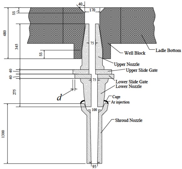
The dimension of the slide-nozzle system and the shroud system
After a casting with 10 heats, where ladle nozzles clogging happened, the samples of the nozzle system and the solid steel in the upper nozzle were taken, as shown in Figure 2. From it, we can see that the edge of a cross section of the solid steel in the upper nozzle was a smooth circle, which indicated there was no obvious clogging in the upper nozzle. However, we found some apparent loose regions with a lot of inclusions and holes around the slide gate, especially at the corner between the upper slide gate and the lower one and close to the wall of the slide gate.
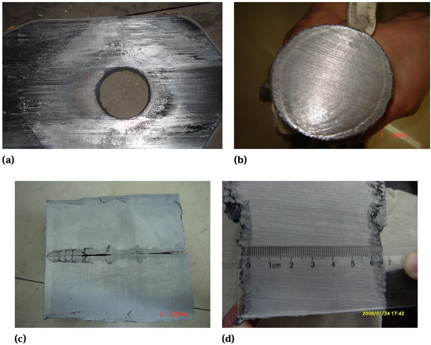
The samples after casting: (a) the used slide gate, (b) a cross section of the solid steel in the upper nozzle, (c) longitudinal sections of the solid steel, (d) a part of Figure 2(c) around the slide gate.
The remaining solid steel in the nozzles was cut into small pieces, and the sampling method is shown in Figure 3 The types, the shapes, the sizes and the distribution of inclusions in the steel samples, which might lead to the ladle nozzle clogging were analyzed by using SEM and EDS.
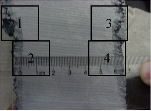
The sampling method (the samples cut from the balck boxs)
3 Theoretical calculation of flow rate during casting
A theoretical flow rate of the liquid steel can be calculated by Equation (1), if suppose the slide gate is fully open [16]:
Where Qm is a flow rate, kg/s. D is the diameter of a nozzle, 0.075 m for the casting. ρl is the density of liquid steel, 7000 kg/m3 for this case. α is a constant, 1 for the turbulent flow studied. g is the acceleration of gravity. h is the height of the liquid level of rest steel from the bottom of a ladle, m. l is a friction loss factor, 0.5 for the case.
A flow rate through the nozzle (Qmc) can be expressed by Equation (2).
where w and t are respectively the width and the thickness of a slab, 1.3 m and 0.23 m for the study. ρs is the density of solid steel, 7797 kg/m3 for the case. sc is a casting speed for two strands, 1.1m/min for the target of this case. Then, based on Equation (2), the Qmc should be 85.48 kg/s, i.e. 5.13 t/min for reaching the target casting speed in the case of the two strands of the CC.
As shown in Figure 4 based on Equation (1) and Equation (2), associated with a decrease of the height of a liquid level, the flow rate deceases. And if a height deceases from 4m to 1.5m, there would be a about 50 percent reduction
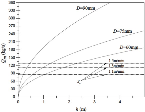
The relationship between Qm/Sc and h during casting
in the flow rate. We can also see that the bigger diameter of a nozzle means a higher flow rate and casting speed. If a nozzle diameter is 90 mm, even though a height is obviously below 0.5 m, the casting speed can reach the target of 1.1m/min. And if a nozzle diameter is 60 mm, even though a height is 1m (two times of the height above), the casting speed will not reach the target (only 0.98 m/min, i.e. 84.14 kg/s). It is indicates that the bigger diameter of a nozzle could effectively generate an enough flow rate for CC.
The theoretical flow rate controlled by an percentage of a slide gate opened, Qmc in kg/s, can be calculated by the following Equation:
where pct is the percentage of a slide gate opened, which can be calculated by Equation (4)
where a is the area of a slide gate opened, m2. d is a distance that a lower slide gate moves, m, also as shown in Figure 1. Based on Equation (4), as shown in Figure 5, we could easily see that with the movement of a slide gate, the slide gate would open bigger and bigger. And a smaller diameter of a nozzle must move more to open the same degree of a bigger one.
The relationship between pct and d during casting
Based on Equation (1), Equation (2) and Equation (3), we could get:
Plug the values of the variables for this study, as shown above, into Equation (5), and it can be reduced to this:
Based on Equation (6), the relationship among pct, Sv, D and h could be shown in Figure 6. If the diameter of a nozzle is 95 mm and the liquid level of rest steel is 4m (at the beginning of a casting), a slide gate opened of 22.54% can lead to the target casting speed of 1.1 m/min. As the liquid level of rest steel decreases to 1m, the slide gate must move to open to 45.09% (two times of the beginning) for reaching the target casting speed. If the nozzle is clogged to a smaller diameter such as 60 mmand the liquid level of rest steel is 1m, almost a fully opened slide gate can meet the demand of the casting speed of 1.1 m/ min. However, as the liquid level of rest steel decreases to 0.5 m, even the slide gate of 100% can not generate the target speed. And at the same time, in order to keep a steady liquid steel level in the tundish, the casting speed has to decrease. From Figure 6, for a fixed slide gate diameter, we could also figure out the appropriate pct that can maintain different casting speeds. Such as 75 mm in this case of a casting speed of 1.1 m/min or 1.5 m/min, the pct at least is supposed to be 32.46% or 44.27% maintaining sufficient liquid steel in the tundish. It can be indicated that if the actual value of pct is higher than the theoretical one of pct, then clogging in the ladle nozzle have been happening.
The Relationship among pct, Sv, D and h
4 Inclusions analysis
As shown in Figure 7, most of inclusions were the ones containing Al2O3, and distributed alone or like a chain. We also observed a small number of pure Al2O3 inclusions and CaO inclusions. The shapes of the composite inclusions were irregular, and their sizes were big, even as large as a few centimeters. We believe that those inclusions were generated from deoxidation and adding the Al content (for meeting performance requirements of the silicon steel) by using Al-alloy, and from the reaction between Al2O3 and slag/furnace lining(Al2O3-MgO-C bricks or MgO-C bricks shown above). We also notice that there were some inclusions with a high contents of FeO, even as high as 50%. It is could be explained that: 1 There was severe air absorbed consuming local [Al], and then the O2 from the air reacted with liquid Fe to form [FeO] (2Fe(l)+O2 =2(FeO)), during the casting. ② EDS might detect the Fe matrix through a thin inclusion. Ahigher content of Fe means a higher likelihood of the second reason happening, and a higher content of oxygen in the inclusions occur due to the first reason. For reducing the error caused by the second reason, we ignored the FeO content of the inclusions, and then the inclusions mainly contained >60% Al2O3, 20~30% MgO+CaO and other components.
Inclusions in steel around the slide gate
Only calculating Al2O3, CaO and MgO, the content and the state (liquid or solid) of each of the inclusions are shown in Figure 8. It could be indicated that almost all the inclusions (96%, 65 of 68)were solid at the casting temperature (1530∘C). The melting points of other three liquid inclusions at the casting temperature were between 1300∘C and 1530∘C, with CaO of 60%~70% in this three-phases diagram. Most of those inclusions with a low melting point would flow away with liquid steel, and not be the reason causing the nozzle clogging.
![Figure 8 The inclusions in the steel in the Al2O3-CaO-MgO diagram with the isograms of the melting points [17]](/document/doi/10.1515/htmp-2019-0038/asset/graphic/j_htmp-2019-0038_fig_008.jpg)
The inclusions in the steel in the Al2O3-CaO-MgO diagram with the isograms of the melting points [17]
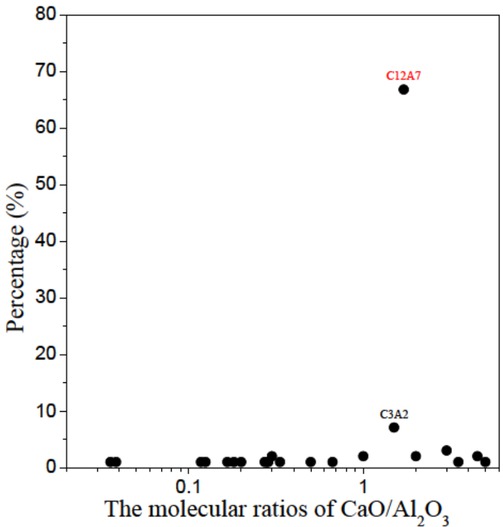
The molecular ratios of the CaO/Al2O3 are shown in Figure 9. An inclusion based on CaO-Al2O3 would become liquid during a casting of steel with its molecular ratio being 1.7 or 3 [18]. However, from the figure, it could be seen that most of the inclusions are not 12CaO·7Al2O3 (or C12A7 for short, whose melting point is the lowest in the slag) or 3CaO·Al2O3 (or C3A for short). And .Therefore, we could use Ca-treatment to transform these inclusions with the high melting-points into those with the lowest melting point of 12CaO·7Al2O3. And improve the nozzle clogging and the final product quality of the silicon steel.
The percentages of the composite inclusions with the different molecular ratios of CaO-Al2O3
5 Ca-treatment for preventing silicon steel from nozzle clogging
5.1 Thermodynamic calculation of Ca-treatment
Ca-treatment is a method that could modify inclusions in steel by adding Si-Ca wires or pure Ca wires and form low melting point inclusions of C12A7 or C3A to prevent nozzle clogging, at a refining unit. In this study, we only dealt with C12A7 (because of the lowest melting point) by using Ca-treatment. C12A7 formed by the reaction of Ca plus Al2O3 can be shown in Equation (7) [19]:
When the reaction is at equilibrium, the relationship between [Al] and [Ca] would be w[Ca]=1.26×10⁻²w[Al]2/3, and the relationship between [Al] and [O] would be w[O]=1.74×10⁻⁵w[Al]−2/3, according to the thermodynamic data and the stoichiometric coefficients [20, 21]. It is indicated that once w[Al] is measured before Ca-treatment, corresponding w[Ca] for forming C12A7 can be determined. And too much or too little Ca would generate other high melting point inclusions, and even sufficient Ca may react with [S] in liquid steel.
Suppose that all oxides reacted with [Ca] is Al2O3, and then the rate of Ca in liquid steel, for the reaction of Equation (7) (CaRe in ppm) can be calculated the following Equation:
Where ArCa and MO are respectively the atomic mass of Ca and O. OT is total oxygen, which includes oxygen in oxides and dissolved oxygen, in steel, ppm. [O] is dissolved oxygen, ppm. And then total Ca in steel (in ppm) can be divided into two parts we refer to as CaRe and Ca at equilibrium (in ppm). Therefore, Si-Ca wires used for Ca-treatment per heat (MSi−Ca in kg) can be calculated by the following Equation:
Where Ms is the capacity of a ladle, 2.1×10⁵ kg for the current study. a is the mass fraction of Ca in a Si-Ca wire, 30% for the current study. y is the yield of the Ca of a Si-Ca wire in steel, 28% for the current study. Furthermore, based on Equation (9), the total length of Si-Ca wires for Ca-treatment per heat (LSi−Ca) can be calculated by:
Where DSi−Ca is the diameter of a Si-Ca wire, 0.013m for the current study. ρSi is the density of Si, 2330 kg/m3. ρCa is the density of Ca, 1550 kg/m3.
As shown in Figure 10 and Figure 11, we could easily get the amount of Si-Ca wires for Ca-treatment of a 210t ladle, with different dissolved Al and total O. From Figure 10, it can be indicated that under a OT, the more dissolved Al is in liquid silicon steel at the end of RH process, the more Si-Ca wires would be needed for Ca-treatment. Figure 11 shows that under a dissolved Al, associated with a increase of total O, Si-Ca wires required raise. For example, in two practical cases, when the dissolved Al is 0.3% and the total O is 30 ppm, and then Si-Ca wires of 867 mwould be required for the Ca-treatment of the heat. However, with the same dissolved Al and the total O of 10 ppm, we just need 678 m. Furthermore, it is necessary to add more Si-Ca wires into liquid silicon steel for Ca-treatment than other steel, because of its higher [Al].
![Figure 10 The relationship between LSi−Ca and w[Al] in liquid silicon steel](/document/doi/10.1515/htmp-2019-0038/asset/graphic/j_htmp-2019-0038_fig_010.jpg)
The relationship between LSi−Ca and w[Al] in liquid silicon steel
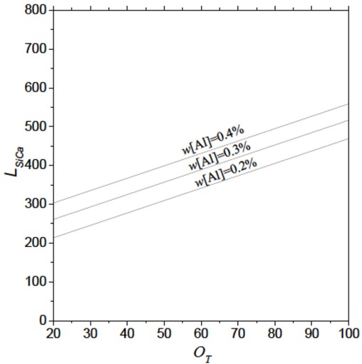
The relationship between LSi−Ca and total oxygen in liquid silicon steel
5.2 Verification tests in steel plant
In order to verify the theoretical analysis mentioned above and prevent a nozzle from clogging during a CC process of the silicon steel, a number of tests were done. These tests were divided into two groups:
The quantity of Si-Ca wires added into the liquid silicon steel for a heat was on the basis of the theoretical analysis. And 15 castings with Ca-treatmentwere tested in a month. The sampling method of the inclusion analysis was the same as what is shown in Figure 3, and three samples were drawn. Through the Ca-treatment, most of inclusions were transformed into C12A7 and there was a small number of C3A2, as shown in Figure 12 And nozzle clogging did not happen in the 15 castings, whose effects were obvious in contrast to the nozzle clogging rate of 1.5% without Ca-treatment.
Al was adjusted to ~0.25% or ~0.35% with basically the same [O] (15~20ppm), and the quantity of Si-Ca wires for a heat was added by the calculation of [Al] of 0.25%. Ca-treatment with the two [Al] were respectively tested 15 castings in two months. The results of the inclusion analysis showed that in the case of [Al]=0.25%, the percentage of C12A7 in the steel was 68.5%, which is more than 53.5% of [Al]=0.35%. It is indicated that Ca-treatment with more [Al] needs more Si-Ca wires.
The percentages of composite inclusions with different CaO: Al2O3 applying Ca-treatment
In conclusion, the results of the two groups of tests fit the theoretical analysis, and Ca-treatment can solve nozzle clogging during a CC process of the silicon steel.
Moreover, the core loss and the magnetic induction of the silicon steel slightly lowered by using Ca-treatment as shown in Table 3.More [Si] might be a reason leading to the little difference, and we will do further research to study the relationship between Ca-treatment and the magnetic properties.
The magnetic properties of the silicon steel with or without Ca-treatment
| Process | Magnetic properties (on average) | |
|---|---|---|
| Core loss, W/Kg | Magnetic induction, T | |
| With | 5.391 | 1.749 |
| Ca-treatment Without | 5.406 | 1.758 |
| Ca-treatment | ||
6 Conclusions
This paper studied the causes of nozzle clogging during a CC process of the silicon steel, and theoretical analyses were done. Furthermore, we figured out a way to solve this problem. We concluded that:
The bigger diameter of a nozzle or less nozzle clogging could effectively generate an enough flow rate for a CC process and maintain the target casting speed. We can predict if nozzle clogging is happening by comparing the actual value and the theoretical one of the percentage of a slide gate opened
The main inclusions which caused the nozzle clogging during a CC process of the silicon steel were Al2O3 and its composite inclusions.
Ca-treatment can be a method that transform inclusions into C12A7 by adding Si-Ca wires and prevent nozzle clogging of the silicon steel theoretically. And the amount of Si-Ca wires for Ca-treatment of the silicon steel, with different dissolved Al and total O can be calculated.
The results of the verification tests fit the theoretical analysis, and Ca-treatment can prevent the nozzles from clogging during a CC process of the silicon steel.
Acknowledgement
This work has been financially supported by “the Fundamental Research Funds for the Central Universities” (Grant No. FRF-TP-16-038A1).
References
[1] S. Basu, C. S. Kumar, and N. U. Girase, ISIJ Int., 44(2007) 1653-1660.10.2355/isijinternational.44.1653Search in Google Scholar
[2] N. U. Girase, S. Basu and S. K. Choudhary, Ironmaking & Steelmaking, 34 (2013) 506-512.10.1179/174328107X168075Search in Google Scholar
[3] H. Liu, Metall. Info. Rev., 47 (2002) 21-22.10.1109/MPER.2002.999660Search in Google Scholar
[4] L. Zhang, Y. Wang, and X. Zuo, Metall. Mater. Trans. B, 39 (2008) 534-550.10.1007/s11663-008-9154-6Search in Google Scholar
[5] H. Cui, Y. P. Bao, M. Wang, and W. S. Wu, Int. J. Miner., Metall. Mater., 17 (2010) 154-158.10.1007/s12613-010-0206-ySearch in Google Scholar
[6] M. Lind and L. Holappa, Metall. Mater. Trans. B, 41 (2010) 359-366.10.1007/s11663-009-9337-9Search in Google Scholar
[7] Z. J. Han, L. Liu, M. Lind, and L. Holappa, Acta Metall. Sin. (Engl. Lett.), 19 (2006) 1-8.10.1016/S1006-7191(06)60017-3Search in Google Scholar
[8] C. B. Shi, X. C. Chen, H. J. Guo, Z. J. Zhu, and H. Ren, Steel Res. Int., 83 (2012) 472-486.10.1002/srin.201100200Search in Google Scholar
[9] F. Chen, X. Huang, Y. Wang, Y. Zhang and Z. Q. Hu, Mater. Lett., 34 (1998) 372-376.10.1016/S0167-577X(97)00197-3Search in Google Scholar
[10] L. Holappa, M. Hämäläinen, M. Liukkonen, and M. Lind, Ironmaking & Steelmaking, 30 (2003) 111-115.10.1179/030192303225001748Search in Google Scholar
[11] X. Zhou, X. Y. Yin, F. Fang, and J. Q. Jiang, Adv. Mater. Res., 217-218 (2011) 457-462.10.4028/www.scientific.net/AMR.217-218.457Search in Google Scholar
[12] A. Chojecki, I. Telejko, and P. Kozelsky, Theor. Appl. Fract. Mech., 31(1999) 41-46.10.1016/S0167-8442(98)00065-2Search in Google Scholar
[13] Z. L. Jin, J. B. Qi, Q. Han and Y. F. Wang, Met. Funct. Mater., 13 (2006) 1-3.Search in Google Scholar
[14] Y. H. Sha, F. Zhang, S.C. Zhou, W. Pei, and L. Zuo, J. Magn. Magn. Mater., 320 (2008) 393-396.10.1016/j.jmmm.2007.06.026Search in Google Scholar
[15] Z. G. Zhang, Y. D. Liu, and W. Fu, Trans. Mater. Heat Treat., 31 (2010) 69-72.Search in Google Scholar
[16] G.H. Geiger and D.R. Poirier, Transport Phenomena in Metallurgy, Addison Wesley, New Jersey, (1973).Search in Google Scholar
[17] A. H. D. Aza, P. Pena, and S. D. Aza, J. Am. Ceram. Soc., 82 (1999) 2193-2203.10.1111/j.1151-2916.1999.tb02062.xSearch in Google Scholar
[18] L. Holappa, M. Hämäläinen, M. Liukkonen, and M. Lind, Ironmaking & Steelmaking, 30 (2003) 111-115.10.1179/030192303225001748Search in Google Scholar
[19] Z. Kalicka, Arch. Metall., 47 (2002) 375-383.10.1016/S0738-3991(02)00143-XSearch in Google Scholar
[20] S. Wu, Y. Wang, L. Zhang and J. Zhang, Thermodynamics and kinetics of SEN clogging during continuous casting of A1-killed steels, AISTech (May 5-8, 2008), Pennsylvania, Pittsburgh, (2009), pp. 543-558.Search in Google Scholar
[21] K. Chattopadhyay and S. M. S. Kumar, Thermodynamic Evaluation of Inclusion Formation and Nozzle Clogging During Slab Casting, AISTech (May 5-8, 2014), Indianapolis, Indiana, (2015), pp. 1815-1821.Search in Google Scholar
© 2019 W. Kong et al., published by De Gruyter
This work is licensed under the Creative Commons Attribution 4.0 Public License.
Articles in the same Issue
- Frontmatter
- Review Article
- Research on the Influence of Furnace Structure on Copper Cooling Stave Life
- Influence of High Temperature Oxidation on Hydrogen Absorption and Degradation of Zircaloy-2 and Zr 700 Alloys
- Correlation between Travel Speed, Microstructure, Mechanical Properties and Wear Characteristics of Ni-Based Hardfaced Deposits over 316LN Austenitic Stainless Steel
- Factors Influencing Gas Generation Behaviours of Lump Coal Used in COREX Gasifier
- Experiment Research on Pulverized Coal Combustion in the Tuyere of Oxygen Blast Furnace
- Phosphate Capacities of CaO–FeO–SiO2–Al2O3/Na2O/TiO2 Slags
- Microstructure and Interface Bonding Strength of WC-10Ni/NiCrBSi Composite Coating by Vacuum Brazing
- Refill Friction Stir Spot Welding of Dissimilar 6061/7075 Aluminum Alloy
- Solvothermal Synthesis and Magnetic Properties of Monodisperse Ni0.5Zn0.5Fe2O4 Hollow Nanospheres
- On the Capability of Logarithmic-Power Model for Prediction of Hot Deformation Behavior of Alloy 800H at High Strain Rates
- 3D Heat Conductivity Model of Mold Based on Node Temperature Inheritance
- 3D Microstructure and Micromechanical Properties of Minerals in Vanadium-Titanium Sinter
- Effect of Martensite Structure and Carbide Precipitates on Mechanical Properties of Cr-Mo Alloy Steel with Different Cooling Rate
- The Interaction between Erosion Particle and Gas Stream in High Temperature Gas Burner Rig for Thermal Barrier Coatings
- Permittivity Study of a CuCl Residue at 13–450 °C and Elucidation of the Microwave Intensification Mechanism for Its Dechlorination
- Study on Carbothermal Reduction of Titania in Molten Iron
- The Sequence of the Phase Growth during Diffusion in Ti-Based Systems
- Growth Kinetics of CoB–Co2B Layers Using the Powder-Pack Boriding Process Assisted by a Direct Current Field
- High-Temperature Flow Behaviour and Constitutive Equations for a TC17 Titanium Alloy
- Research on Three-Roll Screw Rolling Process for Ti6Al4V Titanium Alloy Bar
- Continuous Cooling Transformation of Undeformed and Deformed High Strength Crack-Arrest Steel Plates for Large Container Ships
- Formation Mechanism and Influence Factors of the Sticker between Solidified Shell and Mold in Continuous Casting of Steel
- Casting Defects in Transition Layer of Cu/Al Composite Castings Prepared Using Pouring Aluminum Method and Their Formation Mechanism
- Effect of Current on Segregation and Inclusions Characteristics of Dual Alloy Ingot Processed by Electroslag Remelting
- Investigation of Growth Kinetics of Fe2B Layers on AISI 1518 Steel by the Integral Method
- Microstructural Evolution and Phase Transformation on the X-Y Surface of Inconel 718 Ni-Based Alloys Fabricated by Selective Laser Melting under Different Heat Treatment
- Characterization of Mn-Doped Co3O4 Thin Films Prepared by Sol Gel-Based Dip-Coating Process
- Deposition Characteristics of Multitrack Overlayby Plasma Transferred Arc Welding on SS316Lwith Co-Cr Based Alloy – Influence ofProcess Parameters
- Elastic Moduli and Elastic Constants of Alloy AuCuSi With FCC Structure Under Pressure
- Effect of Cl on Softening and Melting Behaviors of BF Burden
- Effect of MgO Injection on Smelting in a Blast Furnace
- Structural Characteristics and Hydration Kinetics of Oxidized Steel Slag in a CaO-FeO-SiO2-MgO System
- Optimization of Microwave-Assisted Oxidation Roasting of Oxide–Sulphide Zinc Ore with Addition of Manganese Dioxide Using Response Surface Methodology
- Hydraulic Study of Bubble Migration in Liquid Titanium Alloy Melt during Vertical Centrifugal Casting Process
- Investigation on Double Wire Metal Inert Gas Welding of A7N01-T4 Aluminum Alloy in High-Speed Welding
- Oxidation Behaviour of Welded ASTM-SA210 GrA1 Boiler Tube Steels under Cyclic Conditions at 900°C in Air
- Study on the Evolution of Damage Degradation at Different Temperatures and Strain Rates for Ti-6Al-4V Alloy
- Pack-Boriding of Pure Iron with Powder Mixtures Containing ZrB2
- Evolution of Interfacial Features of MnO-SiO2 Type Inclusions/Steel Matrix during Isothermal Heating at Low Temperatures
- Effect of MgO/Al2O3 Ratio on Viscosity of Blast Furnace Primary Slag
- The Microstructure and Property of the Heat Affected zone in C-Mn Steel Treated by Rare Earth
- Microwave-Assisted Molten-Salt Facile Synthesis of Chromium Carbide (Cr3C2) Coatings on the Diamond Particles
- Effects of B on the Hot Ductility of Fe-36Ni Invar Alloy
- Impurity Distribution after Solidification of Hypereutectic Al-Si Melts and Eutectic Al-Si Melt
- Induced Electro-Deposition of High Melting-Point Phases on MgO–C Refractory in CaO–Al2O3–SiO2 – (MgO) Slag at 1773 K
- Microstructure and Mechanical Properties of 14Cr-ODS Steels with Zr Addition
- A Review of Boron-Rich Silicon Borides Basedon Thermodynamic Stability and Transport Properties of High-Temperature Thermoelectric Materials
- Siliceous Manganese Ore from Eastern India:A Potential Resource for Ferrosilicon-Manganese Production
- A Strain-Compensated Constitutive Model for Describing the Hot Compressive Deformation Behaviors of an Aged Inconel 718 Superalloy
- Surface Alloys of 0.45 C Carbon Steel Produced by High Current Pulsed Electron Beam
- Deformation Behavior and Processing Map during Isothermal Hot Compression of 49MnVS3 Non-Quenched and Tempered Steel
- A Constitutive Equation for Predicting Elevated Temperature Flow Behavior of BFe10-1-2 Cupronickel Alloy through Double Multiple Nonlinear Regression
- Oxidation Behavior of Ferritic Steel T22 Exposed to Supercritical Water
- A Multi Scale Strategy for Simulation of Microstructural Evolutions in Friction Stir Welding of Duplex Titanium Alloy
- Partition Behavior of Alloying Elements in Nickel-Based Alloys and Their Activity Interaction Parameters and Infinite Dilution Activity Coefficients
- Influence of Heating on Tensile Physical-Mechanical Properties of Granite
- Comparison of Al-Zn-Mg Alloy P-MIG Welded Joints Filled with Different Wires
- Microstructure and Mechanical Properties of Thick Plate Friction Stir Welds for 6082-T6 Aluminum Alloy
- Research Article
- Kinetics of oxide scale growth on a (Ti, Mo)5Si3 based oxidation resistant Mo-Ti-Si alloy at 900-1300∘C
- Calorimetric study on Bi-Cu-Sn alloys
- Mineralogical Phase of Slag and Its Effect on Dephosphorization during Converter Steelmaking Using Slag-Remaining Technology
- Controllability of joint integrity and mechanical properties of friction stir welded 6061-T6 aluminum and AZ31B magnesium alloys based on stationary shoulder
- Cellular Automaton Modeling of Phase Transformation of U-Nb Alloys during Solidification and Consequent Cooling Process
- The effect of MgTiO3Adding on Inclusion Characteristics
- Cutting performance of a functionally graded cemented carbide tool prepared by microwave heating and nitriding sintering
- Creep behaviour and life assessment of a cast nickel – base superalloy MAR – M247
- Failure mechanism and acoustic emission signal characteristics of coatings under the condition of impact indentation
- Reducing Surface Cracks and Improving Cleanliness of H-Beam Blanks in Continuous Casting — Improving continuous casting of H-beam blanks
- Rhodium influence on the microstructure and oxidation behaviour of aluminide coatings deposited on pure nickel and nickel based superalloy
- The effect of Nb content on precipitates, microstructure and texture of grain oriented silicon steel
- Effect of Arc Power on the Wear and High-temperature Oxidation Resistances of Plasma-Sprayed Fe-based Amorphous Coatings
- Short Communication
- Novel Combined Feeding Approach to Produce Quality Al6061 Composites for Heat Sinks
- Research Article
- Micromorphology change and microstructure of Cu-P based amorphous filler during heating process
- Controlling residual stress and distortion of friction stir welding joint by external stationary shoulder
- Research on the ingot shrinkage in the electroslag remelting withdrawal process for 9Cr3Mo roller
- Production of Mo2NiB2 Based Hard Alloys by Self-Propagating High-Temperature Synthesis
- The Morphology Analysis of Plasma-Sprayed Cast Iron Splats at Different Substrate Temperatures via Fractal Dimension and Circularity Methods
- A Comparative Study on Johnson–Cook, Modified Johnson–Cook, Modified Zerilli–Armstrong and Arrhenius-Type Constitutive Models to Predict Hot Deformation Behavior of TA2
- Dynamic absorption efficiency of paracetamol powder in microwave drying
- Preparation and Properties of Blast Furnace Slag Glass Ceramics Containing Cr2O3
- Influence of unburned pulverized coal on gasification reaction of coke in blast furnace
- Effect of PWHT Conditions on Toughness and Creep Rupture Strength in Modified 9Cr-1Mo Steel Welds
- Role of B2O3 on structure and shear-thinning property in CaO–SiO2–Na2O-based mold fluxes
- Effect of Acid Slag Treatment on the Inclusions in GCr15 Bearing Steel
- Recovery of Iron and Zinc from Blast Furnace Dust Using Iron-Bath Reduction
- Phase Analysis and Microstructural Investigations of Ce2Zr2O7 for High-Temperature Coatings on Ni-Base Superalloy Substrates
- Combustion Characteristics and Kinetics Study of Pulverized Coal and Semi-Coke
- Mechanical and Electrochemical Characterization of Supersolidus Sintered Austenitic Stainless Steel (316 L)
- Synthesis and characterization of Cu doped chromium oxide (Cr2O3) thin films
- Ladle Nozzle Clogging during casting of Silicon-Steel
- Thermodynamics and Industrial Trial on Increasing the Carbon Content at the BOF Endpoint to Produce Ultra-Low Carbon IF Steel by BOF-RH-CSP Process
- Research Article
- Effect of Boundary Conditions on Residual Stresses and Distortion in 316 Stainless Steel Butt Welded Plate
- Numerical Analysis on Effect of Additional Gas Injection on Characteristics around Raceway in Melter Gasifier
- Variation on thermal damage rate of granite specimen with thermal cycle treatment
- Effects of Fluoride and Sulphate Mineralizers on the Properties of Reconstructed Steel Slag
- Effect of Basicity on Precipitation of Spinel Crystals in a CaO-SiO2-MgO-Cr2O3-FeO System
- Review Article
- Exploitation of Mold Flux for the Ti-bearing Welding Wire Steel ER80-G
- Research Article
- Furnace heat prediction and control model and its application to large blast furnace
- Effects of Different Solid Solution Temperatures on Microstructure and Mechanical Properties of the AA7075 Alloy After T6 Heat Treatment
- Study of the Viscosity of a La2O3-SiO2-FeO Slag System
- Tensile Deformation and Work Hardening Behaviour of AISI 431 Martensitic Stainless Steel at Elevated Temperatures
- The Effectiveness of Reinforcement and Processing on Mechanical Properties, Wear Behavior and Damping Response of Aluminum Matrix Composites