Exploitation of Mold Flux for the Ti-bearing Welding Wire Steel ER80-G
-
Zhanlong Piao
 ,
Xingjuan Wang
,
Xingjuan Wang

Abstract
In order to improve the surface defects of strand, the mold flux is exploited for the Ti-bearing welding wire steel ER80-G. The composition of mold flux is designed by analyzing the solidification characteristics of ER80-G and the slag system isothermal section diagram, simulating by the FactSage thermodynamics software. The Ti-bearing welding wire steel ER80-G belongs to the peritectic steel. The melting point range of the newly designed mold flux system is from 1030∘C to 1129∘C, the melting rate range is from 58 s to 64 s, the viscosity range at the temperature of 1300∘C is from 0.33 Pa·s to 0.50 Pa·s, the crystallization temperature range is from 1160∘C to 1293∘C, the crystalline fraction range is from 34% to 85%. The surface defects of strand which transverse depression, longitudinal depression, slag runner and so on were obviously improved when the newly design mold flux F3, F5, F9 were used to the production respectively. Those results suggest that 0.9 basicity with 28.4%-CaO, 31.6%-SiO2,3%-MgO, 10%-Na2O, 10%-CaF2, 6%-Al2O3, 1%-Fe2O3, 10%-Tc and all groups with 1.0 and 1.1 basicity show the best properties for Ti-bearing welding wire steel ER80-G.
1 Introduction
The TiN was from the combination of [Ti] and [N] plays a role in nitrogen fixation for the Ti-bearing welding wire steel ER80-G, which improves the ability of weld metal to resist nitrogen gas holes and reduces spatter 30% to 50%. This steel is widely applied in the welding field, such as automobiles, ships, bridges and other steel structure [1, 2, 3, 4, 5]. But the difficulty of continuous casting is resulted from nozzle blocking and cold steel, and there are a lot of surface defects of strand, such as transverse depression, longitudinal depression, slag runner and slag pit and so on.
The Ti-bearing welding wire steel invented firstly in Japan had less spatter and better deposited property, and then it was extensive popularization [6, 7]. Shagang [9], qinggang [10], tanggang [11] and taigang [12] had produced Ti-bearing welding wire steel, who overcome the problem of nozzle blocking and cold steel through the optimization of the relation of [Al]-[Ti]-[O]-[N] and process parameters. But the researches about the surface defects of Ti-bearing welding wire steel ER80-G are relatively few. The surface quality is closely related to the properties of mold flux, if the viscosity and melting point is high, which will result that the liquid flux layer become thinner and then the sintered layer and powder layer are easier to flow into the gap when the mold oscillated, meanwhile the liquid flux layer flowed unsteadily makes the heat-transfer nonuniformly, which may cause surface defects.
The mold flux for Ti-bearing welding wire steel ER80-G is special because of exciting the steel-slag interface reaction, [Ti] + (SiO2) = (TiO2) + [Si], which is occurred in the mold in continuous casting. It changes the content of mold fluxes, increases the basicity and the melting temperature, reduces the viscosity [13, 14, 15, 16, 17, 18]. So the liquid slag layer is not stable, and then leads to poor lubrication and heat-transfer.
The mold flux plays an important role in the continuous casting, and its structure in the mold is illustrated in Figure 1. The liquid slag layer, sintered layer and powdered slag layer are over the surface of the molten steel, and the liquid slag film, crystalline film and glassy slag film are located between the mold wall and initial shell [19]. The liquid slag film acted as the lubrication can reduce the friction between the mold wall and the shell, the crystalline film can control the horizontal heat transfer of the shell [20, 21, 22, 23, 24, 25, 26].

The schematic figure of mold flux structure
According to the process parameters of Ti-bearing welding wire steel ER80-G, its solidification characteristics and the effect of components on the melting temperature and viscosity of slag system were simulated by Fact-Sage thermodynamics software, and the viscosity obeyed the empirical formula, ŋ1300∘C·Vc=0.5~0.7 [19], for the Ti-bearing welding wire steel ER80-G, which the casting section size was 165 mm×165 mm and the casting speed was 1.7 m/min, and then the composition of mold flux was designed. The relatively physical and chemical properties, melting characteristic, viscosity characteristic and crystallization characteristic were measured by the automatic tester slag melting point and melting speed, the brookfield rotary viscometer and the SHTT/DHTT. And then the component content of mold flux for Ti-bearing welding wire steel ER80-G was decided by analyzing the measured results, which had guidance significance in designing the mold flux.
2 Experimental Methods
The solidification characteristics of Ti-bearing welding wire steel ER80-G was simulated by the scheil solidification of “Equilib” module in FactSage software, the calculation temperature was set at 1530∘C~1430∘C for observing the solidification process at high temperature, the carbon content was set at 0~0.2% for studying the effect of the different carbon content on the solidification mode, and the composition were listed in Table 1.
Composition of the Ti-bearing welding wire steel ER80-G(wt%)
| C | Si | Mn | S | P | Ni | Mo | Cr | Ti |
|---|---|---|---|---|---|---|---|---|
| 0.07~0.09 | 0.40~0.50 | 1.50~1.60 | ≤ 0.015 | ≤ 0.02 | 1.60~1.75 | 0.30~0.45 | 0.35~0.45 | 0.05~0.07 |
The mold flux was exploited based on a commercial benchmark mold flux for the Ti-bearing welding wire steel ER80-G, the specific components were listed in Table 2. The F0 represented the original mold flux was CaO-SiO2- Al2O3 traditional base slag system.
The specific components of original mold flux(wt%)
| Flux | CaO | SiO2 | R | Al2O3 | Fe2O3 | Na2O | CaF2 | MgO | Tc |
|---|---|---|---|---|---|---|---|---|---|
| F0 | 28.9 | 31.8 | 0.9 | 5.6 | 1 | 5 | 4.6 | 0.8 | 16 |
The design direction of mold flux was decided by the solidification characteristic of the Ti-bearing welding wire steel ER80-G. Meanwhile, the “phase diagram” module of FactSage software was used for simulating the ternary phase diagrams to analyze the effect of the component on the melting temperature of mold flux, and the “Equilib” module and “Viscosity” module of FactSage software were used for calculating the viscosity of mold flux at the temperature of 1300∘C, and the Einstein-Roscoe Equation used in viscosity calculation of solid and liquid mixtureswas shown in equation 1. The component content range of mold flux was designed according to the simulated results of FactSage software.
Where the Viscosity(solid+liquidmixture) is the calculated viscosity of mixtures, Viscosity(liquid) is the viscosity of liquid flux, which can be calculated from “Viscosity” module from mold flux component calculated from “Equilib” module; the solid fraction is the volume fraction of solid in mixtures, which can be calculated using “Equilib” module at given flux system composition.
The automatic tester slag melting point and melting speed was used to test the melting characteristic, its accuracy was ±3∘C. A cylinder φ 3 mm×3 mm prepared by grinding the mold flux to 200 mesh was heated in the heating furnace, the height of the sample was observed during the melting process and the melting temperature was determined according to the industry standard (YB/T 186-2001) which was from China. The temperature at which the height of the sample become 3/4 of the original height is used as the softening temperature, the corresponding temperatures of 1/2 and 1/4 are respectively the melting point and flowing temperature of mold flux. Firstly, the K2SO4, the melting temperature is 1067∘C, was used as the standard sample to judge the accuracy of the equipment. Secondly, the mold flux sample was tested three times with the difference between the highest test value and the lowest test value was less than 20∘C, and then the corresponding temperature was obtained by calculating the average value of three test. If not, it will test again. The melting rate was expressed by the melting time of the sample tested at 1350∘C, the sample was also tested three times and then calculated the average value of it. The schematic automatic tester slag melting point and melting speed was shown in Figure 2.

The schematic automatic tester slag melting point and melting speed
The viscosity of mold flux was tested by the Brookfield Rotary Viscometer. 300g carbon-free mold flux was put into the graphite crucible of φ 56 mm × 80 mm. It was heated in MoSi2 furnace and heated to 1400∘C for 10 min, which made the composition of mold powder uniformly. The viscosity was measured when the temperature down to 1300∘C. The schematic of Brookfield Rotary Viscometer was shown in Figure 3.
The schematic of brookfield rotary viscometer
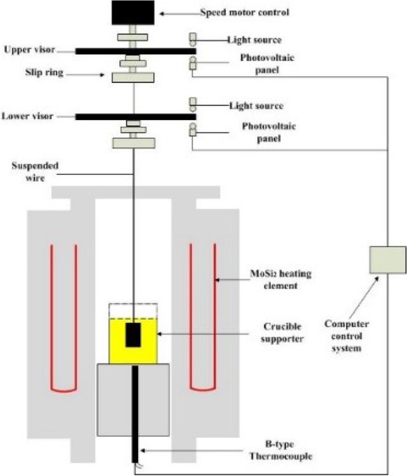
The crystallization temperature and the crystalline fraction were measured by the SHTT/DHTT. Firstly, the sample was decarburized completely in the muffler furnace at 700∘C. Secondly, the sample which must be mixed well was grinded to 200 mesh. Thirdly, the sample which was prepared into a paste with the anhydrous ethanol was mounted on a B type thermocouple with the specific temperature control system. The sample was heated to 1500∘C at a rate of 10∘C/s and kept for 5 minutes to eliminate bubbles and homogenize chemical composition, and it was tested with the cooling rate was 50∘C/s. The K2SO4, the melting temperature is 1067∘C, was used as the standard sample to judge the accuracy of the equipment before measuring the sample. The crystallization temperature of mold flux was achieved by calculating the average value of three times testing results whose difference was less than ±10∘C, if not, it need to do it again. The crystalline fraction was calculated by the software. The schematic of SHTT/DHTT was shown in Figure 4.

The schematic of SHTT/DHTT
3 Results and Discussion
3.1 The solidification characteristics
Figure 5 showed the solidification characteristics of the welding wire steel containing titanium ER80-G.

The solidification process of ER80-G on high temperature
The liquidus temperature of the welding wire steel containing titanium ER80-G was about 1513∘C. Its solidification mode was L→ L+δ→ L+γ+δ→ L+γ→ γ. The peritectic reaction, L+δ→ γ, appeared among 1490∘C~1485∘C, which was belong to peritectic steel. The compactness degree of the austenite which is a face-centered cubic structure is higher than the ferrite δ which is a body-centered cubic structure [27, 28, 29]. The volume of the strand shrunk sharply when the peritectic reaction occurred. If the mold flux did not flow evenly, the heat-transfer of the strand shell will be uneven, and the surface quality problem will be easily caused.
Heat-transfer Control should be considered in designing newly mold flux of Ti-bearing welding wire steel ER80-G. The horizontal heat-transfer of the initial strand shell at the meniscus can be controlled by adjusting the crystallization temperature and crystalline fraction of the mold flux [30].Meanwhile, the viscosity, melting point and melting rate of the mold flux should be considered for ensuring the reasonable flow of the liquid flux layer and the good lubricating effect.
3.2 The isothermal section phase diagram
Figure 6 showed the CaO-SiO2-Al2O3 ternary phase diagram was calculated by the FactSage simulation software. The temperature was set at 1100∘C~1600∘C and the step length was 20∘C in order to fit the actual production conditions.

CaO-SiO2-Al2O3 ternary phase diagram
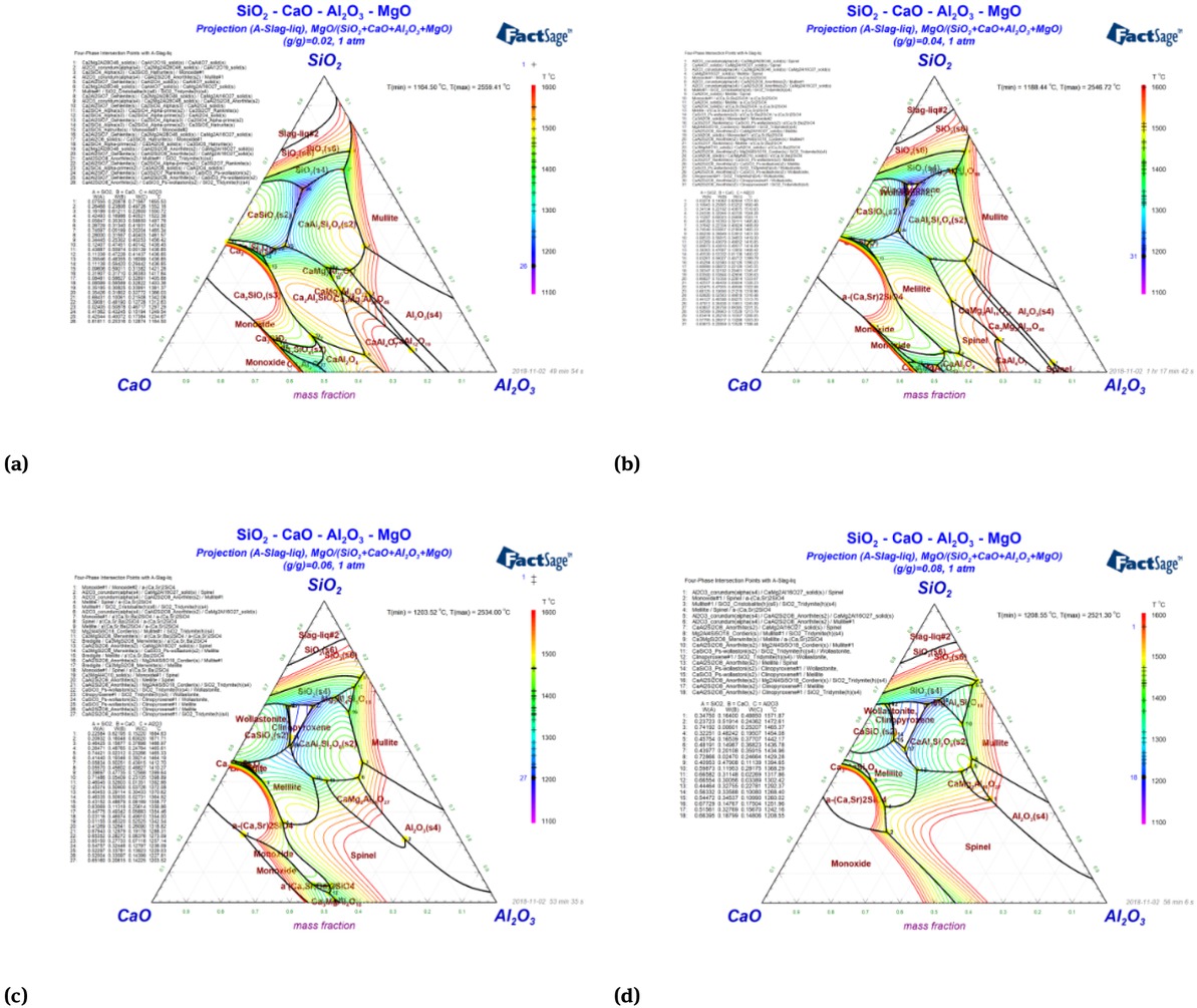
The precipitation temperature range of mineral phase was from 1184∘C to 1726∘C the melting temperature of the region surrounded by blue curve was lower, about 1184∘C~1298∘C. There was a lower melting point region nearby number 28 corresponding to the lower basicity of the mold flux which was disadvantage for the control heat-transfer of strand shell. The low melting point region also appeared near the number 26 and 27 corresponding to the basicity range of the mold flux was among 0.9~1.1, which was shown by the isobaric curve 1 and 2. So the binary basicity of CaO-SiO2-Al2O3 slag system was designed at 0.9~1.1.
The effects of different contents of CaF2, Na2O and MgO on the melting temperature and viscosity of CaO-SiO2-Al2O3 ternary slag system were calculated by the FactSage software, and the optimum content range of them was studied out.
Figure 7 showed the isothermal section of the CaO-SiO2-Al2O3 ternary slag system with the content of CaF2 was 4%, 6%, 8% and 10%.

The isothermal section of the CaO-SiO2-Al2O3 ternary slag system with the content of CaF2 is 4%, 6%, 8% and 10%
The temperature of blue isotherm curve was about 1250∘C, which was the low melting point region, and the temperature of isotherm curve increased orderly from inside to outside. The low melting point region increased gradually with the increase of CaF2, which suggested that the CaF2 could significantly reduce the melting temperature of mold flux. Long et al. [31] considered that CaF2 which was less than 12% could obviously decrease the melting temperature of high basicity mold flux. Wang et al. [32] found that B2O3 and CaF2 could reduce the melting temperature, so did the viscosity. So the CaF2 content range was designed at 4%~10%.
Figure 8 showed the isothermal section of the CaO-SiO2-Al2O3 ternary slag system with the content of MgO was 2%, 4%, 6% and 8%.
The isothermal section of the CaO-SiO2-Al2O3 ternary slag system with the content of MgO is 2%, 4%, 6% and 8%
With the content of MgO increased, the low melting point region moves to low basicity, the melting temperature increases and the crystallization regions of wollastonite and clinopyroxene gradually expanses. When the basicity was 0.9~1.1 and MgO content was 2%, there was a low melting point region. Wang et al. [33] found that increasing 1%MgO will increase the melting temperature by about 20∘C when the MgO content was among 2%~8%. So the MgO content was designed at 1%~3%.
Figure 9 showed the isothermal section of the CaO-SiO2-Al2O3 ternary slag system with the content of Na2O was 5%, 7%, 9% and 11%.

The isothermal section of the CaO-SiO2-Al2O3 ternary slag system with the content of Na2O is 5%, 7%, 9% and 11%
With the Na2O content increased, the low melting point region enlarges gradually and its temperature decreases from 1130∘C to 994∘C. Na2O could reduce obviously the melting temperature, so the composition of CaO-SiO2-Al2O3 slag system could be adjusted in a wide range. The researches confirmed the result [31, 34, 35]. So the Na2O content was designed at 5%~11%.
The viscosity of mold flux with different contents of MgO, Na2O, CaF2 were computed by the “Equilib” model and “Viscosity” model of FactSage software. Figure 10 showed variation curve of component content and viscosity which was drew by Origin software.

The variation curve of component content and viscosity
With the content of MgO, Na2O, CaF2 increased, the mold flux viscosity is reduced. However, the degree of viscosity reduction was different among the three components, and the order of their ability to reduce viscosity was CaF2>Na2>MgO.
In summary, the base slag system of mold flux was proposed as CaO-SiO2-Al2O3 ternary slag system, and the basicity was 0.9~1.1. The content of MgO was 1%~3%, the content of Na2O was 6%~10%, the content of CaF2 was 8%~10%, the content of Al2O3 was 6% and the content of Fe2O3 was 1%. The carbon material whose content was 10%was made up graphite and carbon black, and the ratio of them was 2:1. F1~F9 was the newly design of nine groups of CaO-SiO2-Al2O3 slag system. The specific components were listed in Table 3.
The specific components of mold fluxes (wt%)
| level | element | ||||||||
|---|---|---|---|---|---|---|---|---|---|
| CaO | SiO2 | R | Al2O3 | Fe2O3 | Na2O | CaF2 | MgO | Tc | |
| F1 | 32.2 | 35.8 | 0.9 | 6 | 1 | 6 | 8 | 1 | 10 |
| F2 | 30.3 | 33.7 | 0.9 | 6 | 1 | 8 | 9 | 2 | 10 |
| F3 | 28.4 | 31.6 | 0.9 | 6 | 1 | 10 | 10 | 3 | 10 |
| F4 | 32.5 | 32.5 | 1.0 | 6 | 1 | 6 | 10 | 2 | 10 |
| F5 | 32 | 32 | 1.0 | 6 | 1 | 8 | 8 | 3 | 10 |
| F6 | 31.5 | 31.5 | 1.0 | 6 | 1 | 10 | 9 | 1 | 10 |
| F7 | 33 | 31 | 1.1 | 6 | 1 | 6 | 9 | 3 | 10 |
| F8 | 33.5 | 30.5 | 1.1 | 6 | 1 | 8 | 10 | 1 | 10 |
| F9 | 33 | 30 | 1.1 | 6 | 1 | 10 | 8 | 2 | 10 |
3.3 The melting characteristic
Figure 11 showed the results of softening temperature, melting point, flowing temperature and melting rate of mold fluxes were from the automatic tester slag melting point and melting speed.

The melting temperature of fluxes 0 through 10
The softening temperature of the original mold flux was 1118∘C, the melting point was 1123∘C, the flowing temperature was 1233∘C and the melting rate was 140s. The softening temperature range of nine groups newly designed mold flux was from 977∘C to 1116∘C, the melting point range was from 1030∘C to 1129∘C, the flowing temperature range was from 1072∘C to 1163∘C, and the melting rate range was from 58 s to 64 s.
With the content of MgO, Na2O and CaF2 increased, the softening temperature, melting point and liquidus temperature [36] of the mold flux show a decreasing trend by comparing the melting temperatures of F0, F1, F2 and F3 groups with basicity of 0.9. The function of MgO, Na2O, CaF2 which could decrease the melting temperature was agreed with the basicity of 1.0 and 1.1.
R1, R2 and R3 represented respectively the basicity of 0.9, 1.0 and 1.1, N1, N2, N3 represented respectively the 6%, 8% and 10% content of Na2O, M1, M2, M3 represented respectively the 1%, 2%, 3% content of MgO, C1, C2 and C3 represented respectively the 8%, 9% and 10% content of CaF2. The melting point sequence was HR3>HR2>HR1, HN1>HN2>HN3, HM1>HM2>HM3, HC1>HC2>HC3 by means of weighted average calculation of melting temperatures of different groups. The results showed that the melting point of mold flux increased with the increase of basicity, while both Na2O, MgO and CaF2 could decrease the melting point.
The average melting rate of F1~F9 was about 60 s, but F0 was 140s. The results showed that the melting rate of mold flux decreased obviously with the carbon content increased.
3.4 The viscosity characteristic
Figure 12 showed the testing results of the viscosity of mold fluxes were from the Brookfield Rotary Viscometer.

The viscosity of fluxes 0 through 10
The viscosity of original mold flux was 0.73 Pa·s at the temperature of 1300∘C. The viscosity of nine groups newly designed mold flux range were from 0.33 Pa·s to 0.50 Pa·s at the temperature of 1300∘C.
The viscosity sequence was ηR1>ηR2>ηR3 by means of weighted average calculation of the viscosity of mold fluxes with different basicity. The result showed that the viscosity of mold flux decreased with the basicity increased. Figure 13 showed the reaction process between CaO and chain-like silico-oxygen tetrahedron, the O2− coming from CaO could replace the bridging oxygen in chain-like silico-oxygen tetrahedron, which was called non-bridging oxygen, and it could make the chain-like structure turn to sample. The number of non-bridging oxygen and the oxygen-silicon ratio increased when the basicity, the content of MgO and Na2O increased, so the viscosity was decreased. There were two distinct models for the role of CaF2 in silicate network structure [37], one was the Bills models, which held that CaF2 was mainly used as diluent and not involved in breaking bridge oxygen. The other was Geist models, which suggested that CaF2 was used as network modifier. Some researches [38, 39, 40, 41, 42, 43] suggested that Si-F bond was formed by replaced the O atom of the Si-O bond.However, Sasaki et al. [44] and Gao et al. [45] found that Si-F bond could not form in the Na2O-NaF-SiO2 slag system. Mills [46] thought that CaF2 was only used as diluent to decreased the viscosity. Persson and Seetharaman [47] suggested that CaF2 was used as network modifier in the acid silicate slag and worked as diluent in the alkaline silicate slag. Regardless of the role of CaF2, it could decrease the viscosity of mold flux.

The reaction process of CaO and chain-like silico-oxygen tetrahedron
The viscosity sequence was ηM1>ηM2>ηM3, ηN1>ηN2>ηN3 and ηC1>ηC2>ηC3 by means of weighted average calculation of the viscosity of different groups. The results showed that MgO, Na2O and CaF2 could reduce the viscosity as same as the FactSage simulated results. In terms of the effective of decreasing viscosity, the CaF2 was better than the Na2O, and the MgO was the last.
3.5 The crystallization characteristic
Figure 14 showed the crystallization temperature and crystalline fraction of ten groups mold flux by the SHTT/DHTT.

The crystallization temperature and crystalline fraction of mold flux
The crystalline fraction sequence was R3>R2>R1 by means of weighted average calculation of the crystalline fraction of different groups mold flux, which illustrated that increasing basicity of mold flux was beneficial to crystalline.
The crystallization temperature of F0 was 1045∘C, and the strand shell temperature located at the outlet of mold was about 1100∘C [30], it meant that there was no liquid slag film which resulted the poor lubrication effect. The effective of heat-transfer control was bad because of its crystalline fraction was 15%. If it was applied to the production of peritectic steel, the surface longitudinal crack was easy to happen. The crystallization temperature range of F1~F9 were over 1100∘C. The crystalline fraction of F1 and F2were 34% and 42%, which were relative low resulting in the unsatisfactory effect of heat-transfer control. The crystalline fraction range of F3~F9 was from 56% to 85%, they not only ensured the lubrication function, but controlled effectively the horizontal heat-transfer of initial strand shell, which was benefit for the surface quality.
4 Application Effect
The production process of the Ti-bearing welding wire steel ER80-G was that: 120 t converter – LF refining – the continuous casting. The size of strand was 165 mm × 165 mm, the casting speed was 1.7 m/min, the mold taper was 0.87%/m, the casting temperature was among 1530∘C~1560∘C. The mold flux F0, F3, F5 and F9 were applied to the production of Ti-bearing welding wire steel ER80-G. Figure 15 showed the original morphology of strand surface using different mold fluxes.

The original morphology of strand surface
There were transverse depression with equal spacing, longitudinal depression of different length, slag pit, slag runner appearing on the strand surface when the mold flux F0 was used in the production of Ti-bearing welding wire steel ER80-G. The poor strand surface quality was closely related to the mold flux F0. The melting rate, 140 s, was slow, the melting point, 1123∘C, was normal, so the liquid slag layer became thinner resulting of it flowing into the gap which located between the mold wall and initial strand shell could not be replenished in time. So the sintered layer was easier to flow into the gap when the mold oscillated, and the powdered slag layer may be also flowed into the gap together, resulting in the increase of friction between the initial strand shell and the mold wall, and then the slag runner and the slag pit were easy to appear. The viscosity, 0.73 Pa·s, was relatively high, resulting in the poor fluidity of the liquid slag layer and the non-homogeneous of liquid slag film, and then the heat-transfer of strand shell was non-uniform, which was easy to cause the surface depression and longitudinal crack for the Ti-bearing welding wire steel ER80-G with peritectic reaction.
The strand surface defects including transverse depression, longitudinal depression, slag pit and irregular oscillation mark were obviously improved when the newly design mold flux F3, F5, F9 were used to the production respectively. It suggested that the different basicity newly designed mold flux were beneficial to the strand surface quality.
5 Conclusions
The new mold flux was designed for the Ti-bearing welding wire steel ER80-G according to the solidification characteristics and slag system isothermal section diagram simulated by the FactSage thermodynamics software. The melting characteristic, viscosity characteristic and crystallization characteristic of the original mold flux and new designed mold flux had investigated by the automatic tester slag melting point and melting speed, the Brookfield rotary viscometer and SHTT/DHTT, and the specific conclusions were summarized as follows.
The liquidus temperature of Ti-bearing welding wire steel ER80-G was about 1513∘C,and the solidification mode was L→ L+δ→ L+γ+δ→ L+γ→ γ. The peritectic reaction was occurred during the solidification process.
The initial melting temperature of the original mold flux was 1118∘C, the melting point was 1123∘C, the complete melting temperature was 1233∘C and the melting rate was 140 s. The initial melting temperature range of nine groups newly designed mold flux was from 977∘C to 1116∘C, the melting point range was from 1030∘C to 1129∘C, the complete melting temperature range was from 1072∘C to 1163∘C, and the melting rate range was 58 s to 64 s. The melting point was increased with the basicity increased, but contrary to the content of MgO, Na2O and CaF2 increased. This relationship was the same as the Fact-Sage simulated results.
The viscosity of original mold flux was 0.73 Pa·s at the temperature of 1300∘C, and the viscosity of nine groups newly designed mold flux range was from 0.33 Pa·s to 0.50 Pa·s. It suggested that the basicity, MgO, Na2O and CaF2 could decrease the viscosity.
The crystallization temperature of the original mold flux was 1045∘C, and the crystalline fraction was 15%. The original mold flux with the poor heat-transfer control and the bad lubrication effect was disadvantage for the production of peritectic steel ER80-G. The crystallization temperature range for nine groups newly designed mold flux was from 1160∘C to 1293∘C, the crystalline fraction range was from 34% to 85%. The crystalline fraction of F1 and F2 were relative low, which could not effectively control heat-transfer, but the newly design mold flux F3~F9 were better than F1 and F2 in heat-transfer control aspect.
There were a lot of transverse depression, longitudinal depression of different length, slag pit and slag runner appearing on the strand surface when the mold flux F0 was used in the production of Ti-bearing welding wire steel ER80-G. but the transverse depression, longitudinal depression and slag pit were reduced obviously when used the newly designed mold flux, it was proved that the newly designed mold flux could improve the strand surface quality of Ti-bearing welding wire steel ER80-G significantly.
In summary, the component content of mold flux for Ti-bearing welding wire steel ER80-G was suggested that the content of CaO was 28.4%, the content of SiO2 was 31.6%, the basicity was 0.9, the content of MgO was 3%, the content of Na2O was 10%, the content of CaF2 was 10%, the content of Al2O3 was 6% and the content of Fe2O3 was 1%. The carbon material whose content was 10% was made up graphite and carbon black, and the ratio of them was 2:1. And the newly design mold flux all met the requirements when the basicity was 1.0 and 1.1.
Acknowledgement
The authors gratefully express their appreciation to the National Natural Science Foundation of China (51404088 and 51774141) and the Natural Science Foundation of Hebei Province of China (E2015209217) for sponsoring this work.
References
[1] Z.Y. Si, Z.Q. Wang, and P. Liu, J. Mater. Sci. Technol., 8 (1992) 294-297.Search in Google Scholar
[2] J. Yang, J. Xue, and L.Y. Duan, J. Xi’an Jiaotong Univ., 33 (1999) 97-101.Search in Google Scholar
[3] J. B. Chang, D. G. Ma, and S. W Li, Steelmak., 29 (2013) 62-66.Search in Google Scholar
[4] J. B. Chang, D. G. Ma, and S. G. Li, Iron Steel, 48 (2013) 27-31.10.2355/isijinternational.53.27Search in Google Scholar
[5] F. Xie, W. Q. Chen, and Y. W. Wang, Heat. Treat. Metals, 41 (2016) 100-103.Search in Google Scholar
[6] W. S. Li, B. G. Tang, 12th China Welding Conference Paper, China, Hefei (2008), pp.1-12.Search in Google Scholar
[7] T. Chen. A production method of high titanium alloy welding wire steel for billet continuous casting: China, 200910076071.9Search in Google Scholar
[8] , 2009-06-17.Search in Google Scholar
[9] S. Deng, J. C. Ma, W. J. Zhao, Iron Steel., 50 (2015) 32-37.Search in Google Scholar
[10] Y. J. Yang, Special Steel, 36 (2015) 13-15.10.1016/j.cap.2015.08.010Search in Google Scholar
[11] S Li, Y. X. Sun, H. C. Zhang, Henan Metall., 25 (2017) 13-15.10.1051/parasite/2018019Search in Google Scholar
[12] H. G. Zheng, W. Q. Chen, and H. Chen, Special Steel, 25 (2004) 50-52.Search in Google Scholar
[13] Z.Wang, Q. F. Shu, X. M. Hou, and K. C. Chou, Ironmak. Steelmak., 12 (2013) 210-215.10.1179/1743281211Y.0000000082Search in Google Scholar
[14] Z. Q. Hao, W. Q. Chen, and C. Lippold, Metall. Mater. Trans. B., 41 (2010) 805-812.10.1007/s11663-010-9372-6Search in Google Scholar
[15] J. A. Bothma and P. C. Pistoriun, Ironmak. Steelmak., 34 (2007) 513-520.10.1179/174328107X203912Search in Google Scholar
[16] L. Liao and R.J. Fruehan, Ironmak. Steelmak., 16 (1989) 91-97.Search in Google Scholar
[17] T. Mukongo, P. C. Pistorius, and A. M. Garbers-Craig, Ironmak, Steelmak., 31 (2004) 135-143.10.1179/030192304225011115Search in Google Scholar
[18] S. X. Zheng, Study on the dynamics of slag metal interfacial reaction in continuous casting mold for titanium bearing ferrite stainless steel, PhD thesis, Northeastern University, China, (2010).Search in Google Scholar
[19] L. G. Zhu, X. J. Wang, Theories and application of continuous casting mold fluxes, Metallurgical Industry Press, Beijing, (2015).Search in Google Scholar
[20] B. Xie, Y. N. Gan, and J. F. Wu, J. Iron Steel Res., 2 (1990) 5-12.Search in Google Scholar
[21] K. L. S. Assis and P. C. Pistorius, Ironmak. Steelmak., 45 (2018) 502-508.10.1080/03019233.2017.1288338Search in Google Scholar
[22] K. Z. Gu,W. L.Wang, and J. Wei, H.Matsuura, Metall.Mater. Trans. B, 43 (2012) 1393-1404.10.1007/s11663-012-9718-3Search in Google Scholar
[23] L. L. Zhu, Q.Wang, and Q. Q.Wang, S. D. Zhang, and S. P. He, Ironmak. Steelmak., (2018), DOI: 10.1080/03019233.2018.1552773.10.1080/03019233.2018.1552773Search in Google Scholar
[24] F. Yang, Y. H. Han, and L. G. Zhu, Ironmak. Steelmak., (2018), DOI: 10.1080/03019233.2018.1516937.10.1080/03019233.2018.1516937Search in Google Scholar
[25] W. Yan,W. Q. Chen, Y. D. Yang and A. McLean, Ironmak. Steelmak., 46(4) (2019), 347-352.10.1080/03019233.2017.1394033Search in Google Scholar
[26] J. A. Bothma and P. C. Pistorius. Ironmak. Steelmak., 34 (2013) 513-520.10.1179/174328107X203912Search in Google Scholar
[27] Z. Q. Cui, Y. C. Tan, Metallography and Heat Treatment, Harbin Institute of Technology, Harbin, (2007).Search in Google Scholar
[28] M. Hanao, M. Kawamoto, and A. Yamanaka, ISIJ Int., 52 (2012) 1310-1319.10.2355/isijinternational.52.1310Search in Google Scholar
[29] M. Kawamoto, Y. Tsukaguchi, and N. Nishida, ISIJ Int, 37 (1997) 134-139.10.2355/isijinternational.37.134Search in Google Scholar
[30] P. C. Xiao, L. G. Zhu, X. J. Wang, Steelmak., 33 (2017) 56-62.Search in Google Scholar
[31] X. Long, S. P. He, J. F. Xu, X. L. Huo, and Q. Wang, J. Iron Steel Res. Int., 19 (2012) 39-45.10.1016/S1006-706X(12)60111-3Search in Google Scholar
[32] H. M. Wang, L. L. Yang, and G. R. Li, J. Iron Steel Res. Int., 20 (2013) 21-24.10.1016/S1006-706X(13)60191-0Search in Google Scholar
[33] H.Wang, P. Tang, and G. H. Wen, Chin. J. Pro. Engineer., 10 (2010) 905-910.Search in Google Scholar
[34] E. F. Wei, Y. D. Yang, and C. L. Feng, I. D. Sommerville, A Mclean. J. Iron Steel Res. Int., 13 (2006) 22-26.10.1016/S1006-706X(06)60037-XSearch in Google Scholar
[35] R. Scheel and W. Korte. MPT., 6 (1987) 22-23.10.5356/orient1960.23.22Search in Google Scholar
[36] C. L. Yang and G. H. Wen, P. Steel Res. Int, 87 (2016) 880-889.10.1002/srin.201500258Search in Google Scholar
[37] T. Schulz, B. Lychatz, N. Haustein, Metall. Mater. Trans. B., 44 (2013) 317-327.10.1007/s11663-013-9796-xSearch in Google Scholar
[38] W. G. SEO and F. Tsukihashi. ISIJ Int., 44 (2004) 1817-1825.10.2355/isijinternational.44.1817Search in Google Scholar
[39] J. H. Park, D. J. Min, and H. S. Song, Metall. Mater. Trans. B., 33 (2002) 723-729.10.1007/s11663-002-0026-1Search in Google Scholar
[40] Q. Gao, Y. Min, and C. J. Liu, J. Iron Steel Res. Int., 24 (2017) 1152-1158.10.1016/S1006-706X(17)30167-XSearch in Google Scholar
[41] Y. Sasaki, K. Ishii. ISIJ Int., 44 (2004) 660-664.10.2355/isijinternational.44.660Search in Google Scholar
[42] Y. Sasaki, M. Iguchi, and M. Hino, ISIJ Int., 47 (2007) 643-647.10.2355/isijinternational.47.643Search in Google Scholar
[43] T. Sasaki, T. Yagi, and M. Susa. Ironmak. Steelmak., 30 (2003) 396-398.10.1179/030192303225004006Search in Google Scholar
[44] Y. Sasaki and H. Urata, K. Ishii., ISIJ Int., 43 (2003) 1897-1903.10.2355/isijinternational.43.1897Search in Google Scholar
[45] J. Gao, G. Wen, Q. Liu, P. Tang, J Non-Cryst Solids, 409 (2015) 8-13.10.1016/j.jnoncrysol.2014.11.014Search in Google Scholar
[46] K. C. Mills. ISIJ Int., 56 (2016) 1-13.10.2355/isijinternational.ISIJINT-2015-231Search in Google Scholar
[47] M. Persson and S. Seetharaman, ISIJ Int., 47 (2007) 1711-1717.10.2355/isijinternational.47.1711Search in Google Scholar
© 2019 Z. Piao et al., published by De Gruyter
This work is licensed under the Creative Commons Attribution 4.0 Public License.
Articles in the same Issue
- Frontmatter
- Review Article
- Research on the Influence of Furnace Structure on Copper Cooling Stave Life
- Influence of High Temperature Oxidation on Hydrogen Absorption and Degradation of Zircaloy-2 and Zr 700 Alloys
- Correlation between Travel Speed, Microstructure, Mechanical Properties and Wear Characteristics of Ni-Based Hardfaced Deposits over 316LN Austenitic Stainless Steel
- Factors Influencing Gas Generation Behaviours of Lump Coal Used in COREX Gasifier
- Experiment Research on Pulverized Coal Combustion in the Tuyere of Oxygen Blast Furnace
- Phosphate Capacities of CaO–FeO–SiO2–Al2O3/Na2O/TiO2 Slags
- Microstructure and Interface Bonding Strength of WC-10Ni/NiCrBSi Composite Coating by Vacuum Brazing
- Refill Friction Stir Spot Welding of Dissimilar 6061/7075 Aluminum Alloy
- Solvothermal Synthesis and Magnetic Properties of Monodisperse Ni0.5Zn0.5Fe2O4 Hollow Nanospheres
- On the Capability of Logarithmic-Power Model for Prediction of Hot Deformation Behavior of Alloy 800H at High Strain Rates
- 3D Heat Conductivity Model of Mold Based on Node Temperature Inheritance
- 3D Microstructure and Micromechanical Properties of Minerals in Vanadium-Titanium Sinter
- Effect of Martensite Structure and Carbide Precipitates on Mechanical Properties of Cr-Mo Alloy Steel with Different Cooling Rate
- The Interaction between Erosion Particle and Gas Stream in High Temperature Gas Burner Rig for Thermal Barrier Coatings
- Permittivity Study of a CuCl Residue at 13–450 °C and Elucidation of the Microwave Intensification Mechanism for Its Dechlorination
- Study on Carbothermal Reduction of Titania in Molten Iron
- The Sequence of the Phase Growth during Diffusion in Ti-Based Systems
- Growth Kinetics of CoB–Co2B Layers Using the Powder-Pack Boriding Process Assisted by a Direct Current Field
- High-Temperature Flow Behaviour and Constitutive Equations for a TC17 Titanium Alloy
- Research on Three-Roll Screw Rolling Process for Ti6Al4V Titanium Alloy Bar
- Continuous Cooling Transformation of Undeformed and Deformed High Strength Crack-Arrest Steel Plates for Large Container Ships
- Formation Mechanism and Influence Factors of the Sticker between Solidified Shell and Mold in Continuous Casting of Steel
- Casting Defects in Transition Layer of Cu/Al Composite Castings Prepared Using Pouring Aluminum Method and Their Formation Mechanism
- Effect of Current on Segregation and Inclusions Characteristics of Dual Alloy Ingot Processed by Electroslag Remelting
- Investigation of Growth Kinetics of Fe2B Layers on AISI 1518 Steel by the Integral Method
- Microstructural Evolution and Phase Transformation on the X-Y Surface of Inconel 718 Ni-Based Alloys Fabricated by Selective Laser Melting under Different Heat Treatment
- Characterization of Mn-Doped Co3O4 Thin Films Prepared by Sol Gel-Based Dip-Coating Process
- Deposition Characteristics of Multitrack Overlayby Plasma Transferred Arc Welding on SS316Lwith Co-Cr Based Alloy – Influence ofProcess Parameters
- Elastic Moduli and Elastic Constants of Alloy AuCuSi With FCC Structure Under Pressure
- Effect of Cl on Softening and Melting Behaviors of BF Burden
- Effect of MgO Injection on Smelting in a Blast Furnace
- Structural Characteristics and Hydration Kinetics of Oxidized Steel Slag in a CaO-FeO-SiO2-MgO System
- Optimization of Microwave-Assisted Oxidation Roasting of Oxide–Sulphide Zinc Ore with Addition of Manganese Dioxide Using Response Surface Methodology
- Hydraulic Study of Bubble Migration in Liquid Titanium Alloy Melt during Vertical Centrifugal Casting Process
- Investigation on Double Wire Metal Inert Gas Welding of A7N01-T4 Aluminum Alloy in High-Speed Welding
- Oxidation Behaviour of Welded ASTM-SA210 GrA1 Boiler Tube Steels under Cyclic Conditions at 900°C in Air
- Study on the Evolution of Damage Degradation at Different Temperatures and Strain Rates for Ti-6Al-4V Alloy
- Pack-Boriding of Pure Iron with Powder Mixtures Containing ZrB2
- Evolution of Interfacial Features of MnO-SiO2 Type Inclusions/Steel Matrix during Isothermal Heating at Low Temperatures
- Effect of MgO/Al2O3 Ratio on Viscosity of Blast Furnace Primary Slag
- The Microstructure and Property of the Heat Affected zone in C-Mn Steel Treated by Rare Earth
- Microwave-Assisted Molten-Salt Facile Synthesis of Chromium Carbide (Cr3C2) Coatings on the Diamond Particles
- Effects of B on the Hot Ductility of Fe-36Ni Invar Alloy
- Impurity Distribution after Solidification of Hypereutectic Al-Si Melts and Eutectic Al-Si Melt
- Induced Electro-Deposition of High Melting-Point Phases on MgO–C Refractory in CaO–Al2O3–SiO2 – (MgO) Slag at 1773 K
- Microstructure and Mechanical Properties of 14Cr-ODS Steels with Zr Addition
- A Review of Boron-Rich Silicon Borides Basedon Thermodynamic Stability and Transport Properties of High-Temperature Thermoelectric Materials
- Siliceous Manganese Ore from Eastern India:A Potential Resource for Ferrosilicon-Manganese Production
- A Strain-Compensated Constitutive Model for Describing the Hot Compressive Deformation Behaviors of an Aged Inconel 718 Superalloy
- Surface Alloys of 0.45 C Carbon Steel Produced by High Current Pulsed Electron Beam
- Deformation Behavior and Processing Map during Isothermal Hot Compression of 49MnVS3 Non-Quenched and Tempered Steel
- A Constitutive Equation for Predicting Elevated Temperature Flow Behavior of BFe10-1-2 Cupronickel Alloy through Double Multiple Nonlinear Regression
- Oxidation Behavior of Ferritic Steel T22 Exposed to Supercritical Water
- A Multi Scale Strategy for Simulation of Microstructural Evolutions in Friction Stir Welding of Duplex Titanium Alloy
- Partition Behavior of Alloying Elements in Nickel-Based Alloys and Their Activity Interaction Parameters and Infinite Dilution Activity Coefficients
- Influence of Heating on Tensile Physical-Mechanical Properties of Granite
- Comparison of Al-Zn-Mg Alloy P-MIG Welded Joints Filled with Different Wires
- Microstructure and Mechanical Properties of Thick Plate Friction Stir Welds for 6082-T6 Aluminum Alloy
- Research Article
- Kinetics of oxide scale growth on a (Ti, Mo)5Si3 based oxidation resistant Mo-Ti-Si alloy at 900-1300∘C
- Calorimetric study on Bi-Cu-Sn alloys
- Mineralogical Phase of Slag and Its Effect on Dephosphorization during Converter Steelmaking Using Slag-Remaining Technology
- Controllability of joint integrity and mechanical properties of friction stir welded 6061-T6 aluminum and AZ31B magnesium alloys based on stationary shoulder
- Cellular Automaton Modeling of Phase Transformation of U-Nb Alloys during Solidification and Consequent Cooling Process
- The effect of MgTiO3Adding on Inclusion Characteristics
- Cutting performance of a functionally graded cemented carbide tool prepared by microwave heating and nitriding sintering
- Creep behaviour and life assessment of a cast nickel – base superalloy MAR – M247
- Failure mechanism and acoustic emission signal characteristics of coatings under the condition of impact indentation
- Reducing Surface Cracks and Improving Cleanliness of H-Beam Blanks in Continuous Casting — Improving continuous casting of H-beam blanks
- Rhodium influence on the microstructure and oxidation behaviour of aluminide coatings deposited on pure nickel and nickel based superalloy
- The effect of Nb content on precipitates, microstructure and texture of grain oriented silicon steel
- Effect of Arc Power on the Wear and High-temperature Oxidation Resistances of Plasma-Sprayed Fe-based Amorphous Coatings
- Short Communication
- Novel Combined Feeding Approach to Produce Quality Al6061 Composites for Heat Sinks
- Research Article
- Micromorphology change and microstructure of Cu-P based amorphous filler during heating process
- Controlling residual stress and distortion of friction stir welding joint by external stationary shoulder
- Research on the ingot shrinkage in the electroslag remelting withdrawal process for 9Cr3Mo roller
- Production of Mo2NiB2 Based Hard Alloys by Self-Propagating High-Temperature Synthesis
- The Morphology Analysis of Plasma-Sprayed Cast Iron Splats at Different Substrate Temperatures via Fractal Dimension and Circularity Methods
- A Comparative Study on Johnson–Cook, Modified Johnson–Cook, Modified Zerilli–Armstrong and Arrhenius-Type Constitutive Models to Predict Hot Deformation Behavior of TA2
- Dynamic absorption efficiency of paracetamol powder in microwave drying
- Preparation and Properties of Blast Furnace Slag Glass Ceramics Containing Cr2O3
- Influence of unburned pulverized coal on gasification reaction of coke in blast furnace
- Effect of PWHT Conditions on Toughness and Creep Rupture Strength in Modified 9Cr-1Mo Steel Welds
- Role of B2O3 on structure and shear-thinning property in CaO–SiO2–Na2O-based mold fluxes
- Effect of Acid Slag Treatment on the Inclusions in GCr15 Bearing Steel
- Recovery of Iron and Zinc from Blast Furnace Dust Using Iron-Bath Reduction
- Phase Analysis and Microstructural Investigations of Ce2Zr2O7 for High-Temperature Coatings on Ni-Base Superalloy Substrates
- Combustion Characteristics and Kinetics Study of Pulverized Coal and Semi-Coke
- Mechanical and Electrochemical Characterization of Supersolidus Sintered Austenitic Stainless Steel (316 L)
- Synthesis and characterization of Cu doped chromium oxide (Cr2O3) thin films
- Ladle Nozzle Clogging during casting of Silicon-Steel
- Thermodynamics and Industrial Trial on Increasing the Carbon Content at the BOF Endpoint to Produce Ultra-Low Carbon IF Steel by BOF-RH-CSP Process
- Research Article
- Effect of Boundary Conditions on Residual Stresses and Distortion in 316 Stainless Steel Butt Welded Plate
- Numerical Analysis on Effect of Additional Gas Injection on Characteristics around Raceway in Melter Gasifier
- Variation on thermal damage rate of granite specimen with thermal cycle treatment
- Effects of Fluoride and Sulphate Mineralizers on the Properties of Reconstructed Steel Slag
- Effect of Basicity on Precipitation of Spinel Crystals in a CaO-SiO2-MgO-Cr2O3-FeO System
- Review Article
- Exploitation of Mold Flux for the Ti-bearing Welding Wire Steel ER80-G
- Research Article
- Furnace heat prediction and control model and its application to large blast furnace
- Effects of Different Solid Solution Temperatures on Microstructure and Mechanical Properties of the AA7075 Alloy After T6 Heat Treatment
- Study of the Viscosity of a La2O3-SiO2-FeO Slag System
- Tensile Deformation and Work Hardening Behaviour of AISI 431 Martensitic Stainless Steel at Elevated Temperatures
- The Effectiveness of Reinforcement and Processing on Mechanical Properties, Wear Behavior and Damping Response of Aluminum Matrix Composites