The Interaction between Erosion Particle and Gas Stream in High Temperature Gas Burner Rig for Thermal Barrier Coatings
-
H. Wu
 and
Z. S. Ma
and
Z. S. Ma

Abstract
Thermal barrier coatings (TBCs) as a kind of temperature-resistance materials have been widely applied in super high temperature components in aircraft engines. However, TBCs are subjected to harsh service environment such as high temperature oxidation and erosion, which lead to the coating failure. It is important to investigate the effect of fire temperature, angle and velocity of particle on erosion to understand the failure mechanism. In this paper, the temperature and velocity distributions of erosion particles in high temperature gas burner rig are investigated by using the fluid–solid coupling method with the discrete random walk model. The results show that a non-uniform distribution of temperature appears in different positions of the central axis, and the temperature of particle is affected obviously by the gas stream and particle size. The trajectory of particles and velocity diagrams under different particle size are determined by coupling the continuous phase with the erosion particles.
Introduction
The high inlet temperature is a key character of advanced aircraft engines whose performances are determined by the thermal insulation protection technology of hot components. Monocrystalline materials, film cooling and thermal barrier coatings (TBCs) are regarded as the three thermal insulation protection technologies. However, monocrystalline materials and film cooling almost have reached their technology limitations. Further increases in the thermal efficiency, thrust-to-weight ratio and durability of aircraft engines will rely on further improvement in TBCs [1]. Geometric structures of TBCs include three layers: a thermal-resistant ceramic coating (TC), an adhesion-enhanced bond coating (BC) and a mechanical-withstand superalloy substrate. Though TBCs can sharply increase the service temperature of superalloy substrate, coating spallation is always the bottleneck of TBCs. On the one hand, huge residual stress arises in TBCs during a longtime exposure in service environment due to huge differences between their thermal and mechanical properties. On the other hand, TBCs usually withstand the harsh environment, which includes high temperature, thermal shock, oxidation, erosion and CaO–MgO–Al2O3–SiO2 (CMAS) corrosion [2, 3, 4, 5], which may lead to cracking and spallation. Interfacial oxidation is thermally grown oxide (TGO) formed between TC and BC due to diffusion and reaction of oxygen and metal aluminum during a longtime thermal exposure. CMAS corrosion is that, as the temperature is higher than 1250 °C, the CMAS depositions melt and penetrate into the TBCs. This penetration affects the microstructure, mechanical behavior and composition of coating and then induces the interfacial delamination of the coating from the substrate [6, 7, 8, 9, 10]. However, the complicated environment is very difficult to be simulated by the conventional experimental method, especially for thermal shock and high temperature erosion. Therefore, it is urgent to develop the service environment simulation system of TBCs to investigate the failure mechanism.
The simulations of thermal shock and high temperature erosion are realized by the special designed spray gun. For example, the burning gas (such as, C2H2, CH4) and combustion-supporting gas (O2) are mixed in the combustion chamber, then the mixed gas are fired and sprayed on the TBCs surface by the spray gun. As the erosion particles are added through the spray gun, the particles accelerate with the high temperature flow and impact on the TBCs surface. This process is used for erosion simulation. The relevant erosion simulation systems were established to simulate the high temperature erosion environment. Such as, NASA developed the high velocity combustion device, whose velocity can reach Mach 0.3–1.0 [11]. Canada’s National Research Council (NRC) built the dynamic simulation system (LCS-4C), which can simulate the process of thermal shock and erosion [12, 13]. The high temperature tunnel equipment was established by German’s Helmut Schmidt University. The high temperature erosion with different erosion angle and velocity can be simulated in virtue of this equipment [14]. It can be seen that it is the main simulation process of service that the high temperature flow carry the particles to accelerate and spray on a specimen. Therefore, in order to understand the failure mechanism of erosion, it is important to investigate the effect of fire temperature, angle and velocity of particles on erosion.
In the experiment, the fire temperature can usually be obtained by the thermocouple. By tracking the particle trajectory, the particle velocity can be gotten using the high speed camera [13, 14, 15, 16, 17, 18, 19, 20]. However, the above methods are only suitable for the measurement of local region temperature and velocity. Furthermore, it is difficult to investigate the interaction between fire and particles. Numerical simulations have been an attractive tool to understand the mechanisms of the distributions of temperature and velocity of gas stream and particle as well as erosion process of TBCs. Based on the numerical simulations, the distributions of temperature and velocity of gas stream and particle as well as the process of thermal shock and erosion can be obtained. Zhu et al. [11] have investigated the erosion mechanisms based on the newly established erosion burner rig testing in simulated sand ingestion environments. Also, in order to optimize our own spray gun rig of thermal shock and high temperature erosion, it is urgent to establish a solid-fluid two-phase model to investigate the complex interaction between erosion particle and gas stream in it.
In this work, a finite element model of a spray gun used for high temperature erosion is built up to investigate the distributions of temperature and velocity of gas stream and particle. Firstly, the
Procedure description
The fluid model
In the flow field, the pressure and velocity are intercoupling. For a two-dimensional steady state coupling, the solution of pressure and velocity are governed by compressible flow Navier-Stokes equations [21]
where the
Due to the violent heat transfer of high temperature erosion, energy conservation must be satisfied, which is governed by energy conservation law [22]
where
Owing to the high Reynolds number and thin viscosity, the combusting gas can be assumed to be ideal gas in combustion chamber, which has been accepted by many researchers of this field. The equations of state are followed by
where R and
According to mass, momentum, energy conservation equations and the equations of state, fundamental physics parameters of flow field including velocity
The particle model
Particle dynamic model
Assuming that the force imposed on the particle is linear, the acting force on the particle includes the drag force due to the velocity difference between the particle and the gas stream, force owing to temperature and pressure gradients [24, 25, 26, 27, 28, 29, 30, 31]. The equation of motion for particles can be obtained from the Newton’s second law
where F is the acting force imposed on the particle, of which the drag force plays the leading role. Therefore, only the drag force is considered in this work for the sake of simplification, which is described by [24]
where ρg is the gas density, S is the effective loading area of particles. ug and up are gas and particle velocity, respectively. CD is a drag coefficient, which is specified by [24, 32]
where Re is the Reynolds number based on particle diameter, d is the particle diameter and μg is gas viscosity.
Then, the equation of motion for particles can be rewritten as
Discrete random walk model
As mentioned, the Reynolds number is in the range of 10,000–20,000 in the flow field, while the particle is driven by the gas flow. Therefore, to ascertain the motion of particle obey the characteristic distribution and extent of turbulence. The equation of motion for particles considering the effect of turbulence is described by the discrete random walk model (DPM), which discrete the variation of velocity with the fluctuation of the turbulent flow as a function of time.
Assuming that the force imposed on the particle is linear, the particle locus equation is specified by
Due to the velocity difference between particle and gas stream, the equation of motion for particles can be simplified as
where τp is the relaxation time of particle. The discretization form of eq. (10) is
Based on the finite difference method, the discrete eq. (11) is solved by using eqs. (12) and (13) for a given time. The approximate solution of velocity and location for particle can be obtained.
Conjugate heat transfer
During the high temperature erosion, there is heat transfer occurring between the gas flow and particle. It is worth noting the following assumptions are introduced: (1) The system is an energy conservation system; (2) The above process satisfies the law of mass conservation; (3) Only the thermal convection is considered between the gas-solid two-phase flow, and the thermal radiation is not taken into account.
Due to radiation from the surroundings to particles is negligible, which compared to the convective heat flux between the gas flow and the particle, therefore, the particle is treated as isothermal. The heating rate is described by [33]
where Tf and Tp are the temperature of gas flow and particle, respectively. h is the convection coefficient, which is described by Nusselt number [34]
Nusselt number is specified by
Prandtl number is given by [33]
where
Substituting eqs. (15) – (17) into eq. (14), eq. (18) can be obtained:
For the above equation, the derivative of temperature-time is transformed into the differential of the moving distance of the particle. Moreover, taking the absolute value of the velocity difference between the gas flow and the particle:
It can be seen from the above equation, the temperature of particle is associated with its density, diameter, specific heat, density and specific heat of gas stream, the velocity difference of gas stream and particle. The smaller particles diameter, specific heat and density are, the faster heating in the field of gas stream. Based on the conjugate heat transfer analysis, the temperature field of particle is obtained by using the software of FLUENT.
Model development
Geometric description
A schematic representation of the spray gun is shown in Figure 1. The structure of spray gun consists of five parts: the intake system of fuel gas and combustion air, mixture chamber, combustion chamber, particles injection channel and the water-cooled system of Laval nozzle. The fuel gas and combustion air are premixed in the mixture chamber, then the mixed gas are fired in the combustion chamber. At the same time, erosion particles are injected through the channel. The high temperature gas stream and particles are accelerated by the Laval nozzle and sprayed out through the nozzle. The water-cooled system of Laval nozzle is running with the temperature of 10°C in order to prevent the nozzle overheating. Based on the structure of spray gun, the computational geometry model is established (see Figure 2). Taking symmetry into account, the two-dimensional axisymmetric finite element model is considered. All dimensions are in millimeters.

Schematic illustration of spraying gun.
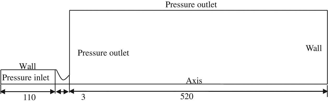
Geometry of computational region.
Material property
During the high temperature erosion, the particles carried by gas mixture include: Al2O3, CaO, MgO and unburned carbon particles. In this work, the CaO particles are selected as the erosion particles. The detailed material properties of CaO are given in Table 1. It should be noted that, some assumptions are adopted in the erosion process: (1) The collisions between particles are not taken into account; (2) There is no fracture occurs in the particle as the particle impact on the wall; (3) The volume of particles is neglible. The initialization parameters of particle are shown in Table 2.
Thermal properties of Cao.
| Density (kg/m3) | Ratio of specific heat capacities (J/kg· K) | Heat conductivity (W/m· K) |
|---|---|---|
| 3320 | 783 | 2.25 |
Initial parameters of particle.
| Initial conditions | |
|---|---|
| Injection type | Perpendicular to surface |
| Diameter distribution | Uniform distribution |
| X-Velocity(m/s) | 5 |
| Y-Velocity (m/s) | −30 |
| Diameter (µm) | 10, 20, 50, 75 |
| Temperature (K) | 300 |
| Mass flow rate (kg/s) | 0.001 |
Meshing and boundary conditions
The grid is generated by the GAMBIT of FLUENT. The structured quadrilateral grid is adopted to the model and the finite element model of the geometric which shows that the grid has 69,005 total nodes and 135,590 total cells in Figure 3. Finer grid is used around the drastic change zones (such as, the inlet of nozzle, outlet and the central zone of jet flow) in the flow field to improve the accuracy of simulation results. There are four different types of boundary conditions: the inlet boundary, the outlet boundary, the solid wall boundary and the axisymmetric boundary. The total temperature (Tt,inlet), total pressure (Pt,inlet) and static pressure (Ps,inlet) are fixed at the inlet boundary; the average static-pressure (Ps,outlet) is given at the outlet boundary; at the solid wall, the no-slip boundary condition is adopted. The detailed parameters of boundary conditions are presented in Table 3.
The detailed parameters of boundary conditions.
| Mach numbers | Total temperature(K) | Total pressure(MPa) | Static-pressure(MPa) | Average static-pressure(Pa) | Turbulence intensity |
|---|---|---|---|---|---|
| 0.3 | 1600 | 1.21 | 1.10 | 1.013×10⁵ | 4.9% |
| 0.5 | 1600 | 1.34 | 1.24 | 1.013×10⁵ | 5.09% |
| 0.9 | 1600 | 1.87 | 1.76 | 1.013×10⁵ | 5.19% |

Grid of geometry region (a) grid of computational region (b) grid of the nozzle.
Results and discussions
The evolution of temperature
Figure 4 shows the contours of temperature distribution of gas stream in the inlet condition of Mach 0.3. It can be seen that the temperature of the gas stream falls drastically as the gas stream ejecting from the Laval nozzle. This is because that the intense interaction between high energy gas stream and air leads to the heat loss. Moreover, the more distant the gas stream far away from the spray gun, the lower the temperature value is. In addition, the temperature distributions of gas stream along the axial direction at different Mach number are given in Figure 5. It is found that the temperature of gas stream drops more quickly at the outlet of the nozzle with the increase of the Mach number. This is attributed to that the interaction between gas stream and air is more intense at the high Mach number, which results in much more energy loss.

The contours of gas temperature at Mach 0.3.

Gas temperature profiles from Mach 0.3 to Mach 0.9.
Comparisons of temperature distribution of different particles along the axial direction in the condition of different Mach number are shown in Figure 6. The erosion particle is injected through the spray gun and heated by the gas stream. The temperature variation of particle is similar to that of gas stream. The temperature of particle follows that of gas stream temperature. However, due to the heat transfer delay between the high temperature gas stream and particle, the decrease of particle temperature does not synchronize with that of gas stream temperature. Furthermore, the particle temperature is even higher than that of the gas stream as the distance is far from the spray gun. For the case of Mach 0.3, the particle temperature follows the gas stream temperature as the particle size is small. The particle temperature rises and then drops quickly. The highest temperature of particle is approximately 1513 K as its size is 10 μm. With the increase of particle size, the heating rate of particle slows down. As the particle size reaches 75 μm, the highest temperature of particle is 820 K. Furthermore, with the increase of particle size, there is an obvious asynchronism of temperature variation between the high temperature gas stream and particle. As the particle size is more than 50 μm, the particle temperature rises with the distance from the spray gun, whereas the gas stream temperature drops when the distance is far from the spray gun. Temperature distribution of different particle size along the axial direction are almost is irrelevant to the Mach number. The effect of Mach number on the temperature distribution of different particle size can be neglected.

Gas temperature versus to particle temperature for different size particles at different Mach numbers: (a) Mach 0.3, (b) Mach 0.5 and (c) Mach 0.9.
The evolution of velocity
The contours of velocity distribution of gas stream at Mach 0.3 is shown in Figure 7. As the gas stream passes through the Laval nozzle, the velocity of gas stream increases drastically and is up to its maximum caused by the special structural design of nozzle, then drops quickly from the nozzle. When the distance is far from the Laval nozzle, the velocity is rather minimal due to the energy dissipation of interaction between the gas stream and air flow. Velocity distribution of flow field along the axial direction is smooth, which is seen to be streamlined. Velocity distribution of gas stream along the axial direction at Mach 0.3, Mach 0.5 and Mach 0.9 are shown in Figure 8. It can be seen that the gas velocity distribution at different Mach number are similar but the magnitude are different. The difference in Mach numbers affects the magnitude of the initial velocity of gas stream. Owing to the acceleration effect of Laval nozzle, the gas stream velocity rises sharply. The larger the Mach numbers, the more obvious the acceleration effect is. As the Mach number is 0.3, the maximum gas stream velocity is 250 m/s. When the Mach number reaches 0.9, the gas stream velocity rises to 550 m/s. While as the distance is far away from the Laval nozzle, the gas stream falls quickly with the increase of Mach number. Finally, when the distance far from the Laval nozzle reaches 0.52 m, the gas stream velocity are all close to zero.

The contours of gas velocity at Mach 0.3.

Plot of gas velocity at Mach 0.3–Mach 0.9.
Based on the simulation of the coupled interaction between the gas stream and the particle, velocity distributions of gas stream and particle along the axial direction at Mach 0.3, Mach 0.5 and Mach 0.9 can be obtained (see Figure 9). The erosion particles are added through the spray gun and accelerated by the gas stream due to the momentum transfer, then the mixture of gas and particle are injected by the spray gun. The velocity has two features: (1) The velocity of gas stream is larger than that of the velocity of particle before the mixture of gas and particle are injected by the spray gun. As the distance is far away from the Laval nozzle, the particle velocity is even larger than that of gas stream. This phenomenon is much more obvious with increasing of the Mach number; (2) The accelerated velocity rises with the increase of the Mach number and the acceleration distance of particles is longer. This is associated with the results of the force imposed on the particle. Furthermore, the smaller the particle size, the larger the accelerated velocity is.

Gas velocity versus to particle velocity for different size particles at different Mach numbers: (a) Mach 0.3, (b) Mach 0.5 and (c) Mach 0.9.
The contours of velocity distribution of particle are shown in Figure 10. It shows that as the distance from the Laval nozzle reach 50 and 110 μm, the particle velocity are 148 m/s and 153 m/s at Mach 0.3, 198 m/s and 212 m/s at Mach 0.5, respectively. The simulations of particle velocity are compared with that obtained by the erosion experiment. It is found that the simulation results are comparable to the experimental values (see Figure 11), which confirms the validity of this simulation.

10 um particle distribution of velocity at different Mach number: (a) Mach 0.3 and (b) Mach 0.5.
![Figure 11: Representative photograph of the particle velocity (a) Mach 0.3 and (b) Mach 0.5 [11].](/document/doi/10.1515/htmp-2017-0172/asset/graphic/j_htmp-2017-0172_fig_011.jpg)
Representative photograph of the particle velocity (a) Mach 0.3 and (b) Mach 0.5 [11].
Conclusions
A 2D numerical model of burner has been developed to investigate the temperature and velocity distribution regularities by a fluid-solid coupling method. A reasonable turbulence model (realizable
(1) A non-uniform distribution of temperature appears in different positions of the central axis. There is about 600 to 800 K for temperature difference of gas stream between the entrance and distal jet at Mach 0.3–Mach 0.5, which revealed that the temperature fall along the central axis, especially falling with the increases of Mach number. Also particles temperature is affected obviously by the gas stream and particle size.
(2) Due to the special mechanical structure of Laval nozzle, the velocity of gas stream has a surge in the throat of nozzle. Moreover, the maximum of velocity increase with the increase of Mach number. The velocity is trend to a approximated value in the distal end. Also, the velocity of particles is affected obviously by the gas stream and their own particle size.
(3) The simulation results reveal the variations of velocity and temperature of gas stream and particle under the erosion process, and provide a theoretical guidance for the subsequent gun design and feed of simulation experiment.
Acknowledgements
This work was supported by the National Natural Science Foundationof China (grant No. 11602211), the Hunan Provincial Natural Science Foundation of China (Grant No. 2017JJ3307), and the Outstanding Youth Foundation of Hunan Provincial Education Department (Grant No. 16B249).
References
[1] N.P. Padture, M. Gell and E.H. Jordan, Science, 296 (2002) 280–284.10.1126/science.1068609Search in Google Scholar
[2] W. Lih, E. Chang, B. Wu and C. Chao, Oxid Met., 36 (1991) 221–238.10.1007/BF00662963Search in Google Scholar
[3] R.A. Miller, J. Therm. Spray Technol., 6 (1997) 35–42.10.1007/BF02646310Search in Google Scholar
[4] L. Yang, Y. Zhou, W. Mao and Q. Liu, Surf. Rev. Lett., 14 (2007) 935–943.10.1142/S0218625X07010494Search in Google Scholar
[5] L. Yang, Y. Zhou and C. Lu, Acta Mater., 59 (2011) 6519–6529.10.1016/j.actamat.2011.06.018Search in Google Scholar
[6] D. Clarke and C. Levi, Annu Rev Mater Res., 33 (2003) 383–417.10.1146/annurev.matsci.33.011403.113718Search in Google Scholar
[7] A.G. Evans, D.R. Clarke and C.G. Levi, J. Eur. Ceram. Soc., 28 (2008) 1405–1419.10.1016/j.jeurceramsoc.2007.12.023Search in Google Scholar
[8] A. Rabiei and A. Evans, Acta Mater., 48 (2000) 3963–3976.10.1016/S1359-6454(00)00171-3Search in Google Scholar
[9] R.A. Miller, Surf. Coat. Technol., 30 (1987) 1–11.10.1016/0257-8972(87)90003-XSearch in Google Scholar
[10] J. Aktaa, K. Sfar and D. Munz, Acta Mater., 53 (2005) 4399–4413.10.1016/j.actamat.2005.06.003Search in Google Scholar
[11] D. Zhu, R.A. Miller and M.A. Kuczmarski, NASA/TM-2010-215669, 2010.Search in Google Scholar
[12] R. Vaßen, F. Cernuschi, G. Rizzi, A. Scrivani, N. Markocsan, L. Östergren, A. Kloosterman, R. Mevrel, J. Feist and J. Nicholls, Adv. Eng. Mater., 10 (2008) 907–921.10.1002/adem.200800015Search in Google Scholar
[13] R. Wanhill, A. Mom, H. Hersbach, G. Kool and J. Boogers, Natl. Lucht Ruimtevaartlab. Rep., 7 (1989) 202–211.10.1080/02619180.1989.11753438Search in Google Scholar
[14] M. Kirschner, T. Wobst, B. Rittmeister and C. Mundt, J. Eng. Gas Turbines Power., 137 (2015) 032101.10.1115/1.4028469Search in Google Scholar
[15] R.A. Miller and M.A. Kuczmarski, J. Test. Eval., 42 (2014) 648–658.10.1520/JTE20120303Search in Google Scholar
[16] A. Evans, N. Fleck, S. Faulhaber, N. Vermaak, M. Maloney and R. Darolia, Wear, 260 (2006) 886–894.10.1016/j.wear.2005.05.005Search in Google Scholar
[17] D. Cheng, Q. Xu, E. Lavernia and G. Trapaga, Metall Mater Trans B., 32 (2001) 525–535.10.1007/s11663-001-0037-3Search in Google Scholar
[18] S. Kamnis, S. Gu and N. Zeoli, Surf. Coat. Technol., 202 (2008) 2715–2724.10.1016/j.surfcoat.2007.10.006Search in Google Scholar
[19] S. Kamnis and S. Gu, Chem. Eng. Sci., 61 (2006) 5427–5439.10.1016/j.ces.2006.04.005Search in Google Scholar
[20] R.A. Miller, M.A. Kuczmarski and D. Zhu, NASA/TM-2011-217008, 2011.10.1155/2011/837921Search in Google Scholar
[21] R. Eymard, T. Gallouët and R. Herbin, Handb.Numer.Anal., 7 (2000) 713–1018.10.1016/S1570-8659(00)07005-8Search in Google Scholar
[22] L. Hylton, M. Mihelc, E. Turner, D. Nealy and R. York, NASA-CR-168015, 1983.Search in Google Scholar
[23] D. Zhu and R.A. Miller, Int. J. Appl. Ceram. Technol., 1 (2004) 86–94.10.1111/j.1744-7402.2004.tb00158.xSearch in Google Scholar
[24] S. Gu and S. Kamnis, Surf. Coat. Technol., 203 (2009) 3485–3490.10.1016/j.surfcoat.2009.05.024Search in Google Scholar
[25] S. Kamnis, S. Gu, T. Lu and C. Chen, Comput. Mater. Sci., 43 (2008) 1172–1182.10.1016/j.commatsci.2008.03.015Search in Google Scholar
[26] E. Walhorn, A. Kölke, B. Hübner and D. Dinkler, Comput Struct., 83 (2005) 2100–2111.10.1016/j.compstruc.2005.03.010Search in Google Scholar
[27] S. Kamnis, S. Gu, T.J. Lu and C. Chen, Comput. Mater. Sci., 46 (2008) 1038–1043.10.1016/j.commatsci.2009.05.009Search in Google Scholar
[28] N. Zeoli and S. Gu, Comput. Mater. Sci., 42 (2008) 245–258.10.1016/j.commatsci.2007.07.013Search in Google Scholar
[29] M. Li and P.D. Christofides, Chem. Eng. Sci., 61 (2006) 6540–6552.10.1016/j.ces.2006.05.050Search in Google Scholar
[30] B.A. Schrefler, P. Brunello, D. Gawin, C.E. Majorana and F. Pesavento, Comput. Mech., 29 (2002) 43–51.10.1007/s00466-002-0318-ySearch in Google Scholar
[31] C.H. Zhang, Y. Liu, R.M.C. So and N. Phan-Thien, Comput. Mech., 29 (2002) 422–429.10.1007/s00466-002-0352-9Search in Google Scholar
[32] S.A.J. Morsi and A.J. Alexander, J. Fluid Mech., 55 (1972) 193–208.10.1017/S0022112072001806Search in Google Scholar
[33] W.Y. Li and C.J. Li, J. Therm. Spray Technol., 14 (2005) 391–396.10.1361/105996305X59404Search in Google Scholar
[34] B. Xu and A. Yu, Chem. Eng. Sci., 52 (1997) 2785–2809.10.1016/S0009-2509(97)00081-XSearch in Google Scholar
© 2019 Walter de Gruyter GmbH, Berlin/Boston
This work is licensed under the Creative Commons Attribution 4.0 Public License.
Articles in the same Issue
- Frontmatter
- Review Article
- Research on the Influence of Furnace Structure on Copper Cooling Stave Life
- Influence of High Temperature Oxidation on Hydrogen Absorption and Degradation of Zircaloy-2 and Zr 700 Alloys
- Correlation between Travel Speed, Microstructure, Mechanical Properties and Wear Characteristics of Ni-Based Hardfaced Deposits over 316LN Austenitic Stainless Steel
- Factors Influencing Gas Generation Behaviours of Lump Coal Used in COREX Gasifier
- Experiment Research on Pulverized Coal Combustion in the Tuyere of Oxygen Blast Furnace
- Phosphate Capacities of CaO–FeO–SiO2–Al2O3/Na2O/TiO2 Slags
- Microstructure and Interface Bonding Strength of WC-10Ni/NiCrBSi Composite Coating by Vacuum Brazing
- Refill Friction Stir Spot Welding of Dissimilar 6061/7075 Aluminum Alloy
- Solvothermal Synthesis and Magnetic Properties of Monodisperse Ni0.5Zn0.5Fe2O4 Hollow Nanospheres
- On the Capability of Logarithmic-Power Model for Prediction of Hot Deformation Behavior of Alloy 800H at High Strain Rates
- 3D Heat Conductivity Model of Mold Based on Node Temperature Inheritance
- 3D Microstructure and Micromechanical Properties of Minerals in Vanadium-Titanium Sinter
- Effect of Martensite Structure and Carbide Precipitates on Mechanical Properties of Cr-Mo Alloy Steel with Different Cooling Rate
- The Interaction between Erosion Particle and Gas Stream in High Temperature Gas Burner Rig for Thermal Barrier Coatings
- Permittivity Study of a CuCl Residue at 13–450 °C and Elucidation of the Microwave Intensification Mechanism for Its Dechlorination
- Study on Carbothermal Reduction of Titania in Molten Iron
- The Sequence of the Phase Growth during Diffusion in Ti-Based Systems
- Growth Kinetics of CoB–Co2B Layers Using the Powder-Pack Boriding Process Assisted by a Direct Current Field
- High-Temperature Flow Behaviour and Constitutive Equations for a TC17 Titanium Alloy
- Research on Three-Roll Screw Rolling Process for Ti6Al4V Titanium Alloy Bar
- Continuous Cooling Transformation of Undeformed and Deformed High Strength Crack-Arrest Steel Plates for Large Container Ships
- Formation Mechanism and Influence Factors of the Sticker between Solidified Shell and Mold in Continuous Casting of Steel
- Casting Defects in Transition Layer of Cu/Al Composite Castings Prepared Using Pouring Aluminum Method and Their Formation Mechanism
- Effect of Current on Segregation and Inclusions Characteristics of Dual Alloy Ingot Processed by Electroslag Remelting
- Investigation of Growth Kinetics of Fe2B Layers on AISI 1518 Steel by the Integral Method
- Microstructural Evolution and Phase Transformation on the X-Y Surface of Inconel 718 Ni-Based Alloys Fabricated by Selective Laser Melting under Different Heat Treatment
- Characterization of Mn-Doped Co3O4 Thin Films Prepared by Sol Gel-Based Dip-Coating Process
- Deposition Characteristics of Multitrack Overlayby Plasma Transferred Arc Welding on SS316Lwith Co-Cr Based Alloy – Influence ofProcess Parameters
- Elastic Moduli and Elastic Constants of Alloy AuCuSi With FCC Structure Under Pressure
- Effect of Cl on Softening and Melting Behaviors of BF Burden
- Effect of MgO Injection on Smelting in a Blast Furnace
- Structural Characteristics and Hydration Kinetics of Oxidized Steel Slag in a CaO-FeO-SiO2-MgO System
- Optimization of Microwave-Assisted Oxidation Roasting of Oxide–Sulphide Zinc Ore with Addition of Manganese Dioxide Using Response Surface Methodology
- Hydraulic Study of Bubble Migration in Liquid Titanium Alloy Melt during Vertical Centrifugal Casting Process
- Investigation on Double Wire Metal Inert Gas Welding of A7N01-T4 Aluminum Alloy in High-Speed Welding
- Oxidation Behaviour of Welded ASTM-SA210 GrA1 Boiler Tube Steels under Cyclic Conditions at 900°C in Air
- Study on the Evolution of Damage Degradation at Different Temperatures and Strain Rates for Ti-6Al-4V Alloy
- Pack-Boriding of Pure Iron with Powder Mixtures Containing ZrB2
- Evolution of Interfacial Features of MnO-SiO2 Type Inclusions/Steel Matrix during Isothermal Heating at Low Temperatures
- Effect of MgO/Al2O3 Ratio on Viscosity of Blast Furnace Primary Slag
- The Microstructure and Property of the Heat Affected zone in C-Mn Steel Treated by Rare Earth
- Microwave-Assisted Molten-Salt Facile Synthesis of Chromium Carbide (Cr3C2) Coatings on the Diamond Particles
- Effects of B on the Hot Ductility of Fe-36Ni Invar Alloy
- Impurity Distribution after Solidification of Hypereutectic Al-Si Melts and Eutectic Al-Si Melt
- Induced Electro-Deposition of High Melting-Point Phases on MgO–C Refractory in CaO–Al2O3–SiO2 – (MgO) Slag at 1773 K
- Microstructure and Mechanical Properties of 14Cr-ODS Steels with Zr Addition
- A Review of Boron-Rich Silicon Borides Basedon Thermodynamic Stability and Transport Properties of High-Temperature Thermoelectric Materials
- Siliceous Manganese Ore from Eastern India:A Potential Resource for Ferrosilicon-Manganese Production
- A Strain-Compensated Constitutive Model for Describing the Hot Compressive Deformation Behaviors of an Aged Inconel 718 Superalloy
- Surface Alloys of 0.45 C Carbon Steel Produced by High Current Pulsed Electron Beam
- Deformation Behavior and Processing Map during Isothermal Hot Compression of 49MnVS3 Non-Quenched and Tempered Steel
- A Constitutive Equation for Predicting Elevated Temperature Flow Behavior of BFe10-1-2 Cupronickel Alloy through Double Multiple Nonlinear Regression
- Oxidation Behavior of Ferritic Steel T22 Exposed to Supercritical Water
- A Multi Scale Strategy for Simulation of Microstructural Evolutions in Friction Stir Welding of Duplex Titanium Alloy
- Partition Behavior of Alloying Elements in Nickel-Based Alloys and Their Activity Interaction Parameters and Infinite Dilution Activity Coefficients
- Influence of Heating on Tensile Physical-Mechanical Properties of Granite
- Comparison of Al-Zn-Mg Alloy P-MIG Welded Joints Filled with Different Wires
- Microstructure and Mechanical Properties of Thick Plate Friction Stir Welds for 6082-T6 Aluminum Alloy
- Research Article
- Kinetics of oxide scale growth on a (Ti, Mo)5Si3 based oxidation resistant Mo-Ti-Si alloy at 900-1300∘C
- Calorimetric study on Bi-Cu-Sn alloys
- Mineralogical Phase of Slag and Its Effect on Dephosphorization during Converter Steelmaking Using Slag-Remaining Technology
- Controllability of joint integrity and mechanical properties of friction stir welded 6061-T6 aluminum and AZ31B magnesium alloys based on stationary shoulder
- Cellular Automaton Modeling of Phase Transformation of U-Nb Alloys during Solidification and Consequent Cooling Process
- The effect of MgTiO3Adding on Inclusion Characteristics
- Cutting performance of a functionally graded cemented carbide tool prepared by microwave heating and nitriding sintering
- Creep behaviour and life assessment of a cast nickel – base superalloy MAR – M247
- Failure mechanism and acoustic emission signal characteristics of coatings under the condition of impact indentation
- Reducing Surface Cracks and Improving Cleanliness of H-Beam Blanks in Continuous Casting — Improving continuous casting of H-beam blanks
- Rhodium influence on the microstructure and oxidation behaviour of aluminide coatings deposited on pure nickel and nickel based superalloy
- The effect of Nb content on precipitates, microstructure and texture of grain oriented silicon steel
- Effect of Arc Power on the Wear and High-temperature Oxidation Resistances of Plasma-Sprayed Fe-based Amorphous Coatings
- Short Communication
- Novel Combined Feeding Approach to Produce Quality Al6061 Composites for Heat Sinks
- Research Article
- Micromorphology change and microstructure of Cu-P based amorphous filler during heating process
- Controlling residual stress and distortion of friction stir welding joint by external stationary shoulder
- Research on the ingot shrinkage in the electroslag remelting withdrawal process for 9Cr3Mo roller
- Production of Mo2NiB2 Based Hard Alloys by Self-Propagating High-Temperature Synthesis
- The Morphology Analysis of Plasma-Sprayed Cast Iron Splats at Different Substrate Temperatures via Fractal Dimension and Circularity Methods
- A Comparative Study on Johnson–Cook, Modified Johnson–Cook, Modified Zerilli–Armstrong and Arrhenius-Type Constitutive Models to Predict Hot Deformation Behavior of TA2
- Dynamic absorption efficiency of paracetamol powder in microwave drying
- Preparation and Properties of Blast Furnace Slag Glass Ceramics Containing Cr2O3
- Influence of unburned pulverized coal on gasification reaction of coke in blast furnace
- Effect of PWHT Conditions on Toughness and Creep Rupture Strength in Modified 9Cr-1Mo Steel Welds
- Role of B2O3 on structure and shear-thinning property in CaO–SiO2–Na2O-based mold fluxes
- Effect of Acid Slag Treatment on the Inclusions in GCr15 Bearing Steel
- Recovery of Iron and Zinc from Blast Furnace Dust Using Iron-Bath Reduction
- Phase Analysis and Microstructural Investigations of Ce2Zr2O7 for High-Temperature Coatings on Ni-Base Superalloy Substrates
- Combustion Characteristics and Kinetics Study of Pulverized Coal and Semi-Coke
- Mechanical and Electrochemical Characterization of Supersolidus Sintered Austenitic Stainless Steel (316 L)
- Synthesis and characterization of Cu doped chromium oxide (Cr2O3) thin films
- Ladle Nozzle Clogging during casting of Silicon-Steel
- Thermodynamics and Industrial Trial on Increasing the Carbon Content at the BOF Endpoint to Produce Ultra-Low Carbon IF Steel by BOF-RH-CSP Process
- Research Article
- Effect of Boundary Conditions on Residual Stresses and Distortion in 316 Stainless Steel Butt Welded Plate
- Numerical Analysis on Effect of Additional Gas Injection on Characteristics around Raceway in Melter Gasifier
- Variation on thermal damage rate of granite specimen with thermal cycle treatment
- Effects of Fluoride and Sulphate Mineralizers on the Properties of Reconstructed Steel Slag
- Effect of Basicity on Precipitation of Spinel Crystals in a CaO-SiO2-MgO-Cr2O3-FeO System
- Review Article
- Exploitation of Mold Flux for the Ti-bearing Welding Wire Steel ER80-G
- Research Article
- Furnace heat prediction and control model and its application to large blast furnace
- Effects of Different Solid Solution Temperatures on Microstructure and Mechanical Properties of the AA7075 Alloy After T6 Heat Treatment
- Study of the Viscosity of a La2O3-SiO2-FeO Slag System
- Tensile Deformation and Work Hardening Behaviour of AISI 431 Martensitic Stainless Steel at Elevated Temperatures
- The Effectiveness of Reinforcement and Processing on Mechanical Properties, Wear Behavior and Damping Response of Aluminum Matrix Composites