Microstructure and Mechanical Properties of Thick Plate Friction Stir Welds for 6082-T6 Aluminum Alloy
-
Zhimin Liang


Abstract
6082-T6 aluminum alloy plate with thickness of 42mm was butt welded by friction stir welding (FSW) from two sides. The microstructures of the joints exhibited different grain sizes because of unequal frictional heating and plastic flow during FSW process. The transition from the heat affected zone (HAZ) to the nugget zone (NZ) in thermos-mechanical affected zone of advancing side (AS-TMAZ) was more sudden than thermos-mechanical affected zone of retreating side (RS-TMAZ). Kissing bond (KB) defect throughout the entire FSW joint was displayed both at the grain boundary and in the interior of the grain with semi-continuous bands. KB had no direct effect on tensile properties. Vickers hardness of the FSW joint was lower than the BM because its high heat input, dissolved and coarsened precipitates and little to the grain size after FSW. Hardness distribution of double-sided welding joint showed X-shaped area softening characteristics, that is to say the lowest hardness was the junction of two welding joint of NZ and the junction of TMAZ and HAZ. The tensile fracture position occurred in the lowest hardness region of the FSW joint, and it did not occur in the KB defect position.
Introduction
The Al-Mg-Si alloys are commonly used for structural applications within the automotive, train and shipbuilding industry due to its excellent formability, good corrosion resistance and relative high mechanical properties. The 6082 aluminum alloy, as one type of these alloys, has been used in high-speed train manufacturing in China. When the conventional fusion welding methods were used to joint the alloy, a series of serious problems may appear including the formation of porosity, large welding deformation and high residual stresses [1]. Friction stir welding (FSW), which is a solid-state joining technique invented in 1991 by The Welding Institute (TWI), has many attractive advantages compared with the fusion welding processes, for example avoid of porosity, reduced deformation and decreased residual stresses [2].
The FSW joint is usually composed of four distinct zones, the base metal (BM), thermo-mechanical affected zone (TMAZ), the heat affected zone (HAZ), and the nugget zone (NZ). The BM is inevitably subject to additional thermal effects, but this is not enough to change its mechanical properties or microstructure. For heat-treatable aluminum alloys, the temperature needs to exceed 250℃ to treat the area as HAZ [3]. During the FSW, the NZ temperature can reach over 500℃. This zone showed a very fine grain structure [4]. However, for thick plate joint, the microstructure of NZ along the thickness direction is quite inhomogeneous [5]. It’s important to study the organizational changes in its thickness. For 6XXX alloys, β′ and β″ precipitations contribute mostly to strength and hardness improving [6]. The AS temperature is 5–10 K higher than the RS temperature [7].
Recently, the “kissing bond (KB)”, or “lazy S” and “zigzag line” was generally found in the etched cross-section of FSW joint [8, 9]. Sato investigated that KB particles were Al2O3 oxide particles with an amorphous structure, which did not affect the root-bend property of the FSW joint [8]. When the FSW joint is not defective, the tensile strength of the joint is related to the hardness distribution. However, the tensile strength of FSW joint with KB defect inside the stir zone was much lower than that of the sound FSW joint [10]. The tensile fracture examination exposed a series of severe “scalloping” appearance in the joint with continuous KB flaw, while the sound FSW exhibited fine dimples [10]. Whether KB affected mechanical properties was required further study.
With the increase in the industrial application of aluminum alloy thick plates, especially in high-speed train, the comprehensive microstructure evolution and mechanical properties research are more significant. In this paper, we analyzed the microstructure and mechanical properties in friction stir double-sided butt welding of 6082-T6aluminum alloys with thickness of 42mm by experimental investigation including microstructure examination, Vickers hardness and TEM. The experimental parameters and conclusions have practical significance for the actual production.
Materials and experimental procedures
Materials and welding method
The chemical composition of 6082-T6 aluminum alloy was shown in Table 1. The test specimens were couples of 42mm× 150mm× 500 mm. Prior to the welding, the oxide layer close to FSW groove was mechanically removed. The zero-gap butt joint configuration was obtained by special mechanical clamps. The FSW joint was double-side butt welded joint. The welding parameters were listed in Table 2. The welding tool was also shown in Figure 1.
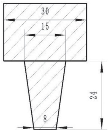
The diagram of welding tool (unit: mm).
Chemical composition of the alloy (wt.%).
| Si | Mg | Mn | Fe | Cu | Al |
|---|---|---|---|---|---|
| 1.05 | 0.61 | 0.45 | 0.22 | 0.021 | Bal. |
Welding parameters.
| Spindle speed (R/min) | Travel speed (mm/min) | Friction pressure (KN) | Tool motion |
|---|---|---|---|
| 400 | 110 | 1800 | Anticlockwise |
Microstructure and mechanical properties examination
Optical microscope was used to observe the microstructures in different zones on the top surface and the cross-section of the FSW joint. And the samples were etched using Keller’s etch.
Transmission electron microscopy (TEM) was used to observe the precipitate particles in different zones of the FSW joint. The TEM thin foils specimens were mechanically milled to 50 μm thickness using abrasive papers and electropolished using 70 vol. % methanol and 30 vol. % nitric acid solution at −30℃ with a voltage of 10 V. And the specific sampling positions were shown in Figure 4 (with the indexed number from 1to 7).
The locations of hardness testing points on the cross-section double-side FSW joint (unit: mm).
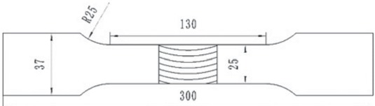
The dimensions of tensile test samples (unit: mm).
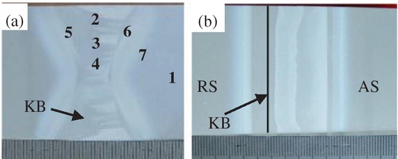
Macrostructure of the FSW joint: (a) cross-section: (1) BM (2) SAZ (3) Middle of NZ (4) Bottom of NZ (5) RS-TMAZ (6) AS-TMAZ (7) HAZ; (b) Top Surface: KB (kissing bond).
Vickers hardness (HV) measurements were performed through the FSW joint of cross-section at different depths. The Vickers hardness was measured on a polished surface of the weld, using 500 g load and loading time were 10 s, respectively. The distance between the two neighboring test points was 1mm to avoid possible interference of measurements. The locations of hardness points on the cross-section were shown in Figure 2.
The tensile tests were carried out at room temperature using a Zwick Z600 electronic tensile testing machine. The dimensions of tensile test samples are shown in Figure 3. There were three samples for the tensile test.
After testing, the fracture surfaces were examined using TESCAN-VEGAS scanning electron microscope (SEM).
Results and discussion
Microstructure observation
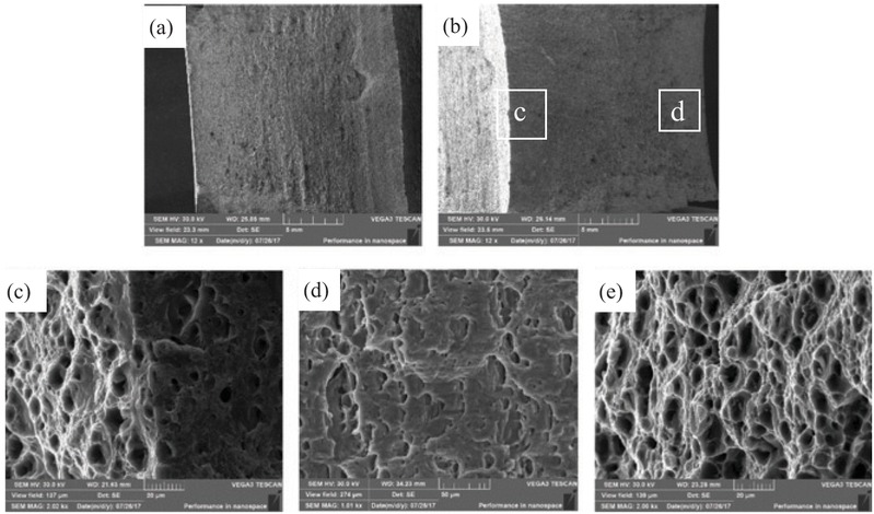
The macrostructure characterizations of the FSW joint were shown in Figure 4. The welded joint is divided into seven distinct regions along the cross-section including the shoulder-affected zone (SAZ), the middle of NZ, the bottom of NZ, thermomechanical affected zone of advancing side (AS-TMAZ), thermomechanical affected zone of retreating side (RS-TMAZ), the HAZ, and the base metal (BM), as shown in Figure 4(a). The macro-structure of the top surface of the FSW joint was shown in Figure 4(b). Figure 5 showed the microstructures of the cross-section and top of TMAZ in the FSW joint. The transition from the HAZ to NZ was more sudden on the AS-TMAZ (see Figure 5a, c) than the RS-TMAZ (see Figure 5b, c). It can be explained on the basis of the flow and thermal behavior of material model developed by Hamilton et al [6]. A sharp boundary develops on the AS-TMAZ as the rising flow from the work piece bottom and the downward flow from the work piece surface oppose one to another with very little cross flow [6]. And the model suggests that RS-TMAZ is strong material flow cross the boundary, so the RS-TMAZ boundary is diffused and gradual [11]. And there is a noticeable stir pattern on the advancing side in cross-section. Figure 6 showed microstructure of grain size distribution in the transverse cross–section of the FSW joint. This can be attributed to the degree of heat input and the concomitant grain growth [12]. Slightly coarser grains were observed in the BM (Gave = 7.24 μm) (see Figure 6a). Comparing the grain sizes of the SAZ (Gave = 5.37 μm), middle of NZ (Gave = 5.84 μm) and bottom of NZ (Gave = 2.51 μm), the bottom of NZ exhibited refined grains, most likely due to the impact of double stirring of the tool needle (see Figure 6b, c, d). The grain size of HAZ (Gave = 5.84 μm) was slightly coarser than that of AS-TMAZ (Gave = 3.50 μm) and was similar to that of RS-TMAZ (Gave = 5.78 μm) (see Figure 6e, f, g). The grain size on the RS-TMAZ was coarser than that on the AS-TMAZ. This was related to the flow and thermal behavior of material mentioned earlier.
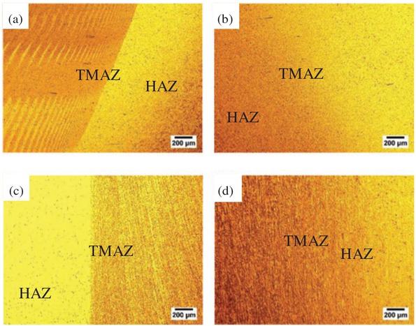
Microstructures of the TMAZ. (a) Cross-section of AS-TMAZ; (b) Cross-section of RS-TMAZ; (c) Top surface of AS-TMAZ; (d) Top surface of RS-TMAZ.
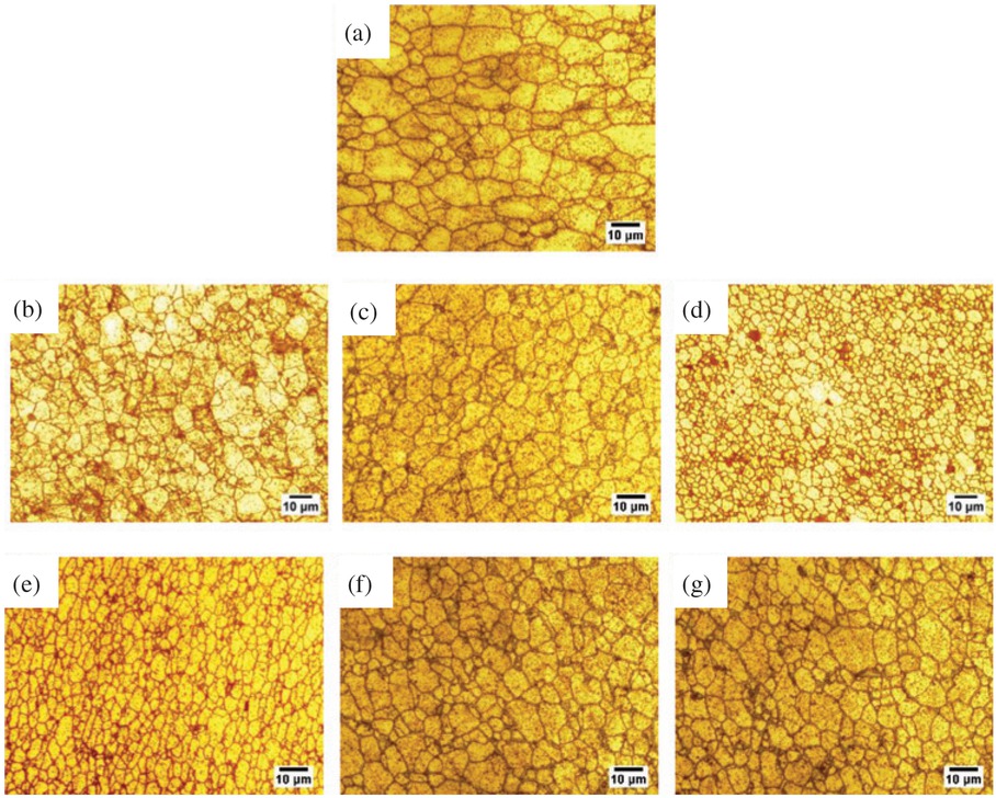
Microstructures of grain size distribution in the cross –section of the specimen: (a) BM (Gave = 7.24 μm); (b) SAZ (Gave = 5.37 μm); (c) Middle of NZ (Gave = 5.84 μm); (d) Bottom of NZ (Gave = 2.51 μm); (e) AS-TMAZ (Gave = 3.50 μm); (f) RS-TMAZ (Gave = 5.78 μm); (g) HAZ (Gave = 5.84 μm).
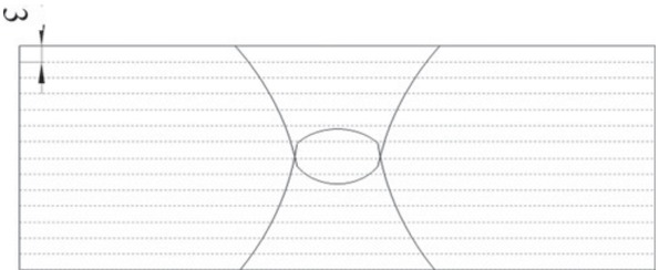
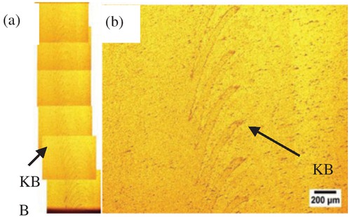
The zigzag line was the presence of oxide particles, which formed semi-continuous bands from the SAZ to the bottom of the NZ, known as KB. Overview image of KB was shown in Figure 4(a). The model of the KB was shown in Figure 7. The KB ran through the entire weld. Top surface of the FSW joint was the XY surface (see Figure 7), and KB was shown in Figure 8(a). Figure 8(b) showed the detail of KB with a zig-zag shape. The cross-section surface of the FSW joint was the XZ surface (see Figure 7). KB of the cross-section was shown in Figure 9. The width of the KB was not uniform. The KB in the cross-section changed complex and diverse. The complex change of the KB was closely related to plastic flow. Figure 10 showed the relationship between the position of KB and grain. Figure 10(a) showed the microstructure of a thinner position of KB line Figure 10(b) showed themicrostructure of a thicker position of KB line. It can be seen that the KB exist both at the grain boundary and in the interior of the grain with semi-continuous bands.
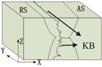
The model of the KB (kissing bond) line in space.
Kissing bond (KB) of XY surface of FSW joint. (a) Overview of kissing bond (KB); (b) Detail of kissing bond (KB).
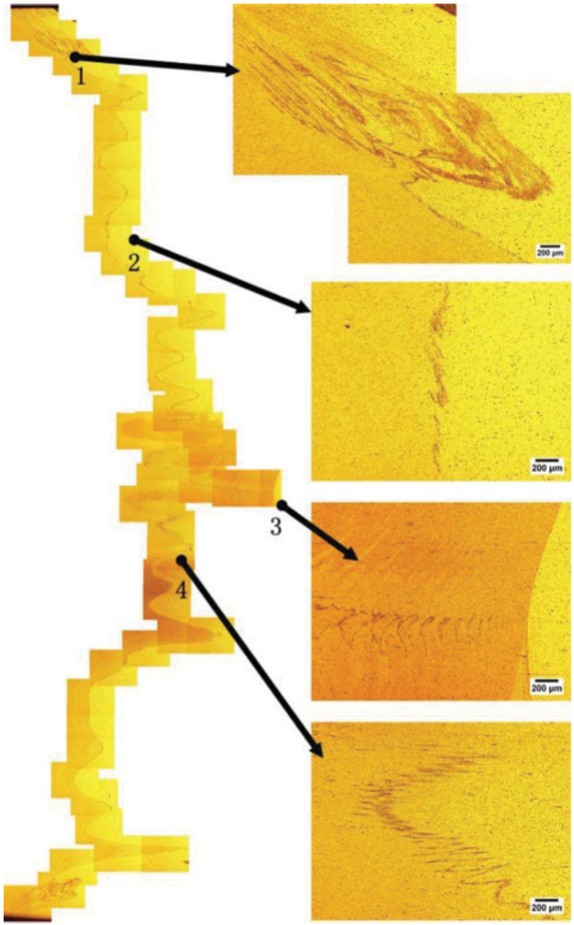
Kissing bond (KB) of XZ surface of FSW joint.
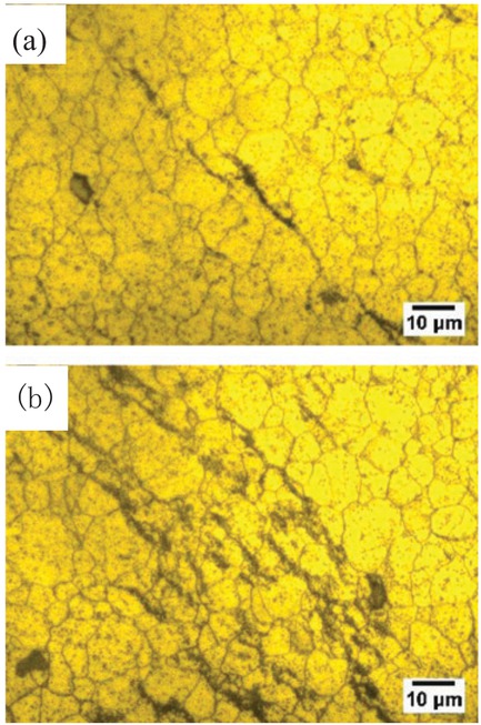
The relationship between the position of Kissing bond (KB) and grains. (a) Thinner position of KB line; (b) Thicker position of KB line.
TEM analysis
The locations of TEM thin foils were shown in Figure 4(a) (1 to 7 is the location of the TEM thin foils). Figure 11 presented TEM results obtained from the FSW joint. The BM contains high-density of needle-shaped precipitates β″ (average thickness is 3 nm) which were contributes to the hardness of the material (see Figure 11a). The precipitates β were often formed above 300°C [13]. The precipitates β was relatively coarsen and the enhancement effect was usually poor [13]. Comparing the thickness precipitates β of SAZ, middle of NZ and bottom of NZ, the precipitates β of bottom of NZ (average thickness is 16 nm) were slightly coarser than that of middle of NZ

Precipitate particles in the interior grain of: (a) BM; (b) SAM; (c) Middle of NZ; (d) Bottom of NZ; (e) AS-TMAZ; (f) RS-TMAZ; (g) HAZ.
(average thickness is 12 nm) and SAZ(average thickness is 10 nm) (see Figure 11b, c, d). The precipitates were also dissolved in FSW joints compared with BM. The AS-TMAZ had a grain structure with a relatively high density of dislocation pile-up (see Figure 11e). The sub-boundaries were observed in the grain boundary in RS-TMAZ (see Figure 11f).
Vickers hardness
The Vickers hardness measured across the FSW joint was shown in Figure 12. Hardness distribution of double-sided welding joint showed X-shaped area softening characteristics. The difference in hardness was observed in FSW joint. The lowest hardness was the junction of two bead of NZ and the junction of TMAZ and HAZ (ranged from 48 to 70 HV). The hardness along the weld thickness direction in the SAZ, the middle of NZ and the bottom of NZ, appeared lower than previous ones. The hardness increased from the HAZ to the BM (ranged from 100 to 115 HV). For the 6XXX alloys, precipitate hardening is the main strengthening mechanism and the strength can be measured by hardness test. The FSW process tends to soften the alloys because of the high heat input dissolved and coarsened precipitates [14]. Sato Studied the relationship between hardness and precipitation distribution in AA6063-T5, taking into account the effect of grain size during the FSW [15]. The results showed that the hardness was mainly affected by precipitation hardening, and little effect to the grain size after FSW. Figures 6 and 12 showed that the grain size of the bottom of NZ was refine, but the hardness was low. The precipitates β of the bottom of NZ were slightly coarser than that in the middle of NZ and SAZ. That was to say, the grain size had little effect on the hardness of the FSW. The main factor affecting hardness was the precipitates.
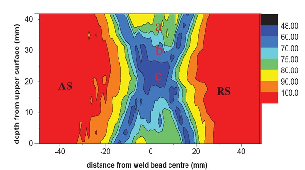
Map of Vickers hardness of FSW joint. Note: (a) SAZ; (b) Middle of NZ; (c) Bottom of NZ.
Tensile test
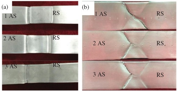
Macroscopic fractured surfaces of the FSW joint after tensile tests were shown in Figure 13. Typical mechanical properties of FSW joint were listed in Table 3. The
Macroscopic observations for fractured surfaces of the FSW joint.
Tensile tests.
| Tensile data | Ultimate tensile strength (MPa) | 0.2% yield strength (MPa) | Percent elongation at fracture (%) |
|---|---|---|---|
| 1 | 224.9 | 145.8 | 6.1 |
| 2 | 226.3 | 146.2 | 5.9 |
| 3 | 225.7 | 144.9 | 6.1 |
| Average | 225.6 | 145.6 | 6.0 |
average tensile strength was 225.6 MPa and the average elongation was 6%. Failure occurred in the FSW joint for two types of samples. The FSW joint exhibited a ductile shear fracture in the sample 1、2、3 fracture with a shear angle of 45° in the HAZ near the TMAZ. The tensile fracture position occurred in the lowest hardness region of the FSW joint. It did not occur in the KB position. KB line had no direct effect on the location of the fracture. Figures 14 and 15 showed the SEM images of the test fracture surface of the sample 1, 2 of FSW joint. The dimples of the fractured surface indicated that the fracture was the ductile fracture. However, there were also brittle fracture characteristics in the fracture surface in Figures 14(e) and 15(d).
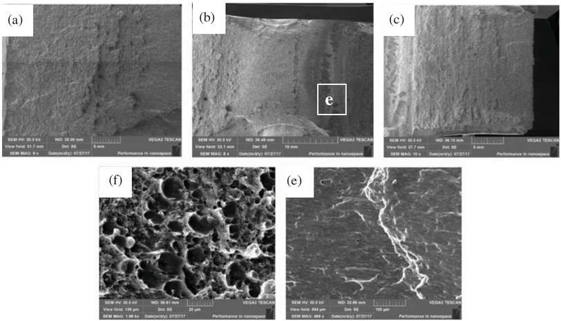
SEM images of test fracture surface of the sample 1. (a) Top surface area; (b) Centre area; (c) Bottom surface area.
SEM images of test fracture surface of the specimen 2: (a) Top surface area; (b) Centre and bottom surface area.
Conclusions
The mechanical and metallurgical behavior of 6082-T6 aluminum alloy was studied in this paper. The micro-structures exhibited different grain sizes because of the frictional heating and the plastic flow during FSW process. Slightly coarser grains were observed in the BM. The grain size of HAZ was slightly coarser than that of AS-TMAZ but similar to that of RS-TMAZ. The transition from the HAZ to NZ was more sudden on the AS-TMAZ than the RS-TMAZ; FSW joint had KB defect. The KB ran through the entire weld. It can be seen that the KB exist both at the grain boundary and in the interior of the grain with semi-continuous bands. KB had no direct effect on tensile properties.
TEM showed that high density of needle-shaped precipitates β″ were observed in the BM. β″ precipitations contribute BM hardness improving. The precipitates β of bottom of NZ were slightly coarser than that of middle of NZ and SAZ. Coarse precipitates β enhancement effect was poor.
The Vickers hardness of the welded zones was lower than the BM because of the high heat input dissolved and coarsened the precipitates. The lowest hardness was the
junction of two welding joint of NZ and the junction of TMAZ and HAZ.
According to the microstructure and Vickers hardness experiments, we conclude the relationship between microstructure and hardness. The grain size of the bottom of NZ (Gave = 2.51 μm) was refine, but the hardness was the lowest. Slightly coarser grains were observed in the BM (Gave = 7.24 μm), but the hardness was the highest in the joint. That was to say, grain refinement did not determine the hardness of the material. The main factor affecting hardness was the precipitates. Precipitations β″ (average thickness is 3 nm) contribute BM hardness (ranged from 100 to 115 HV) improving. The precipitates β of bottom of NZ (average thickness is 16 nm) were slightly coarser than that of middle of NZ (average thickness is 12 nm) and SAZ (average thickness is 10 nm). The hardness of bottom of NZ (ranged from 48 to 60 HV) was lower than middle of NZ (ranged from 60 to 75 HV) and the SAZ (ranged from 75 to 80 HV). Coarse precipitates β enhancement were poor and regarded as unfavorable precipitates, due to the severe reduction in hardness. The precipitates β″ dissolution of HAZ and TMAZ caused the lower hardness. So the reduction in the hardness of the FSW joint was associated with high heat input dissolved and coarsened the precipitates.
The test samples average ultimate tensile strength was 225.6 MPa and the average elongation was 6%. The FSW joint exhibited a ductile shear fracture in the samples fracture surface with a shear angle of 45° in the HAZ near the TMAZ. The tensile fracture position occurred in the minimum hardness region of the FSW joint. And it did not occur in the KB position.
Acknowledgements
This work is supported by National Natural Science Foundation of China (Grant No. 51875168), Hebei Province Natural Science Foundation (Grant No. E2016208077), Hebei Education Department Foundation (Grant No. QN2018003) and The Excellent Going Abroad Experts’ Training program in Hebei Province.
References
[1] B.T. Gibson, D.H. Lammlein, T.J. Prater, W.R. Longhurst, C.D. Cox, M.C. Ballun, K.J. Dharmaraj, G.E. Cook and A.M. Strauss, J. Manuf. Process., 16 (2014) 56–73.10.1016/j.jmapro.2013.04.002Search in Google Scholar
[2] S.B. Dunkerton, D.E. Nicholas and P.D. Sketchley, Great Britain Patent Application No. 9125978, 1991.Search in Google Scholar
[3] M.W. Mahoney, C.G. Rhodes, J.G. Flintoff, R.A. Spurling and W. H. Bingel, Metall. Mater. Trans. A., 29 (1998) 1955–1964.10.1007/s11661-998-0021-5Search in Google Scholar
[4] W.D. Lockwood, B. Tomaz and A.P. Reynolds, Mater. Sci. Tech-Lond., 323 (2002) 348–353.10.1016/S0921-5093(01)01385-5Search in Google Scholar
[5] N. Guo, Y.L. Fu, Y.Z. Wang, Q. Meng and Y.X. Zhu, Mater. Des., 113 (2017) 273–283.10.1016/j.matdes.2016.10.030Search in Google Scholar
[6] I.J. Polmear, Light Alloys: Metallurgy of the Light Metals, Haistead Press (1996), pp. 39–40.Search in Google Scholar
[7] C. Hamiton, M. Kopyściański, O. Senkov and S. Dymek, Metall. Mater. Trans. A., 4 (2013) 1730–1740.10.1007/s11661-012-1512-ySearch in Google Scholar
[8] Y.S. Sato, F. Yamashita, Y. Sugiura, S.H.C. Park and H. Kokawa, Scripta Mater., 50 (2004) 365–369.10.1016/j.scriptamat.2003.10.008Search in Google Scholar
[9] C. Zhou, X. Yang and G. Luan, J. Mate. Sci., 41 (2006) 2771–2777.10.1007/s10853-006-6337-xSearch in Google Scholar
[10] H.B. Chen, J.F. Wang, G.D. Zhen, S.B. Chen and T. Lin, Mater. Des., 86 (2015) 49–54.10.1016/j.matdes.2015.06.179Search in Google Scholar
[11] C. Ravi and C. Wolverton, Acta. Mater., 52 (2004) 4213–4227.10.1016/j.actamat.2004.05.037Search in Google Scholar
[12] S.A. Askariani, H. Pishbin and M.M. Javadi, J. Alloy Compd., 724 (2017) 859–868.10.1016/j.jallcom.2017.07.071Search in Google Scholar
[13] M. Esmaily, N. Mortazavi, W. Osikowicz, H. Hindsefelt, J.E. Svensson, M. Halvarsson, G.E. Thompson and L.G. Johansson, Corros. Sci., 111 (2016) 98–109.10.1016/j.corsci.2016.04.046Search in Google Scholar
[14] Y.S. Sato, H. Seung, C. Park and H. Kokawa, Metall. Mater. Trans. A., 32 (2001) 3033–3042.10.1007/s11661-001-0178-7Search in Google Scholar
[15] Y.S. Sato, H. Kokawa, M. Enomot and S. Jogan, Metall. Mater. Trans. A., 30 (1999) 3125–3130.10.1007/s11661-999-0223-5Search in Google Scholar
© 2019 Walter de Gruyter GmbH, Berlin/Boston
This work is licensed under the Creative Commons Attribution 4.0 Public License.
Articles in the same Issue
- Frontmatter
- Review Article
- Research on the Influence of Furnace Structure on Copper Cooling Stave Life
- Influence of High Temperature Oxidation on Hydrogen Absorption and Degradation of Zircaloy-2 and Zr 700 Alloys
- Correlation between Travel Speed, Microstructure, Mechanical Properties and Wear Characteristics of Ni-Based Hardfaced Deposits over 316LN Austenitic Stainless Steel
- Factors Influencing Gas Generation Behaviours of Lump Coal Used in COREX Gasifier
- Experiment Research on Pulverized Coal Combustion in the Tuyere of Oxygen Blast Furnace
- Phosphate Capacities of CaO–FeO–SiO2–Al2O3/Na2O/TiO2 Slags
- Microstructure and Interface Bonding Strength of WC-10Ni/NiCrBSi Composite Coating by Vacuum Brazing
- Refill Friction Stir Spot Welding of Dissimilar 6061/7075 Aluminum Alloy
- Solvothermal Synthesis and Magnetic Properties of Monodisperse Ni0.5Zn0.5Fe2O4 Hollow Nanospheres
- On the Capability of Logarithmic-Power Model for Prediction of Hot Deformation Behavior of Alloy 800H at High Strain Rates
- 3D Heat Conductivity Model of Mold Based on Node Temperature Inheritance
- 3D Microstructure and Micromechanical Properties of Minerals in Vanadium-Titanium Sinter
- Effect of Martensite Structure and Carbide Precipitates on Mechanical Properties of Cr-Mo Alloy Steel with Different Cooling Rate
- The Interaction between Erosion Particle and Gas Stream in High Temperature Gas Burner Rig for Thermal Barrier Coatings
- Permittivity Study of a CuCl Residue at 13–450 °C and Elucidation of the Microwave Intensification Mechanism for Its Dechlorination
- Study on Carbothermal Reduction of Titania in Molten Iron
- The Sequence of the Phase Growth during Diffusion in Ti-Based Systems
- Growth Kinetics of CoB–Co2B Layers Using the Powder-Pack Boriding Process Assisted by a Direct Current Field
- High-Temperature Flow Behaviour and Constitutive Equations for a TC17 Titanium Alloy
- Research on Three-Roll Screw Rolling Process for Ti6Al4V Titanium Alloy Bar
- Continuous Cooling Transformation of Undeformed and Deformed High Strength Crack-Arrest Steel Plates for Large Container Ships
- Formation Mechanism and Influence Factors of the Sticker between Solidified Shell and Mold in Continuous Casting of Steel
- Casting Defects in Transition Layer of Cu/Al Composite Castings Prepared Using Pouring Aluminum Method and Their Formation Mechanism
- Effect of Current on Segregation and Inclusions Characteristics of Dual Alloy Ingot Processed by Electroslag Remelting
- Investigation of Growth Kinetics of Fe2B Layers on AISI 1518 Steel by the Integral Method
- Microstructural Evolution and Phase Transformation on the X-Y Surface of Inconel 718 Ni-Based Alloys Fabricated by Selective Laser Melting under Different Heat Treatment
- Characterization of Mn-Doped Co3O4 Thin Films Prepared by Sol Gel-Based Dip-Coating Process
- Deposition Characteristics of Multitrack Overlayby Plasma Transferred Arc Welding on SS316Lwith Co-Cr Based Alloy – Influence ofProcess Parameters
- Elastic Moduli and Elastic Constants of Alloy AuCuSi With FCC Structure Under Pressure
- Effect of Cl on Softening and Melting Behaviors of BF Burden
- Effect of MgO Injection on Smelting in a Blast Furnace
- Structural Characteristics and Hydration Kinetics of Oxidized Steel Slag in a CaO-FeO-SiO2-MgO System
- Optimization of Microwave-Assisted Oxidation Roasting of Oxide–Sulphide Zinc Ore with Addition of Manganese Dioxide Using Response Surface Methodology
- Hydraulic Study of Bubble Migration in Liquid Titanium Alloy Melt during Vertical Centrifugal Casting Process
- Investigation on Double Wire Metal Inert Gas Welding of A7N01-T4 Aluminum Alloy in High-Speed Welding
- Oxidation Behaviour of Welded ASTM-SA210 GrA1 Boiler Tube Steels under Cyclic Conditions at 900°C in Air
- Study on the Evolution of Damage Degradation at Different Temperatures and Strain Rates for Ti-6Al-4V Alloy
- Pack-Boriding of Pure Iron with Powder Mixtures Containing ZrB2
- Evolution of Interfacial Features of MnO-SiO2 Type Inclusions/Steel Matrix during Isothermal Heating at Low Temperatures
- Effect of MgO/Al2O3 Ratio on Viscosity of Blast Furnace Primary Slag
- The Microstructure and Property of the Heat Affected zone in C-Mn Steel Treated by Rare Earth
- Microwave-Assisted Molten-Salt Facile Synthesis of Chromium Carbide (Cr3C2) Coatings on the Diamond Particles
- Effects of B on the Hot Ductility of Fe-36Ni Invar Alloy
- Impurity Distribution after Solidification of Hypereutectic Al-Si Melts and Eutectic Al-Si Melt
- Induced Electro-Deposition of High Melting-Point Phases on MgO–C Refractory in CaO–Al2O3–SiO2 – (MgO) Slag at 1773 K
- Microstructure and Mechanical Properties of 14Cr-ODS Steels with Zr Addition
- A Review of Boron-Rich Silicon Borides Basedon Thermodynamic Stability and Transport Properties of High-Temperature Thermoelectric Materials
- Siliceous Manganese Ore from Eastern India:A Potential Resource for Ferrosilicon-Manganese Production
- A Strain-Compensated Constitutive Model for Describing the Hot Compressive Deformation Behaviors of an Aged Inconel 718 Superalloy
- Surface Alloys of 0.45 C Carbon Steel Produced by High Current Pulsed Electron Beam
- Deformation Behavior and Processing Map during Isothermal Hot Compression of 49MnVS3 Non-Quenched and Tempered Steel
- A Constitutive Equation for Predicting Elevated Temperature Flow Behavior of BFe10-1-2 Cupronickel Alloy through Double Multiple Nonlinear Regression
- Oxidation Behavior of Ferritic Steel T22 Exposed to Supercritical Water
- A Multi Scale Strategy for Simulation of Microstructural Evolutions in Friction Stir Welding of Duplex Titanium Alloy
- Partition Behavior of Alloying Elements in Nickel-Based Alloys and Their Activity Interaction Parameters and Infinite Dilution Activity Coefficients
- Influence of Heating on Tensile Physical-Mechanical Properties of Granite
- Comparison of Al-Zn-Mg Alloy P-MIG Welded Joints Filled with Different Wires
- Microstructure and Mechanical Properties of Thick Plate Friction Stir Welds for 6082-T6 Aluminum Alloy
- Research Article
- Kinetics of oxide scale growth on a (Ti, Mo)5Si3 based oxidation resistant Mo-Ti-Si alloy at 900-1300∘C
- Calorimetric study on Bi-Cu-Sn alloys
- Mineralogical Phase of Slag and Its Effect on Dephosphorization during Converter Steelmaking Using Slag-Remaining Technology
- Controllability of joint integrity and mechanical properties of friction stir welded 6061-T6 aluminum and AZ31B magnesium alloys based on stationary shoulder
- Cellular Automaton Modeling of Phase Transformation of U-Nb Alloys during Solidification and Consequent Cooling Process
- The effect of MgTiO3Adding on Inclusion Characteristics
- Cutting performance of a functionally graded cemented carbide tool prepared by microwave heating and nitriding sintering
- Creep behaviour and life assessment of a cast nickel – base superalloy MAR – M247
- Failure mechanism and acoustic emission signal characteristics of coatings under the condition of impact indentation
- Reducing Surface Cracks and Improving Cleanliness of H-Beam Blanks in Continuous Casting — Improving continuous casting of H-beam blanks
- Rhodium influence on the microstructure and oxidation behaviour of aluminide coatings deposited on pure nickel and nickel based superalloy
- The effect of Nb content on precipitates, microstructure and texture of grain oriented silicon steel
- Effect of Arc Power on the Wear and High-temperature Oxidation Resistances of Plasma-Sprayed Fe-based Amorphous Coatings
- Short Communication
- Novel Combined Feeding Approach to Produce Quality Al6061 Composites for Heat Sinks
- Research Article
- Micromorphology change and microstructure of Cu-P based amorphous filler during heating process
- Controlling residual stress and distortion of friction stir welding joint by external stationary shoulder
- Research on the ingot shrinkage in the electroslag remelting withdrawal process for 9Cr3Mo roller
- Production of Mo2NiB2 Based Hard Alloys by Self-Propagating High-Temperature Synthesis
- The Morphology Analysis of Plasma-Sprayed Cast Iron Splats at Different Substrate Temperatures via Fractal Dimension and Circularity Methods
- A Comparative Study on Johnson–Cook, Modified Johnson–Cook, Modified Zerilli–Armstrong and Arrhenius-Type Constitutive Models to Predict Hot Deformation Behavior of TA2
- Dynamic absorption efficiency of paracetamol powder in microwave drying
- Preparation and Properties of Blast Furnace Slag Glass Ceramics Containing Cr2O3
- Influence of unburned pulverized coal on gasification reaction of coke in blast furnace
- Effect of PWHT Conditions on Toughness and Creep Rupture Strength in Modified 9Cr-1Mo Steel Welds
- Role of B2O3 on structure and shear-thinning property in CaO–SiO2–Na2O-based mold fluxes
- Effect of Acid Slag Treatment on the Inclusions in GCr15 Bearing Steel
- Recovery of Iron and Zinc from Blast Furnace Dust Using Iron-Bath Reduction
- Phase Analysis and Microstructural Investigations of Ce2Zr2O7 for High-Temperature Coatings on Ni-Base Superalloy Substrates
- Combustion Characteristics and Kinetics Study of Pulverized Coal and Semi-Coke
- Mechanical and Electrochemical Characterization of Supersolidus Sintered Austenitic Stainless Steel (316 L)
- Synthesis and characterization of Cu doped chromium oxide (Cr2O3) thin films
- Ladle Nozzle Clogging during casting of Silicon-Steel
- Thermodynamics and Industrial Trial on Increasing the Carbon Content at the BOF Endpoint to Produce Ultra-Low Carbon IF Steel by BOF-RH-CSP Process
- Research Article
- Effect of Boundary Conditions on Residual Stresses and Distortion in 316 Stainless Steel Butt Welded Plate
- Numerical Analysis on Effect of Additional Gas Injection on Characteristics around Raceway in Melter Gasifier
- Variation on thermal damage rate of granite specimen with thermal cycle treatment
- Effects of Fluoride and Sulphate Mineralizers on the Properties of Reconstructed Steel Slag
- Effect of Basicity on Precipitation of Spinel Crystals in a CaO-SiO2-MgO-Cr2O3-FeO System
- Review Article
- Exploitation of Mold Flux for the Ti-bearing Welding Wire Steel ER80-G
- Research Article
- Furnace heat prediction and control model and its application to large blast furnace
- Effects of Different Solid Solution Temperatures on Microstructure and Mechanical Properties of the AA7075 Alloy After T6 Heat Treatment
- Study of the Viscosity of a La2O3-SiO2-FeO Slag System
- Tensile Deformation and Work Hardening Behaviour of AISI 431 Martensitic Stainless Steel at Elevated Temperatures
- The Effectiveness of Reinforcement and Processing on Mechanical Properties, Wear Behavior and Damping Response of Aluminum Matrix Composites