Investigation on Double Wire Metal Inert Gas Welding of A7N01-T4 Aluminum Alloy in High-Speed Welding
-
Zhicheng Wei
 ,
Hui Li
,
Hui Li

Abstract
Four-millimeter thick A7N01-T4 aluminum alloy plates were welded by double wire metal inert gas welding (DWMW) in high welding speeds, ranging from 1100 to 1250 mm/min. The results show that a sound joint could be obtained at a high speed of 1200 mm/min using DWMW. The weld zone (WZ) in the joint showed a dendritic structure of equiaxed grains, and in the fusion zone (FZ), the microstructure existed as a fine equiaxed crystal structure about 100 µm in thickness. In the WZ adjacent to the FZ, elongated columnar crystal structure distributed along to the interface, and coarse microstructure in the heat affected zone (HAZ) were found, showing a typical rolling texture. The main precipitates in the WZ were assumed to be Fe-enriched phases, and Mg- and Zn-enriched phases. Tensile fracture generally occurred in the WZ adjacent to the FZ with a decrease in ductility, and it was consistent with the results of the microstructure analysis and hardness profile. The mean ultimate tensile strength and elongation of specimens were 302 MPa and 4.5 %, respectively.
Introduction
7xxx aluminum alloy is an Al-Zn-Mg-(Cu) alloy with good extrusion performance and high strength [1, 2, 3, 4], and it has become the main alloy of large thin-walled, high-precision solid and hollow profiles for aerospace and transportation vehicles [3, 5, 6]. At present, the fusion joining methods used in 7xxx aluminum alloy welding mainly include metal inert gas (MIG) welding, laser welding and laser-arc hybrid welding [5, 7, 8, 9, 10, 11, 12, 13].
MIG welding process has the advantages of simple operation, low welding process cost, and good gap tolerance [5, 10]. For MIG welding of 7xxx aluminum alloy, Yang et al. fabricated 4-mm A7N01 plates at a welding speed of about 420 mm/min [14]. Similarly, Potluri et al. reported that 1.6 mm 7005 plates were successfully joined together by pulsed-current MIG welding at 203 mm/min [15]. Above investigations indicated clearly that MIG welding is not suitable for the requirement of high efficiency, and due to the low energy density, it imposes many problems such as burn through, large heat input, and distortion [5, 10, 16]. Laser welding, because of its concentration of energy density, high welding speed, high precision, low heat input, and flexibility, becomes a novel technical method for 7xxx alloy welding [9]. Detailed experiment and analysis were carried out by Katayama et al. on the effect of CO2 laser welding conditions on porosity formation during high-speed welding [8]. Also, a study of the feasibility of laser welding of AA7075-T6 showed that this method is highly susceptible to porosity [17], which indicates that the application of laser welding in practice still remains a technological challenge, due to its high reflectivity of aluminum to light, the keyhole instability, vaporization of zinc and/or magnesium, and high cost of equipment shortcomings [18]. Laser-hybrid welding, as a relatively new fusion welding method, has been considered to be a promising precision joining technique which has a high-energy utilization and welding speed [5]. Hu et al. successfully welded A7075 plates by laser-gas metal arc welding, achieving a full penetration at a travel speed of 6 m/min [19]. However, a number of researchers have presented that due to the complicated operation and the demanding synergic effect between the two heat sources, its wide applications are limited [20, 21, 22]. According to above analyses, to expand its available applications, providing a low cost and high welding efficiency method to weld A7N01P has become a more pressing problem [5, 8, 10].
Double wire MIG welding (DWMW) simultaneously provides heat energy to one molten pool, and it can directly perform welding process without preheating, change the heat distribution, improve the deposition rate, and effectively avoid various other relative disadvantages. As it can attain a higher welding productivity and ameliorate the welding formation in practice, DWMW has attracted extensive attention at present [23, 24, 25, 26, 27, 28]. A lot of work has been reported that steel joints with a high performance could be obtained at a high welding speed by DWMW [23, 26, 27, 28], but the investigation of DWMW on aluminum alloys is scarce in the literature [24].
In this paper, DWMW using ER 5356 filler wire was applied to A7N01P welding, aiming to improve the welding efficiency at a low cost. In addition, the microstructure and mechanical properties of the weld joints were analyzed. Furthermore, the relation between welding speeds of aluminum alloy plates with different thicknesses and welding technologies was discussed in order to provide the guidance for the industrial applications of DWMW.
Experimental
The butt welding plates were obtained by a DWMW system (GLC503Quinto-Tandem, CLOOS, Germany) (Figure 1). The DWMW arcs were generated by direct-current torches, at an angle of 90° to the workpiece. The power sources were operated with positive polarity on the wires. Shielding gas was argon with a purity of 99.99 %, flowed at 25 L/min. The distance between the gas nozzle and base metal (BM) was set as 16 mm. The torches were kept at rest and the workpieces were moved with the moving stages. Welding was carried out by filling the weld groove (Figure 1) in a single pass.

Schematic of DWMW process.
A7N01-T4 aluminum alloy plates, 300 mm×150 mm × 4.0 mm in dimension and extruded ER5356 aluminum alloy wire of 1.2 mm in diameter were used as the base workpieces and filler wire, respectively. Chemical compositions of the BM and filler wire are shown in Table 1, and microstructure of the BM is shown in Figure 2. The welding speeds were 1100 mm/min, 1150 mm/min, 1200 mm/min and 1250 mm/min, and the welding parameters of DWMW are shown in Table 2. The two welding torches were defined as the leading arc (L-arc) and the trailing arc (T-arc), respectively (Figure 1).

Micrographs of the BM A7N01-T4.
Chemical compositions of the BM and the welding wire (wt.%).
| Si | Fe | Cu | Mn | Mg | Cr | Zn | Ti | Al | |
|---|---|---|---|---|---|---|---|---|---|
| A7N01 | ≤ 0.3 | ≤ 0.35 | ≤ 0.2 | 0.2–0.7 | 0.1–2.0 | ≤ 0.3 | 4.0–5.0 | ≤ 0.2 | Bal. |
| ER5356 | ≤ 0.25 | ≤ 0.40 | ≤ 0.1 | 0.05–0.20 | 4.5–5.5 | 0.05–0.2 | ≤ 0.1 | 0.06–0.2 | Bal. |
Welding process settings and parameters.
| Wire feed rate (m/min) | Average voltage (V) | Average current (A) | ||
|---|---|---|---|---|
| Leading wire | 12.8 | 22.7 | 190 | |
| Trailing wire | 10.8 | 23.8 | 162 | |
The testing specimens of weldments were stored at room temperature (275 K) for about 76 days so that they could achieve a sufficient degree of nature aging. For metallographic examination, specimens were sectioned through the center of the joints and parallel to the loading direction. After being mechanically ground and polished, the specimens were etched with Keller’s reagent consisting of 2 mL HF, 3 mL HCl, 5 mL HNO3 and 190 mL H2O. Microstructure was examined by optical microscope (OM) and LEO Supra 35 scanning electron microscope (SEM) with energy dispersive X-ray spectrometer (EDS).
Hardness profile across weld joint obtained at the welding speed of 1200 mm/min was measured at half the weld thickness with a load of 100 g and a duration of 10 s. Tensile tests were carried out at a constant speed of 1 mm/min on a Zwick/Roell Z050 tester. Transverse oriented tensile specimens at 1200 mm/min were machined, and Figure 3 illustrates the geometry and dimensions of the tested specimens. The weld zone (WZ) was at the center of the specimens, and welding reinforcements on the weld surface were eliminated before conducting the tests. The property values for each condition were calculated by averaging three test results. Additionally, analysis of the fracture location and morphology were performed using the OM and SEM.

Dimensions of the sample for performance testing.
Results
High welding speed of A7N01 alloy
Figures 4(a), 4(b) and 4(c) show the weld surfaces which were produced at the speeds of 1100 mm/min, 1150 mm/min, 1200 mm/min, respectively. It could be observed that the weld surfaces had acceptable visual finishes with satisfactory quality, and no distinct arc interruption occurred could be observed. However, increasing with the welding speed (1250 mm/min), the welding bead became bad (Figure 4(d)). Therefore, according to the advantages of high speed and consistent quality, the DWMW joint obtained at 1200 mm/min was selected for further analysis.

Appearances of butt weld seams under different welding speeds: (a) 1100 mm/min, (b) 1150 mm/min, (c) 1200 mm/min and (d) 1250 mm/min.
Figure 5 shows the typical cross-section photograph of a DWMW joint, furtherly exhibiting that the full penetration of 4 mm sheets could be successfully realized by DWMW at 1200 mm/min. The welding joint presented three different regions as follows: the WZ, the fusion zone (FZ) and the heat affected zone (HAZ). The macrograph shows a symmetry along the centerline of the weld. The effect of melting and mixing between the filler wire and BM resulted in some differences in microstructure and mechanical properties of each region.

Cross-sectional overview of a DWMW A7N01P joint (1200 mm/min).
Microstructure of the joints
Figure 6(a) shows the optical microstructure of the WZ in a DWMW joint. It could be clearly observed that, the central zone showed a dendritic structure of equiaxed grains, which dramatically altered the rolled microstructure of the BM (Figure 2), and had different grain orientations. The grain boundaries were large and the eutectic structure at the grain boundary was short and distributed heterogeneously (Figure 6(b)). The composition of the WZ was further investigated by SEM. The results show that some large precipitates distributed along grain boundaries. In addition, a few finely dispersed precipitates were also observed in this zone (Figures 7(a) and 7(b)). EDS analysis revealed that the large precipitate was consisted of 84.27at.% Al, 8.64at.% Fe, 3.49at.% Mg, 2.19at.% Zn, and 1.42at.% Mn (Figure 7(c)), and was therefore assumed to be ɑ-Al phases with Fe-enriched precipitates. The composition of small precipitates in the WZ adjacent to the FZ was further identified by EDS, and the results showed that contents of Mg and Zn elements of small precipitates were higher than that of ɑ-Al phases (Figures 7(d), 7(e) and 7(f)), so they may be Mg- and Zn-enriched precipitates.

Micrographs of a DWMW A7N01P joint (1200 mm/min): (a) WZ and (b) its high magnification; (c) FZ and (d) its high magnification.

Images of SEM and EDS analysis: (a) detail of WZ in a DWMW joint; (b) typical EDS analysis of the large precipitate and (c) typical EDS analysis of the small percipitate.
The micrographs of the FZ, HAZ, fine equiaxed crystal zone and columnar crystals are clearly distinguished in Figure 6(c). In the FZ, the microstructure existed as a fine equiaxed crystal structure about 100 µm in thickness (Figure 6(d)). In the WZ adjacent to the FZ, elongated columnar crystal structure distributed along to the interface. The columnar crystal structure toward the fusion center grew up around 300 µm width along the FZ boundaries.
Coarse microstructure in the HAZ was found showing a typical rolling texture (Figure 6(c)). It was more clearly to identify as a predominantly discontinuous equiaxed dendritic structure in the HAZ produced by DWMW (Figure 6(d)). The grain size was larger than that in the BM. In the HAZ of the DWMW joint, there was a partially melted structure of about 150 µm width. The region (Figure 6(d)) adjacent to the partially melted zone presented no evidence of excessive grain growth, dissolution or coarsening of second phase particles attributed to over-heating. The BM is characterized by a typical rolled structure (Figure 2). The elongated grains were formed in a pancake shape with their interfaces or grain boundaries parallel to the rolling plane and the BM was comprised of aluminum solid solution (white phase) and precipitates (black phase) dispersed in grain boundaries and grains.
Mechanical properties
Figure 8 is the hardness profile of the DWMW joint, and the white dotted line (Figure 5) represents the testing location. It should be noted that the WZ had a minimum hardness of only ~ 90 HV for the DWMW joint. Fracture generally occurred in the WZ adjacent to the FZ with a decrease in ductility, and there was no obvious necking around the facture (Figure 9). This behavior was consistent with the results of the microstructure analysis and hardness profile.
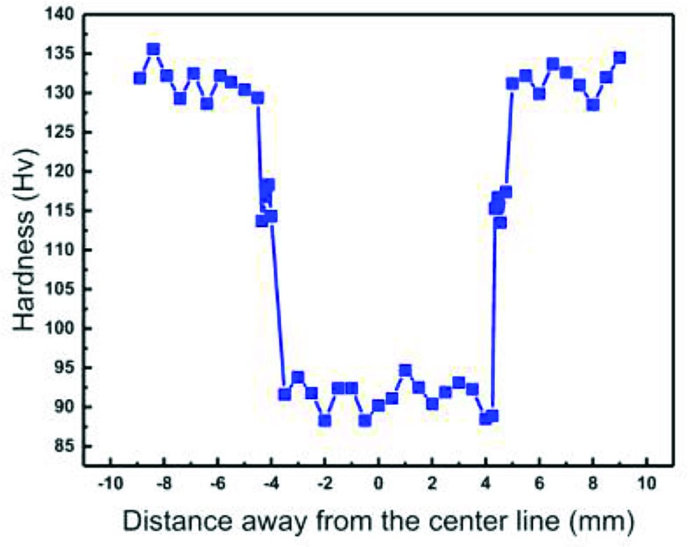
Hardness profile of the FZ and the HAZ of the DWMW joint.

Global view of butt joint fractured.
Static tensile nominal stress-strain curves of the weld joints are also examined to correlate the microstructural behavior (Figure 10). The mean ultimate tensile strength and elongation were 302 MPa and 4.5 %, respectively.

Nominal stress-strain curves of the DWMW joints.
The fracture surface exhibits no obvious porosity, slag inclusion and other defects (Figure 11(a)). As shown in Figures 11(b) and 11(c), fracture was consisted of equiaxed dimples of different sizes. The larger dimple size was about 15 μm and the smaller was about 3 μm, showing a quasi-cleavage-like fracture characteristic.

Fracture morphologies of a DWMW joint after tensile testing: (a) general view; (b) the ductile fracture appearance and (c) details of the ductile fracture surface.
Discussion
Microstructural evolution
DWMW, at a high welding speed, experiences a rapid cooling process, so its solidification characteristics are a little different from that of the traditional MIG welding process.
Upon cooling, solidification of the FZ took place first at the partially melted or solid grains along the fusion boundary (i.e. at the solid-liquid interface), due to the cooling effect of the groove, the existence of large thermal gradient between the interface of BM and the molten pool, and small growth rate. In the subsequent solidification process, grains in the fine equiaxed crystal zone rapidly grew along to the preferred crystallographic directions. The proceeding would have the maximum growth speed toward the fusion center and subsequently grow into the columnar crystal structure (Figure 6(d)). This transition found near the FZ with coarser columnar grains had an abrupt change of grain size (Figure 6(d)), which maybe lead to a large gradient of mechanical properties.
The equiaxed dendritic grains in the WZ were formed (Figure 6(b)) due to the existence of dissociate dendrite arms and the mild cooling in the pool. The weld center was dominated by the heat sources and the strong arc stirring effect on weld pool. Because the T-arc had an additional stirring effect on the pool, it could break up the coarsened dendrite structure and offered lots of nucleation sites. This structure would benefit the mechanical properties of the DWMW bead.
The wide of the HAZ was a direct function of the heat input and thermal conductivity of the BM (Figure 6(c)). A larger grain size was attributed to the recrystallization effect and was very critical in the welding of aluminum alloys, especially which were hardened by precipitation.
Welding efficiency analysis
At present, due to competitive industrial market, the welding efficiency has become a matter of great concern [29, 30, 31, 32, 33, 34, 35, 36, 37, 38, 39, 40, 41, 42, 43, 44, 45, 46, 47, 48], and the welding speed is one of the important factors to represent the welding efficiency.
Figure 12 shows the welding speeds of different fusion welding methods for 1–7 mm aluminum alloy plates [1, 5, 8, 13, 29–46]. As presented above, the welding speeds of MIG and tungsten inert gas (TIG) welding, below 1000 mm/min, were lower than that of other welding methods. Nevertheless, the above two welding methods have many advantages such as simple operation, cheap equipment and cost reduction [7, 11]. In addition, laser welding and hybrid laser-arc welding could achieve a higher range of welding speeds from 1000 to 6000 mm/min. On the one hand, due to their high-energy density, they have a higher welding efficiency than that of arc welding. On the other hand, the equipment and welding costs are far higher, and they are susceptible to the occurrence of welding defects [8].
![Figure 12: Comparison of welding speeds for aluminum alloys of varying thicknesses using different fusion welding methods [1, 5, 8, 13, 29–46].](/document/doi/10.1515/htmp-2018-0073/asset/graphic/j_htmp-2018-0073_fig_012.jpg)
Comparison of welding speeds for aluminum alloys of varying thicknesses using different fusion welding methods [1, 5, 8, 13, 29–46].
The red marks represent the welding speed interval produced by DWMW in this study. Compared to the traditional single-wire MIG welding, because two wires simultaneously provided heat energy to the BM, DWMW could change the heat distribution, effectively avoid undercut, yield welding seams with high quality, and improve the welding speed (1100–1200 mm/min) [26, 49]. In addition, in contrast to the traditional MIG and laser-arc welding [7, 50, 51] which had a tensile strength between 260 and 341 MPa,DWMW improved the welding efficiency without reducing the mechanical properties of the joints, thereby having a wide application prospect in the field of aluminum alloy welding.
Conclusions
In summary, 4 mm thick A7N01-T4 aluminum alloy plates were welded by DWMW at a high welding speed of 1200 mm/min. For the DWMW joint of A7N01 aluminum alloy, the WZ showed a dendritic structure of equiaxed grains, and in the FZ, the microstructure existed as a fine equiaxed crystal structure about 100 µm in thickness. In the WZ adjacent to the FZ, elongated columnar crystal structure distributed along to the interface, and coarse microstructure in the HAZ were found showing a typical rolling texture. The main precipitates in the WZ were assumed to be Fe-enriched phases, and Mg- and Zn-enriched phases. Tensile fracture generally occurred in the WZ adjacent to the FZ with a decrease in ductility, and it was consistent with the results of the microstructure analysis and hardness profile. The mean ultimate tensile strength and elongation of specimens are 302 MPa and 4.5 %, respectively. DWMW improved the welding efficiency without reducing the mechanical properties of the joints, thereby having a good application prospect.
Funding statement: This study was supported by the National Natural Science Foundation of China under Grant No. 51601121, and Liaoning Province Science Foundation Program No. L201624 and 201602570.
References
[1] L. Zhang, X.Y. Li, Z.R. Nie, H. Huang, J.T. Sun and J. Mater, Eng. Perform. , 25 (2016) 1870–1879.10.1007/s11665-016-2014-7Search in Google Scholar
[2] Q.J. Meng and G.S. Frankel, J. Electrochem. Soc., 151 (2004) B271–B283.10.1149/1.1695385Search in Google Scholar
[3] S.S. Sharma, K. Jagannath and P.R. Prabhu, Int. J. Remote Sens., 29 (2013) 7003–7028.Search in Google Scholar
[4] T.E. Borchers, D.P. Mcallister and W. Zhang, Metall. Mater. Trans. A, 46 (2015) 1827–1833.10.1007/s11661-015-2796-5Search in Google Scholar
[5] Q.Y. Wang, H. Chen, P.X. Qiu and Z.T. Zhu, Metall. Mater. Trans. B, 48 (2017) 1–11.10.1007/s11663-016-0782-ySearch in Google Scholar
[6] S.D. Ji, X.C. Meng, J.W. Xing, L. Ma and S.S. Gao, High Temp. Mater. Proc., 35 (2016) 843–851.10.1515/htmp-2015-0063Search in Google Scholar
[7] Z.C. Dai, X.W. Zhao, Z.H. Yun, J.J. Wu and Q.S. Li, Hot Work Technol., 44 (2015) 214–216.Search in Google Scholar
[8] S. Katayama, A. Matsunawa and K. Kojima, Weld. Int., 12 (1998) 774–789.10.1080/09507119809448977Search in Google Scholar
[9] H. Zhao, D.R. White and T. DebRoy, Metallurgical Rev. , 44 (1999) 238–266.10.1179/095066099101528298Search in Google Scholar
[10] J.N. Qiao, J.X. Lu and S.K. Wu, Int. J. Fatigue , 98 (2017) 32–40.10.1016/j.ijfatigue.2017.01.008Search in Google Scholar
[11] N. Xia, W.T. Jin, D.U. Gang, C.H. Zhou, G.E. Huai-Pu and G.Q. Gou, Electr. Weld. Mach., 44 (2014) 74–77.Search in Google Scholar
[12] C. Liu, D.O. Northwood and S.D. Bhole, Mater. Des. , 25 (2004) 573–577.10.1016/j.matdes.2004.02.017Search in Google Scholar
[13] O.T. Ola and F.E. Doern, Mater. Des. , 77 (2015) 50–58.10.1016/j.matdes.2015.03.064Search in Google Scholar
[14] S.L. Yang, B. Luo, R.Y. Lv, L.C. Meng and Q.L. Lin, Adv. Mater. Res., 430-432 (2012) 2091–2094.10.4028/www.scientific.net/AMR.430-432.2091Search in Google Scholar
[15] N.B. Potluri, P.K. Ghosh, P.C. Gupta and Y.S. Reddy, Weld. J., 75 (1996) 660–666.Search in Google Scholar
[16] S.D. Ji, Z.W. Li, Y. Wang, L. Ma and L.G. Zhang, High Temp. Mater. Proc., 36 (2016) 693–699.10.1515/htmp-2016-0012Search in Google Scholar
[17] A.G. Paleocrassas and J.F. Tu, Feasibility investigation of laser welding aluminum alloy 7075-T6 through the use of a 300 W, single-mode, ytterbium fiber optic laser, North Carolina State University, America (2005).10.2351/1.5060497Search in Google Scholar
[18] S. Katayama and K. Ogawa, Weld. Int., 27 (2013) 172–183.10.1080/09507116.2011.600016Search in Google Scholar
[19] B. Hu and I.M. Richardson, Weld. World, 50 (2013) 51–57.10.1007/BF03266536Search in Google Scholar
[20] G. Campana, A. Ascari, A. Fortunato and G. Tani, Appl. Surf. Sci., 255 (2009) 5588–5590.10.1016/j.apsusc.2008.07.169Search in Google Scholar
[21] S. Liu, J. Li, G. Mi, C. Wang and X. Hu, Int. J. Adv. Manuf. Technol., 87 (2016) 1–10.10.1007/s00170-016-8525-4Search in Google Scholar
[22] X.L. He, C. Cao, P. Qiu and Y. Cui, Electr. Weld. Mach., 45 (2015) 32–35.Search in Google Scholar
[23] D.J. Ye, X.M. Hua, C. Xu, F. Li and Y.X. Wu, Int. J. Adv. Manuf. Technol., 89 (1–4) (2016) 1–10.10.14257/ijast.2016.89.01Search in Google Scholar
[24] J. Zhu, Y. Wang, D. Chen, Z. Ming, B. Tan and H. Liu, Ordnance Mater. Sci. Eng. , 32 (2009) 39–42.Search in Google Scholar
[25] H. Miyazaki, H. Miyauchi, Y. Sugiyama and T. Shinoda, Weld. Int., 7 (1993) 431–437.10.1080/09507119309548422Search in Google Scholar
[26] P. Yao, J.X. Xue, K. Zhou, X.J. Wang and Q. Zhu, J. Mater. Process. Technol., 229 (2016) 111–120.10.1016/j.jmatprotec.2015.08.031Search in Google Scholar
[27] P. Yao, J.X. Xue and K. Zhou, Int. J. Adv. Manuf. Technol., 79 (2015) 2107–2116.10.1007/s00170-015-7039-9Search in Google Scholar
[28] P. Yao, J.X. Xue, K. Zhou and X.J. Wang, Math. Probl. Eng., 10 (2014) 1–8.Search in Google Scholar
[29] J. Shi, H.U. Ming-Hua, X.Q. Zhu and W.J. Chen, Electr. Weld. Mach., 44 (2014) 146–148.Search in Google Scholar
[30] Y.Q. Zhang, C.L. Yang, S.B. Lin and C.L. Fan, Trans. China Weld. Inst., 36 (2015) 53–56.Search in Google Scholar
[31] D.X. Yang, X.Y. Li, Z.R. Nie, D.Y. He, H. Huang and G.Z. Zhang, Rare Metal Mater. Eng., 41 (2012) 1713–1716.10.1016/S1875-5372(13)60011-9Search in Google Scholar
[32] K. Yan, Z.Q. Shi and X.L. Wang, Trans. China Weld. Inst., 33 (2012) 33–36.Search in Google Scholar
[33] P.M.G.P. Moreira, M.A.V.D. Figueiredo and P.M.S.T.D. Castro, Theor. Appl. Fract. Mec., 48 (2007) 169–177.10.1016/j.tafmec.2007.06.001Search in Google Scholar
[34] Y.P. Kim, N. Alam, H.S. Bang and H.S. Bang, Sci. Technol. Weld. Joining, 11 (2006) 295–307.10.1179/174329306X107674Search in Google Scholar
[35] Z.D. Zhang and X.Y. Kong, Adv. Mater. Res., 295-297 (2011) 1933–1937.10.4028/www.scientific.net/AMR.295-297.1933Search in Google Scholar
[36] P. Kah, M. Olabode, E. Hiltunen and J. Martikainen, Mechanika, 19 (2013) 96–103.10.5755/j01.mech.19.1.3618Search in Google Scholar
[37] N. Xia, W.T. Jin, G. Du, C.H. Zhou and H.P. Ge, Electr. Weld. Mach., 44 (2014) 74–77.Search in Google Scholar
[38] H.H. Yan, K.F. Zhang and Y. Wu, Trans. China Weld. Inst., 32 (2011) 97–100.Search in Google Scholar
[39] L. Cretteur and S. Marya, Weld. Int., 14 (2000) 120–134.10.1080/09507110009549150Search in Google Scholar
[40] R. Akhter, L. Ivanchev and H.P. Burger, Mater. Sci. Eng. A, 447 (2007) 192–196.10.1016/j.msea.2006.10.148Search in Google Scholar
[41] A. Ancona, P.M. Lugarà, D. Sorgente and L. Tricarico, J. Mater. Process. Technol., 191 (2007) 381–384.10.1016/j.jmatprotec.2007.03.048Search in Google Scholar
[42] R. Braun, Mater. Sci. Eng. A, 426 (2006) 250–262.10.1016/j.msea.2006.04.033Search in Google Scholar
[43] D.Q. Zhang, X. Jin, L.X. Gao, H.G. Joo and K.Y. Lee, Mater. Sci. Eng. A, 528 (2011) 2748–2754.10.1016/j.msea.2010.12.021Search in Google Scholar
[44] B. Hu and I.M. Richardson, Mater. Sci. Eng. A, 459 (2007) 94–100.10.1016/j.msea.2006.12.094Search in Google Scholar
[45] J.N. Qiao, Q.M. Wang, J.L. Zou and S.K. Wu, China J. Lasers, 43 (2016) 62–69.Search in Google Scholar
[46] S.C. Wu, X.B. Xu, W.H. Zhang, Z. Li and D.R. Xu, Trans. China Weld. Inst., 33 (2012) 45–48.Search in Google Scholar
[47] S.D. Ji, Y. Wang, Z.W. Li, L. Ma, L.G. Zhang, Y.M. Yue and H. Temp, Mater. Proc., 36 (2017) 693–699.10.1515/htmp-2016-0012Search in Google Scholar
[48] K. Laha, K.S. Chandravathi, K.B.S. Rao, S.L. Mannan and D.H. Sastry, High Temp. Mater. Proc., 19 (2000) 141–150.10.1515/HTMP.2000.19.2.141Search in Google Scholar
[49] K. Li and Y.M. Zhang, IEEE Trans. Autom. Sci. Eng., 7 (2010) 826–839.10.1109/TASE.2009.2032156Search in Google Scholar
[50] X.Y. Yang, H. Chen, Q.Y. Wang and Z.T. Zhu, Trans. China Weld. Inst., 37 (2016) 114–118.Search in Google Scholar
[51] G.X. Chen, Study on mechanical properties and stress corrosion behavior of A7N1S-T5 aluminum alloy MIG welded joints,Qingdao University of Science & Technology, Master Dissertation, (2015).Search in Google Scholar
© 2019 Walter de Gruyter GmbH, Berlin/Boston
This work is licensed under the Creative Commons Attribution 4.0 Public License.
Articles in the same Issue
- Frontmatter
- Review Article
- Research on the Influence of Furnace Structure on Copper Cooling Stave Life
- Influence of High Temperature Oxidation on Hydrogen Absorption and Degradation of Zircaloy-2 and Zr 700 Alloys
- Correlation between Travel Speed, Microstructure, Mechanical Properties and Wear Characteristics of Ni-Based Hardfaced Deposits over 316LN Austenitic Stainless Steel
- Factors Influencing Gas Generation Behaviours of Lump Coal Used in COREX Gasifier
- Experiment Research on Pulverized Coal Combustion in the Tuyere of Oxygen Blast Furnace
- Phosphate Capacities of CaO–FeO–SiO2–Al2O3/Na2O/TiO2 Slags
- Microstructure and Interface Bonding Strength of WC-10Ni/NiCrBSi Composite Coating by Vacuum Brazing
- Refill Friction Stir Spot Welding of Dissimilar 6061/7075 Aluminum Alloy
- Solvothermal Synthesis and Magnetic Properties of Monodisperse Ni0.5Zn0.5Fe2O4 Hollow Nanospheres
- On the Capability of Logarithmic-Power Model for Prediction of Hot Deformation Behavior of Alloy 800H at High Strain Rates
- 3D Heat Conductivity Model of Mold Based on Node Temperature Inheritance
- 3D Microstructure and Micromechanical Properties of Minerals in Vanadium-Titanium Sinter
- Effect of Martensite Structure and Carbide Precipitates on Mechanical Properties of Cr-Mo Alloy Steel with Different Cooling Rate
- The Interaction between Erosion Particle and Gas Stream in High Temperature Gas Burner Rig for Thermal Barrier Coatings
- Permittivity Study of a CuCl Residue at 13–450 °C and Elucidation of the Microwave Intensification Mechanism for Its Dechlorination
- Study on Carbothermal Reduction of Titania in Molten Iron
- The Sequence of the Phase Growth during Diffusion in Ti-Based Systems
- Growth Kinetics of CoB–Co2B Layers Using the Powder-Pack Boriding Process Assisted by a Direct Current Field
- High-Temperature Flow Behaviour and Constitutive Equations for a TC17 Titanium Alloy
- Research on Three-Roll Screw Rolling Process for Ti6Al4V Titanium Alloy Bar
- Continuous Cooling Transformation of Undeformed and Deformed High Strength Crack-Arrest Steel Plates for Large Container Ships
- Formation Mechanism and Influence Factors of the Sticker between Solidified Shell and Mold in Continuous Casting of Steel
- Casting Defects in Transition Layer of Cu/Al Composite Castings Prepared Using Pouring Aluminum Method and Their Formation Mechanism
- Effect of Current on Segregation and Inclusions Characteristics of Dual Alloy Ingot Processed by Electroslag Remelting
- Investigation of Growth Kinetics of Fe2B Layers on AISI 1518 Steel by the Integral Method
- Microstructural Evolution and Phase Transformation on the X-Y Surface of Inconel 718 Ni-Based Alloys Fabricated by Selective Laser Melting under Different Heat Treatment
- Characterization of Mn-Doped Co3O4 Thin Films Prepared by Sol Gel-Based Dip-Coating Process
- Deposition Characteristics of Multitrack Overlayby Plasma Transferred Arc Welding on SS316Lwith Co-Cr Based Alloy – Influence ofProcess Parameters
- Elastic Moduli and Elastic Constants of Alloy AuCuSi With FCC Structure Under Pressure
- Effect of Cl on Softening and Melting Behaviors of BF Burden
- Effect of MgO Injection on Smelting in a Blast Furnace
- Structural Characteristics and Hydration Kinetics of Oxidized Steel Slag in a CaO-FeO-SiO2-MgO System
- Optimization of Microwave-Assisted Oxidation Roasting of Oxide–Sulphide Zinc Ore with Addition of Manganese Dioxide Using Response Surface Methodology
- Hydraulic Study of Bubble Migration in Liquid Titanium Alloy Melt during Vertical Centrifugal Casting Process
- Investigation on Double Wire Metal Inert Gas Welding of A7N01-T4 Aluminum Alloy in High-Speed Welding
- Oxidation Behaviour of Welded ASTM-SA210 GrA1 Boiler Tube Steels under Cyclic Conditions at 900°C in Air
- Study on the Evolution of Damage Degradation at Different Temperatures and Strain Rates for Ti-6Al-4V Alloy
- Pack-Boriding of Pure Iron with Powder Mixtures Containing ZrB2
- Evolution of Interfacial Features of MnO-SiO2 Type Inclusions/Steel Matrix during Isothermal Heating at Low Temperatures
- Effect of MgO/Al2O3 Ratio on Viscosity of Blast Furnace Primary Slag
- The Microstructure and Property of the Heat Affected zone in C-Mn Steel Treated by Rare Earth
- Microwave-Assisted Molten-Salt Facile Synthesis of Chromium Carbide (Cr3C2) Coatings on the Diamond Particles
- Effects of B on the Hot Ductility of Fe-36Ni Invar Alloy
- Impurity Distribution after Solidification of Hypereutectic Al-Si Melts and Eutectic Al-Si Melt
- Induced Electro-Deposition of High Melting-Point Phases on MgO–C Refractory in CaO–Al2O3–SiO2 – (MgO) Slag at 1773 K
- Microstructure and Mechanical Properties of 14Cr-ODS Steels with Zr Addition
- A Review of Boron-Rich Silicon Borides Basedon Thermodynamic Stability and Transport Properties of High-Temperature Thermoelectric Materials
- Siliceous Manganese Ore from Eastern India:A Potential Resource for Ferrosilicon-Manganese Production
- A Strain-Compensated Constitutive Model for Describing the Hot Compressive Deformation Behaviors of an Aged Inconel 718 Superalloy
- Surface Alloys of 0.45 C Carbon Steel Produced by High Current Pulsed Electron Beam
- Deformation Behavior and Processing Map during Isothermal Hot Compression of 49MnVS3 Non-Quenched and Tempered Steel
- A Constitutive Equation for Predicting Elevated Temperature Flow Behavior of BFe10-1-2 Cupronickel Alloy through Double Multiple Nonlinear Regression
- Oxidation Behavior of Ferritic Steel T22 Exposed to Supercritical Water
- A Multi Scale Strategy for Simulation of Microstructural Evolutions in Friction Stir Welding of Duplex Titanium Alloy
- Partition Behavior of Alloying Elements in Nickel-Based Alloys and Their Activity Interaction Parameters and Infinite Dilution Activity Coefficients
- Influence of Heating on Tensile Physical-Mechanical Properties of Granite
- Comparison of Al-Zn-Mg Alloy P-MIG Welded Joints Filled with Different Wires
- Microstructure and Mechanical Properties of Thick Plate Friction Stir Welds for 6082-T6 Aluminum Alloy
- Research Article
- Kinetics of oxide scale growth on a (Ti, Mo)5Si3 based oxidation resistant Mo-Ti-Si alloy at 900-1300∘C
- Calorimetric study on Bi-Cu-Sn alloys
- Mineralogical Phase of Slag and Its Effect on Dephosphorization during Converter Steelmaking Using Slag-Remaining Technology
- Controllability of joint integrity and mechanical properties of friction stir welded 6061-T6 aluminum and AZ31B magnesium alloys based on stationary shoulder
- Cellular Automaton Modeling of Phase Transformation of U-Nb Alloys during Solidification and Consequent Cooling Process
- The effect of MgTiO3Adding on Inclusion Characteristics
- Cutting performance of a functionally graded cemented carbide tool prepared by microwave heating and nitriding sintering
- Creep behaviour and life assessment of a cast nickel – base superalloy MAR – M247
- Failure mechanism and acoustic emission signal characteristics of coatings under the condition of impact indentation
- Reducing Surface Cracks and Improving Cleanliness of H-Beam Blanks in Continuous Casting — Improving continuous casting of H-beam blanks
- Rhodium influence on the microstructure and oxidation behaviour of aluminide coatings deposited on pure nickel and nickel based superalloy
- The effect of Nb content on precipitates, microstructure and texture of grain oriented silicon steel
- Effect of Arc Power on the Wear and High-temperature Oxidation Resistances of Plasma-Sprayed Fe-based Amorphous Coatings
- Short Communication
- Novel Combined Feeding Approach to Produce Quality Al6061 Composites for Heat Sinks
- Research Article
- Micromorphology change and microstructure of Cu-P based amorphous filler during heating process
- Controlling residual stress and distortion of friction stir welding joint by external stationary shoulder
- Research on the ingot shrinkage in the electroslag remelting withdrawal process for 9Cr3Mo roller
- Production of Mo2NiB2 Based Hard Alloys by Self-Propagating High-Temperature Synthesis
- The Morphology Analysis of Plasma-Sprayed Cast Iron Splats at Different Substrate Temperatures via Fractal Dimension and Circularity Methods
- A Comparative Study on Johnson–Cook, Modified Johnson–Cook, Modified Zerilli–Armstrong and Arrhenius-Type Constitutive Models to Predict Hot Deformation Behavior of TA2
- Dynamic absorption efficiency of paracetamol powder in microwave drying
- Preparation and Properties of Blast Furnace Slag Glass Ceramics Containing Cr2O3
- Influence of unburned pulverized coal on gasification reaction of coke in blast furnace
- Effect of PWHT Conditions on Toughness and Creep Rupture Strength in Modified 9Cr-1Mo Steel Welds
- Role of B2O3 on structure and shear-thinning property in CaO–SiO2–Na2O-based mold fluxes
- Effect of Acid Slag Treatment on the Inclusions in GCr15 Bearing Steel
- Recovery of Iron and Zinc from Blast Furnace Dust Using Iron-Bath Reduction
- Phase Analysis and Microstructural Investigations of Ce2Zr2O7 for High-Temperature Coatings on Ni-Base Superalloy Substrates
- Combustion Characteristics and Kinetics Study of Pulverized Coal and Semi-Coke
- Mechanical and Electrochemical Characterization of Supersolidus Sintered Austenitic Stainless Steel (316 L)
- Synthesis and characterization of Cu doped chromium oxide (Cr2O3) thin films
- Ladle Nozzle Clogging during casting of Silicon-Steel
- Thermodynamics and Industrial Trial on Increasing the Carbon Content at the BOF Endpoint to Produce Ultra-Low Carbon IF Steel by BOF-RH-CSP Process
- Research Article
- Effect of Boundary Conditions on Residual Stresses and Distortion in 316 Stainless Steel Butt Welded Plate
- Numerical Analysis on Effect of Additional Gas Injection on Characteristics around Raceway in Melter Gasifier
- Variation on thermal damage rate of granite specimen with thermal cycle treatment
- Effects of Fluoride and Sulphate Mineralizers on the Properties of Reconstructed Steel Slag
- Effect of Basicity on Precipitation of Spinel Crystals in a CaO-SiO2-MgO-Cr2O3-FeO System
- Review Article
- Exploitation of Mold Flux for the Ti-bearing Welding Wire Steel ER80-G
- Research Article
- Furnace heat prediction and control model and its application to large blast furnace
- Effects of Different Solid Solution Temperatures on Microstructure and Mechanical Properties of the AA7075 Alloy After T6 Heat Treatment
- Study of the Viscosity of a La2O3-SiO2-FeO Slag System
- Tensile Deformation and Work Hardening Behaviour of AISI 431 Martensitic Stainless Steel at Elevated Temperatures
- The Effectiveness of Reinforcement and Processing on Mechanical Properties, Wear Behavior and Damping Response of Aluminum Matrix Composites