Effect of Arc Power on the Wear and High-temperature Oxidation Resistances of Plasma-Sprayed Fe-based Amorphous Coatings
-
Jinheng Luo
 ,
Chaoping Jiang
,
Chaoping Jiang

Abstract
Atmospheric plasma spraying (APS) technique is employed to prepare Fe-based amorphous coatings on T91 steel substrate under various arc powers of 30 kW, 35 kW and 40kW. The morphology and microstructure of both Fe-based powders and amorphous coatings are characterized by X-ray diffraction (XRD) and scanning electron microscopy (SEM). In addition, the wear resistance and high-temperature oxidation resistance of the plasma-sprayed coatings at various arc powers are studied. It is found that with increasing the arc power, the content of the porosity and the amorphous phase in the coatings declines. Specifically, under 30 kW, 35 kW and 40 kW arc power, the porosity of the coatings is 7.96%, 6.13% and 5.75%. Correspondingly, the relative content of amorphous phase from the coatings is measured to be 96.07% (mass fraction), 73.89% and 65.54%. Moreover, under 40 kW arc power, it gives the coating the highest micro-hardness having more compact microstructure and more dispersive α-Fe grains. Besides, the coatings fabricated at high arc power exhibit less wear induced weight loss and less weight gain from high-temperature oxidation comparing with those fabricated at lower arc power.
1 Introduction
High temperature erosion is recognized as one of the main failure causes of utility boiler tubes. At present, an economical and effective way has been used to overcome this problem with the development of thermal sprayed protective coatings [1, 2, 3].
With high toughness and corrosion resistance [4, 5], the amorphous alloys are considered potential materials for multiple applications. Nevertheless, some limitations have been posed in the application of the amorphous alloys due to the challenges in the production of the amorphous structures [6]. High cooling rate is essential to form the amorphous structure from the liquid state. This leads to small thickness or cross sections in the resulting powders, ribbons or wires [7]. Consequently, the application of the amorphous alloys is hindered as structure materials. In addition, the higher cost also limits the application of the amorphous materials. Nevertheless, Fe-based amorphous alloys are generally known for their excellent hardness properties, superior corrosion and wear resistance, and relatively lower cost [8, 9, 10] among all amorphous alloys.
In order to proliferate the application of Fe-based amorphous alloys, thermal spraying technique is applied as potential fabrication technique for amorphous coatings considering the feature of rapid cooling [11, 12]. Recently, amorphous metallic coatings have been prepared by different spraying processes, such as high velocity oxygen fuel (HVOF) spraying [2, 13, 14] and plasma spraying (PS) [15, 16, 17]. In spite of the high cooling rate (~106 K/s) of the droplet, obtaining a complete amorphous coating is still difficult because of the uneven heating of the powder particles in plasma jet and the uneven oxidation of the depositing droplet. Kishitake et al. [18] fabricated Fe-based amorphous coating by APS process, and found there is a mixture of amorphous and crystalline phases in the coating with good wear and corrosion resistances. Zhao et al. [19] fabricated Mo-based amorphous and nanocrystalline alloy coatings by APS using the Mo-based amorphous powder
as the feedstock. It is found that the coating exhibited excellent wear resistance comparing with that of the substrate. Shi et al. [20] developed Fe-Si nano-particle composite coating (FSN) and Fe-Si micro-particle composite coating (FSM) via APS. The results show that the corrosion resistance of FSN was improved compared with that of FSM. Thus, it is reasonable to consider a hybrid coating with both amorphous and nano-crystalline structures to enhance corrosion rand wear resistances.
In the present study, Fe-based amorphous powder was used as the spraying feedstock, and atmospheric plasma spraying (APS) system was used to deposit the Fe-based alloy coatings. The microstructure, wear behavior, and high-temperature oxidation resistances of Fe-based amorphous coatings were investigated with samples deposited under different arc powers.
2 Experimental
2.1 Material
Fe-based alloy powders were employed as thermal spray material, which were prepared by high pressure argon gas atomization, then sieved and divided into different size ranges. The powders used in this experiment are spherical with a size range from 40 to 60 μm. The nominal composition of the feedstock powders were shown in Table 1.
Composition of the spraying powders (wt%)
| Component | Mo | Cr | Ni | P | Si | B | C | Fe |
|---|---|---|---|---|---|---|---|---|
| Content% | 4.1 | 8.3 | 3.63 | 8.34 | 3.41 | 1.52 | 4.84 | Bal. |
2.2 Spraying process
The rectangular T91 steel plates with the dimension of 15 mm × 15 mm × 5 mm were used as substrates. In order to obtain clean and rough surface for improving the bonding strength between the coating and substrate, the substrates were immersed in acetone to eliminate grease and other organic matter followed by drying at room temperature, and then grit-blasted for about 30 seconds with alumina particles before spraying.
In this paper, the Fe-based amorphous coatings were fabricated by an atmospheric plasma spraying system (GP-80, Taizhou, China) with variable power levels. The detailed spraying parameters for the APS process are presented in Table 2. During spraying process, in order to obtain an enhanced glass forming ability (GFA), the substrate should be cooled continuously by compressed airflow.
The parameters of APS for Fe-based amorphous coatings
| Parameters | Values | ||
|---|---|---|---|
| Spraying powers (kW) | 30 | 35 | 40 |
| Spraying distance (mm) | 110 | ||
| Powder feed rate (g/min) | 10 | ||
| Primary gaspressure (Ar), MPa | 0.8 | ||
| Auxiliary gas pressure (H2), | 0.4 | ||
| Primary gas flow (L/min) | 26 | ||
| Auxiliary gas flow (L/min) | 5 |
2.3 Characterization
Scanning electron microscopy (SEM) (S-4800, Hitachi, Japan) was used to understand the morphology and the cross section microstructure of as-deposited coatings. Furthermore, the worn surface of the specimens was also studied by SEM. The apparent porosity of coatings was quantitatively characterized using image analysis technique using at least three micrographs of coatings. The phase transformation during each process were investigated using X-ray diffraction (XRD) (D/max 2500PC, Rigaku, Japan) with Cu Kα radiation in a 2θ range between 15∘ and 85∘ at 10∘ min−1. Furthermore, the relative crystallinity of the Febased amorphous coatings was calculated by means of the XRD diffraction patterns.
2.4 Hardness and wear test
The micro-hardness on the cross section of the amorphous coatings were measured using an optical microscope (OM) equipped with Vickers under 1N load applied over a period of 15 s (XH-1000TM/LCD). The dry wear test was carried out using a ring on block type tester (M-2000). During the testing process, the surface of the amorphous coatings was contact well with the surface of the GCr15 high carbon steel ring. The mass loss of the coatings was measured by an electronic precision balance (BS400-WE, Sartorius AG, Germany) with the accuracy of 0.1mg.
2.5 High-temperature oxidation test
To examine the high-temperature oxidation resistance of the coatings, the as-sprayed coatings were oxidized at 700∘C for 84 h in air atmosphere. During the oxidation process, the mass gain of the coatings was measured by an electronic precision balance (BS400-WE, Sartorius AG, Germany) with the accuracy of 0.1 mg. The phase composition of the coatings was analyzed by X-ray diffraction (XRD) (D/max 2500PC, Rigaku, Japan) with Cu Kα radiation in a 2θ range between 20∘ and 80∘ at 10∘ min−1.
3 Results and discussion
3.1 Surface morphology and cross-sectional structure of the coatings
Figure 1 and Figure 2 show the surface morphology and cross-sectional structure of the amorphous coatings deposited under different arc powers. As shown in Figure 1a, the coating obtained with a low arc power of 30 kW presents many unmelted particles and pores on the surface. It has been revealed that the low arc power is not sufficient to completely melt the powder particles, resulting in a loose coating. When the arc power increased to 35 kW and 40 kW, the amount of unmelted particles reduced, together with the size and amount of the voids in the coating decreased (see Figure 1b and 1c). The results show that the 40 kW plasma arc power produces the most compact microstructure compared with the coatings obtained at lower arc powers of 30 kW and 35 kW.

SEM images of surface of the amorphous coatings deposited under different spraying power levels (a) 30kW, (b) 35kW and (c) 40kW, respectively.

SEM images of the cross section of the amorphous coatings deposited under different spraying power levels (a) 30kW, (b) 35kW and (c) 40kW, respectively.
The voids in a plasma-sprayed coating will seriously affect the overall performance of the coating [21]. From Figure 2, the coating exhibits a porous, layered structure with no microcracks observed. The Fe-based amorphous coating presents a typical lamellar structure with pores, intersplat cracks and unmelted or incompletely melted particles. The presence of unmelted and incompletely melted particles increases the porosity of the coating. Consequently, this weakens the bonding between the splats in the coating. The porosity of the coatings obtained at different arc powers is 7.96% (30 kW), 6.13% (35 kW), and 5.75% (40 kW) respectively. With large arc power, the temperature of the plasma arc increases, and sufficient heating of the powder particle is expected. As a result, good melting of the powders leads to sufficient spreading of the molten particles, which counters the formation of the pores during deposition [22]. The pores in the coating are generally considered as original sites of cracking when the internal stress exists.
3.2 XRD analysis of the coatings
Figure 3 shows the XRD patterns of the amorphous powder and the coatings prepared with three arc powers. There is a broad halo peak at about 44∘ with no crystallization peak in the XRD pattern of the powder, indicating the presence of amorphous phase. For the deposited amorphous coatings, the wide halo peaks indicate appearance of the amorphous phases, while the low intensity of diffraction peaks at about 44∘ indicates the formation of nanoscale α-Fe crystals in the coating. These demonstrate that the powder exhibits amorphous structure, while the coating is a partially amorphous with a small amount of α-Fe crystal phase [23]. Moreover, the intensity of α-Fe peak in the coating decreases with increasing arc power, which indicates that the high arc power could be favorable to the formation of α-Fe phase in the coating [24, 25]. Therefore the content of the amorphous phase decreases as the arc power increases. By calculations based on XRD patterns, the relative contents of the amorphous phase of the coatings prepared at 30 kW, 35 kW, and 40 kW were calculated as 96.07 wt%, 73.89 wt%, and 65.54 wt%, respectively. Therefore, with the increased plasma spraying power, the content of amorphous phase in the sprayed Fe-based amorphous coating decreases, which may be due to the transformation of partial amorphous phases into crystalline phase during plasma spraying [24]. As the coating power increases, the partial transformation of amorphous phase in the coating is closely related to the deposition characteristics of the molten particles. During spraying, the powder particles are heated and transferred to molten or semi-molten state. The molten or semi-molten particle spreads, solidifies on the substrate surface to finally form splats. It is well known that there is a high cooling rate of the molten particle in the solidification process, which effectively prevents the crystallization tendency of the molten particle and thus ensures a high degree of amorphization [26]. Considering the above analysis, the content of the amorphous phase largely depends on the cooling and oxidation of the molten particle, as well as the heat accumulation in the coating [27]. As the arc power increases, the temperature of the plasma arc elevates and preheats the substrate surface or deposited splat surface which slows the cooling rate of the molten particles. The oxidation of the particles also reduces the cooling rate of the molten particles due to the lower thermal conductivity of the metallic oxides. Moreover, the latent heat released during crystallization also hinders the cooling of the molten particles. As a result, the amorphization process is suppressed and the crystallization process is encouraged.
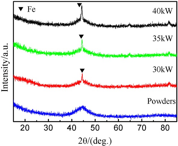
XRD patterns of the powders and coatings deposited under different spraying power levels.
3.3 Wear resistance of the coatings
Figure 4 shows the microhardness profiles along the cross-section of the coatings. It is found that the Fe-based amorphous coatings exhibit a higher hardness (650~770 HV) than the substrate (~250 HV). Furthermore, with the increase in plasma arc power, the microhardness value of the coating increases accordingly. The raw material powders were fully melted in the plasma jet with a higher power, which allows more sufficient spreading of the droplets. Consequently, the amount of pores is greatly reduced and the compactness of the splats in the coating is improved [28], which is in favor of the enhancement in the hardness of the coating.

Micro-hardness profiles of plasma-sprayed Fe-based amorphous coatings.
Figure 5 shows the weight loss of the coatings under dry friction conditions. With the increase of plasma arc power, the wear loss of amorphous coatings decreases. When the wear time is 80 minutes, the mass loss of the coating prepared at 40 kW is 6.6 mg, which is less than the wear loss of the coating prepared at 35 kW (7.8mg) and 30 kW (10.5 mg) for the same duration. As described by the Archard wear equation, the wear rate of the material is inversely proportional to its hardness [29]. Due to the higher microhardness [30], the coating prepared at higher arc power exhibits better wear resistance and its weight loss is less than that deposited at low power.

The wear losses of Fe-based amorphous coatings plasma-sprayed under different spraying power levels.
In order to understand the difference in wear mechanism of the coatings prepared under different arc powers, a further investigation on the wear surface was performed using SEM. As depicted in Figure 6, the main types of wear include wearing, delamination peeling and plough grooves. Layering and debris can be easily found in the coatings because of its layered structure and voids. The wear debris from the coating surface acts as the abrasive to produce more wear tracks on the surface of the coating, leading to an increased mass loss. For the coating deposited under 30 kW, partial surface of the substrate exposed after wear testing due to poor interlayer bonding and coating-substrate adhesion, as shown in Figure 6a. Moreover, the wear surface of the coating deposited under low plasma arc power is rougher than that deposited under high power, as indicated by severe wear of the coating surface.

Worn surface of Fe-based amorphous coatings deposited under different spraying power levels (a) 30kW, (b) 35kW and (c) 40kW, respectively.
3.4 High-temperature oxidation resistance of as-sprayed coatings
Figure 7 shows the varations in mass gains of the coatings oxidized at 700∘C for 84 h. It is clear that the curves of the mass gain versus oxidation time for all coatings present a parabolic shape. This indicates the oxidation of the coatings in air follows the parabolic diffusion rule. As shown in Figure 8, the composite oxide (Fe,Cr)2O3 produced in the oxidized coating prepared under arc power of 35 kW. The same phase is also found in the oxidized coatings prepared under arc powers of 30 kW and 40 kW.

The mass gains of Fe-based amorphous coatings after oxidation at 700 ∘C for 84 h.

XRD pattern of the oxidized coating prepared under arc power of 35 kW.
According to Wagner theory of oxidation [31], chrome (Cr) atom in the coatings possesses high diffusion coefficient due to its small atomic diameter. Moreover, at low temperature, both iron and chrome oxides form because of comparative diffusion coefficient of iron and chrome atoms in the metal. As the temperature is high, the diffusion coefficient of chrome atom become higher than that of iron atom, resulting in the formation of chrome oxides in bulk, which cover the matrix or already formed iron oxides surfaces and form a dense oxidation film. At the early stage of oxidation of the coatings, the fast oxidation can be observed from Figure 7, which corresponds to the formation of the dense Cr2O3 film. As the protective Cr2O3 film is formed, the oxygen cannot diffuse into the coating to make it oxidized because the Cr2O3 film acts as a barrier for the oxygen diffusion. As a result, in the subsequent oxidation time from 12 h to 84 h, an obvious reduction in the oxidation rate is observed. As the arc power increases from 30 kW to 40 kW, the mass gain exhibits a significant decrease. As aforementioned in section 3.1, the porosity of the coatings presents a decreased tendency from 7.96% to 5.75% with the increase of the arc power from 30 kW to 40 kW. Although the same surface area was used for measurement of oxidation mass gain, the real oxidation area was significantly with increase of the porosity because of more oxygen channels provided by increased pores. Therefore, a distinct decrease in mass gain of oxidized coatings could be found with increasing the arc power.
4 Conclusions
The Fe-based alloy coatings were prepared on T91 steel substrate by atmospheric plasma spraying under different spraying powers. The influences of plasma spraying power on microstructure, porosity, amorphous phase content as well as wear resistance of Fe-based amorphous coatings were investigated. It was demonstrated that with the increasing of plasma spraying powers, the porosity and the amorphous phase content of coatings declined. This is attributed to the particles with high temperature and velocity would generate sufficient deformation after the impact on the substrate, which results in compact microstructure and low porosity. The coating deposited at 40 kW power with amorphous and nano-scale α-Fe phase composite structure exhibited good wear resistance for the more compact structure and the higher micro-hardness. The wear of as-sprayed amorphous coatings under dry friction condition is dominated by abrasion, delamination and grooves mechanisms. Moreover, the oxidation mass gain of the coatings in air follows the parabolic diffusion rule because of the formation of dense oxide film and reduces with the increase of the arc power due to the decreased real oxidation area.
Acknowledgement
This work was supported by the National Key R&D Program of China with Project No. 2016YFC0801200, and the Special Fund for Basic Scientific Research of Central Colleges (No. 300102319304).
References
[1] M. Kaur, H. Singh and S. Prakash, Surf. Coat. Technol., 206 (2011) 530-541.10.1016/j.surfcoat.2011.07.077Search in Google Scholar
[2] G.J. Yang, C.J. Li and S.J. Zhang, J. Thermal Spray Technol., 17 (2008) 782-787.10.1007/s11666-008-9222-0Search in Google Scholar
[3] J.K.N. Murthy and B. Venkataraman, Surf. Coat. Technol., 200 (2006) 2642-2652.10.1016/j.surfcoat.2004.10.136Search in Google Scholar
[4] V. Venkatesh, Gouthama and K. Mondal, J. Alloys Compds., 692 (2016) 745-757.10.1016/j.jallcom.2016.09.033Search in Google Scholar
[5] Z.F. Yao, J.C. Qiao, J.M. Pelletier and Y. Yao, J. Alloys Compds., 690 (2017) 212-220.10.1016/j.jallcom.2016.08.178Search in Google Scholar
[6] S.H. Alavi, H.D. Vora, N.B. Dahotre and S.P. Harimlar, J. Mater. Process. Tech., 238 (2016) 55-64.10.1016/j.jmatprotec.2016.07.010Search in Google Scholar
[7] I.V. Sterkhova, V.I. Lad’Yanov, L.V. Kamaeva, N.V. Umnova and P.P. Umnov, Metall. Mater. Trans. A, 42 (2016) 1-9.Search in Google Scholar
[8] J. Dai, Y.G. Wang, L. Yang, G.T. Xia and Q.S. Zeng, Scripta Mater., 127 (2017) 88-91.10.1016/j.scriptamat.2016.09.006Search in Google Scholar
[9] Y.X. Zhuang,W.B.Wang, B.T. Han and P.F. Xing, J. Alloys Compds., 684 (2016) 649-655.10.1016/j.jallcom.2016.05.158Search in Google Scholar
[10] H. Li, Y. Lu, Z. Qin and X. Lu, Vacuum, 133 (2016) 105-107.10.1016/j.vacuum.2016.08.012Search in Google Scholar
[11] Z. Geng, S. Hou, G. Shi, D. Duan and S. Li, Tribol. Int., 104 (2016) 36-44.10.1016/j.triboint.2016.08.025Search in Google Scholar
[12] L. Baiamonte, F. Marra, S. Gazzola, P. Giovanetto and C. Bartuli, Surf. Coat. Technol., 295 (2015) 78-87.10.1016/j.surfcoat.2015.10.072Search in Google Scholar
[13] A. Milanti, V. Matikainen, G. Bolelli, H, Koivuluoto and L. Lusvarghi, J. Thermal Spray Technol., 25 (2016) 1-16.10.1007/s11666-015-0373-5Search in Google Scholar
[14] T. Peat, A.M. Galloway, A.I. Toumpis and D. Harvey, Surf. Coat. Technol., 299 (2016) 37-48.10.1016/j.surfcoat.2016.04.072Search in Google Scholar
[15] M.H. Foroushani, M. Shamanian, M. Salehi and F. Davar, Ceram. Int., 42 (2016) 15868-15875.10.1016/j.ceramint.2016.07.057Search in Google Scholar
[16] Q. Wei, J. Zhu and W. Chen, J. Thermal Spray Technol., 25 (2016) 605-612.10.1007/s11666-016-0378-8Search in Google Scholar
[17] B. Lv, X. Fan, H. Xie and T.J. Wang, J. Eur. Ceram. Soc., 37 (2017) 811-821.10.1016/j.jeurceramsoc.2016.08.033Search in Google Scholar
[18] K. Kishitake, H. Era and F. Otsubo, J. Thermal Spray Technol., 5 (1996) 283-288.10.1007/BF02645879Search in Google Scholar
[19] X.B. Zhao and Z.H. Ye, Surf. Coat. Technol., 228 (2013) S266-S270.10.1016/j.surfcoat.2012.05.127Search in Google Scholar
[20] X. Shi, X. Meng, Q. Zhong, J. Yang and M. Shu, J. Thermal Spray Technol., 25 (2016) 1079-1086.10.1007/s11666-016-0408-6Search in Google Scholar
[21] A. Kulkarni, S. Sampath, A. Goland, H. Herman and B. Dowd, Scripta Mater., 43 (2000) 471-476.10.1016/S1359-6462(00)00416-4Search in Google Scholar
[22] L. Lin, G.L. Li, H.D. Wang, J.J. Kang and Z.L. Xu, Appl. Surf. Sci., 356 (2015) 383-390.10.1016/j.apsusc.2015.08.019Search in Google Scholar
[23] R.Q. Guo, C. Zhang, Q. Chen, Y. Yang and N. Li, Corros. Sci., 53 (2011) 2351-2356.10.1016/j.corsci.2010.12.022Search in Google Scholar
[24] Y. An, G. Hou, J. Chen, X. Zhao and G. Liu, Vacuum, 107 (2014) 132-140.10.1016/j.vacuum.2014.04.021Search in Google Scholar
[25] G. Liu, Y. An, Z. Guo, J. Chen and G. Hou, Appl. Surf. Sci., 258 (2012) 5380-5386.10.1016/j.apsusc.2012.02.015Search in Google Scholar
[26] Y.Y. Zhou, G.Z. Ma, H.D. Wang, G.L. Li and S.Y. Chen, Mater. Des., 110 (2016) 332-339.10.1016/j.matdes.2016.08.003Search in Google Scholar
[27] Z. Zhou, L.Wang, D.Y. He, F.C.Wang and Y.B. Liu, J. Thermal Spray Technol., 20 (2011) 344-350.10.1007/s11666-010-9570-4Search in Google Scholar
[28] H. Zhang, Y. Hu, G. Hou, Y. An and G. Liu, J. Non-Cryst. Solids, 406 (2014) 37-44.10.1016/j.jnoncrysol.2014.09.041Search in Google Scholar
[29] B.D. Leonard, F. Sadeghi, S. Shinde and M. Mittelbach, Wear, 305 (2013) 312-321.10.1016/j.wear.2012.12.034Search in Google Scholar
[30] R.Q. Guo, C. Zhang, Y. Yang, Y. Peng and L. Liu, Intermetallics, 30 (2012) 94-99.10.1016/j.intermet.2012.03.026Search in Google Scholar
[31] K. Hauffe, Oxidation of metals, Plenum Press, New York, (1965).Search in Google Scholar
© 2019 J. Luo et al., published by De Gruyter
This work is licensed under the Creative Commons Attribution 4.0 Public License.
Articles in the same Issue
- Frontmatter
- Review Article
- Research on the Influence of Furnace Structure on Copper Cooling Stave Life
- Influence of High Temperature Oxidation on Hydrogen Absorption and Degradation of Zircaloy-2 and Zr 700 Alloys
- Correlation between Travel Speed, Microstructure, Mechanical Properties and Wear Characteristics of Ni-Based Hardfaced Deposits over 316LN Austenitic Stainless Steel
- Factors Influencing Gas Generation Behaviours of Lump Coal Used in COREX Gasifier
- Experiment Research on Pulverized Coal Combustion in the Tuyere of Oxygen Blast Furnace
- Phosphate Capacities of CaO–FeO–SiO2–Al2O3/Na2O/TiO2 Slags
- Microstructure and Interface Bonding Strength of WC-10Ni/NiCrBSi Composite Coating by Vacuum Brazing
- Refill Friction Stir Spot Welding of Dissimilar 6061/7075 Aluminum Alloy
- Solvothermal Synthesis and Magnetic Properties of Monodisperse Ni0.5Zn0.5Fe2O4 Hollow Nanospheres
- On the Capability of Logarithmic-Power Model for Prediction of Hot Deformation Behavior of Alloy 800H at High Strain Rates
- 3D Heat Conductivity Model of Mold Based on Node Temperature Inheritance
- 3D Microstructure and Micromechanical Properties of Minerals in Vanadium-Titanium Sinter
- Effect of Martensite Structure and Carbide Precipitates on Mechanical Properties of Cr-Mo Alloy Steel with Different Cooling Rate
- The Interaction between Erosion Particle and Gas Stream in High Temperature Gas Burner Rig for Thermal Barrier Coatings
- Permittivity Study of a CuCl Residue at 13–450 °C and Elucidation of the Microwave Intensification Mechanism for Its Dechlorination
- Study on Carbothermal Reduction of Titania in Molten Iron
- The Sequence of the Phase Growth during Diffusion in Ti-Based Systems
- Growth Kinetics of CoB–Co2B Layers Using the Powder-Pack Boriding Process Assisted by a Direct Current Field
- High-Temperature Flow Behaviour and Constitutive Equations for a TC17 Titanium Alloy
- Research on Three-Roll Screw Rolling Process for Ti6Al4V Titanium Alloy Bar
- Continuous Cooling Transformation of Undeformed and Deformed High Strength Crack-Arrest Steel Plates for Large Container Ships
- Formation Mechanism and Influence Factors of the Sticker between Solidified Shell and Mold in Continuous Casting of Steel
- Casting Defects in Transition Layer of Cu/Al Composite Castings Prepared Using Pouring Aluminum Method and Their Formation Mechanism
- Effect of Current on Segregation and Inclusions Characteristics of Dual Alloy Ingot Processed by Electroslag Remelting
- Investigation of Growth Kinetics of Fe2B Layers on AISI 1518 Steel by the Integral Method
- Microstructural Evolution and Phase Transformation on the X-Y Surface of Inconel 718 Ni-Based Alloys Fabricated by Selective Laser Melting under Different Heat Treatment
- Characterization of Mn-Doped Co3O4 Thin Films Prepared by Sol Gel-Based Dip-Coating Process
- Deposition Characteristics of Multitrack Overlayby Plasma Transferred Arc Welding on SS316Lwith Co-Cr Based Alloy – Influence ofProcess Parameters
- Elastic Moduli and Elastic Constants of Alloy AuCuSi With FCC Structure Under Pressure
- Effect of Cl on Softening and Melting Behaviors of BF Burden
- Effect of MgO Injection on Smelting in a Blast Furnace
- Structural Characteristics and Hydration Kinetics of Oxidized Steel Slag in a CaO-FeO-SiO2-MgO System
- Optimization of Microwave-Assisted Oxidation Roasting of Oxide–Sulphide Zinc Ore with Addition of Manganese Dioxide Using Response Surface Methodology
- Hydraulic Study of Bubble Migration in Liquid Titanium Alloy Melt during Vertical Centrifugal Casting Process
- Investigation on Double Wire Metal Inert Gas Welding of A7N01-T4 Aluminum Alloy in High-Speed Welding
- Oxidation Behaviour of Welded ASTM-SA210 GrA1 Boiler Tube Steels under Cyclic Conditions at 900°C in Air
- Study on the Evolution of Damage Degradation at Different Temperatures and Strain Rates for Ti-6Al-4V Alloy
- Pack-Boriding of Pure Iron with Powder Mixtures Containing ZrB2
- Evolution of Interfacial Features of MnO-SiO2 Type Inclusions/Steel Matrix during Isothermal Heating at Low Temperatures
- Effect of MgO/Al2O3 Ratio on Viscosity of Blast Furnace Primary Slag
- The Microstructure and Property of the Heat Affected zone in C-Mn Steel Treated by Rare Earth
- Microwave-Assisted Molten-Salt Facile Synthesis of Chromium Carbide (Cr3C2) Coatings on the Diamond Particles
- Effects of B on the Hot Ductility of Fe-36Ni Invar Alloy
- Impurity Distribution after Solidification of Hypereutectic Al-Si Melts and Eutectic Al-Si Melt
- Induced Electro-Deposition of High Melting-Point Phases on MgO–C Refractory in CaO–Al2O3–SiO2 – (MgO) Slag at 1773 K
- Microstructure and Mechanical Properties of 14Cr-ODS Steels with Zr Addition
- A Review of Boron-Rich Silicon Borides Basedon Thermodynamic Stability and Transport Properties of High-Temperature Thermoelectric Materials
- Siliceous Manganese Ore from Eastern India:A Potential Resource for Ferrosilicon-Manganese Production
- A Strain-Compensated Constitutive Model for Describing the Hot Compressive Deformation Behaviors of an Aged Inconel 718 Superalloy
- Surface Alloys of 0.45 C Carbon Steel Produced by High Current Pulsed Electron Beam
- Deformation Behavior and Processing Map during Isothermal Hot Compression of 49MnVS3 Non-Quenched and Tempered Steel
- A Constitutive Equation for Predicting Elevated Temperature Flow Behavior of BFe10-1-2 Cupronickel Alloy through Double Multiple Nonlinear Regression
- Oxidation Behavior of Ferritic Steel T22 Exposed to Supercritical Water
- A Multi Scale Strategy for Simulation of Microstructural Evolutions in Friction Stir Welding of Duplex Titanium Alloy
- Partition Behavior of Alloying Elements in Nickel-Based Alloys and Their Activity Interaction Parameters and Infinite Dilution Activity Coefficients
- Influence of Heating on Tensile Physical-Mechanical Properties of Granite
- Comparison of Al-Zn-Mg Alloy P-MIG Welded Joints Filled with Different Wires
- Microstructure and Mechanical Properties of Thick Plate Friction Stir Welds for 6082-T6 Aluminum Alloy
- Research Article
- Kinetics of oxide scale growth on a (Ti, Mo)5Si3 based oxidation resistant Mo-Ti-Si alloy at 900-1300∘C
- Calorimetric study on Bi-Cu-Sn alloys
- Mineralogical Phase of Slag and Its Effect on Dephosphorization during Converter Steelmaking Using Slag-Remaining Technology
- Controllability of joint integrity and mechanical properties of friction stir welded 6061-T6 aluminum and AZ31B magnesium alloys based on stationary shoulder
- Cellular Automaton Modeling of Phase Transformation of U-Nb Alloys during Solidification and Consequent Cooling Process
- The effect of MgTiO3Adding on Inclusion Characteristics
- Cutting performance of a functionally graded cemented carbide tool prepared by microwave heating and nitriding sintering
- Creep behaviour and life assessment of a cast nickel – base superalloy MAR – M247
- Failure mechanism and acoustic emission signal characteristics of coatings under the condition of impact indentation
- Reducing Surface Cracks and Improving Cleanliness of H-Beam Blanks in Continuous Casting — Improving continuous casting of H-beam blanks
- Rhodium influence on the microstructure and oxidation behaviour of aluminide coatings deposited on pure nickel and nickel based superalloy
- The effect of Nb content on precipitates, microstructure and texture of grain oriented silicon steel
- Effect of Arc Power on the Wear and High-temperature Oxidation Resistances of Plasma-Sprayed Fe-based Amorphous Coatings
- Short Communication
- Novel Combined Feeding Approach to Produce Quality Al6061 Composites for Heat Sinks
- Research Article
- Micromorphology change and microstructure of Cu-P based amorphous filler during heating process
- Controlling residual stress and distortion of friction stir welding joint by external stationary shoulder
- Research on the ingot shrinkage in the electroslag remelting withdrawal process for 9Cr3Mo roller
- Production of Mo2NiB2 Based Hard Alloys by Self-Propagating High-Temperature Synthesis
- The Morphology Analysis of Plasma-Sprayed Cast Iron Splats at Different Substrate Temperatures via Fractal Dimension and Circularity Methods
- A Comparative Study on Johnson–Cook, Modified Johnson–Cook, Modified Zerilli–Armstrong and Arrhenius-Type Constitutive Models to Predict Hot Deformation Behavior of TA2
- Dynamic absorption efficiency of paracetamol powder in microwave drying
- Preparation and Properties of Blast Furnace Slag Glass Ceramics Containing Cr2O3
- Influence of unburned pulverized coal on gasification reaction of coke in blast furnace
- Effect of PWHT Conditions on Toughness and Creep Rupture Strength in Modified 9Cr-1Mo Steel Welds
- Role of B2O3 on structure and shear-thinning property in CaO–SiO2–Na2O-based mold fluxes
- Effect of Acid Slag Treatment on the Inclusions in GCr15 Bearing Steel
- Recovery of Iron and Zinc from Blast Furnace Dust Using Iron-Bath Reduction
- Phase Analysis and Microstructural Investigations of Ce2Zr2O7 for High-Temperature Coatings on Ni-Base Superalloy Substrates
- Combustion Characteristics and Kinetics Study of Pulverized Coal and Semi-Coke
- Mechanical and Electrochemical Characterization of Supersolidus Sintered Austenitic Stainless Steel (316 L)
- Synthesis and characterization of Cu doped chromium oxide (Cr2O3) thin films
- Ladle Nozzle Clogging during casting of Silicon-Steel
- Thermodynamics and Industrial Trial on Increasing the Carbon Content at the BOF Endpoint to Produce Ultra-Low Carbon IF Steel by BOF-RH-CSP Process
- Research Article
- Effect of Boundary Conditions on Residual Stresses and Distortion in 316 Stainless Steel Butt Welded Plate
- Numerical Analysis on Effect of Additional Gas Injection on Characteristics around Raceway in Melter Gasifier
- Variation on thermal damage rate of granite specimen with thermal cycle treatment
- Effects of Fluoride and Sulphate Mineralizers on the Properties of Reconstructed Steel Slag
- Effect of Basicity on Precipitation of Spinel Crystals in a CaO-SiO2-MgO-Cr2O3-FeO System
- Review Article
- Exploitation of Mold Flux for the Ti-bearing Welding Wire Steel ER80-G
- Research Article
- Furnace heat prediction and control model and its application to large blast furnace
- Effects of Different Solid Solution Temperatures on Microstructure and Mechanical Properties of the AA7075 Alloy After T6 Heat Treatment
- Study of the Viscosity of a La2O3-SiO2-FeO Slag System
- Tensile Deformation and Work Hardening Behaviour of AISI 431 Martensitic Stainless Steel at Elevated Temperatures
- The Effectiveness of Reinforcement and Processing on Mechanical Properties, Wear Behavior and Damping Response of Aluminum Matrix Composites