Investigation on acoustic properties of metal hollow sphere A356 aluminum matrix composites
-
 ,
,

Abstract
The acoustic performance of metal hollow sphere (MHS) A356 aluminum matrix composites has a significant impact on their application, making it worthy of in-depth investigation. To investigate the acoustic performance and mechanism of MHS A356 aluminum matrix composites, in this study MHS A356 aluminum matrix composites with different structural parameters were fabricated using a casting method. The density of the MHS A356 aluminum matrix composites was measured using the direct measurement method, and the acoustic performance of the composites was measured using the impedance tube. The research results indicated that the average sound absorption coefficient of MHS A356 aluminum matrix composites increased with the decrease in sintering temperature and diameter of MHSs, and the increase in volume fraction of MHSs. When the sintering temperature of the MHS was at 1,100°C, with the volume fraction being 48.50% and the diameter being 1.88 mm, the average sound absorption coefficient of the MHS A356 aluminum matrix composites reached the optimal level, which was 0.23. Conversely, the sound transmission loss of MHS A356 aluminum matrix composites decreased with the increase in sintering temperature, volume fraction, and diameter of MHSs. When the sintering temperature of the MHS stood at 1,100°C, with the volume fraction being 40% and the diameter being 2.88 mm, the average sound transmission loss of the MHS A356 aluminum matrix composites attained the maximum value, which was 24.6 dB.
1 Introduction
Metal hollow sphere (MHS) composites are a type of metal porous material fabricated by casting or powder metallurgy techniques using MHSs and metal matrix materials [1,2]. Since the pore structure of MHS composites is introduced by MHSs, their structural and functional characteristics can be tailored according to specific requirements [3]. Compared with traditional metal foams, due to the strengthening effect of MHSs, the static and dynamic compression properties of MHS A356 aluminum matrix composites are much higher [4,5,6,7]. Furthermore, MHS A356 aluminum matrix composites have also been proven to have excellent thermal insulation [8], acoustic [9,10], nuclear shielding [11,12], and anti-explosion performance [13].
Thanks to their excellent acoustic performance, metal foam materials have been widely applied in noise control, architectural acoustics, industrial noise reduction, automotive industry, aerospace, and other fields [14,15,16,17,18,19]. MHS A356 aluminum matrix composites, as a type of porous material, have the characteristics of high porosity and low sound propagation velocity. Their highly configurable structure and material composition allow for adjusting their sound absorption, sound insulation, shock absorption, and noise reduction properties by modifying their microstructure and chemical composition, thereby demonstrating their enormous potential in these fields. The acoustic properties of metal porous materials can be influenced by a variety of factors, including porosity, pore size, material density, material thickness, surface properties of the material, and external factors [20,21]. To enhance the acoustic properties of metal porous materials, the following measures can be taken: increasing porosity, reducing pore size, decreasing material density, increasing material thickness, optimizing surface properties of the material, and controlling external factors [22,23]. These measures can enhance the absorption and reflection capabilities of metal porous materials toward sound waves, thereby improving their acoustic performance.
However, there are relatively few studies on the acoustic properties of MHS A356 aluminum matrix composites, especially the influence of structural parameters such as sintering temperature, diameter, and volume fraction of the MHSs on the acoustic properties of MHS A356 aluminum matrix composites. Meanwhile, the acoustic mechanism of MHS A356 aluminum matrix composites has not been clearly elaborated. These factors significantly limit the application of MHS A356 aluminum matrix composites in the field of acoustics. Therefore, studying the influence of structural parameters on the acoustic properties of MHS A356 aluminum matrix composites is of great significance for their acoustic applications. Meanwhile, clarifying the acoustic mechanism of MHS A356 aluminum matrix composites helps to understand the acoustic phenomena of MHS A356 aluminum matrix composites, which is also crucial for the design and application of MHS A356 aluminum matrix composites.
Therefore, in this study, MHS composites with different structural parameters were fabricated via a casting method using the 316L stainless steel hollow spheres and A356 aluminum alloy. Subsequently, the density of the MHS A356 aluminum matrix composites was characterized. Meanwhile, the acoustic properties of MHS A356 aluminum matrix composites were measured, and the effects of sintering temperature, volume fraction, and diameter of MHSs on the acoustic properties of MHS A356 aluminum matrix composites were investigated. Based on the experimental results, the acoustic mechanism of the MHS A356 aluminum matrix composites was analyzed.
2 Materials and methods
2.1 Materials
The MHSs utilized in this study were fabricated via the template and powder metallurgy method [24], and the MHSs sintered at various temperatures exhibited distinct wall porosities.
Table 1 presents the wall porosity of the MHSs after sintering at different temperatures. Table 2 outlines the three specifications of MHSs employed in the experiment. The A356 aluminum alloy, which boasted excellent casting performance, was selected as the matrix material.
Wall porosity of MHSs sintered at different temperatures
| No | 1 | 2 | 3 | 4 |
|---|---|---|---|---|
| Sintering temperature (°C) | 1,100 | 1,150 | 1,200 | 1,250 |
| Wall porosity (%) | 47.87 ± 0.05 | 38.10 ± 0.04 | 27.57 ± 0.07 | 24.44 ± 0.06 |
Wall thickness of MHSs with different diameters
| No | Diameter (mm) | Wall thickness (mm) |
|---|---|---|
| 1 | 1.55 ± 0.03 | 0.081 ± 0.003 |
| 2 | 2.88 ± 0.02 | 0.137 ± 0.003 |
| 3 | 5.76 ± 0.05 | 0.274 ± 0.005 |
2.2 Fabrication of the MHS A356 aluminum matrix composites
The MHS A356 aluminum matrix composites were fabricated by means of the process presented in Figure 1 [25]. Initially, the metal fiber grid and the MHSs were located in the forming cavity of the mold. Subsequently, the A356 alloy, the mold, and the crucible were assembled as demonstrated in Figure 1 and placed into the resistance furnace. Afterward, the resistance furnace was heated up to 710°C and maintained at that temperature for 45 min. Following that, a specific pressure was applied to the mold, which was gradually lowered along the crucible wall until it stopped moving. After being retained at 710°C for another 10 min, the mold and the crucible were removed from the resistance furnace and cooled down to room temperature by air. Eventually, the MHS A356 aluminum matrix composites were obtained.
![Figure 1
The flowchart of fabricating MHS A356 aluminum matrix composites [25].](/document/doi/10.1515/secm-2024-0036/asset/graphic/j_secm-2024-0036_fig_001.jpg)
The flowchart of fabricating MHS A356 aluminum matrix composites [25].
Figure 2 shows the sample graph prepared by the method presented in Figure 1.
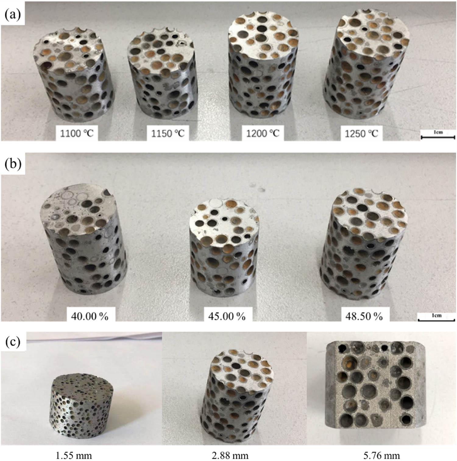
Sample diagram: (a) MHS A356 aluminum matrix composites with MHSs at different sintering temperatures, (b) MHS A356 aluminum matrix composites with different volume fractions of MHSs, and (c) MHS A356 aluminum matrix composites with different diameters of MHSs.
2.3 Characterization
2.3.1 Density of MHS A356 aluminum matrix composites
During the preparation of MHS A356 aluminum matrix composites, the true volume (VV1) of the MHS was calculated based on the volume (V) of the forming chamber in the mold and the volume fraction (V1) of the MHSs in the MHS A356 aluminum matrix composites. Then, based on the density (D) of the MHSs, the required mass (VV1D) was calculated.
After the preparation of MHS A356 aluminum matrix composites, the excess parts along both sides of the forming chamber were cut off using an electric spark wire cutting machine. Then, the mass, diameter, and height of the sample in the forming chamber section were measured. Finally, the density of the MHS A356 aluminum matrix composites was calculated based on the density formula.
2.3.2 Microstructure analysis of MHS A356 aluminum matrix composites
A section of 10 mm × 10 mm × 10 mm in size, including the wall of the MHS and the matrix, was cut off using an electric spark wire cutting machine. Then, the MHS A356 aluminum matrix composites were polished, and the microstructure was observed using a scanning electron microscope (SEM, SU-70).
2.3.3 Acoustic performance of the MHS A356 aluminum matrix composites
The SW477-type impedance tube was employed to measure the acoustic properties of MHS A356 aluminum matrix composites. When measuring the sound absorption coefficient of MHS A356 aluminum matrix composites, the BS EN ISO 10534-2:2001 and ASTM E1050-98 standards were adhered. Conversely, for measuring the sound transmission loss of MHS A356 aluminum matrix composites, the ASTM E2611-09 standard was followed.
During the acoustic performance test, MHS A356 aluminum matrix composites with dimensions of 20 mm × 30 mm were selected to measure their acoustic performance within the frequency range of 1,000–6,300 Hz. The acoustic performance curves of MHS A356 aluminum matrix composites were constructed using the average value obtained from testing five instances of MHS A356 aluminum matrix composites.
The measurement mechanism of the sound absorption coefficient of MHS A356 aluminum matrix composites is illustrated in Figure 3(a) [22]: First, two sound wave sensors were fitted in the direction where the sound wave came close to the test sample, in order to measure the sound pressure at two points, to acquire the sound transfer function at two sensors, and via further computation, to derive the sound wave reflected back by MHS A356 aluminum matrix composites, and to calculate the sound absorption coefficient of MHS A356 aluminum matrix composites through calculation. The measurement principle of the sound transfer loss of MHS A356 aluminum matrix composites is depicted in Figure 3(b) [23]: Two sound wave sensors were separately installed on the front and back sides of the test sample for measuring the sound pressure at these four points on both sides of the test sample, and the standing wave separation method was used to separately obtain the incident wave and the wave reflected by MHS A356 aluminum matrix composites, and then the sound wave received at the receiving end was separated to obtain the sound wave passing through the receiving end, and ultimately, after calculation, the transmission coefficient of the sound wave was obtained, and after logarithmic calculation, the transfer loss of the sound wave was achieved.
![Figure 3
Schematic diagram of impedance tube for measuring sound properties: (a) sound absorption coefficient [22] and (b) sound transmission loss [23].](/document/doi/10.1515/secm-2024-0036/asset/graphic/j_secm-2024-0036_fig_003.jpg)
Figure 4 shows the photo of the impedance tube.
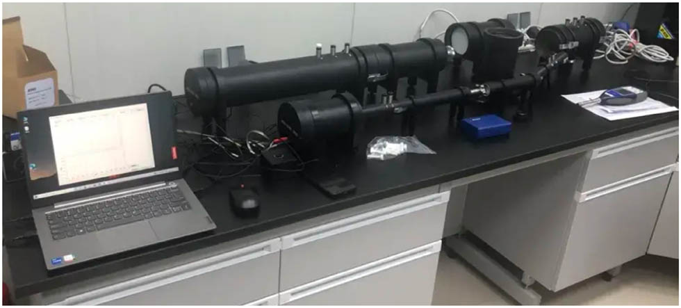
Photo of the impedance tube.
3 Results and analysis
3.1 Density of the MHS A356 aluminum matrix composites
The density of the MHS A356 aluminum matrix composites fabricated in the experiment was measured, and the results are presented in Table 3. From samples 1, 2, and 8 in Table 3, it can be seen that when the volume fraction of MHSs in MHS A356 aluminum matrix composites was 48.50%, the density of MHS A356 aluminum matrix composites fabricated by sintering MHSs with different diameters at the same temperature had a slight difference.
Density of the MHS A356 aluminum matrix composites
| Sample | Diameter (mm) | Sintering temperature of the MHSs (°C) | Volume fraction of the MHSs (%) | Density of MHS A356 aluminum matrix composites (g cm−3) |
|---|---|---|---|---|
| 1 | 1.55 | 1,100 | 48.50 | 1.74 ± 0.03 |
| 2 | 2.88 | 1,100 | 48.50 | 1.76 ± 0.06 |
| 3 | 2.88 | 1,150 | 48.50 | 1.84 ± 0.04 |
| 4 | 2.88 | 1,200 | 48.50 | 1.91 ± 0.02 |
| 5 | 2.88 | 1,250 | 48.50 | 1.99 ± 0.07 |
| 6 | 2.88 | 1,100 | 45.00 | 1.83 ± 0.04 |
| 7 | 2.88 | 1,100 | 40.00 | 1.91 ± 0.05 |
| 8 | 5.76 | 1,100 | 48.50 | 1.75 ± 0.03 |
From samples 2, 3, 4, and 5 in Table 3, the density of the MHS A356 aluminum matrix composites fabricated by MHSs with the same diameter increased gradually with increasing sintering temperature of MHSs, when the volume fraction of the MHSs was 48.50% in the MHS A356 aluminum matrix composites. From samples 2, 6, and 7 in Table 3, the density of the MHS A356 aluminum matrix composites increased with decreasing volume fraction of MHSs with the same diameter, when the sintering temperature of MHSs was 1,100°C.
3.2 Microstructural analysis
Figure 5 presents the observation result of the interface between the MHS and the matrix. As can be seen from Figure 5, a continuous transition layer is formed between the MHS and the matrix. From the distribution map of alloy elements, the alloying elements in the wall of the MHS diffuse into the matrix through the “original interface” between the MHS and the matrix, while the alloying elements in the matrix cannot diffuse into the MHS through the “original interface.”
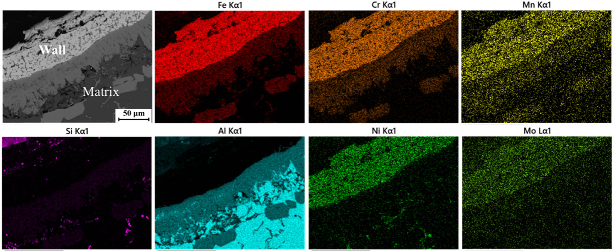
The distribution of alloying elements at the transition layer.
Based on the observations and the existing research results [2,3,4,5], it can be concluded that the transition layer phase is brittle and hard Fe2Al7Si-phase, the precipitated phases in the Al matrix are Si, Fe2Al4Si, and Al8Si6Mg3Fe.
3.3 Acoustic performance of the MHS A356 aluminum matrix composites
3.3.1 Sintering temperatures of the MHSs on the acoustic properties of MHS A356 aluminum matrix composites
Figure 6 shows the sound absorption coefficient and sound transmission loss of MHS A356 aluminum matrix composites fabricated using MHSs sintered at different temperatures, by testing samples 2, 3, 4, and 5 in Table 3. It can be seen from Figure 6 that the sound absorption coefficient and sound transmission loss of MHS A356 aluminum matrix composites gradually decreased with increasing sintering temperature of MHSs. However, the sound transmission loss of MHS A356 aluminum matrix composites showed only a slight difference.
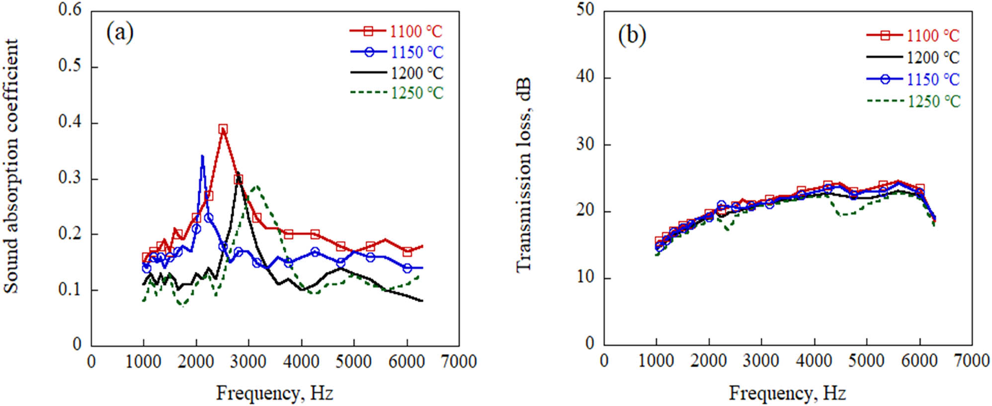
The acoustic properties of MHS A356 aluminum matrix composites fabricated by MHSs sintered at different sintering temperatures: (a) sound absorption coefficient and (b) sound transmission loss.
When the sintering temperature of MHSs was 1,100°C, the acoustic performance of MHS A356 aluminum matrix composites was the best, with an average sound absorption coefficient of 0.19, a sound absorption coefficient peak of 0.39, and an average sound transmission loss of 21.1 dB. When the sintering temperature of MHSs was 1,250°C, the acoustic performance of MHS A356 aluminum matrix composites was the worst, with an average sound absorption coefficient of 0.11, a sound absorption coefficient peak of 0.28, and an average sound transmission loss of 19.7 dB. Compared with MHS A356 aluminum matrix composites fabricated using MHSs sintered at 1,100°C, the average sound absorption coefficient of MHS A356 aluminum matrix composites decreased by 42.1%, the sound absorption coefficient peak decreased by 28.2%, and the average sound transmission loss decreased by 6.6%.
Based on Table 1, it can be seen that the wall porosity of the MHSs sintered at 1,100°C was the highest, the wall porosity of the MHSs sintered at 1,250°C was the lowest, and the volume fraction of MHSs in the MHS A356 aluminum matrix composites was 48.50%. Therefore, the different wall porosity of the MHSs was the reason for the different acoustic performance of the MHS A356 aluminum matrix composites. Additionally, the lower the sintering temperature of the MHSs, the better the acoustic performance of the MHS A356 aluminum matrix composites.
3.3.2 Diameter of the MHSs on the acoustic properties of MHS A356 aluminum matrix composites
Figure 7 presents the sound absorption coefficient and sound transmission loss of MHS A356 aluminum matrix composites fabricated using MHSs with different diameters, as determined by testing samples 1, 2, and 8 in Table 3. As can be seen from Figure 3(a), as the diameter of the MHSs decreased, the average sound absorption coefficient of the MHS A356 aluminum matrix composites gradually increased, while the sound absorption coefficient peak gradually decreased. Meanwhile, as shown in Figure 3(b), the sound transmission loss of the MHS A356 aluminum matrix composites gradually increased as the diameter of the MHSs decreased.
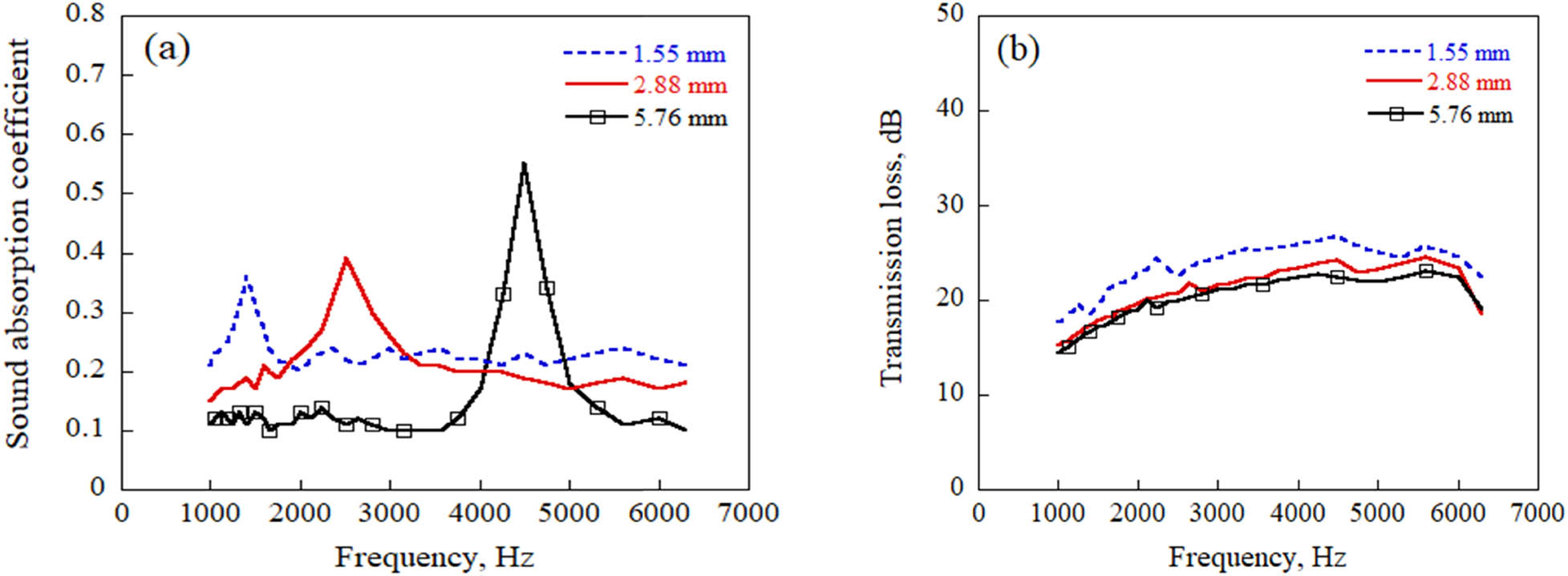
The acoustic properties of MHS A356 aluminum matrix composites fabricated by MHSs with different diameters: (a) sound absorption coefficient and (b) sound transmission loss.
When the MHS A356 aluminum matrix composites did not resonate with the sound waves, the average sound absorption coefficient of MHS A356 aluminum matrix composites fabricated using MHSs with a diameter of 5.76 mm was the lowest at 0.11, while the average sound absorption coefficient of MHS A356 aluminum matrix composites fabricated using MHSs with a diameter of 1.55 mm was the highest at 0.23. Compared to MHS A356 aluminum matrix composites fabricated using MHSs with a diameter of 5.76 mm, the average sound absorption coefficient of MHS A356 aluminum matrix composites increased by 109.1%.
When the MHS A356 aluminum matrix composites resonated with the sound wave, the sound absorption coefficient peak of MHS A356 aluminum matrix composites fabricated using MHSs with a diameter of 1.55 mm was the lowest at 0.36, while the sound absorption coefficient peak of MHS A356 aluminum matrix composites fabricated using MHSs with a diameter of 5.76 mm was the highest at 0.58. Compared with that of 1.55 mm, the sound absorption coefficient peak of MHS A356 aluminum matrix composites increased by 61.1%. Meanwhile, the average sound transmission loss of MHS A356 aluminum matrix composites fabricated using MHSs with a diameter of 1.55 mm was the highest at 23.5 dB, which was 15.2% higher than that of 5.76 mm (20.4 dB).
3.3.3 Volume fraction of the MHSs on the acoustic properties of MHS A356 aluminum matrix composites
Figure 8 presents the sound absorption coefficient and sound transmission loss of MHS A356 aluminum matrix composites fabricated using MHSs with different volume fractions, by testing samples 2, 6, and 7 in Table 3. As shown in Figure 8(a), it can be observed that as the volume fraction of the MHSs increased, the average sound absorption coefficient of the MHS A356 aluminum matrix composites gradually increased, while the sound absorption coefficient peak of the MHS A356 aluminum matrix composites gradually decreased. As presented in Figure 8(b), the sound transmission loss of the MHS A356 aluminum matrix composites gradually decreased as the volume fraction of the MHSs increased.
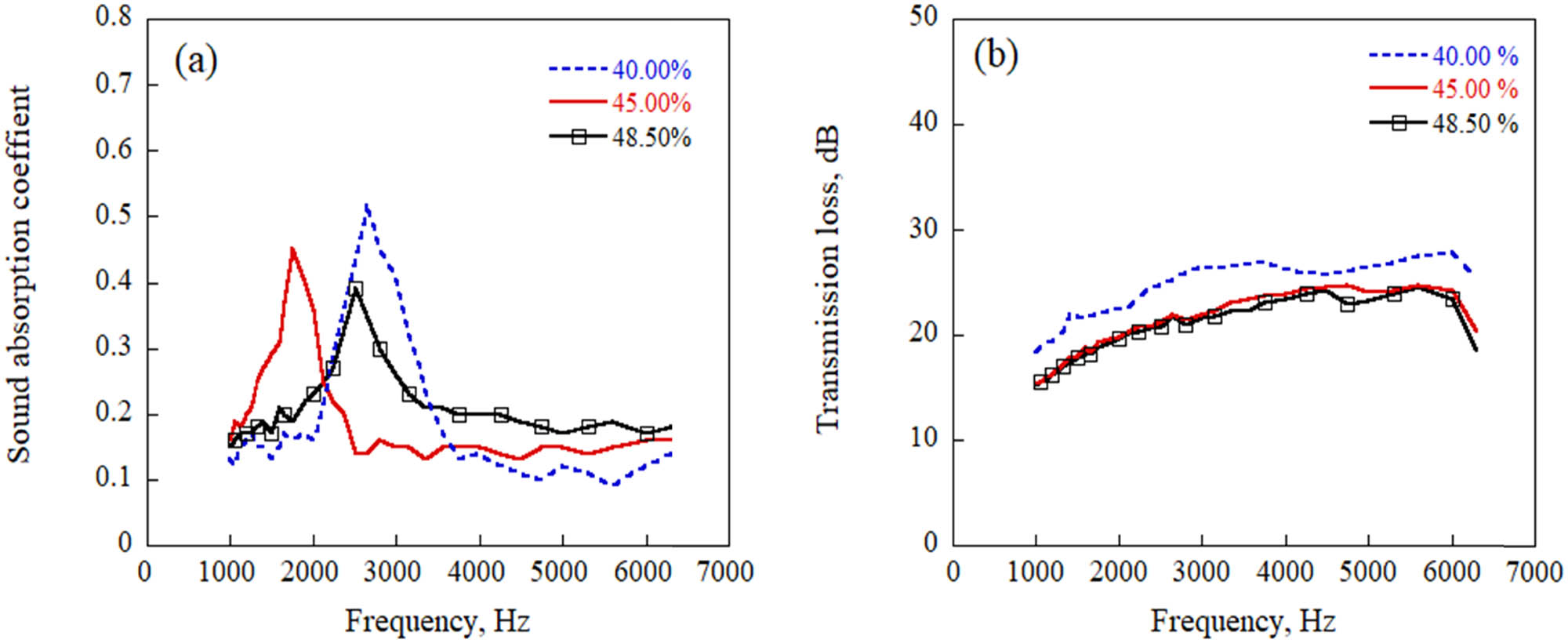
The acoustic properties of MHS A356 aluminum matrix composites with different volume fractions of the MHSs: (a) sound absorption coefficient and (b) sound transmission loss.
When the volume fraction of MHSs was 45.00 and 48.50%, the sound transmission loss of MHS A356 aluminum matrix composites was similar. However, the sound transmission loss of MHS A356 aluminum matrix composites with a 40.00% volume fraction of MHSs was significantly higher than that of MHS A356 aluminum matrix composites with 45.00 and 48.50% volume fractions of MHSs. When the volume fraction of MHSs was the highest (48.50%), the average sound absorption coefficient of MHS A356 aluminum matrix composites was the highest at 0.19, the sound absorption coefficient peak of MHS A356 aluminum matrix composites was the lowest at 0.39, and the average sound transmission loss of MHS A356 aluminum matrix composites was 21.1 dB.
When the volume fraction of MHSs was the lowest (40.00%), the average sound absorption coefficient of MHS A356 aluminum matrix composites was the lowest at 0.12, which decreased by 36.8% compared with that of MHS A356 aluminum matrix composites with a 48.50% volume fraction of MHSs. When the MHS A356 aluminum matrix composites resonated with sound waves, the sound absorption coefficient peak of MHS A356 aluminum matrix composites was 0.54, which increased by 38.5% compared with that of MHS A356 aluminum matrix composites with a 48.50% volume fraction of MHSs. The average sound transmission loss of MHS A356 aluminum matrix composites was 24.6 dB, which increased by 16.6% compared with that of MHS A356 aluminum matrix composites with a 48.50% volume fraction of MHSs.
4 Discussion
4.1 Analysis of sound absorption mechanism
When plane waves vertically impinge on the surface of the porous material from the air, the relationship between the sound absorption coefficient of the porous material (α) and the acoustic impedance of the porous material (
From formula (1), it can be seen that α is directly determined by γ. When γ is 1, the porous material has the best sound absorption coefficient. When γ is 0, the porous material does not absorb sound. Usually, for porous materials, the higher the porosity, the higher the matching degree between the acoustic characteristic impedance of the porous material and the acoustic characteristic impedance of the air.
Table 4 presents the acoustic impedance values of each component in MHS A356 aluminum matrix composites. From Table 4, it can be noted that the acoustic characteristic impedance of air is 45.4 × 10⁵ g cm−2 s−1, which is substantially smaller as compared with the acoustic characteristic impedance of 316L stainless steel (17 × 105 g cm−2 s−1) and A356 aluminum alloy (45.4 × 10⁵ g cm−2 s−1). However, the difference in acoustic characteristic impedance between 316L stainless steel and A356 aluminum alloy is not significant.
Acoustic characteristic impedance value of each component in MHS A356 aluminum matrix composites
| Component | Acoustic characteristic impedance (105 g cm−2 s−1) |
|---|---|
| Air | 0.00043 |
| 316L stainless steel | 45.4 |
| A356 aluminum alloy | 17 |
Because of the presence of many pores on the wall of the MHS, the MHS could absorb some sound waves through the pores in the wall. As a matrix material, A356 aluminum alloy cannot absorb sound because its acoustic characteristic impedance is much higher than the acoustic characteristic impedance of air.
When plane waves vertically impinge on the surface of MHS A356 aluminum matrix composites under non-resonant conditions, they undergo different absorption scenarios at different positions on the surface of MHS A356 aluminum matrix composites, as shown in Figure 9. Via Figure 9, it can be noticed that the sound waves directly radiated onto the surface of the substrate material cannot be absorbed by the substrate material because of a mismatch between the acoustic characteristic impedance of the substrate material and that of the air, and all of them are reflected into the air, as presented in Figure 9a. And a portion of the sound waves irradiated on the wall of MHS are reflected into the air, while another portion are refracted and enter the wall of MHS, and propagate along the interconnected pores in the wall. When those sound waves within the sphere wall spread to the interface between the matrix and the wall of MHS, as a result of the significant difference between the acoustic characteristic impedance of air and that of matrix, the sound waves are reflected back to the sphere wall and disperse along the interconnected pores in the sphere wall. Eventually, these sound waves return to the air, as depicted in Figure 9(b).
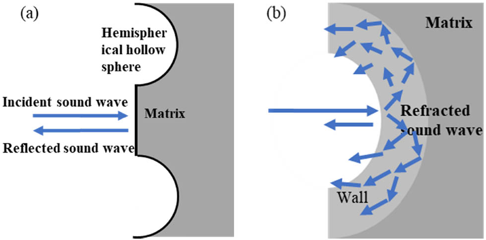
Sound absorption diagram of MHS A356 aluminum matrix composites under non-resonance conditions: (a) at matrix and (b) at the hemispherical hollow sphere.
The direction of the sound waves reflected from the wall of MHS has been altered, and the sound waves will disperse at the interface between the wall of MHS and the air. The diffuse reflection among the sound waves will consume a portion of the sound waves and lessen the amount of sound waves returned to the air [22]. Meanwhile, during the propagation of the sound waves in the spherical wall, owing to the “viscous effect” and “thermal effect,” some of the sound waves will be expended, further decreasing the amount of sound waves returned to the air. The higher the porosity of the wall is, the longer the path of the sound waves that propagate within the wall will be, and the more sound waves will be consumed by the wall. At the same time, the greater the change in the direction of the sound waves reflected into the air through the spherical wall is, the more evident the interference and noise reduction effect among the sound waves will be.
Consequently, when the MHS A356 aluminum matrix composites are not in resonance with the sound waves, the sound absorption coefficient of the MHS A356 aluminum matrix composites largely relies on the amount of hemispherical hollow spheres on the surface of the test sample and the porosity of the spherical wall. The greater the number of semi-spherical hollow spheres and the higher the porosity of the spherical wall, the larger the sound absorption coefficient of the MHS A356 aluminum matrix composites will be.
In this article, in regard to the MHS A356 aluminum matrix composites made by means of employing MHSs with the same diameter yet sintered at different temperatures, the amount of hemispherical hollow spheres on the surface of the test sample did not show obvious alteration when the volume fraction of the MHSs was the same. Nevertheless, because of the greater porosity of the spherical wall sintered at lower temperatures, the MHS A356 aluminum matrix composites produced by means of utilizing MHSs sintered at lower temperatures presented a higher sound absorption coefficient.
For MHS A356 aluminum matrix composites with diverse volume fractions of MHSs, as the fewer hemispherical hollow spheres are on the surface of the test samples with lower volume fractions of MHSs, the sound absorption coefficient of the MHS A356 aluminum matrix composites with lower volume fractions of hollow spheres is lower. Likewise, the MHS A356 aluminum matrix composites prepared with a smaller diameter of MHSs has a higher sound absorption coefficient because of the existence of more hemispherical MHSs on the surface of the test sample.
When the sound waves resonate with the MHS A356 aluminum matrix composites, the propagation mode of the sound waves within the MHS A356 aluminum matrix composites is presented in Figure 10 [25]. As can be observed from Figure 10, once the sound waves enter the MHS A356 aluminum matrix composites, they travel along the matrix. During the process of propagation, when the sound waves encounter the MHSs, due to the misalignment of the acoustic characteristic impedance between the matrix and the MHSs, the sound waves reflect and refract at the contact point between the wall and the transition layer, as depicted in Figure 10(a). At this moment, the majority of the sound waves are reflected by the spherical wall, alter their direction, and continue to travel along the matrix, as shown in Figure 10(b). Some sound waves enter the wall of the MHS through refraction, and these sound waves move along the interconnected stainless steel within the wall of the MHSs. When these sound waves travel to the interface between the wall and the air inside the MHS, the sound waves are reflected back into the wall and continue to move along the stainless steel. Eventually, the sound waves return to the matrix.
![Figure 10
The schematic diagram of sound wave propagation mechanism in MHS A356 aluminum matrix composites under resonance condition [25]: (a) at MHS and (b) in the MHS A356 aluminum matrix composites.](/document/doi/10.1515/secm-2024-0036/asset/graphic/j_secm-2024-0036_fig_010.jpg)
The schematic diagram of sound wave propagation mechanism in MHS A356 aluminum matrix composites under resonance condition [25]: (a) at MHS and (b) in the MHS A356 aluminum matrix composites.
When sound waves move through the wall, they cause the air within the MHS to vibrate. Due to the “viscous effect” and “thermal effect,” some of the sound waves are changed into thermal energy and consumed, thereby increasing the sound absorption coefficient of the MHS A356 aluminum matrix composites. After being reflected many times by the MHSs, some of the sound waves are reflected into the air, while the other part goes through the MHS A356 aluminum matrix composites, as shown in Figure 10(b). From Figure 10(b), it can be seen that the more the MHSs in the MHS A356 aluminum matrix composites, the more number of times the sound waves are reflected, and the more the sound waves are reflected into the air by the MHSs, and the fewer the sound waves pass through the MHS A356 aluminum matrix composites. Thus, when sound waves resonate with the MHS A356 aluminum matrix composites, the number of MHSs is the main element affecting the sound absorption coefficient of the MHS A356 aluminum matrix composites.
For MHS A356 aluminum matrix composites prepared with MHSs sintered at different temperatures, since the diameter and number of MHSs were the same, the difference in the number of sound wave reflections by the hollow balls was not significant. However, the porosity of the spherical wall sintered at low temperatures was higher, consuming more sound waves. Therefore, MHS A356 aluminum matrix composites prepared with MHSs sintered at lower temperatures had a higher sound absorption coefficient.
For MHS A356 aluminum matrix composites with different volume fractions of MHSs, due to the same diameter of MHSs, MHS A356 aluminum matrix composites with higher volume fractions had a higher number of MHSs, and more sound waves were reflected into the air by MHSs. Therefore, MHS A356 aluminum matrix composites with higher volume fractions had a lower sound absorption coefficient.
For MHS A356 aluminum matrix composites with different diameters of MHSs, due to the same volume fraction of MHSs, MHS A356 aluminum matrix composites prepared with smaller diameter MHSs had more MHSs, and more sound waves were reflected into the air by MHSs. Therefore, MHS A356 aluminum matrix composites with smaller diameters had a lower sound absorption coefficient.
4.2 Analysis of the sound insulation mechanism
Due to the “viscous effect” and “thermal effect,” the vibration of air in MHS A356 aluminum matrix composites consumes the energy of sound waves. Meanwhile, there is also heat exchange between the air and the substrate, which consumes some sound waves.
In addition, the density of acoustic materials also has a significant impact on the sound transmission loss of acoustic materials. The relationship between the density of acoustic materials and sound transmission loss is shown in formula (2) [23].
where
From formula (2), it can be seen that the higher the density of the acoustic material, the greater the sound transmission loss of the acoustic material.
Therefore, it can be inferred that the higher the porosity and density of MHS A356 aluminum matrix composites, the greater the sound transmission loss of MHS A356 aluminum matrix composites.
When the volume and diameter of the MHSs were the same, due to the higher porosity in the wall of MHSs sintered at low temperatures, the MHSs would consume more sound waves. However, due to the increase in the porosity of wall, the density of MHS A356 aluminum matrix composites would decrease, which would decrease the sound transmission loss of MHS A356 aluminum matrix composites. Under the combined effect of the two, the difference in sound transmission loss of MHS A356 aluminum matrix composites was not significant. In this experiment, the porosity of the wall had a greater impact on the sound transmission loss of MHS A356 aluminum matrix composites, the test results show that the sound transmission loss of MHS A356 aluminum matrix composites increased with increasing porosity of the wall. Therefore, the sound transmission loss of the MHS A356 aluminum matrix composites produced by MHSs sintered at low temperature was the highest.
When the volume fractions of MHSs were diverse, the density of the MHS A356 aluminum matrix composites rose as the volume fraction of MHSs decreased because the density of MHSs was lower compared to the matrix material. At this moment, density was the primary factor influencing the sound transmission loss of the MHS A356 aluminum matrix composites. Consequently, as the volume fraction of MHSs rose, the density of the MHS A356 aluminum matrix composites declined, resulting in a reduction in the sound transmission loss of the MHS A356 aluminum matrix composites.
When the diameters of MHSs were distinct, the MHS A356 aluminum matrix composites prepared with the smaller diameter MHSs had more interfaces, causing the sound waves to be reflected more times during the propagation process. This would make the propagation path of the sound waves in the MHS A356 aluminum matrix composites longer, consuming more sound waves. Therefore, the sound transmission loss of the MHS A356 aluminum matrix composites prepared with the smaller diameter MHSs was greater.
5 Conclusions
In this study, the MHS A356 aluminum matrix composites were produced by employing MHSs with diverse physical parameters, and their density was characterized. Moreover, the acoustic features of the MHS A356 aluminum matrix composites were gauged, and the influences of the sintering temperature, volume fraction, and diameter of MHSs on the acoustic properties of the MHS A356 aluminum matrix composites were explored. Eventually, based on the experimental outcomes, a thorough analysis of the sound absorption and insulation mechanism of the MHS A356 aluminum matrix composites was carried out. The conclusions are as follows:
When the sintering temperature of the MHS rose from 1,100 to 1,250°C, the wall porosity of the MHS decreased from 47.85 to 24.44%, along with the sound absorption coefficient of the MHS A356 aluminum matrix composites dropping from 0.19 to 0.11 and the sound transmission loss of the MHS A356 aluminum matrix composites reducing from 21.1 to 19.7 dB.
As the diameter of MHSs reduced from 5.76 to 1.55 mm, the average sound absorption coefficient of the MHS A356 aluminum matrix composites gradually rose from 0.11 to 0.23, while the average sound transmission loss of the MHS A356 aluminum matrix composites gradually decreased from 23.5 to 20.4 dB.
Along with the increase in the volume fraction of MHSs from 40.00 to 48.50%, the average sound absorption coefficient of the MHS A356 aluminum matrix composites gradually rose from 0.12 to 0.19, while the average sound transmission loss of the MHS A356 aluminum matrix composites gradually decreased from 24.6 to 21.1 dB.
Acknowledgements
The authors acknowledge the support from the West Anhui University.
-
Funding information: This study was funded by startup fee for scientific research of high-level talents in West Anhui University in 2022 (No. WGKQ2022061).
-
Author contributions: All authors have accepted responsibility for the entire content of this manuscript and consented to its submission to the journal, reviewed all the results, and approved the final version of the manuscript. CW and SC designed the experiments and MG carried them out. CW and LC prepared the manuscript with contributions from all co-authors.
-
Conflict of interest: Authors state no conflict of interest.
-
Data availability statement: The data that support the findings of this study are available from the corresponding author, upon reasonable request.
References
[1] Rabiei A, O’Neill AT. A study on processing of a composite metal foam via casting. Mater Sci Eng A. 2005;404(1-2):159–64.10.1016/j.msea.2005.05.089Search in Google Scholar
[2] Rabiei A, Vendra L, Reese N, Young N, Neville BP. Processing and characterization of a new composite metal foam. Mater Trans. 2006;47(9):2148–53.10.2320/matertrans.47.2148Search in Google Scholar
[3] Rabiei A, Vendra LJ. A comparison of composite metal foam’s properties and other comparable metal foams. Mater Lett. 2009;63(5):533–6.10.1016/j.matlet.2008.11.002Search in Google Scholar
[4] Lehmhus D, Weise J, Baumeister J, Peroni L, Scapin M, Fichera C, et al. Quasi-static and dynamic mechanical performance of glass micro-sphere- and cenosphere-based 316L syntactic foams. Proced Mater Sci. 2014;4:383–7.10.1016/j.mspro.2014.07.578Search in Google Scholar
[5] Peroni L, Scapin M, Avalle M, Weise J, Lehmhus D. Dynamic mechanical behavior of syntactic iron foams with glass microspheres. Mater Sci Eng A. 2012;552(5):364–75.10.1016/j.msea.2012.05.053Search in Google Scholar
[6] Anbuchezhiyan G, Mohan B, Sathianarayanan D, Muthuramalingam T. Synthesis and characterization of hollow glass microspheres reinforced magnesium alloy matrix syntactic foam. J Alloy Compd. 2017;719:125–32.10.1016/j.jallcom.2017.05.153Search in Google Scholar
[7] Anbuchezhiyan G, Muthuramalingam T, Mohan B. Effect of process parameters on mechanical properties of hollow glass microsphere reinforced magnesium alloy syntactic foams under vacuum die casting. Arch Civ Mech Eng. 2018;18(4):1645–50.10.1016/j.acme.2018.07.008Search in Google Scholar
[8] Chen S, Marx J, Rabiei A. Experimental and computational studies on the thermal behavior and fire retardant properties of composite metal foams. Int J Therm Sci. 2016;106:70–9.10.1016/j.ijthermalsci.2016.03.005Search in Google Scholar
[9] Wang C, Jiang F, Shao S, Yu T, Guo C. Acoustic properties of 316L stainless steel hollow sphere composites fabricated by pressure casting. Metals. 2020;10(8):1047–63.10.3390/met10081047Search in Google Scholar
[10] Yu T, Jiang F, Wang J, Wang Z, Guo C. Acoustic insulation and absorption mechanism of metallic hollow spheres composites with different polymer matrix. Compos Struct. 2020;248:1125–36.10.1016/j.compstruct.2020.112566Search in Google Scholar
[11] Chen S, Bourham M, Rabiei A. Attenuation efficiency of X-ray and comparison to gamma ray and neutrons in composite metal foams. Radiat Phys Chem. 2015;117:12–22.10.1016/j.radphyschem.2015.07.003Search in Google Scholar
[12] Chen S, Bourham M, Rabiei A. Neutrons attenuation on composite metal foams and hybrid open-cell Al foam. Radiat Phys Chem. 2015;109:27–39.10.1016/j.radphyschem.2014.11.003Search in Google Scholar
[13] Marx J, Portanova M, Rabiei A. A study on blast and fragment resistance of composite metal foams through experimental and modeling approaches. Compos Struct. 2018;194:652–61.10.1016/j.compstruct.2018.03.075Search in Google Scholar
[14] Xia X, Zhang Z, Zhao W, Li C, Ding J, Liu C, et al. Acoustic properties of closed-cell aluminum foams with different macrostructures. J Mater Sci Technol. 2017;33(11):1227–34.10.1016/j.jmst.2017.07.012Search in Google Scholar
[15] Li Y, Wang X, Wang X, Ren Y, Han F, Wen C. Sound absorption characteristics of aluminum foam with spherical cells. J Appl Phys. 2011;110(11):559.10.1063/1.3665216Search in Google Scholar
[16] Bao HQ, Zhang N, Hou XG. Analysis of the influence of static flow resistance on the sound absorption properties of aluminum foam. Adv Mater. 2012;535:1459–62.10.4028/www.scientific.net/AMR.535-537.1459Search in Google Scholar
[17] Sun JX, Duan CY, Liu PS. Sound absorption characterization of aluminum foam made by press infiltration casting multidiscip. Model Mater Struct. 2016;12:737–47.10.1108/MMMS-03-2016-0010Search in Google Scholar
[18] Liu PS, Qing HB, Hou HL. Primary investigation on sound absorption performance of highly porous titanium foams. Mater Des. 2015;85(15):275–81.10.1016/j.matdes.2015.06.118Search in Google Scholar
[19] Zhou R, Crocker MJ. Sound transmission loss of foam-filled honeycomb sandwich panels using statistical energy analysis and theoretical and measured dynamic properties. J Sound Vibr. 2010;329(6):673–86.10.1016/j.jsv.2009.10.002Search in Google Scholar
[20] Komatsu T. Improvement of the Delany-Bazley and Miki models for fibrous sound-absorbing materials. Acoust Sci Technol. 2008;29(2):121–9.10.1250/ast.29.121Search in Google Scholar
[21] Zhang XH, Qu ZG, Tian D, Fang Y. Acoustic characteristics of continuously graded phononic crystals. Appl Acoust. 2019;151:22–9.10.1016/j.apacoust.2019.03.002Search in Google Scholar
[22] Wang XF, Wang XF, Wei X, Han FS, Wang XL. Sound absorption of open celled aluminium foam fabricated by investment casting method. Mater Sci Tech-Lond. 2013;27(4):800–4.10.1179/026708309X12506934374047Search in Google Scholar
[23] Xiao Y, Wen JH, Wen XS. Sound transmission loss of metamaterial-based thin plates with multiple subwavelength arrays of attached resonators. J Sound Vibr. 2012;331(25):5408–23.10.1016/j.jsv.2012.07.016Search in Google Scholar
[24] Wang C, Jiang F, Qin R, Guo C. Preparation and characterization of 316L stainless steel hollow sphere prepared by powder metallurgy. J Mater Eng Perform. 2022;2:31–42.10.1007/s11665-021-06246-6Search in Google Scholar
[25] Wang C, Guo C, Jiang F Investigation on the acoustic properties of structural gradient 316L stainless steel hollow spheres composites. Sci Eng Compos Mater 2021;28(1):478–88.10.1515/secm-2021-0046Search in Google Scholar
© 2024 the author(s), published by De Gruyter
This work is licensed under the Creative Commons Attribution 4.0 International License.
Articles in the same Issue
- Regular Articles
- Research on damage evolution mechanisms under compressive and tensile tests of plain weave SiCf/SiC composites using in situ X-ray CT
- Structural optimization of trays in bolt support systems
- Continuum percolation of the realistic nonuniform ITZs in 3D polyphase concrete systems involving the aggregate shape and size differentiation
- Multiscale water diffusivity prediction of plain woven composites considering void defects
- The application of epoxy resin polymers by laser induction technologies
- Analysis of water absorption on the efficiency of bonded composite repair of aluminum alloy panels
- Experimental research on bonding mechanical performance of the interface between cementitious layers
- A study on the effect of microspheres on the freeze–thaw resistance of EPS concrete
- Influence of Ti2SnC content on arc erosion resistance in Ag–Ti2SnC composites
- Cement-based composites with ZIF-8@TiO2-coated activated carbon fiber for efficient removal of formaldehyde
- Microstructure and chloride transport of aeolian sand concrete under long-term natural immersion
- Simulation study on basic road performance and modification mechanism of red mud modified asphalt mixture
- Extraction and characterization of nano-silica particles to enhance mechanical properties of general-purpose unsaturated polyester resin
- Roles of corn starch and gellan gum in changing of unconfined compressive strength of Shanghai alluvial clay
- A review on innovative approaches to expansive soil stabilization: Focussing on EPS beads, sand, and jute
- Experimental investigation of the performances of thick CFRP, GFRP, and KFRP composite plates under ballistic impact
- Preparation and characterization of titanium gypsum artificial aggregate
- Characteristics of bulletproof plate made from silkworm cocoon waste: Hybrid silkworm cocoon waste-reinforced epoxy/UHMWPE composite
- Experimental research on influence of curing environment on mechanical properties of coal gangue cementation
- Multi-objective optimization of machining variables for wire-EDM of LM6/fly ash composite materials using grey relational analysis
- Synthesis and characterization of Ag@Ni co-axial nanocables and their fluorescent and catalytic properties
- Beneficial effect of 4% Ta addition on the corrosion mitigation of Ti–12% Zr alloy after different immersion times in 3.5% NaCl solutions
- Study on electrical conductive mechanism of mayenite derivative C12A7:C
- Fast prediction of concrete equivalent modulus based on the random aggregate model and image quadtree SBFEM
- Research on uniaxial compression performance and constitutive relationship of RBP-UHPC after high temperature
- Experimental analysis of frost resistance and failure models in engineered cementitious composites with the integration of Yellow River sand
- Influence of tin additions on the corrosion passivation of TiZrTa alloy in sodium chloride solutions
- Microstructure and finite element analysis of Mo2C-diamond/Cu composites by spark plasma sintering
- Low-velocity impact response optimization of the foam-cored sandwich panels with CFRP skins for electric aircraft fuselage skin application
- Research on the carbonation resistance and improvement technology of fully recycled aggregate concrete
- Study on the basic properties of iron tailings powder-desulfurization ash mine filling cementitious material
- Preparation and mechanical properties of the 2.5D carbon glass hybrid woven composite materials
- Improvement on interfacial properties of CuW and CuCr bimetallic materials with high-entropy alloy interlayers via infiltration method
- Investigation properties of ultra-high performance concrete incorporating pond ash
- Effects of binder paste-to-aggregate ratio and polypropylene fiber content on the performance of high-flowability steel fiber-reinforced concrete for slab/deck overlays
- Interfacial bonding characteristics of multi-walled carbon nanotube/ultralight foamed concrete
- Classification of damping properties of fabric-reinforced flat beam-like specimens by a degree of ondulation implying a mesomechanic kinematic
- Influence of mica paper surface modification on the water resistance of mica paper/organic silicone resin composites
- Impact of cooling methods on the corrosion behavior of AA6063 aluminum alloy in a chloride solution
- Wear mechanism analysis of internal chip removal drill for CFRP drilling
- Investigation on acoustic properties of metal hollow sphere A356 aluminum matrix composites
- Uniaxial compression stress–strain relationship of fully aeolian sand concrete at low temperatures
- Experimental study on the influence of aggregate morphology on concrete interfacial properties
- Intelligent sportswear design: Innovative applications based on conjugated nanomaterials
- Research on the equivalent stretching mechanical properties of Nomex honeycomb core considering the effect of resin coating
- Numerical analysis and experimental research on the vibration performance of concrete vibration table in PC components
- Assessment of mechanical and biological properties of Ti–31Nb–7.7Zr alloy for spinal surgery implant
- Theoretical research on load distribution of composite pre-tightened teeth connections embedded with soft layers
- Coupling design features of material surface treatment for ceramic products based on ResNet
- Optimizing superelastic shape-memory alloy fibers for enhancing the pullout performance in engineered cementitious composites
- Multi-scale finite element simulation of needle-punched quartz fiber reinforced composites
- Thermo-mechanical coupling behavior of needle-punched carbon/carbon composites
- Influence of composite material laying parameters on the load-carrying capacity of type IV hydrogen storage vessel
- Review Articles
- Effect of carbon nanotubes on mechanical properties of aluminum matrix composites: A review
- On in-house developed feedstock filament of polymer and polymeric composites and their recycling process – A comprehensive review
- Research progress on freeze–thaw constitutive model of concrete based on damage mechanics
- A bibliometric and content analysis of research trends in paver blocks: Mapping the scientific landscape
- Bibliometric analysis of stone column research trends: A Web of Science perspective