A study on the effect of microspheres on the freeze–thaw resistance of EPS concrete
-
Haijie He
 ,
Wei Ge
,
Wei Ge

Abstract
This study investigated the influence of microbead dosages (0, 5, 10, 15, and 20%) on the frost resistance of expanded polystyrene (EPS) concrete. Five groups of EPS concrete specimens were prepared and subjected to rapid freeze–thaw tests. The freeze–thaw deterioration of EPS concrete was assessed using macroscopic indicators, including mass loss, strength loss, and dynamic elastic modulus loss. The underlying deterioration mechanism was revealed through the analysis of the EPS particle–matrix interface. A concrete damage plasticity model of EPS concrete based on damage mechanics theory was established. The results indicate that the addition of microbeads increased the strength of EPS concrete by 38–53%, reduced the strength attenuation after freeze–thaw damage by 8.1%, and improved the frost resistance level by 10–60 grades. The optimal dosage of microbeads is 15% of the cementitious material. The interfacial transition zone gaps in EPS concrete with added microbeads after freeze–thaw cycles are smaller, contributing to a more complete hydration reaction. The freeze–thaw damage model established in this study accurately reflects the freeze–thaw damage law of EPS concrete and provides a reference for studying the mechanical properties of EPS concrete under freeze–thaw cycles. The research findings of this study can enhance the strength and service life of EPS concrete, expanding its application scope as a structural material. The study provides valuable insights for future research and engineering applications related to the frost resistance of EPS concrete.
1 Introduction
In recent years, the development of low-carbon buildings has led to an increase in the application of expanded polystyrene (EPS) concrete [1,2,3,4,5,6,7,8,9]. As a structural material in walls, the durability of EPS concrete directly affects the safety of the structure [10,11,12,13,14,15,16]. Frost resistance is a crucial factor influencing concrete durability [17], and an inevitable connection exists between EPS concrete’s frost resistance and the structure’s service life. Enhancing EPS concrete’s frost resistance and extending its service life are important technical means to promote its use. However, current research on EPS concrete’s frost resistance and durability is limited. Improving the durability of EPS concrete can significantly impact the quality of EPS concrete structures and expand their application scope.
Presently, there are two main approaches to improve the frost resistance of EPS concrete. The first approach involves applying protective coatings to the surface of EPS concrete. Guo [18] applied a frost-resistant agent to EPS concrete, which significantly improved its frost resistance. Guan [19] used waterproofing agents such as organic silane on the surface of EPS concrete, resulting in a substantial improvement in frost resistance. The second approach focuses on modifying EPS concrete. Hu [20] incorporated polyvinyl alcohol (PVA) fibers into EPS concrete, which improved its frost resistance. Yuan et al. [15] modified the surface of EPS particles by encapsulation, altering the hydrophilicity of the EPS particle surface to enhance interfacial bonding performance and significantly improve EPS concrete’s frost resistance. While these methods effectively improve EPS concrete’s frost resistance, they introduce construction difficulties or increase application costs, hindering its promotion. A simple and economical method to enhance EPS concrete’s durability would significantly contribute to its promotion and application. Currently, there are potential methods to enhance the performance of concrete, such as incorporating carbon nanotubes [21,22], adding polylactic acid [23], and utilizing boron-enriched nanosized particles [24,25]. These materials may be effective in enhancing the performance of EPS concrete. The authors propose that adding mineral admixtures is a promising approach to improve EPS concrete’s durability. Mineral admixtures have been proven to significantly enhance the strength and durability of ordinary concrete [26]. In this study, a new type of mineral admixture, microbeads, was added to EPS concrete to improve its performance.
Microbeads [15,26] are ultrafine particles collected from the smoke emitted by coal-fired power plants. They not only reduce air pollution but also serve as a newly developed special resource. Microbeads have a continuous and uniform particle size distribution, which can act as a compact filler in mortar and concrete, reducing capillary pores. They synergize well with chemical corrosion inhibitors and waterproofing agents, enhancing corrosion resistance and impermeability. Their unique physicochemical properties can increase the compactness of mortar or concrete, reduce harmful capillary pores and microcracks, and thus enhance the corrosion and permeability resistance of mortar and concrete. Microbead anticorrosion and waterproofing agents used in silicate cement mortar or concrete can resist the corrosion of certain concentrations of
In this study, EPS concrete samples with a density of 1,100 kg/m3 were prepared with microbead admixtures at different dosages: 0, 5, 10, 15, and 20% of the cementitious materials. The durability of EPS concrete after 0, 25, 50, 75, 100, 125, 150, and 175 freeze–thaw cycles was investigated using scanning electron microscopy (SEM) to provide theoretical support for the engineering application of EPS concrete.
2 Experimental scheme
2.1 Raw materials
The cement used was P.O 42.5 with a specific surface area of 400 m2/kg, an average particle size of approximately 10–20 μm, and 3 days and 28 days strengths of 24.6 MPa and 46.3 MPa, respectively [27]. The sand was washed sea sand with an apparent density of 2,630 kg/m3 and a fineness modulus of 2.60. The fly ash was Class II fly ash [28] produced by Taizhou Tianda Environmental Protection Building Materials Co., Ltd. The microbeads were produced by Tianjin Zhucheng New Material Technology Co., Ltd, with an apparent density of 2,520 kg/m3, a bulk density of 760 kg/m3, a specific surface area of greater than 1,300 m2/kg, 28 days and 56 days activity coefficients of 105–110% and 115–120%, respectively, and a corrosion resistance coefficient index of 0.96. The microbeads and scanning electron micrographs are shown in Figure 1. The water reducer used was a polycarboxylic acid water reducer with a solid content of 20%. The particle size of EPS was 2–3 mm, and the bulk density was 17.6 kg/m3, as illustrated in Figure 2. In the composite powder of cement, microbeads, and fly ash, microbeads fill the pores between the cement and fly ash particles to form a compact cementitious material. The particle size distribution (PSD) of three powder materials (cement, microbeads, and fly ash) was determined using a laser particle size analyzer, as plotted in Figure 3. The chemical compositions obtained using X-ray fluorescence (XRF) testing are provided in Table 1.
![Figure 1
Microbeads and their scanning electron micrographs [11,14].](/document/doi/10.1515/secm-2022-0241/asset/graphic/j_secm-2022-0241_fig_001.jpg)

EPS foam particles.
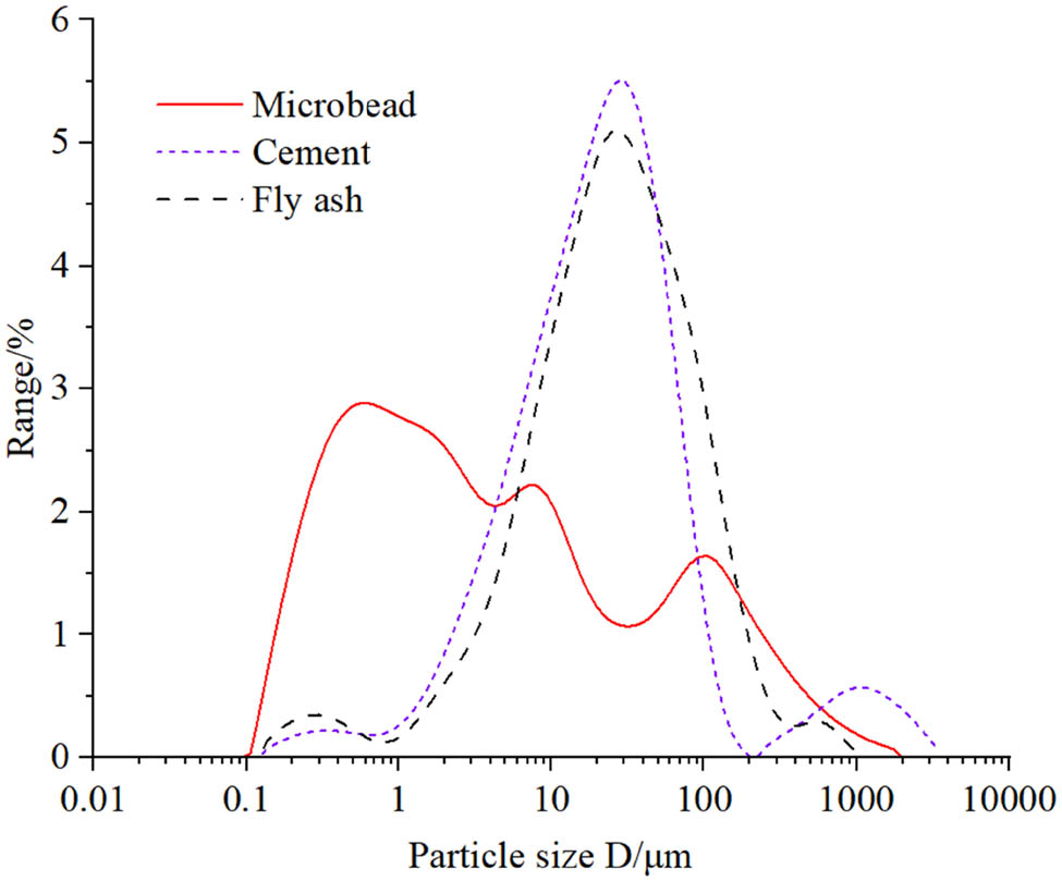
PSD of solid materials used in the mixtures.
Chemical composition of the cementitious material
| Chemical composition (%) | SiO2 | CaO | MgO | Al2O3 | Fe2O3 | Na2O | K2O | SO3 | TiO2 |
|---|---|---|---|---|---|---|---|---|---|
| Microbeads | 56.52 | 4.85 | 1.33 | 26.54 | 5.36 | 1.42 | 3.28 | 0.65 | 0.02 |
| Cement | 22.93 | 58.42 | 1.81 | 6.93 | 3.43 | 0.37 | 1.13 | 3.75 | 0.48 |
| Fly ash | 34.48 | 4.62 | 0.60 | 42.35 | 9.88 | 0.48 | 1.42 | 2.15 | 2.51 |
2.2 EPS concrete mix proportion design
In this study, five groups of EPS particle specimens were designed, maintaining the total amount of cementitious materials constant for each group. Group 1 was the blank control group with no microbead addition. Groups 2, 3, 4, and 5 contained microbead admixtures of 5, 10, 15, and 20% of the cementitious material, respectively, replacing the fly ash in Group 1 with corresponding microbead dosages. The mix proportions for the five groups of EPS concrete specimens are shown in Table 2.
Mix proportion of EPS concrete
| Group | Cement/kg | Fly ash/kg | Polyphenyl particle/L | Water/kg | Water reducer/kg | Mircobead/kg | Cementitious material replacement ratio (%) |
|---|---|---|---|---|---|---|---|
| 1# | 370 | 370 | 580 | 252 | 3.5 | 0 | 0 |
| 2# | 370 | 333 | 580 | 252 | 3.5 | 37 | 5 |
| 3# | 370 | 296 | 580 | 252 | 3.5 | 74 | 10 |
| 4# | 370 | 259 | 580 | 252 | 3.5 | 111 | 15 |
| 5# | 370 | 222 | 580 | 252 | 3.5 | 148 | 20 |
2.3 Specimen preparation and curing
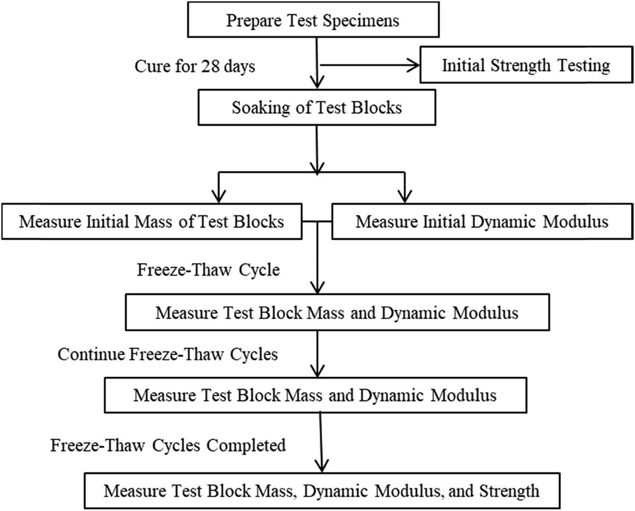
The specimen preparation for this experiment followed the “Standard for test methods of concrete physical and mechanical properties” (GB/T50081-2019) [29]. For each group of EPS concrete, three sets of cubic specimens (100 mm × 100 mm × 100 mm) and one set of prismatic specimens (100 mm × 100 mm × 400 mm) were prepared, with three specimens in each set. One set of cubic specimens was used for testing the 28 days curing strength, one set for testing the strength after freeze–thaw cycles, one set for microscopic testing, and the prismatic specimens for freeze–thaw testing. After molding, the EPS concrete specimens were placed in a natural curing room, and the molds were removed after one day and transferred to a standard curing room for curing. The dry density of the specimens in each group is shown in Figure 4, and the dry density of all five groups of EPS concrete was 1,100 kg/m3. The main experimental process is provided in Figure 5.
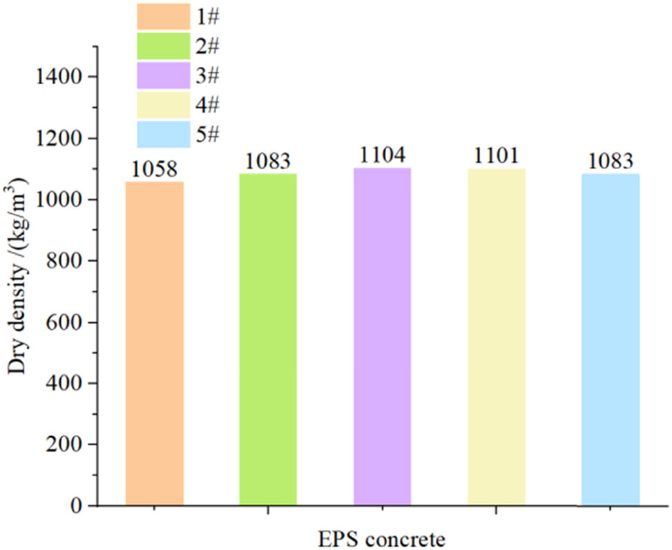
Dry density of the specimens.
Main experimental flowchart.
2.4 Freeze–thaw testing
In this experiment, a TDRF-2 rapid freeze–thaw box for concrete was used, and the test was conducted using the rapid freezing method as per “Standard for test methods of long-term performance and durability of ordinary concrete” (GB/T50082-2009). The experimental procedure is illustrated in Figure 6. The freezing temperature range was −18 to −20°C, with a freezing time of 4 h, while the thawing temperature range was 18−20°C, with a thawing time of 4 h. After every 25 freeze–thaw cycles, the mass, dynamic elastic modulus, and compressive strength were measured using an electronic balance, a concrete dynamic modulus tester, and a pressure testing machine, respectively [30].
Experimental procedure.
2.5 Microscopic testing
To reveal the microscopic deterioration rules of EPS concrete under freeze–thaw cycles, SEM was used for the microstructure analysis. The experiment was conducted at the Material Science Institute of Taizhou University. A Hitachi S-4800 field emission SEM was employed to test EPS concrete before and after freeze–thaw cycles. The specific steps were: (1) sample preparation; (2) gold sputtering treatment of the sample; (3) placing the sample and adjusting its position; (4) vacuuming; (5) emitting electron beams; (6) observing and taking photographs; and (7) sampling.
3 Results and discussion
3.1 Freeze–thaw damage phenomena
3.1.1 Group 1
The apparent morphology changes of Group 1 of EPS concrete during the freeze–thaw process are shown in Figure 7. After 25 freeze–thaw cycles, EPS foam particles on the specimen surface began to fall off. After 50 freeze–thaw cycles, specimens 1–1 and 1–3 fractured, and the specimens were damaged by freeze–thaw.
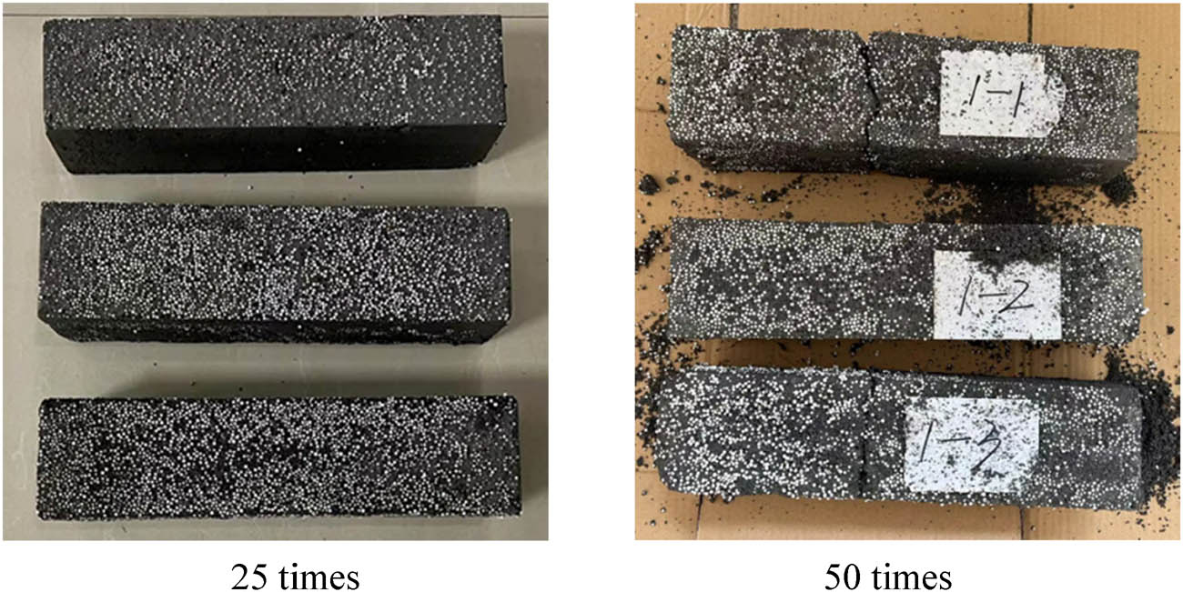
Freeze–thaw damage morphology of Group 1 specimens.
3.1.2 Group 2
The apparent morphology changes of Group 2 of EPS concrete during the freeze–thaw process are provided in Figure 8. After 25 freeze–thaw cycles, EPS foam particles on the specimen surface began to fall off. After 50 freeze–thaw cycles, the mortar on the specimen surface fell off. After 75 freeze–thaw cycles, specimen 2–3 fractured, and the mortar on the specimen surface fell off further. After 100 freeze–thaw cycles, specimen 2–2 fractured, the specimen ends became flat, and the concrete surface and edges displayed severe spalling.
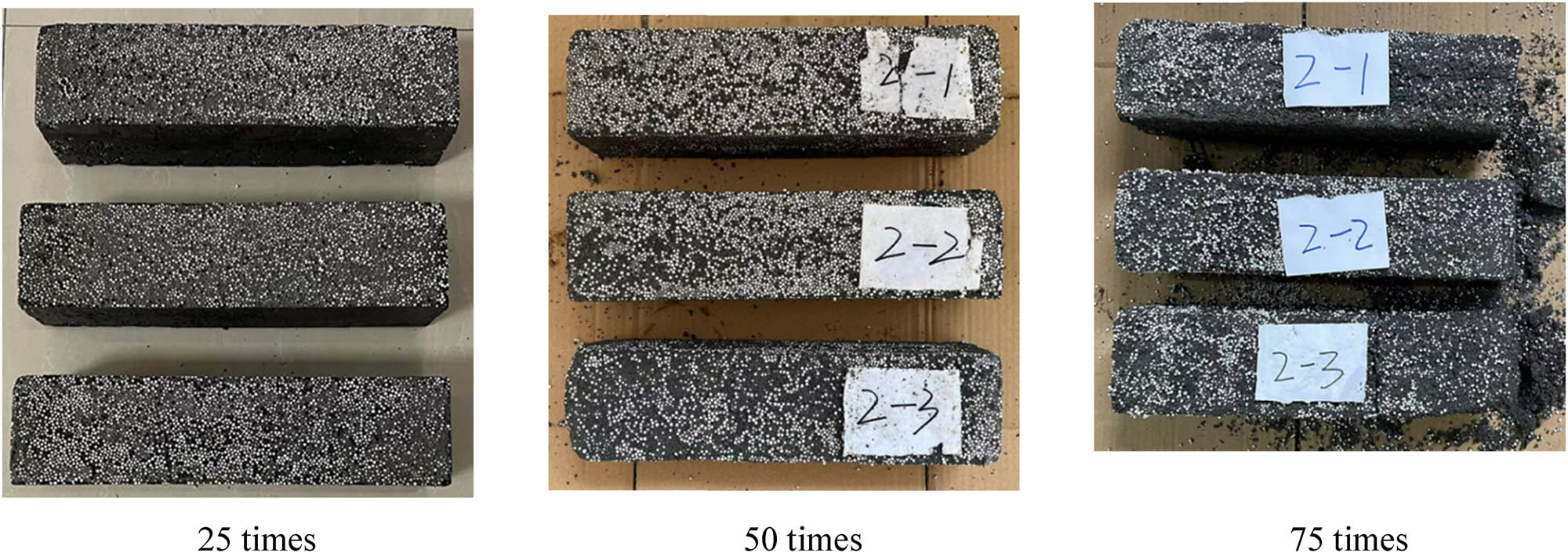
Freeze–thaw damage morphology of Group 2 specimens.
3.1.3 Group 3
The apparent morphology changes of Group 3 of EPS concrete during the freeze–thaw process are plotted in Figure 9. After 25 freeze–thaw cycles, EPS foam particles on the specimen surface began to fall off. After 50 freeze–thaw cycles, the mortar on the specimen surface fell off, and specimen 3–3 fractured. After 75 freeze–thaw cycles, the mortar on the specimen surface fell off further, and the specimen end was severely damaged. After 100 freeze–thaw cycles, specimen 3–1 fractured, and the specimen end became flat.
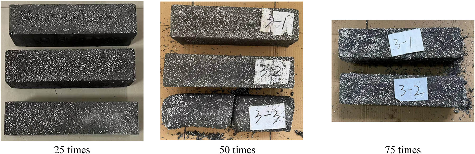
Freeze–thaw damage morphology of Group 3 specimens.
3.1.4 Group 4
The apparent morphology changes of Group 4 of EPS concrete during the freeze–thaw process are illustrated in Figure 10. After 25 freeze–thaw cycles, EPS foam particles on the specimen surface began to fall off. After 50 freeze–thaw cycles, the mortar on the specimen surface fell off. After 75 freeze–thaw cycles, the mortar on the specimen surface fell off further, and the specimen end was damaged. After 100 freeze–thaw cycles, the specimen end was further damaged, the mortar on the specimen end fell off, and the end was severely damaged. After 125 freeze–thaw cycles, specimen 4–2 fractured and the specimen end became flat.
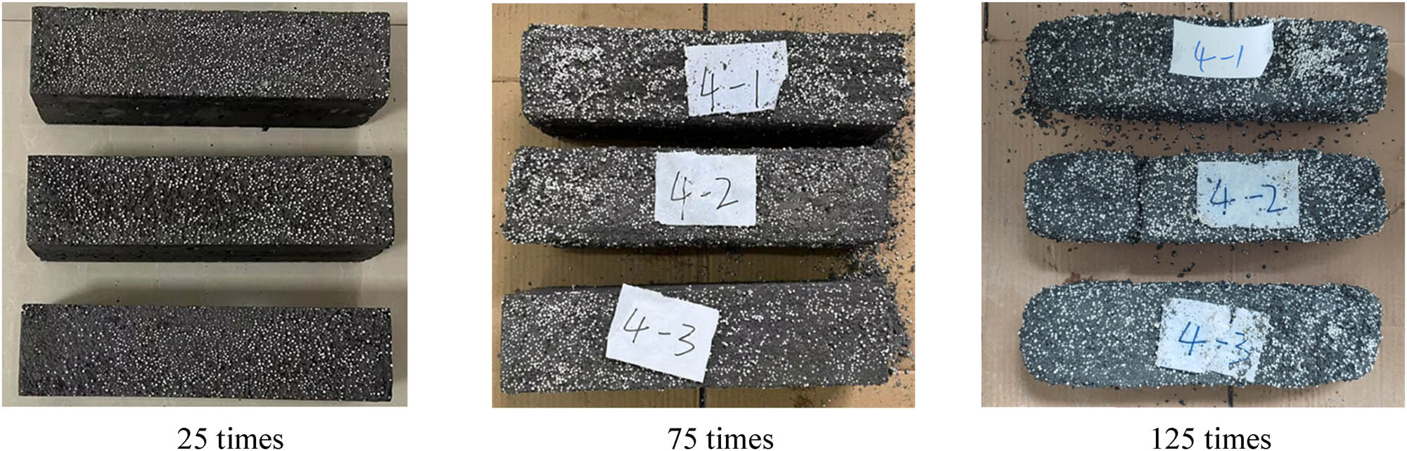
Freeze–thaw damage morphology of Group 4 specimens.
3.1.5 Group 5
The apparent morphology changes of Group 5 of EPS concrete during the freeze–thaw process are depicted in Figure 11. After 25 freeze–thaw cycles, EPS foam particles on the specimen surface began to fall off. After 50 freeze–thaw cycles, the mortar on the specimen surface fell off. After 75 freeze–thaw cycles, the mortar on the specimen surface fell off further, and the specimen end was damaged. After 100 freeze–thaw cycles, the specimen end was further damaged, and the mortar on the specimen end fell off. After 125 freeze–thaw cycles, specimen 5–2 fractured.
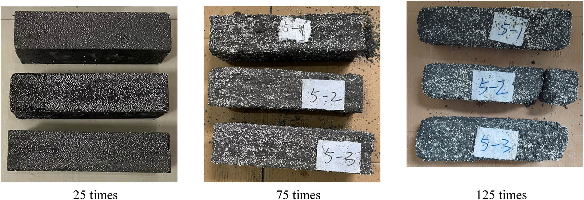
Freeze–thaw damage morphology of Group 5 specimens.
3.2 Mass loss rate
The mass changes and mass loss rates of the five EPS concrete groups are shown in Figure 12. Within 50 freeze–thaw cycles, the mass of the specimens increases, as the water absorption mass of the EPS concrete is greater than the spalling mass in the initial stage. When the number of freeze–thaw cycles exceeded 50, the internal cracks in the specimens gradually increased, and the freeze–thaw damage continued to increase, resulting in a larger mass loss rate. When the freeze–thaw reached 75 cycles, the mass loss rate curve still rose relatively gently. After the freeze–thaw exceeded 75 cycles, the mass loss curve rose significantly, with severe spalling on the EPS concrete surface and freeze–thaw damage.
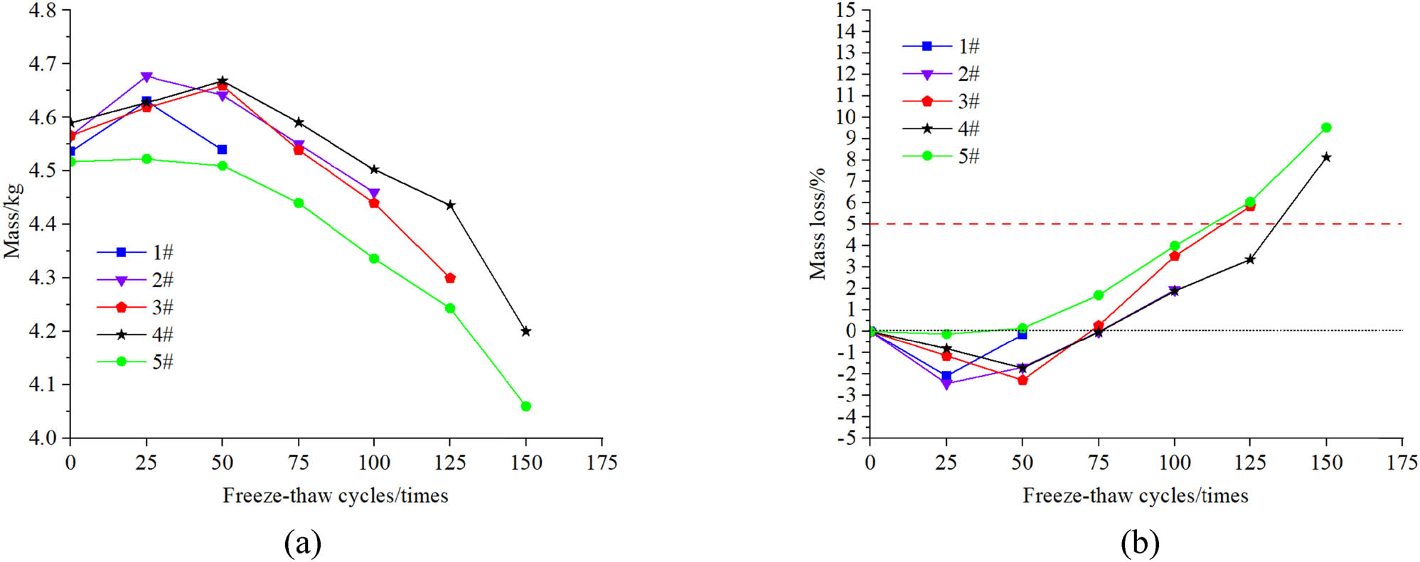
Mass change of specimens during the freeze–thaw process. (a) Mass change of EPS concrete. (b) Mass loss rate of EPS concrete.
3.3 Strength degradation
The specimens of each group before and after freeze–thaw are provided in Figure 13(a), and the strength degradation ratios of each group after freeze–thaw damage are plotted in Figure 13(b). As seen in Figure 13, after the addition of microbeads, the 28 days strength of EPS concrete was higher than that of EPS concrete without microbeads, with a strength increase of 38–53%. After freeze–thaw, the strength degradation of the specimens in Groups 1, 2, and 3 was more significant, while the strength degradation of specimens in Groups 4 and 5 was insignificant. The incorporation of microbeads significantly impacts the strength of EPS concrete, with a strength degradation rate of 15–25% after freeze–thaw. The higher the strength of EPS concrete, the smaller the strength degradation rate of freeze–thaw damage. The addition of microbeads can effectively alleviate the strength loss of EPS concrete under freeze–thaw conditions, and the strength degradation is significantly slowed down.
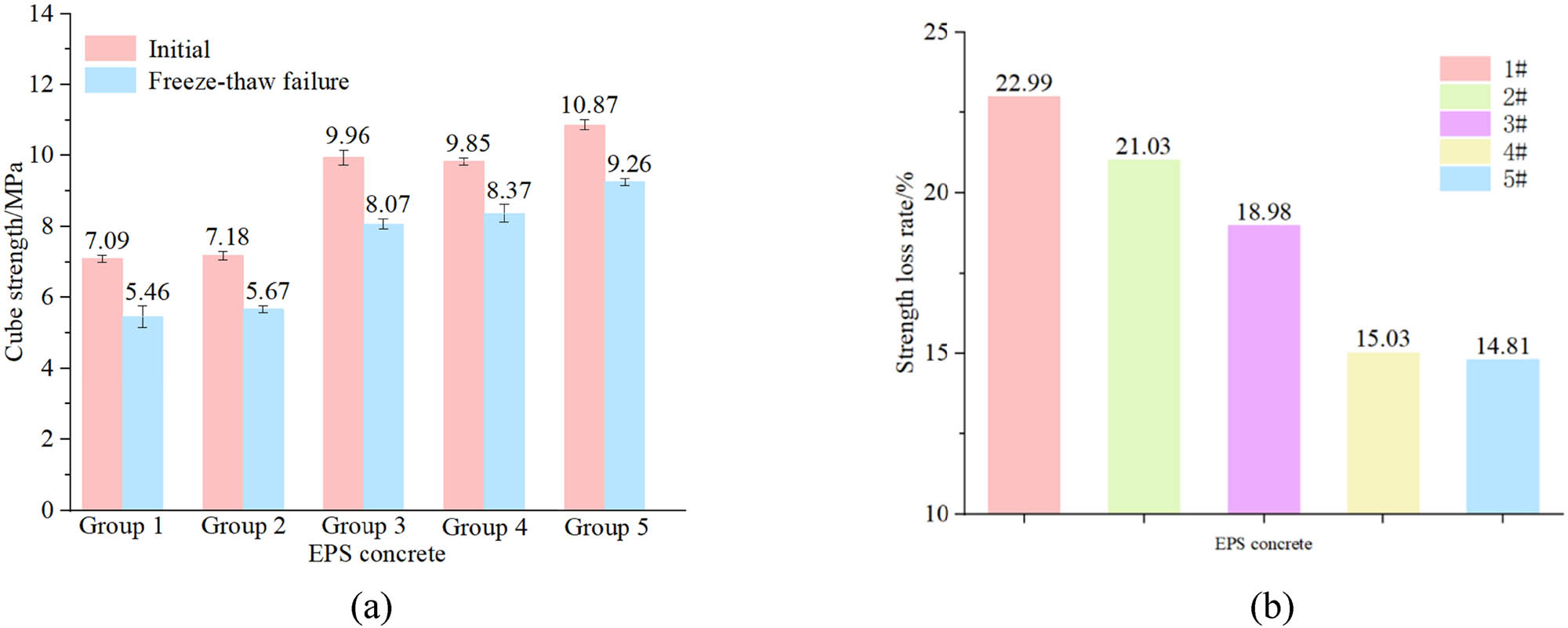
Freeze–thaw strength degradation of EPS concrete. (a) Strength before and after freeze–thaw. (b) Strength loss rate of EPS concrete.
3.4 Dynamic elastic modulus loss rate
The attenuation curves of the relative dynamic elastic modulus of the five EPS concrete groups with freeze–thaw cycles are illustrated in Figure 14. The relative dynamic elastic modulus of Groups 1, 2, and 3 decreased linearly. For Group 1, the relative dynamic elastic modulus had already dropped below 60% after 25 freeze–thaw cycles. For Groups 2 and 3, the relative dynamic elastic modulus dropped below 60% after 50 freeze–thaw cycles. The attenuation curves of the relative dynamic elastic modulus of Groups 4 and 5 basically coincided, and the relative dynamic elastic modulus dropped below 60% only after 100 freeze–thaw cycles. The relative dynamic elastic modulus of the specimens decreases with the increase in the number of freeze–thaw cycles, and the internal damage of EPS concrete accumulates continuously. According to the analysis, the addition of microbeads can improve the internal structure of EPS concrete, thereby enhancing its frost resistance. However, there is an optimal microbead dosage. When the microbead dosage was 15 and 20%, the dynamic elastic modulus attenuation curves of Groups 4 and 5 basically remained the same. In this experiment, the optimal microbead dosage for EPS concrete was 15%.
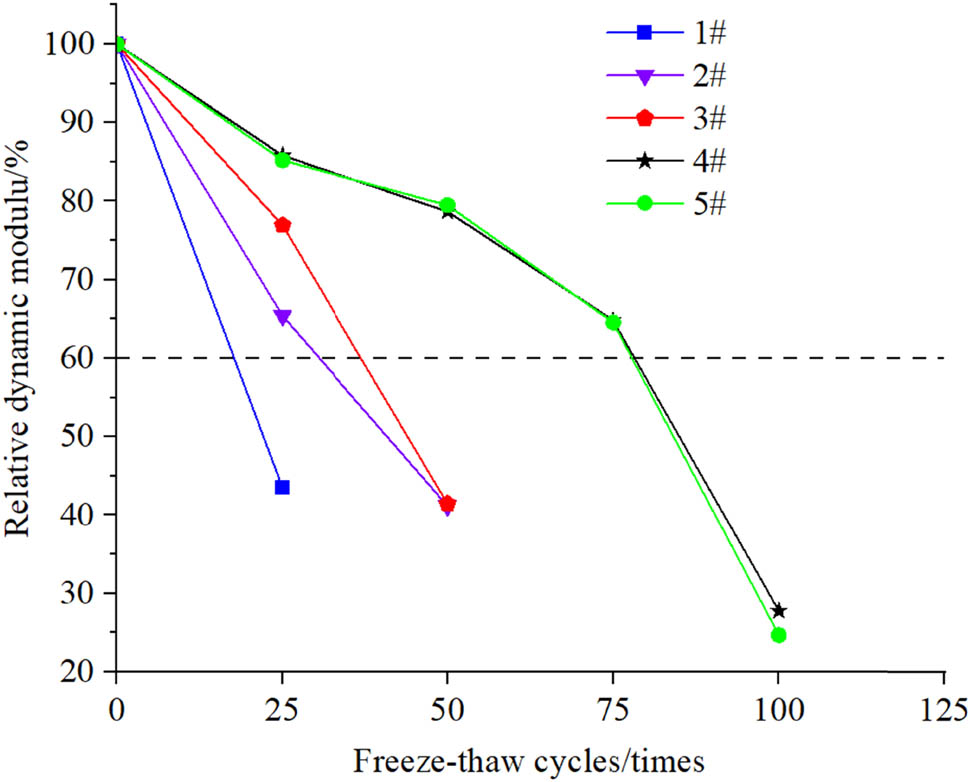
Dynamic elastic modulus change of the specimens during freeze–thaw process.
3.5 Durability index
The frost durability index of EPS concrete was based on the “Standard for test methods of long-term performance and durability of ordinary concrete” (GB/T50082-2009) and the experimental phenomenon [30]. The frost resistance mark was determined by the maximum number of freeze–thaw cycles when the relative dynamic elastic modulus was not less than 60%, the compressive strength loss rate did not exceed 25%, and the mass loss rate did not exceed 5%. In this experiment, the frost resistance class determined by the relative dynamic elastic modulus is relatively more accurate, so it is more suitable to use the relative dynamic elastic modulus value to determine the frost durability index of EPS concrete. Among them, the relative dynamic modulus of Group 1 was less than 60% after 25 freeze–thaw cycles, and the number of freeze–thaw cycles corresponding to the relative dynamic modulus of 60% was more than 15 times calculated by the interpolation method. Therefore, the frost durability index of Group 1 was set to 15 times in this test.
The frost durability index of the five EPS concrete groups is plotted in Figure 15. The frost durability index of EPS concrete without microbeads was the lowest, and those of EPS concrete with microbead dosages of 15 and 20% were the highest. Adding an appropriate amount of microbeads to EPS concrete can significantly improve the frost durability index of the concrete, with an increase of 66.6–400%. This is sufficient to show that the addition of microbeads can significantly improve the frost resistance of EPS concrete. The fundamental reason is that after adding microbeads, the interfacial transition zone (ITZ) of EPS concrete becomes denser, the ITZ’s loose structure is improved, the crack propagation is slowed down under the action of freeze–thaw cycles, and the time required for frost heave damage is longer.
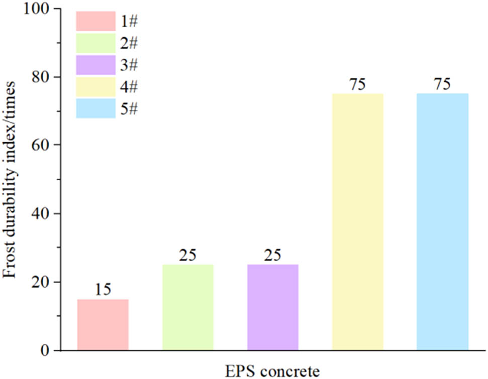
Frost durability index of EPS concrete.
According to the “Technical specification for lightweight aggregate concrete” JGJ51-2002 [26], the requirements for the frost resistance of lightweight aggregate concrete are tabulated in Table 3. According to the requirements of Table 3, it can be seen that Group 1 of EPS concrete is only suitable for non-heating areas, while Groups 2 and 3 of EPS concrete are suitable for heating areas with a relative humidity of less than or equal to 60%, and Groups 4 and 5 are suitable for heating areas with a relative humidity greater than 60% or in areas with alternating dry and wet conditions and changing water levels. After adding microbeads to EPS concrete, the application scope of EPS concrete has been expanded.
Frost durability index of lightweight aggregate concrete under different usage conditions [31]
| Service condition | Frost resistance mark |
|---|---|
| Non-heating areas | F15 |
| Heating areas | |
| Relative humidity ≤ 60% | F25 |
| Relative humidity>60% | F35 |
| Areas with alternating dry and wet conditions and changing water levels | F50 |
3.6 Microscopic characterization of freeze–thaw deterioration of EPS concrete
The freeze–thaw cycle process is actually the process of continuous loading and unloading inside the specimen. Freezing is equivalent to the loading process, and thawing is equivalent to the unloading process. From a microscopic perspective, it can be explained as the hydration product structure changing from dense to sparse, microscopic cracks gradually developing, and ITZ continuously deteriorating [32]. In order to reveal the freeze–thaw deterioration mechanism of EPS concrete and analyze the EPS concrete with different microbead dosages, the internal ITZ structure and hydration products of EPS concrete after freeze–thaw cycles were analyzed through SEM, as presented in Figures 16 and 17, respectively.
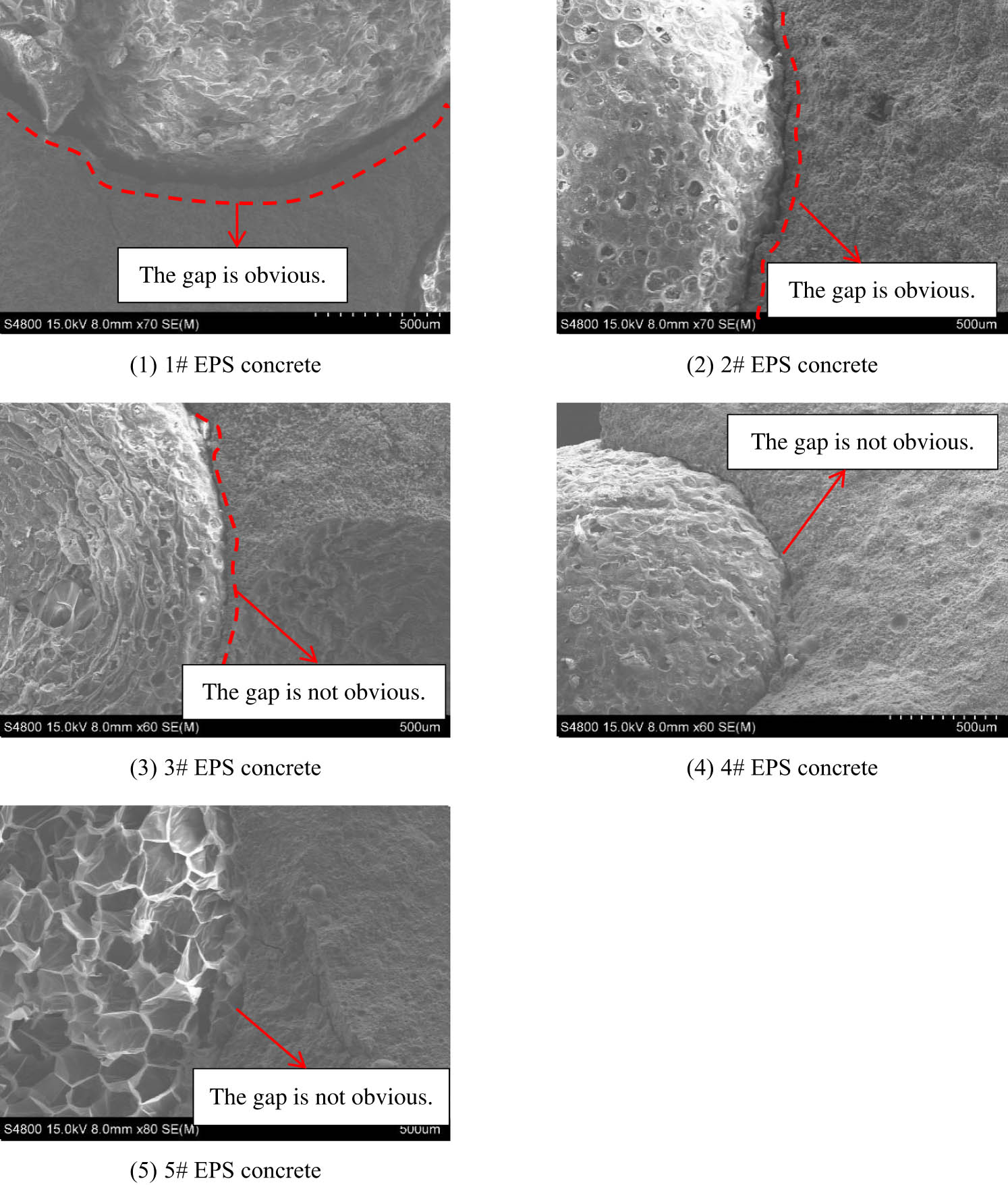
ITZ structures of EPS concrete after freeze–thaw. (1) 1# EPS concrete. (2) 2# EPS concrete. (3) 3# EPS concrete. (4) 4# EPS concrete. (5) 5# EPS concrete.
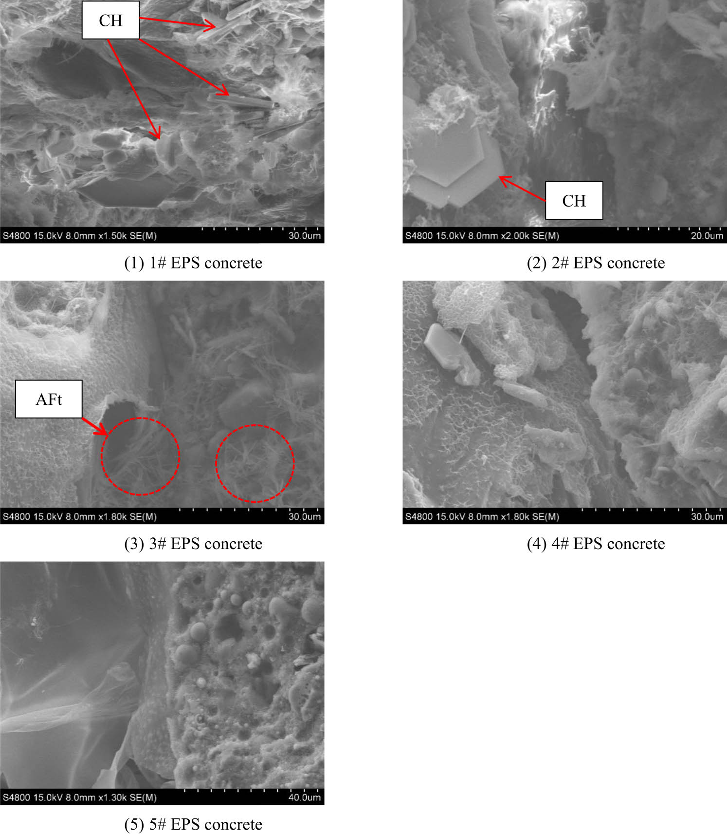
Hydration product structure after freeze–thaw. (1) 1# EPS concrete. (2) 2# EPS concrete. (3) 3# EPS concrete. (4) 4# EPS concrete. (5) 5# EPS concrete.
Figure 16 shows the ITZ structure of the five EPS concrete groups. From Figure 16, it can be seen that the ITZ structure of EPS concrete was significantly damaged after freeze–thaw, with obvious pores and cracks on the structure surface. As shown in Figure 16(1), when the replacement ratio was 0%, the ITZ structure exhibited the most severe deterioration, the structure began to loosen, and there were obvious cracks between EPS and the cement matrix. As shown in Figure 15(2), when the replacement ratio reached 5%, there were obvious gaps between the cement matrix and EPS, and cracks appeared between EPS particles and the cement matrix, but the crack width was smaller compared to the replacement ratio 0% case. As depicted in Figure 16(3), (4), and (5), when the replacement ratio was 10, 15, and 20%, the ITZ deterioration degree was significantly reduced compared to the cases of 0 and 5% replacement ratios, with less obvious ITZ gaps.
Figure 17 presents the hydration product structure of EPS concrete with different microbead dosages after freeze–thaw. From Figure 17, it can be seen that the hydration product structure of the five EPS concrete groups varies significantly. When the microbead dosages were 0 and 5%, the hydration product structure displayed a flaky and clustered distribution trend, which is due to CH gel enrichment in the ITZ. As shown in Figure 17(3), when the microbead dosage reached 10%, there are needle-like and rod-like hydration products, with the hydration products interweaving and wrapping around each other. These hydration products are AFt. Figure 17(4) shows that the clustered distribution trend of the hydration product structure decreases. From Figure 17(5), the structure has good compactness, without any CH and AFt products that affect the strength. In EPS concrete without microbeads, the ITZ structure has more needle-like and rod-like ettringite crystals, which cause the structure between the cement matrix and aggregate interface to deteriorate, resulting in an overall porous and loose hydration structure. This leads to low strength and frost resistance of the concrete specimens. In Groups 4 and 5, where more microbeads are used, the microbeads act as crystallization nuclei [33,34], enhancing the precipitation of C–S–H and formation of hydration products, accelerating the hydration process. This also confirms that the strength of these two groups is higher. The addition of microbeads reduces the number of pores and lowers the static water pressure and osmotic pressure that may be generated due to the flow of water solution, making the overall structure more stable. Therefore, the frost resistance of EPS concrete with added microbeads is improved.
4 Freeze–thaw damage model
During the freeze–thaw cycle of concrete, water entering the pores during thawing will freeze again, causing continuous damage to the concrete. Frost heave can be regarded as a process of tension and compression between the microstructures within the element body [35]. It is assumed that the changes in microcracks and micropores of EPS concrete under freeze–thaw cycles are uniformly isotropic. Due to the repeated freezing and thawing, the dynamic elastic modulus of concrete decreases during the damage stage. The change in the dynamic elastic modulus of EPS concrete can represent the internal changes in the material. The dynamic elastic modulus represents the same damage variable values in all directions and is easy to analyze and measure during the freeze–thaw cycle test. Therefore, the deterioration degree inside the EPS concrete can be inferred by measuring the dynamic elastic modulus of the material. Most studies on the freeze–thaw damage of concrete use the dynamic elastic modulus as a measure. Scholars have proposed many types of concrete freeze–thaw damage models [15,36,37,38,39]. This study used the model reported by Yuan et al. [15] to study the changes in EPS concrete during the freeze–thaw process. The relative dynamic elastic modulus attenuation equation is as follows:
where E r represents the relative dynamic elastic modulus, n represents the number of freeze–thaw cycles, and a, b, and c are parameters. After fitting, it is found that this model has high accuracy, with fitting correlation coefficients greater than 0.964, which is in line with the damage deterioration of EPS concrete during the freeze–thaw cycle. The fitting curves are presented in Figure 18, and the fitting coefficients are presented in Table 4.
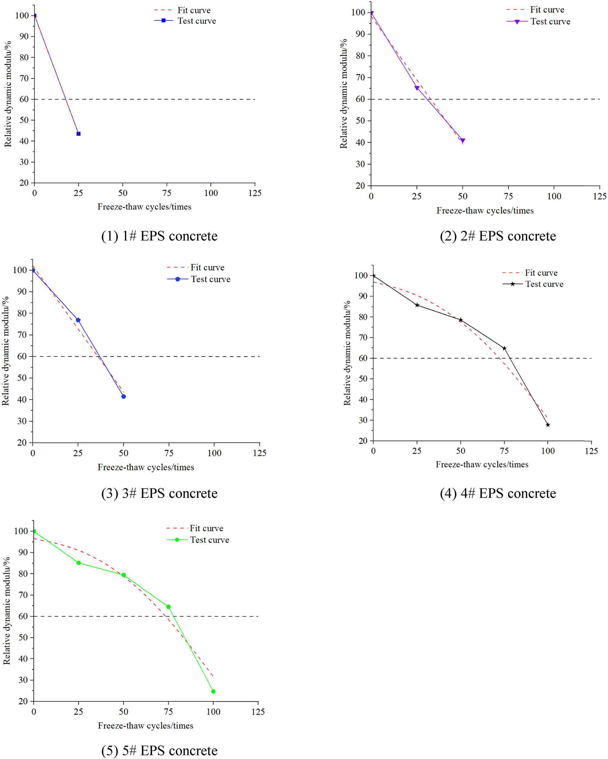
Relative dynamic elastic modulus fitting curve. (1) 1# EPS concrete. (2) 2# EPS concrete. (3) 3# EPS concrete. (4) 4# EPS concrete. (5) 5# EPS concrete.
Parameters of relative dynamic elastic modulus fitting curve
| Group | a | b | c |
|
|---|---|---|---|---|
| 1# | 0 | −2.26091 | 100.00000 | 100.00000 |
| 2# | 0 | −1.17602 | 98.27311 | 0.98976 |
| 3# | 0 | −1.17031 | 102.06430 | 0.98529 |
| 4# | −0.00599 | −0.06255 | 97.01008 | 0.96968 |
| 5# | −0.00643 | −0.00679 | 96.56239 | 0.96497 |
According to Yuan et al. [15], the damage rate can be calculated as −(2aN + b). When n is 0, 25, 50, 75, and 100 freeze–thaw cycles, the damage rates of each group of specimens after different cycles are calculated. As tabulated in Table 5, Group 1 had the largest damage rate, Groups 2 and 3 shared similar damage rates, and Groups 4 and 5 exhibited the smallest damage rates. The frost resistance of EPS concrete with added microbeads is significantly improved from the freeze–thaw damage rate.
Freeze–thaw damage rate
| Freeze–thaw cycles/times | Freeze–thaw damage rate | ||||
|---|---|---|---|---|---|
| 1# | 2# | 3# | 4# | 5# | |
| 0 | 2.26091 | 1.17602 | 1.17031 | 0.06255 | 0.00679 |
| 25 | 2.26091 | 1.17602 | 1.17031 | 0.36205 | 0.32829 |
| 50 | — | 1.17602 | 1.17031 | 0.66155 | 0.64979 |
| 75 | — | — | 1.17031 | 0.96105 | 0.97129 |
| 100 | — | — | — | 1.26055 | 1.29279 |
5 Conclusion
By studying the frost resistance of EPS concrete with different microbead dosages at the same density level, the following conclusions were drawn:
The addition of microbeads in EPS concrete significantly improves the frost resistance of EPS concrete, increasing its level by 10–60 magnitudes compared to concrete without microbeads; the improvement range is 66–400%. The improved frost resistance of EPS concrete has expanded its range of applications.
Adding microbeads can enhance the strength of EPS concrete. The strength of EPS concrete increased by 38–53% after the addition of microbeads, and the strength loss rate after freeze–thaw damage decreased by 8.1%.
The ITZ width and crack width of EPS concrete with added microbeads after freeze–thaw damage are significantly smaller than those of EPS concrete without microbeads; the hydration reaction is also more complete, it is mainly attributed to the smaller particle size of microbeads, which exhibits a better filling effect.
The calculated values from the EPS concrete freeze–thaw damage model agree well with the measured values. The damage characteristics predicted by the fitting model align with the actual freeze–thaw damage observed in the specimens. The damage model can well reflect the freeze–thaw damage law of EPS concrete.
The optimal microbead dosage is 15% of the cementitious material. At this dosage, the EPS concrete achieves optimal frost resistance and cost-effectiveness
-
Funding information: This research was funded by the “Pioneer” and “Leading Goose” R&D Program of Zhejiang (2023C03135), Science and technology project of the Ministry of Housing and Urban-Rural Development (2021-K-125), Taizhou science and technology project (22gyb07, 23gyb03), Science and technology project of Department of housing and urban-rural development of Zhejiang Province (2023K217, 2023K165, 2021K042).
-
Conflict of interest: Authors state no conflict of interest.
-
Data availability statement: All data included in this study are available upon request by contact with the corresponding author.
References
[1] Prasittisopin L, Termkhajornkit P, Kim YH. Review of concrete with expanded polystyrene (EPS): Performance and environmental aspects. J Clean Prod. 2022;366:1–21.10.1016/j.jclepro.2022.132919Search in Google Scholar
[2] Zhang WH, Lv YJ, Liu PY. Review on the research progress of EPS concrete. Mater Rep. 2019;33(7):2214–28.Search in Google Scholar
[3] Dissanayake DMKW, Jayasinghe C, Jayasinghe MTR. A comparative embodied energy analysis of a house with recycled expanded polystyrene (EPS) based foam concrete wall panels. Energy Build. 2017;135:85–94.10.1016/j.enbuild.2016.11.044Search in Google Scholar
[4] Mohammed HJ, Zain M. Experimental application of EPS concrete in the new prototype design of the concrete barrier. Constr Build Mater. 2016;124:312–42.10.1016/j.conbuildmat.2016.07.105Search in Google Scholar
[5] Meddage DPP, Chadee A, Jayasinghe MTR, Rathnayake U. Exploring the applicability of expanded polystyrene (EPS) based concrete panels as roof slab insulation in the tropics. Case Stud Constr Mater. 2022;17:1–16.10.1016/j.cscm.2022.e01361Search in Google Scholar
[6] Fernando PLN, Jayasinghe C, Jayasinghe MTR. Structural feasibility of Expanded Polystyrene (EPS) based lightweight concrete sandwich wall panels. Constr Build Mater. 2017;139:45–5.10.1016/j.conbuildmat.2017.02.027Search in Google Scholar
[7] Babu KG, Babu DS. Behaviour of lightweight expanded polystyrene concrete containing silica fume. Cem Concr Res. 2003;33(5):755–62.10.1016/S0008-8846(02)01055-4Search in Google Scholar
[8] Ferr´andiz F, García E. Physical and mechanical characterization of Portland cement mortars made with expanded polystyrene particles addition (EPS). Mater Constr. 2012;62:547–66.10.3989/mc.2012.04611Search in Google Scholar
[9] Dixit A, Pang SD, Kang SH, Moon J. Lightweight structural cement composites with expanded polystyrene (EPS) for enhanced thermal insulation. Cem Concr Compos. 2019;102:185–97.10.1016/j.cemconcomp.2019.04.023Search in Google Scholar
[10] JGJ383 JGJ383-2016. Technical specification of lightweight steel and lightweight concrete structures. Beijing: Ministry of Construction of the People’s Republic of China; 2016 (in Chinese).Search in Google Scholar
[11] Yuan J, Li W, Wang L, Wang J, Yang H, Zhang W. Study on carbonation resistance of EPS concrete based on mix proportion design. 2021 7th International Conference on Hydraulic and Civil Engineering & Smart Water Conservancy and Intelligent Disaster Reduction Forum (ICHCE & SWIDR). Nanjin, China: IEEE; 2021.10.1109/ICHCESWIDR54323.2021.9656423Search in Google Scholar
[12] Yuan J, Wang L, Li W, Yang H, Wang J, Zhang W, et al. A new EPS beads strengthening technology and its influences on axial compressive properties of concrete. Sci Eng Composite Mater. 2022;29:1–15.10.1515/secm-2022-0005Search in Google Scholar
[13] Yuan J, Li W, Wang L, Wang J, Yang H, Zhang W, et al. Experimental study on surface wrapping strengthening of EPS particles and its concrete performance. Sci Eng Composite Mater. 2022;29:23–6.10.1515/secm-2022-0002Search in Google Scholar
[14] Yuan J. Study on design, preparation and properties of EPS concrete based on modified foam particles. Beijing: University of Science and Technology Beijing; 2022.Search in Google Scholar
[15] Yuan J, Li D, Li W, Yang H, Zhang W, Wang L, et al. Study on frost resistance of EPS concrete based on EPS beads wrapping modification. Constr Build Mater. 2022;345(22):1–17.10.1016/j.conbuildmat.2022.128400Search in Google Scholar
[16] Wang YX. Study on the application of lightweight steel and lightweight concrete structures in small island resort buildings. Guang Zhou: South China University of Technology; 2017.Search in Google Scholar
[17] Mehta PK. Durability of concrete-fifty years of progress? Montreal: Proceedings of the 2nd International Conference on Durability of Concrete; 1991. p. 1–32.Search in Google Scholar
[18] Guo L. Study on energy absorption characteristics and frost resistance of foam concrete and EPS concrete. Harbin: Northeast Forestry University; 2019.Search in Google Scholar
[19] Guan H. The effect of waterproof coating on frost resistance of EPS concrete. J Heilongjiang Inst Technol. 2017;31(1):5–8.Search in Google Scholar
[20] Hu GF. Research on preparation and performance of high specific strength EPS lightweight concrete. Kai fen: Henan University; 2020.Search in Google Scholar
[21] Cao D. Enhanced buckling strength of the thin‑walled continuous carbon fiber–reinforced thermoplastic composite through dual coaxial nozzles material extrusion process. Int J Adv Manuf Technol. 2023;128:1305–15.10.1007/s00170-023-12014-8Search in Google Scholar
[22] Cao D. Strengthening the interphase of thermoplastic sandwich composites by interleaving carbon nanotube yarns. Mater Today Commun. 2023;36:106655.10.1016/j.mtcomm.2023.106655Search in Google Scholar
[23] Cao D, Bouzolin D, Lu H. Bending and shear improvements in 3D-printed core sandwich composites through modification of resin uptake in the skin/core interphase region. Compos Part B. 2023;264:110912.10.1016/j.compositesb.2023.110912Search in Google Scholar
[24] Akhtar M, Khajuria A. The synergistic effects of boron and impression creep testing during paced controlling of temperature for P91 steels. Adv Eng Mater. 2023;25:2300053.10.1002/adem.202300053Search in Google Scholar
[25] Akhtar M, Khajuria A, Sahu JK, Swaminathan J, Kumar R, Bedi R, et al. Phase transformations and numerical modelling in simulated HAZ of nanostructured P91B steel for high temperature applications. Appl Nanosci. 2018;25:2300053–1685.10.1007/s13204-018-0854-1Search in Google Scholar
[26] Feng NQ, Li H. Characteristics and applications of nanobeads. China Concr Cem Products. 2010;(5):1–3.Search in Google Scholar
[27] GB 8076–2008. Concrete admixtures. Beijing: General Administration of Quality Supervision, Inspection and Quarantine of the People’s Republic of China/Standardization Administration of the People’s Republic of China; 2009.Search in Google Scholar
[28] GB/T 1596-2017. Fly ash used for cement and concrete. Beijing: The General Administration of Quality Supervision, Inspection and Quarantine of the People’s Republic of China/China National Standardization Administration; 2018 (in Chinese).Search in Google Scholar
[29] GB/T50081-2009. Standard for test methods of concrete physical and mechanical properties. Beijing: China Architecture and Building Press; 2009 (in Chinese).Search in Google Scholar
[30] GB/T50082-2009. Standard for test methods of long-term performance and durability of ordinary concrete. Beijing: China Architecture and Building Press; 2009 (in Chinese).Search in Google Scholar
[31] JGJ51-2002. Technical specification for lightweight aggregate concrete. Beijing: Ministry of Construction of the People’s Republic of China; 2003.Search in Google Scholar
[32] Zhang HM, Wang D, Jing PY. Freeze-thaw damage characteristics of aeolian sand concrete with different replacement ratios. J Henan Univ Sci Technology(Natural Sci). 2023;44(3):70–7.Search in Google Scholar
[33] Wang HG. Drying shrinkage and cabronation of pavement concrete with nano-particles. Harbing: Northeast Forestry University; 2012.Search in Google Scholar
[34] Zhang MH. Life-cycle performance of nano-pavement concrete. Harbing: Harbing Institute of Technology; 2007.Search in Google Scholar
[35] Liu WD, Su WT, Wang YM. Research on damage model of fibre concrete under action of freeze-thaw cycle. J Build Struct. 2008;29(1):124–8.Search in Google Scholar
[36] Wang C, Zhou Y, Wang G, Liu T, Wang X, Cao F. Microstructure and damage evolution model of steel slag fine aggregates concrete under freezing-thawing environment. Chin J Appl Mech. 2023;61(4):1000–4939.Search in Google Scholar
[37] Ji XD, Song YP, Liu J. Study on frost damage constitutive model of concrete. Chin J Comput Mech. 2011;28(3):461–7.Search in Google Scholar
[38] Zhu CH, Liu X, Wu Y, Liu Q. Study of freeze-thaw durability and damage model of hybrid fiber concrete. Ind Constr. 2015;45(2):10–4.Search in Google Scholar
[39] Zhao Y, Fan X, Wang L, Shi J. Attenuation model of mechanical properties of concrete under different freezing and thawing. Acta Mater Compos Sin. 2017;34(2):463–70.Search in Google Scholar
© 2024 the author(s), published by De Gruyter
This work is licensed under the Creative Commons Attribution 4.0 International License.
Articles in the same Issue
- Regular Articles
- Research on damage evolution mechanisms under compressive and tensile tests of plain weave SiCf/SiC composites using in situ X-ray CT
- Structural optimization of trays in bolt support systems
- Continuum percolation of the realistic nonuniform ITZs in 3D polyphase concrete systems involving the aggregate shape and size differentiation
- Multiscale water diffusivity prediction of plain woven composites considering void defects
- The application of epoxy resin polymers by laser induction technologies
- Analysis of water absorption on the efficiency of bonded composite repair of aluminum alloy panels
- Experimental research on bonding mechanical performance of the interface between cementitious layers
- A study on the effect of microspheres on the freeze–thaw resistance of EPS concrete
- Influence of Ti2SnC content on arc erosion resistance in Ag–Ti2SnC composites
- Cement-based composites with ZIF-8@TiO2-coated activated carbon fiber for efficient removal of formaldehyde
- Microstructure and chloride transport of aeolian sand concrete under long-term natural immersion
- Simulation study on basic road performance and modification mechanism of red mud modified asphalt mixture
- Extraction and characterization of nano-silica particles to enhance mechanical properties of general-purpose unsaturated polyester resin
- Roles of corn starch and gellan gum in changing of unconfined compressive strength of Shanghai alluvial clay
- A review on innovative approaches to expansive soil stabilization: Focussing on EPS beads, sand, and jute
- Experimental investigation of the performances of thick CFRP, GFRP, and KFRP composite plates under ballistic impact
- Preparation and characterization of titanium gypsum artificial aggregate
- Characteristics of bulletproof plate made from silkworm cocoon waste: Hybrid silkworm cocoon waste-reinforced epoxy/UHMWPE composite
- Experimental research on influence of curing environment on mechanical properties of coal gangue cementation
- Multi-objective optimization of machining variables for wire-EDM of LM6/fly ash composite materials using grey relational analysis
- Synthesis and characterization of Ag@Ni co-axial nanocables and their fluorescent and catalytic properties
- Beneficial effect of 4% Ta addition on the corrosion mitigation of Ti–12% Zr alloy after different immersion times in 3.5% NaCl solutions
- Study on electrical conductive mechanism of mayenite derivative C12A7:C
- Fast prediction of concrete equivalent modulus based on the random aggregate model and image quadtree SBFEM
- Research on uniaxial compression performance and constitutive relationship of RBP-UHPC after high temperature
- Experimental analysis of frost resistance and failure models in engineered cementitious composites with the integration of Yellow River sand
- Influence of tin additions on the corrosion passivation of TiZrTa alloy in sodium chloride solutions
- Microstructure and finite element analysis of Mo2C-diamond/Cu composites by spark plasma sintering
- Low-velocity impact response optimization of the foam-cored sandwich panels with CFRP skins for electric aircraft fuselage skin application
- Research on the carbonation resistance and improvement technology of fully recycled aggregate concrete
- Study on the basic properties of iron tailings powder-desulfurization ash mine filling cementitious material
- Preparation and mechanical properties of the 2.5D carbon glass hybrid woven composite materials
- Improvement on interfacial properties of CuW and CuCr bimetallic materials with high-entropy alloy interlayers via infiltration method
- Investigation properties of ultra-high performance concrete incorporating pond ash
- Effects of binder paste-to-aggregate ratio and polypropylene fiber content on the performance of high-flowability steel fiber-reinforced concrete for slab/deck overlays
- Interfacial bonding characteristics of multi-walled carbon nanotube/ultralight foamed concrete
- Classification of damping properties of fabric-reinforced flat beam-like specimens by a degree of ondulation implying a mesomechanic kinematic
- Influence of mica paper surface modification on the water resistance of mica paper/organic silicone resin composites
- Impact of cooling methods on the corrosion behavior of AA6063 aluminum alloy in a chloride solution
- Wear mechanism analysis of internal chip removal drill for CFRP drilling
- Investigation on acoustic properties of metal hollow sphere A356 aluminum matrix composites
- Uniaxial compression stress–strain relationship of fully aeolian sand concrete at low temperatures
- Experimental study on the influence of aggregate morphology on concrete interfacial properties
- Intelligent sportswear design: Innovative applications based on conjugated nanomaterials
- Research on the equivalent stretching mechanical properties of Nomex honeycomb core considering the effect of resin coating
- Numerical analysis and experimental research on the vibration performance of concrete vibration table in PC components
- Assessment of mechanical and biological properties of Ti–31Nb–7.7Zr alloy for spinal surgery implant
- Theoretical research on load distribution of composite pre-tightened teeth connections embedded with soft layers
- Coupling design features of material surface treatment for ceramic products based on ResNet
- Optimizing superelastic shape-memory alloy fibers for enhancing the pullout performance in engineered cementitious composites
- Multi-scale finite element simulation of needle-punched quartz fiber reinforced composites
- Thermo-mechanical coupling behavior of needle-punched carbon/carbon composites
- Influence of composite material laying parameters on the load-carrying capacity of type IV hydrogen storage vessel
- Review Articles
- Effect of carbon nanotubes on mechanical properties of aluminum matrix composites: A review
- On in-house developed feedstock filament of polymer and polymeric composites and their recycling process – A comprehensive review
- Research progress on freeze–thaw constitutive model of concrete based on damage mechanics
- A bibliometric and content analysis of research trends in paver blocks: Mapping the scientific landscape
- Bibliometric analysis of stone column research trends: A Web of Science perspective