Research on damage evolution mechanisms under compressive and tensile tests of plain weave SiCf/SiC composites using in situ X-ray CT
-
Jiangxing Wu
 and
Lijuan Sun
and
Lijuan Sun

Abstract
To investigate the damage evolution and failure mechanisms of fiber-reinforced composite materials under complex conditions, this study conducted in situ X-ray computed tomography (CT) compression and tensile tests on plain weave two-dimensional woven SiC/SiC composite materials. The obtained CT in situ image data captured the behavior of materials during loading and after failure. Using the image reconstruction of CT data, the actual microstructure and damage evolution of the material under six consecutive loading levels were accurately revealed. Three-dimensional visualization models of the composite material were established using image processing software to analyze the damage evolution under compression and tension, and the failure mechanisms were compared. The results showed that the compression and tension failure mechanisms of SiC/SiC composite materials were similar, with the transverse cracking of the matrix being the first mode of damage, followed by delamination between layers and longitudinal matrix cracking of fiber bundles. Specifically, in terms of compression failure, the strength of the fiber bundle itself has a greater influence, and fiber fracture is the main cause of ultimate material failure. On the other hand, the primary cause of tensile failure is the presence of porosity defects generated during material fabrication. Consequently, the tensile material fails earlier and can withstand lower loads.
1 Introduction
Composite materials have been widely applied in various advanced engineering fields in recent years [1,2,3], with lightweight and high-performance ceramic composites becoming a hot topic of research, particularly in areas such as aviation, aerospace, and atomic energy. Within this field, continuous fiber-reinforced SiC/SiC composites have received great attention due to their exceptional properties such as high temperature and corrosion resistance, high strength and toughness, and oxidation resistance [4]. They offer significant potential for use in critical components that operate in high-temperature environments [5] and an ideal material choice for high-thrust-to-weight ratio aerospace engines, rocket engines, and crucial components of nuclear reactors operating at high temperatures.
Due to the influence of the preparation process, ceramic matrix composites (CMCs) often contain initial defects such as microcracks, uneven matrix deposition resulting in micropores, and thermal damage. These defects make the material susceptible to damage modes such as matrix cracking, delamination, fiber pull-out, and fracture when subjected to loads, resulting in nonlinear mechanical behavior of the material. Similar to other CMCs, the damage initiation and crack formation in SiC/SiC composite materials are typically associated with stress concentrations around sharp edges of internal voids. Due to the multi-scale nature of the microstructure, voids are generally classified into two categories: micropores within fiber bundles and macropores between fiber bundles [6].
Damage evolution analysis of composite materials is a recognized challenge and is the basis for studying the mechanical performance of materials [7,8]. Traditional research on CMCs mainly relies on static tests supplemented by characterization tools such as optical microscopes and electron microscopes [9,10]. This method can only obtain the macroscopic mechanical properties [11,12,13] and the surface microstructure [14,15] of the material. For instance, Chen and Liu [16] investigated the typical damage and failure modes of two-dimensional (2D) woven SiC/SiC compression specimens. Cao et al. [17] compared the compression failure mechanisms of SiC/SiC composite materials fabricated using two different methods. Li et al. [18] discussed the fracture mechanisms of ring-shaped SiC/SiC composite materials under compressive loading. Wang et al. [19] studied the fracture behavior of 2D SiC/SiC composite materials under uniaxial quasi-static and dynamic compression loads. These failure analyses in these studies were conducted post-failure, providing limited information on the damage evolution related to the microstructure [20,21], and cannot determine when the material initiates failure.
Maillet et al. [22] combined in situ synchrotron X-ray microtomography and acoustic emission to study the behavior of CMC laminates subjected to in-plane tensile or bending loads at ambient temperature. They characterized the initiation and progression of matrix cracking and fiber fracture using microtomography imaging. Chateau et al. [23] performed in situ X-ray microtomography tensile tests to characterize the propagation of matrix cracks and occurrence of fiber fractures in SiC/SiC microcomposites. Li et al. [24] proposed a novel in situ experimental method for non-destructive observation of the failure process of three-dimensional (3D) woven carbon fiber-reinforced composite materials. Wan et al. [25] observed the in situ damage development within 3D C/C-SiC ceramic composite materials as compressive loads were applied longitudinally, transversely, and obliquely to their anisotropic structure. Zeng et al. [26] designed in situ shear tests using computed tomography (CT) to obtain u-CT images of plain weave composites. These images were then used to characterize the damage evolution of the composite material under in situ shear experiments. Bale et al. [27,28] observed the damage evolution of single-directional SiC/SiC fiber bundles under various levels of loading based on in situ X-ray CT tests. Chen et al. [29] observed the displacement field and strain field changes of CMCs by conducting X-ray CT in situ uniaxial and biaxial tensile tests. Guo et al. [30] performed compressive tests on SiC fiber-reinforced SiC matrix composites using in situ X-ray CT. Using the image reconstruction of CT data, the microstructure and damage evolution of the material under continuous loading were accurately revealed.
As mentioned earlier, it can be seen that researchers have carried out extensive research on the analysis of the two types of loading damage in the vertical direction of CMCs. However, these experiments often only examine the damage evolution of materials under a single loading condition, which is insufficient when considering the daily operating conditions of SiC/SiC composite materials.
Therefore, in this study, micro-X-ray CT in situ tensile and compressive tests were conducted on 2D plain-woven SiC/SiC composite materials to investigate the initial microstructure and the evolution of tensile and compressive damage. Subsequently, the Avizo algorithm was applied to the recorded 2D and 3D images to extract pores and cracks, revealing the process of damage evolution in the composite material. Finally, scanning electron microscopy (SEM) was used to examine the fractured surfaces at the microscale to further elucidate the failure mechanisms.
2 Experimental
2.1 SiC/SiC composite specimens
The specimens were made of 2D plain-weave laminated SiC/SiC composite materials prepared using the chemical vapor infiltration (CVI) process, with the toughening phase consisting of third-generation SiC fibers, about 500 fibers per bundle and with a single fiber diameter of 12.6
2.2 In situ X-ray compressive and tensile tests
The in situ X-ray compression and tensile tests were conducted at the State Key Laboratory for Nonlinear Mechanics of the Institute of Mechanics, Chinese Academy of Sciences. In situ loading experiments were conducted using the BL13HB beamline of the Shanghai Synchrotron Radiation Facility, equipped with an in situ loading apparatus. This apparatus allowed for the acquisition of images depicting the internal damage evolution of the material during room temperature loading (Figure 1). The in situ loading test equipment used was the Y. CT Modular system from Yxlon, Germany. After each loading, a pause of approximately 20 min was needed to collect fracture images at the relevant stress levels. In the compressive tests, five loading cycles were performed until final fracture. During compression, the compression force was halted to scan the specimen at load levels of 339.037, 747.593, 1358.280, 1919.379, and 2298.296 N. The compression force was sequentially loaded to these levels. During the tensile test, the tensile force was halted to scan the specimen at load levels of 135.828, 230.692, and 351.428 N. A total of three loading cycles were performed, with the tensile force being sequentially loaded to these levels. Due to the requirement for sample size, a voxel size of 9

Experimental setup of SR-CT equipment.
3 Microstructural analysis of the initial sample
The Pitre3 software was used to obtain the sliced morphology of the composite material, and the reconstructed images were further processed and visualized using Avizo software for observation and analysis. The Avizo software was used to perform 3D reconstruction of CT scan slices of SiC/SiC composite material for the purpose of observing its initial microstructure. Due to the laminar structure of SiC/SiC composites and the CVI process used, defects such as porosity can occur in the material. This can be observed from Figure 2(a), where it is evident that the original morphology of the compressed and stretched samples contains various shaped pore defects before loading.
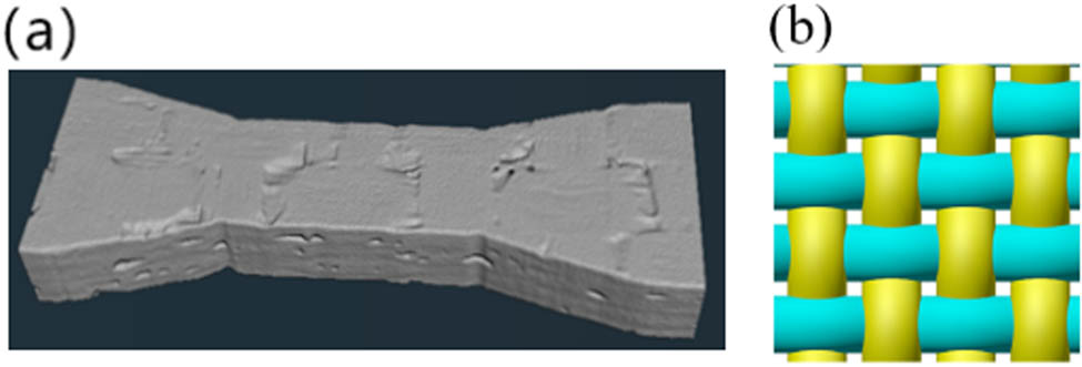
(a) 3D reconstructed CT image of SiC/SiC composite material test specimen and (b) plain weave structure.
Pores are one of the primary defects in SiC/SiC composite materials, which have a negative impact on mechanical properties such as compressive strength and tensile properties. The structure of a plain weave is illustrated in Figure 2. In the plain weave structure, two longitudinal fiber bundles interweave with two transverse fiber bundles in one cycle. However, there are no fiber bundles in the middle to cover the non-overlapping area, resulting in the formation of pores.
The internal pores of the material can be divided into initial pores generated during the preparation process and cracks caused by external loading. According to the volume of pore structures, pores can be divided into two categories: one mainly distributed between adjacent fibers inside the fiber bundle, with a small volume, referred to as micropores within the fiber bundle; the other mainly exists between neighboring fiber bundles, with a large volume, called large voids outside the fiber bundle, as shown in Figure 3. The longitudinal distribution of micropores along the fiber bundle is determined by the microstructural characteristics of the fiber bundle itself. Although the pore volume is small, the number of micropores is high and there is almost no connection between them. The larger voids mainly distribute in the non-overlapping regions of each layer of warp and weft yarns. During the CVI manufacturing process, overlapping fiber yarns can provide much larger surface area than non-overlapping regions, and the matrix can rapidly deposit into the fiber yarns. However, as the deposition process proceeds, the matrix deposits slowly in the non-overlapping region and gas residue at non-overlapping regions forms large voids as the transport channels of reaction gases gradually close. In summary, the distribution of micropores and large voids is irregular, but their positional features are apparent. Large voids mainly distribute in non-overlapping regions, while micropores are distributed inside the fiber bundle.
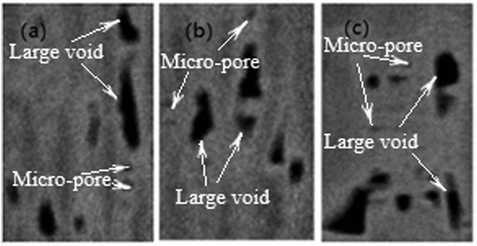
(a) Slice in the xOy plane, (b) slice in the yOz plane, and (c) slice in the xOz plane.
4 Test result analysis
4.1 Compressive test result analysis
4.1.1 Load–displacement curve
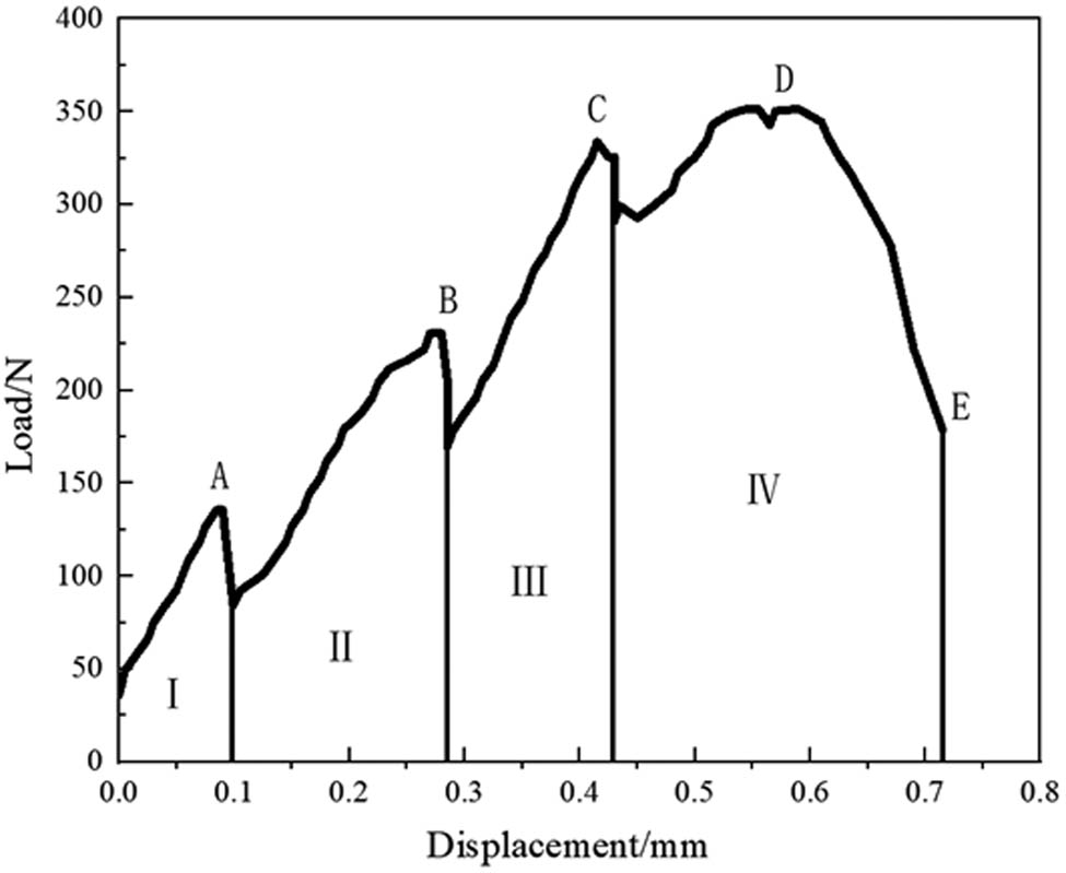
The load–displacement response of a material during loading is a macroscopic characterization of its internal damage evolution process. Figure 4 shows the load–displacement curve of the compressed specimen under continuous loading. The first stage of the curve is relatively gentle, showing linear changes, and the elastic modulus is constant, indicating that the material has almost no damage. In the second stage, AB segment, the curve enters the nonlinear stage, which may be due to the gradual damage inside the material and the propagation of cracks from the matrix to the fibers and between fiber plies. The deformation of the specimen increases linearly with the increase of compression load. In the third stage, BD segment, the curve enters a linear stage, and the deformation of the specimen increases linearly with the increase of compression load. In the fourth stage, in the later stage of DE, as the compression load increases, the slope of the curve slightly decreases, and it drops significantly when approaching the ultimate load, indicating that the material has damage during this process; subsequently, when the load reached its ultimate state, the fiber bundle fractured and the test specimen failed by compressive cracking.
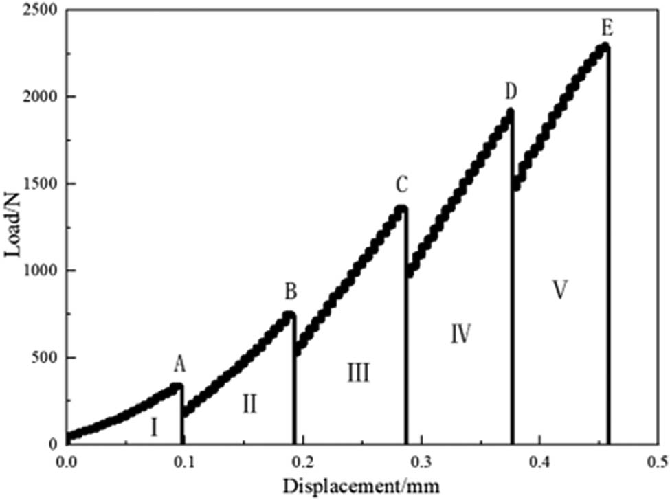
Load–displacement curve of compressive tests.
In addition, the entire evolution of the load–displacement curve of the specimen shows brittle fracture characteristics [31,32]. This is because the matrix mainly bears the load during compression, so the load increases slowly with the increase of load. A displacement occurs in the elastic deformation stage, and the material has a low elastic modulus when compressing parallelly. Once the ultimate load that the matrix can bear is exceeded, the matrix will fracture or crush, causing a sharp drop in the curve, leading to the failure of the material.
4.1.2 Evolution process of compression damage
In this study, the 3D reconstructed CT data of the SiC/SiC composite material under four loading states – 339.031, 747.593, 1358.28, and 2290.221 N – were selected to visualize and analyze the microstructural morphology of the material. Using the AVIZO software, the internal pore distribution, crack initiation, size changes, and other damage information of the material during the compression process were observed.
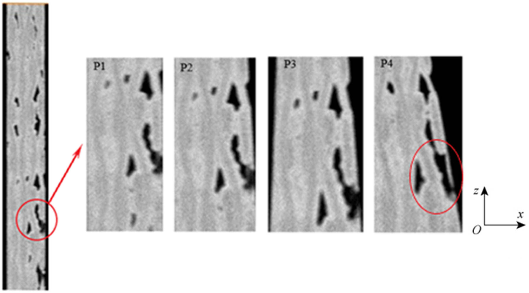
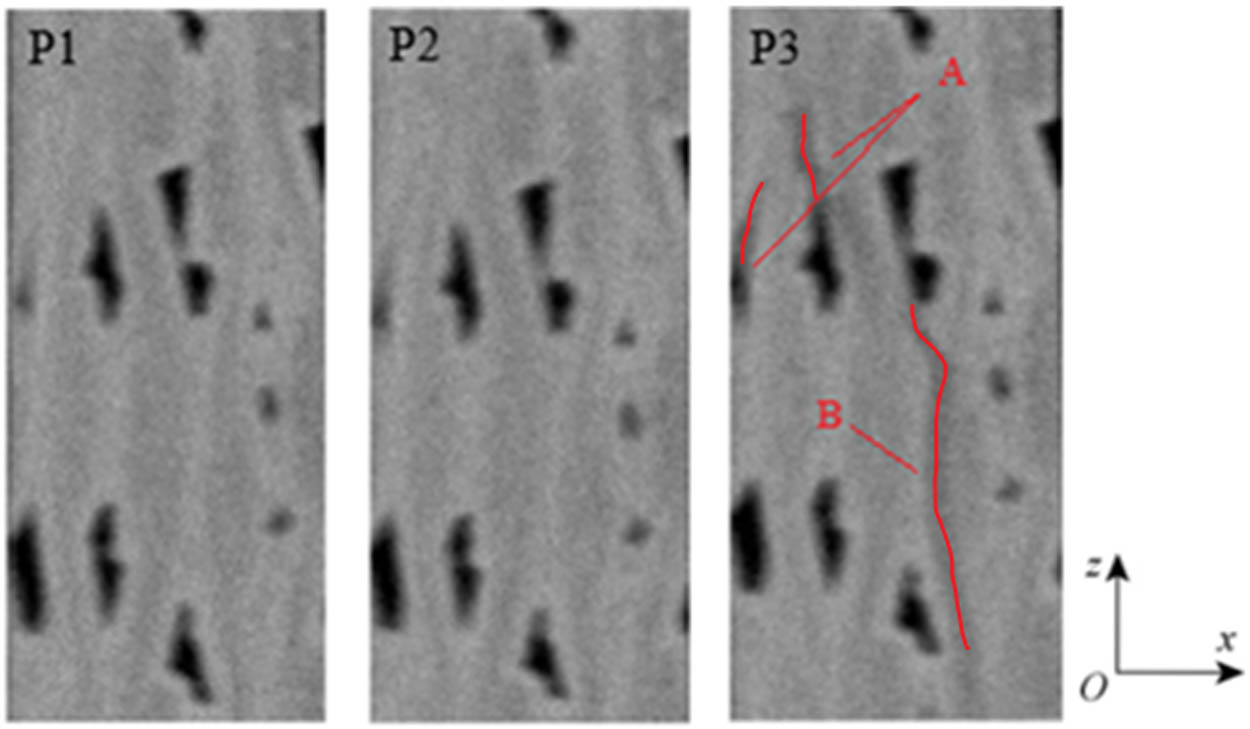
Using the internal CT imaging technique perpendicular to the three coordinate axes, the internal damage process of SiC/SiC composite material during compression was investigated. Figure 5 shows a set of local CT 2D sections of the xOy cross-section of the test piece. It can be seen that for the first loading, P1 section shows no significant changes. During the second loading, the local pores showed a contraction trend as shown in P2. After the third loading, the previously circled pores had disappeared, causing the pore to split into two ends labeled A and B. Simultaneously, three pore regions beneath the figures experience compression. The pore volume in the central red circle decreases, while the pore in the lower-right corner, being located near the boundary, is influenced by the compressive damage to the outer surface of the matrix, resulting in an increase in volume and the formation of cracks extending outward. After the fifth loading, cracks at positions A and B originated from the pore, extending in a direction almost parallel to the weft fiber bundle, with the crack end at position C penetrating through the fiber bundle from A to B. The crack at position B extended to the edge of the specimen, eventually resulting in the fracture of warp fiber bundles and the formation of matrix cracks between two layers, causing interlayer cracking and separating the fiber bundles between the left and right matrix.
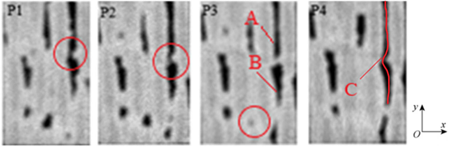
Evolution process of damage in the xOy plane.
Figure 6 displays a set of local CT 2D sectional diagrams on the xOz cross-section of the test piece. As indicated in the figure, the specimen initially had a defect with a large hole that extended to the sample’s surface. In the initial loading process (P1), there was only a minor change observed at this location. However, by the third loading stage, as depicted in the P3 diagram, it becomes apparent that the defect had expanded and transformed into an inclined crack oriented toward the compressive direction. This crack was a longitudinal crack within the fiber bundle, originating from the specimen’s edge and propagating inside. Under the fifth loading condition, the specimen was crushed, and the P4 diagram showed obvious interlayer cracking in the matrix between two adjacent fiber bundles. The cracking started from the hole and was almost parallel to the nearby fiber bundles.
Evolution process of local area damage in the xOz plane.
Figure 7 presents a group of local CT cross-sections on the yOz plane of the specimen. No damage was observed in the fiber matrix under the two loading conditions shown at P1 and P2. Under the third loading condition shown at P3, there was a trend of shrinkage in local pores. At the fifth loading condition shown at P4, transverse cracks perpendicular to the compression direction were discovered within the circle. At the same time, cracks occurred at location A at the boundary of the fiber bundle overlap, which belonged to the matrix cracks within the fiber bundle. The crack indicated by arrow B is the transverse crack in the matrix outside the warp fiber bundle. At this point, the specimen was partially crushed and the hole at the fiber bundle fracture enlarged.
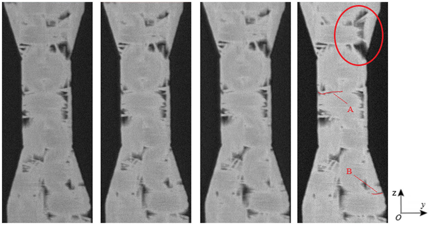
Evolution process of local area damage in the yOz plane.
4.2 Tensile test result analysis
4.2.1 Load–displacement curve
Figure 8 shows the load–displacement curve for continuous horizontal tension loading. In the first stage, the curve is relatively flat and shows linear change, with a constant elastic modulus, indicating that the material has suffered almost no damage. During the second stage, AB, the curve shows a non-linear variation, and the slope decreases in the latter half. This indicates the occurrence of internal damage within the material, which continues to develop. In the third stage, section BC of the curve enters the linear phase, and the deformation of the specimen increases linearly with the increase of compressive load. In the fourth stage, section CD of the curve displays a gradually decreasing slope with the continuous increase of load. This indicates that the matrix has failed, and the stress relief effect of the interface layer has reached saturation, and cracks are gradually starting to emerge and expand within the fibers. After reaching the peak load in the DE stage, the composite material still exhibits a certain level of load-bearing capacity. However, subsequently, the load-bearing capacity of the composite material is completely lost, leading to the final rupture of the specimen.
Load–displacement curve of tensile tests.
4.2.2 Evolution of tensile damage
To visualize and analyze the microscopic structure of the material during the tensile test, the 3D reconstructed CT data of the material under three different loadings (135.828, 230.692, and 351.428 N) were selected. AVIZO 9.1 software was used to observe the distribution of internal pores, crack initiation, and size changes during the tensile damage process. Internal damage to the SiC/SiC composite material was also observed through cross-sectional imaging perpendicular to the three coordinate axes during the compression process.
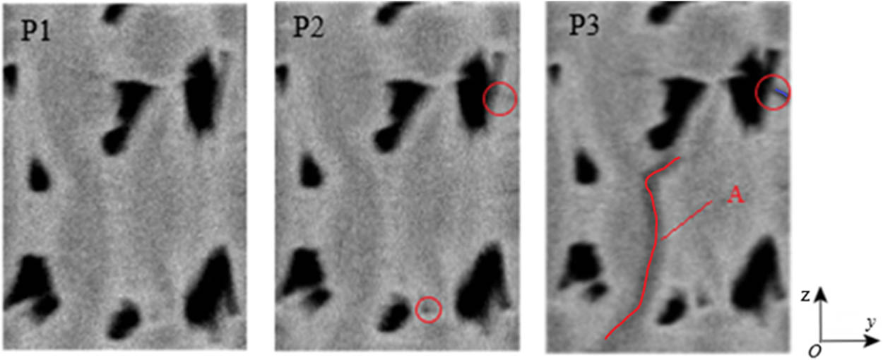
Figure 9 shows a set of CT 2D sectional diagrams on the xOy cross-section of the test piece under three different loading conditions. Under the first loading condition P1, no damage or destruction was observed in the fiber matrix. Under the tensile load applied to P2, there is an observed tendency of micropores in the region indicated by A to expand, resulting in increased volume and the formation of defects. Under the loading condition of P3, transverse cracking occurs within the matrix of the warp fiber bundle indicated by B, perpendicular to the direction of tension. The crack propagates from the outside to the inside of the specimen and ultimately forms a matrix crack between two layers of fiber bundles, leading to delamination.
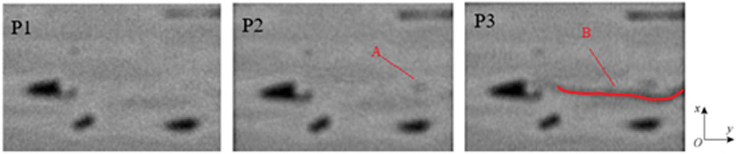
Evolution process of local area damage in the xOy plane.
Figure 10 shows a set of local CT 2D sectional diagrams on the xOz cross-section of the test piece. Under the first and second loading conditions (P1 and P2), no damage or destruction was observed in the fiber matrix. Under the loading condition of P3, as indicated by A, we can observe that the crack located at A starts from a large pore within the matrix and extends into the interior of the matrix, resulting in matrix cracking. The main cause of this is the presence of residual porosity defects from the fabrication process. The crack indicated by B was a longitudinal crack inside the fiber bundle, which extended from the edge of the specimen toward the interior. Obvious interlayer cracks occurred in the matrix between adjacent fiber bundles, and the cracks were parallel to the nearby fiber bundle direction. Finally, the specimen was pulled apart.
Evolution process of local area damage in the xOz plane.
Figure 11 shows a set of local CT 2D sectional diagrams on the yOz cross-section of the test piece. Under the first loading condition (P1), no damage or destruction was observed inside the fiber matrix. Under the loading condition of P2, it can be observed that the micropores expand and there is transverse cracking in the matrix. This crack is due to stress concentration during the tensile loading process, causing the larger pores near the edge of the specimen to extend toward the outer surface. Under the loading condition of P3, in the region indicated by A, there is a poor bond between the fiber bundles and the matrix, resulting in noticeable longitudinal cracks within the matrix between the two layers of fiber bundles. These interlaminar cracks are parallel to the nearby fiber bundle orientations and become more pronounced after the specimen is pulled apart.
Evolution process of local area damage in the yOz plane.
4.3 Fractographic analysis
Earlier, the evolution of compression and tension damage in plain weave SiC/SiC composite was discussed. In this section, fracture analysis of the tested specimens will be performed. The fracture surfaces of the specimens that underwent in situ compressive and tensile tests were observed using SEM. Figure 12 shows the SEM image of the compressive fracture surface, where it can be seen that almost all of the longitudinal fiber bundles are fractured at the fracture surface. The fracture mainly occurred at the fiber overlap boundary, with an irregular fracture surface and obvious fiber pull-out and interlaminar cracking phenomena. At the location where delamination was more severe, separation occurred between the matrix and upper-lower fiber bundles. Figure 13 shows the microstructure of the tensile fracture surface of the specimen, where it is evident that the longitudinal fibers are pulled out at different fracture locations with an uneven fracture surface. The transverse fiber bundles fractured, while interlaminar cracking was also apparent. Based on the SEM image, it can be generally observed that the length of fiber pull-out on the compression fracture surface is shorter than that on the tensile fracture surface. Additionally, the fracture surface tilts toward the fiber axis direction.
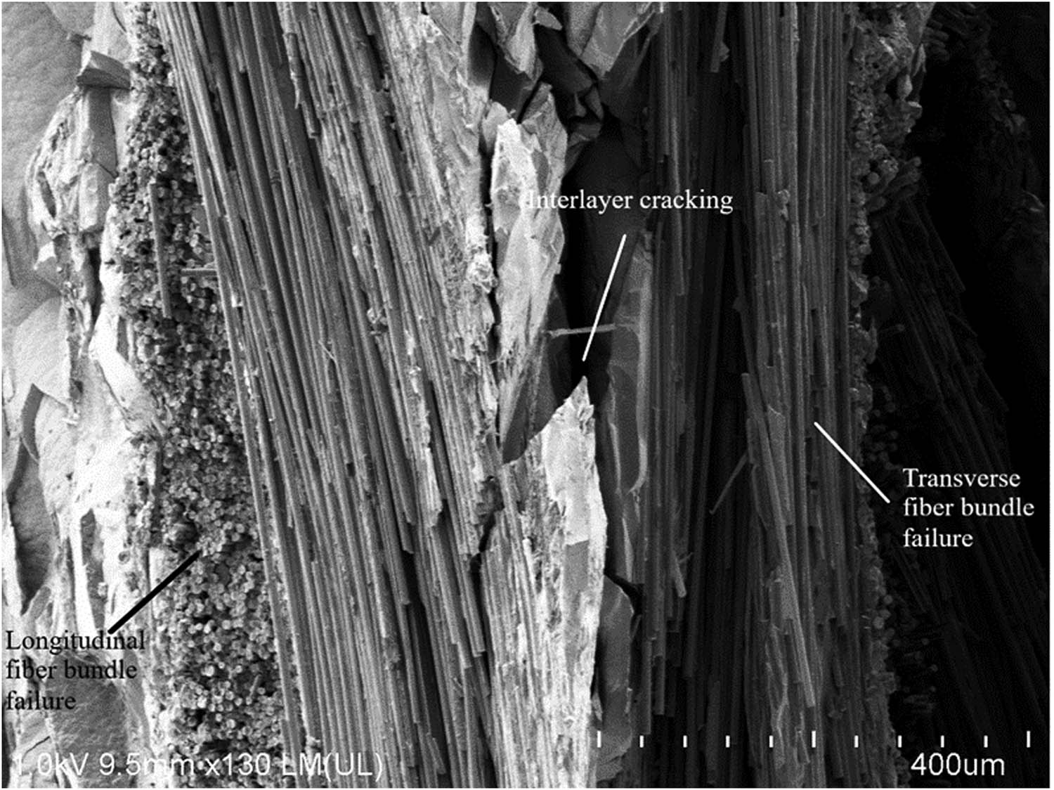
SEM image of the tensile compressive surface of the specimen.
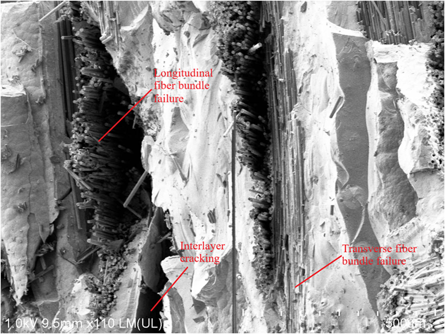
SEM image of the tensile fracture surface of the specimen.
5 Comparison of failure mechanisms of SiC/SiC composites under compression and tension
The damage evolution of SiC/SiC composites under compression and tension was analyzed using CT in situ tests. It was found that the failure mechanisms were quite similar, mainly including transverse cracking of the matrix, interlayer cracking, longitudinal cracking of fiber bundles, and fiber bundle fracture. The specific points are explained as follows:
5.1 Transverse cracking of the matrix
Due to the relatively small strain at which matrix failure occurs, transverse cracks perpendicular to the compression direction first appear in the compression process (Figure 5, P4). Similarly, in the tension process, transverse cracks perpendicular to the loading direction first occur in the matrix, which can be divided into two categories: transverse cracks outside fiber bundles (Figure 11, P2) and transverse cracks inside fiber bundles (Figure 9, P3). Both categories of cracks are perpendicular to the loading direction and are therefore referred to as transverse cracks of the matrix. The matrix cracks inside fiber bundles mainly occur in the weft direction, and many of them evolve from micropore within fiber bundles. Due to the relatively weak interface layer between fibers and matrix, these transverse cracks usually propagate along the interface. The matrix cracks outside fiber bundles mainly occur at the overlap boundary of fibers, near large voids in the matrix, and at the edge of the material. Due to the damage of voids, stress concentration develops, promoting the damage and cracking of the material.
5.2 Interlayer cracking
In the compressive loading test, interlayer cracking gradually occurred in the matrix between bundles with increasing load (Figure 5, P4). In the tensile test, with the increase of tension, interlayer cracking gradually appeared in the matrix between bundles (Figure 9, P3; Figure 10, P3; and Figure 11, P3). Interlayer cracking usually occurs at the edge of large voids and extends outward in the matrix between fiber bundles. Since interlayer cracks are generally parallel to the orientation of adjacent fiber bundles, they do not enter the fiber bundle interior during the process of crack propagation, but instead continue to extend within the matrix between fiber layers, causing delamination of the material. In areas where interlayer cracking is severe, the matrix between layers separates from the upper and lower fiber bundles.
5.3 Longitudinal cracking of fiber bundles
The occurrence of longitudinal cracks inside fiber bundles is more complex and rarer before material failure. The geometric characteristics, arrangement, and initial defects of fiber bundles make them susceptible to stress concentration, resulting in longitudinal cracks within the matrix in the yOz plane (Figure 7, P4) and in the xOz plane (Figure 10, P3). Transverse cracks in the outside matrix are mostly perpendicular to the nearby fiber bundle and are easy to enter the interior of the fiber bundle during the propagation process. Due to the relatively weak interface layer between fibers and matrix, the longitudinal cracks continue to propagate along the fiber direction within the matrix, where the plane of a longitudinal crack is parallel to the loading direction, making it difficult to close after releasing the load.
5.4 Fracture of fiber bundles
When the material reaches its ultimate strength, failure occurs due to the fracture of fiber bundles. The energy accumulated by the material under tensile load is suddenly released, resulting in severe separation between fiber bundles and matrix (Figure 5, P4; Figure 11, P3), and many interlayer cracks continue to propagate. After fracture, the cross-section of the material is uneven, and obvious fiber pull-out occurs, indicating that the material has good toughness. When the fiber is pulled out, the friction between the fiber and the matrix interface effectively absorbs the energy generated by the external load. Due to the release of the tensile stress inside the material, transverse cracks in the matrix shrink or close.
Through the analysis of failure mechanisms, it can be seen that the failure mechanisms of the materials are generally similar, but the specific forms of failure are different. Specifically, under compressive loading conditions, as the loading progresses, the pre-existing pores in the specimen are compressed, resulting in a reduction in pore volume and a decrease in porosity. Subsequently, with the increase in load, numerous cracks first appear in the outer coating. Then, the SiC matrix between fiber bundles and within the fiber bundles is extruded and fractured, leading to a gradual collapse of the composite material and the formation of step-like cracks. Finally, severe matrix cracking occurs within the fiber bundles, resulting in material fracture and failure. On the other hand, under tensile loading conditions, when subjected to tensile stress, cracks are initiated at the root of the gas pore defects due to stress concentration effects. Transverse matrix cracks and longitudinal matrix cracks both initiate and gradually propagate from the pore locations. Under high load levels, both transverse and longitudinal matrix cracks develop rapidly. This indicates that SiC/SiC composite materials are more affected by their own porosity under tensile conditions, which is also the reason why the material has a lower ability to withstand tensile loads.
6 Conclusion
In this study, we used synchrotron X-ray CT to characterize the microstructure of 2D woven SiC/SiC composites, observed the damage evolution of the material under compression and tension through in situ CT tests, and discussed the damage evolution and failure of SiC/SiC composites under different conditions. The main conclusions are as follows:
The damage modes of SiC/SiC composites under compression and tension mainly include transverse matrix cracking, interlayer cracking, longitudinal matrix cracking, and fiber bundle fracture.
Transverse matrix cracking is the first damage mode to occur, followed by interlayer cracking and longitudinal matrix cracking, and material failure is caused by fiber fracture. Material failure occurs earlier under tension and can withstand smaller loads.
The failure process of SiC/SiC composite under compression and tension loading conditions differs. Under compression loading conditions, the specimen first undergoes compression and reduces its porosity. Then, a large number of cracks appear in the outer layer coating, followed by the rupture of the SiC matrix between fiber bundles and inside them, resulting in a step-like crack pattern. Finally, serious matrix cracking occurs within the fiber bundles, leading to material fracture and failure. In contrast, under tension loading conditions, cracks are initiated at the root of the pore defect due to stress concentration. Both transverse and longitudinal matrix cracks originate and gradually expand from the pore location. Under high load levels, these matrix cracks develop rapidly.
SEM analysis of the fracture surfaces of SiC/SiC composites under tension and compression loading conditions reveals that the length of fiber pull-out on the compression fracture surface is shorter than that on the tensile fracture surface. Additionally, the fracture surface tilts toward the fiber axis direction.
Based on the difference in failure processes between compression and tension loading conditions for SiC/SiC composites, it can be inferred that the effect of self-porosity on the mechanical properties is more significant under tension loading conditions. This is also the reason why the loading capacity under tension is smaller. On the other hand, compression performance depends more on the strength of the fiber bundles and the bonding between the fiber bundles and the matrix. This finding can help in designing and producing SiC/SiC composites according to different usage scenarios in the future.
Acknowledgements
The author(s) give sincere thanks to study in X-ray Imaging and Biomedical Applications Beamline BL3HB at SSRF.
-
Funding information: The work was supported by National Natural Science Foundation of China (Grant Number 11802317).
-
Conflict of interest: The authors state no conflict of interest.
References
[1] Padture NP. Advanced structural ceramics in aerospace propulsion. Nat Mater. 2016;15(8):804–9.10.1038/nmat4687Search in Google Scholar PubMed
[2] Chen M, Zhang D, Gong J. Predictions of transverse thermal conductivities for plain weave ceramic matrix composites under in-plane loading. Compos Struct. 2018;202:759–67.10.1016/j.compstruct.2018.04.004Search in Google Scholar
[3] Ye J, Wang Y, Li Z, Saafi M, Jia F, Huang B, et al. Failure analysis of fiber-reinforced composites subjected to coupled thermo-mechanical loading. Compos Struct. 2020;235:111756.10.1016/j.compstruct.2019.111756Search in Google Scholar
[4] Quiney Z, Weston E, Ian Nicholson P, Pattison S, Bache M. Volumetric assessment of fatigue damage in a SiCf/SiC ceramic matrix composite via in situ X-ray computed tomography. J Eur Ceram Soc. 2020;40(11):3788–94.10.1016/j.jeurceramsoc.2020.04.037Search in Google Scholar
[5] Zhao S, Chen J, Yang F, Chen G, Zhang L, Yang Z. Microstructural evolution of polymer derived SiC ceramics and SiC/SiC composite under 1.8 MeV electron irradiation. J Nucl Mater. 2023;580:154408.10.1016/j.jnucmat.2023.154408Search in Google Scholar
[6] Croom BP, Xu P, Lahoda EJ, Deck CP, Li X. Quantifying the three-dimensional damage and stress redistribution mechanisms of braided SiC/SiC composites by in situ volumetric digital image correlation. Scr Mater. 2017;130:238–41.10.1016/j.scriptamat.2016.12.021Search in Google Scholar
[7] Bache M, Jones J, Quiney Z, Gale L. Damage development in SiCf/SiC composites through mechanical loading. In Proceedings of ASME Turbo Expo 2017, Charlotte, NC, USA; 2017.10.1115/GT2017-64370Search in Google Scholar
[8] Kelly A. Concise encyclopedia of composite materials. London: Elsevier; 2012.Search in Google Scholar
[9] Bache M, Newton C, Jones J, Pattison S, Gale L, Nicholson P, et al. Advances in damage monitoring techniques for the detection of failure in SiCf/SiC ceramic matrix composites. Ceramics. 2019;2(2):347–71.10.3390/ceramics2020028Search in Google Scholar
[10] Detwiler K, Hunt R, Opila E. In-situ observation of micro-cracking in a SiC/BN/SiC ceramic matrix composite under tension. Open Ceram. 2023;14:100366.10.1016/j.oceram.2023.100366Search in Google Scholar
[11] Li T, Mo J, Yu X, Suo T, Li Y. Mechanical behavior of C/SiC composites under hypervelocity impact at different temperatures: Micro-structures damage and mechanisms. Compos Part A. 2016;88:19–26.10.1016/j.compositesa.2016.05.015Search in Google Scholar
[12] Zhang D, Hayhurst D. Prediction of stress strain and fracture behavior of an 8-harnesssatin weave ceramic matrix composite. Int J Solids Struct. 2014;51(21–22):3762–75.10.1016/j.ijsolstr.2014.07.010Search in Google Scholar
[13] Liu Y, Huang R, Liu R. Reaction layer micro-structure of SiC/SiC joints brazed by Ag-Cu-Ti filler metal. J Synth Cryst. 2009;38:195–8.Search in Google Scholar
[14] Zhou X, Zhao S, Mummery P, Marrow J. Studying SiC/SiC composites by X-ray tomography. Key Eng Mater. 2014;602–603:416–21.10.4028/www.scientific.net/KEM.602-603.416Search in Google Scholar
[15] Feng YJ, Feng ZD, Li SW. Micro-CT characterization on porosity structure of 3D C/SiCm composite. Compos Part A. 2011;42(11):1645–50.10.1016/j.compositesa.2011.07.015Search in Google Scholar
[16] Chen M, Liu Q. Multi-scale modelling of progressive damage and failure behaviour of 2D woven SiC/SiC composites. Ceram Int. 2021;47:28821.10.1016/j.ceramint.2021.07.043Search in Google Scholar
[17] Cao X, Yin X, Ma X, Fan X, Cai Y, Li J, et al. The microstructure and properties of SiC/SiC-based composites fabricated by low-temperature melt infiltration of AleSi alloy. Ceram Int. 2016;42:10144.10.1016/j.ceramint.2016.03.126Search in Google Scholar
[18] Li Y, Chen Z, Zhang R, He Z, Wang H, Wang L, et al. Ring compression properties of SiCf/SiC composites prepared by chemical vapor infiltration. Ceram Int. 2018;44:22529.10.1016/j.ceramint.2018.09.024Search in Google Scholar
[19] Wang Y, Li Y, Suo T, Luan X, Zhou D, Muhammad Zakir S, et al. In-plane mechanical behavior and failure mode of a 2DSiC/SiC composite under uniaxial dynamic compression. Ceram Int. 2018;44:20058.10.1016/j.ceramint.2018.07.280Search in Google Scholar
[20] Wan F, Liu R, Wang Y, Sun G, Cao Y, Zhang C. Microstructure characterization and compressive performance of 3D needle-punched C/CeSiC composites fabricated by gaseous silicon infiltration. Ceram Int. 2019;45:6897.10.1016/j.ceramint.2018.12.186Search in Google Scholar
[21] Zhang D, Liu Y, Liu H, Feng Y, Guo H, Hong Z, et al. Characterisation of damage evolution in plain weave SiC/SiC composites using in situ X-ray micro-computed tomography. Compos Struct. 2021;275:114447.10.1016/j.compstruct.2021.114447Search in Google Scholar
[22] Maillet E, Singhal A, Hilmas A, Gao Y, Zhou Y, Henson G, et al. Combining in-situ synchrotron X-ray microtomography and acoustic emission to characterize damage evolution in ceramic matrix composites. J Eur Ceram Soc. 2019;39(13):3546–56.10.1016/j.jeurceramsoc.2019.05.027Search in Google Scholar
[23] Chateau C, Gélébart L, Bornert M, Crépin J, Boller E, Sauder C, et al. In situ X-ray microtomography characterization of damage in SiCf/SiC minicomposites. Compos Sci Technol. 2011;71(6):916–24.10.1016/j.compscitech.2011.02.008Search in Google Scholar
[24] Li Z, Guo L, Zhang L, Wang Q. In situ experimental investigation on the out-plane damage evolution of 3D woven carbon-fiber reinforced composites. Compos Sci Technol. 2018;162:101–9.10.1016/j.compscitech.2018.04.024Search in Google Scholar
[25] Wan F, Liu R, Wang Y, Cao Y, Zhang C, Marrow TJ. In situ observation of compression damage in a 3D needled-punched carbon fiber-silicon carbide ceramic matrix composite. Compos Struct. 2019;210:189–201.10.1016/j.compstruct.2018.11.041Search in Google Scholar
[26] Zeng Q, Sun L, Ge J, Wu W, Liang J, Fang D. Damage characterization and numerical simulation of shear experiment of plain woven glass-fiber reinforced composites based on 3D geometric reconstruction. Compos Struct. 2020;233:111746.10.1016/j.compstruct.2019.111746Search in Google Scholar
[27] Bale H, Haboub A, MacDowell A, Nasiatka J, Parkinson D, Cox B, et al. Real-time quantitative imaging of failure events in materials under load at temperatures above 1,600 degrees C. Nat Mater. 2013;12(1):40–6.10.1038/nmat3497Search in Google Scholar PubMed
[28] Haboub A, Bale H, Nasiatka J, Cox B, Marshall D, Ritchie R, et al. Tensile testing of materials at high temperatures above 1700 °C with in situ synchrotron X-ray micro-tomography. Rev Sci Instrum. 2014;85(8):083702.10.1063/1.4892437Search in Google Scholar PubMed
[29] Chen Y, Sh Y, Chateau C, Marrow J. In situ X-ray tomography characterisation of 3D deformation of C/C-SiC composites loaded under tension. Compos Part A: Appl Sci Manuf. 2021;145:106390.10.1016/j.compositesa.2021.106390Search in Google Scholar
[30] Guo WN, Gao YT, Sun LJ. In-situ CT characterization of 2D woven SiCf/SiC composite loading under compression. Sci Eng Compos Mater. 2022;29(1):394–402.10.1515/secm-2022-0166Search in Google Scholar
[31] Akhtar M, Khajuria A, Sahu JK, Swaminathan J, Kumar R, Bed R, et al. Phase transformations and numerical modelling in simulated HAZ of nanostructured P91B steel for high temperature applications. Appl Nanosci. 2018;8:1669–85.10.1007/s13204-018-0854-1Search in Google Scholar
[32] Akhtar M, Khajuria A. The synergistic effects of Boron and impression creep testing during paced controlling of temperature for P91 steels. Adv Eng Mater. 2023;25:2300053.10.1002/adem.202300053Search in Google Scholar
© 2024 the author(s), published by De Gruyter
This work is licensed under the Creative Commons Attribution 4.0 International License.
Articles in the same Issue
- Regular Articles
- Research on damage evolution mechanisms under compressive and tensile tests of plain weave SiCf/SiC composites using in situ X-ray CT
- Structural optimization of trays in bolt support systems
- Continuum percolation of the realistic nonuniform ITZs in 3D polyphase concrete systems involving the aggregate shape and size differentiation
- Multiscale water diffusivity prediction of plain woven composites considering void defects
- The application of epoxy resin polymers by laser induction technologies
- Analysis of water absorption on the efficiency of bonded composite repair of aluminum alloy panels
- Experimental research on bonding mechanical performance of the interface between cementitious layers
- A study on the effect of microspheres on the freeze–thaw resistance of EPS concrete
- Influence of Ti2SnC content on arc erosion resistance in Ag–Ti2SnC composites
- Cement-based composites with ZIF-8@TiO2-coated activated carbon fiber for efficient removal of formaldehyde
- Microstructure and chloride transport of aeolian sand concrete under long-term natural immersion
- Simulation study on basic road performance and modification mechanism of red mud modified asphalt mixture
- Extraction and characterization of nano-silica particles to enhance mechanical properties of general-purpose unsaturated polyester resin
- Roles of corn starch and gellan gum in changing of unconfined compressive strength of Shanghai alluvial clay
- A review on innovative approaches to expansive soil stabilization: Focussing on EPS beads, sand, and jute
- Experimental investigation of the performances of thick CFRP, GFRP, and KFRP composite plates under ballistic impact
- Preparation and characterization of titanium gypsum artificial aggregate
- Characteristics of bulletproof plate made from silkworm cocoon waste: Hybrid silkworm cocoon waste-reinforced epoxy/UHMWPE composite
- Experimental research on influence of curing environment on mechanical properties of coal gangue cementation
- Multi-objective optimization of machining variables for wire-EDM of LM6/fly ash composite materials using grey relational analysis
- Synthesis and characterization of Ag@Ni co-axial nanocables and their fluorescent and catalytic properties
- Beneficial effect of 4% Ta addition on the corrosion mitigation of Ti–12% Zr alloy after different immersion times in 3.5% NaCl solutions
- Study on electrical conductive mechanism of mayenite derivative C12A7:C
- Fast prediction of concrete equivalent modulus based on the random aggregate model and image quadtree SBFEM
- Research on uniaxial compression performance and constitutive relationship of RBP-UHPC after high temperature
- Experimental analysis of frost resistance and failure models in engineered cementitious composites with the integration of Yellow River sand
- Influence of tin additions on the corrosion passivation of TiZrTa alloy in sodium chloride solutions
- Microstructure and finite element analysis of Mo2C-diamond/Cu composites by spark plasma sintering
- Low-velocity impact response optimization of the foam-cored sandwich panels with CFRP skins for electric aircraft fuselage skin application
- Research on the carbonation resistance and improvement technology of fully recycled aggregate concrete
- Study on the basic properties of iron tailings powder-desulfurization ash mine filling cementitious material
- Preparation and mechanical properties of the 2.5D carbon glass hybrid woven composite materials
- Improvement on interfacial properties of CuW and CuCr bimetallic materials with high-entropy alloy interlayers via infiltration method
- Investigation properties of ultra-high performance concrete incorporating pond ash
- Effects of binder paste-to-aggregate ratio and polypropylene fiber content on the performance of high-flowability steel fiber-reinforced concrete for slab/deck overlays
- Interfacial bonding characteristics of multi-walled carbon nanotube/ultralight foamed concrete
- Classification of damping properties of fabric-reinforced flat beam-like specimens by a degree of ondulation implying a mesomechanic kinematic
- Influence of mica paper surface modification on the water resistance of mica paper/organic silicone resin composites
- Impact of cooling methods on the corrosion behavior of AA6063 aluminum alloy in a chloride solution
- Wear mechanism analysis of internal chip removal drill for CFRP drilling
- Investigation on acoustic properties of metal hollow sphere A356 aluminum matrix composites
- Uniaxial compression stress–strain relationship of fully aeolian sand concrete at low temperatures
- Experimental study on the influence of aggregate morphology on concrete interfacial properties
- Intelligent sportswear design: Innovative applications based on conjugated nanomaterials
- Research on the equivalent stretching mechanical properties of Nomex honeycomb core considering the effect of resin coating
- Numerical analysis and experimental research on the vibration performance of concrete vibration table in PC components
- Assessment of mechanical and biological properties of Ti–31Nb–7.7Zr alloy for spinal surgery implant
- Theoretical research on load distribution of composite pre-tightened teeth connections embedded with soft layers
- Coupling design features of material surface treatment for ceramic products based on ResNet
- Optimizing superelastic shape-memory alloy fibers for enhancing the pullout performance in engineered cementitious composites
- Multi-scale finite element simulation of needle-punched quartz fiber reinforced composites
- Thermo-mechanical coupling behavior of needle-punched carbon/carbon composites
- Influence of composite material laying parameters on the load-carrying capacity of type IV hydrogen storage vessel
- Review Articles
- Effect of carbon nanotubes on mechanical properties of aluminum matrix composites: A review
- On in-house developed feedstock filament of polymer and polymeric composites and their recycling process – A comprehensive review
- Research progress on freeze–thaw constitutive model of concrete based on damage mechanics
- A bibliometric and content analysis of research trends in paver blocks: Mapping the scientific landscape
- Bibliometric analysis of stone column research trends: A Web of Science perspective