Preparation and mechanical properties of the 2.5D carbon glass hybrid woven composite materials
-
Lijun Zhang
 ,
Yu Zhu
,
Yu Zhu

Abstract
The 2.5D carbon glass hybrid woven composite (CGHWC) is currently being utilized as a protective material for the external cables of solid rockets due to its extensive advantages in terms of structural load-bearing and integrated thermal insulation. This study reveals that 2.5D hybrid woven composites, prepared using T300 and T800, exhibit improved compression and tensile properties, respectively. T300 and T800 carbon fibers are preferred for the preparation of 2.5D CGHWC, with a volume fraction of carbon fibers along the weft yarn ranging from 20 to 60%. As the proportion of carbon fibers increases, the weft tensile and compressive strength of the composite material progressively improve, resulting in a maximum increase of 67% in tensile strength and 52% in compressive strength. The optimal volume fraction of carbon fibers was found to be 40%. The performance retention of low-cost hybrid composite materials was investigated, and it was found that even when the cost of carbon fibers decreased by 87.5%, the mechanical properties could still be maintained at above 85%. This article has expanded the mechanical performance database of hybrid composite materials, providing data support and theoretical foundation for the large-scale engineering application of composite materials.
1 Introduction
With the increasing global demand for space exploration, the design criteria for spacecraft are continuously improving, particularly in terms of flight altitude, speed, and range [1]. In recent years, there has been a growing interest in the development of high-speed spacecraft utilizing solid rocket motors. These spacecraft are attracting considerable attention in spacecraft design due to their remarkable advantages, including high thrust, convenient launch, and simple structure [2–4]. During high-speed flight, the surface of the spacecraft experiences a severe aerodynamic thermal environment [5,6]. In order to ensure the proper functioning of electronic equipment positioned outside the spacecraft under such extreme thermal and mechanical conditions, it is necessary to utilize lightweight and high-strength materials. These materials are crucial for maintaining the spacecraft’s electrical connections between stages and ensuring the equipment’s normal operational conditions during high-speed flight [7]. Hence, the integration of lightweight composite materials with both structural performance and thermal insulation characteristics holds great engineering application value and academic research significance [8].
At present, 2.5D woven composite, which is prepared by straight shallow-crossing linking of carbon fiber, has become the best candidate material to meet the above characteristics, as it overcomes the weakness of delamination in composite materials and achieves design diversity through integrated weaving technology [9,10]. Zhao et al. [11] fabricated a 2.5D carbon fiber woven composite with a shallow-crossing linking structure and conducted an investigation on the fatigue behavior in the warp direction. A fiber-dominated fatigue failure mode was observed without the occurrence of necking phenomenon. Song et al. [12] discovered that 2.5D woven carbon fiber composite exhibits anisotropic tensile properties, and in the case of weft loading, the weft yarns that are roughly parallel to the loading direction act as the main load-bearing elements. Dang et al. [13] investigated the bending failure mechanisms of 2.5D woven carbon/epoxy composite and found that the main failure mechanisms of 2.5D woven carbon/epoxy composite at room temperature include fiber fracture, matrix cracking, and interface debonding.
However, the production cost of carbon fibers used in 2.5D carbon fiber woven composite fabric for spacecraft is high, reaching up to 4,000 CNY/kg. By utilizing glass fiber and carbon fiber to fabricate binary 2.5D hybrid woven composites, not only can the production costs be further reduced, but also the advantages of the low thermal conductivity of glass fiber can be leveraged to expand the application of composite materials in the aerospace field [14]. Currently, there is limited research and preparation on this material. Determining the optimal carbon-to-glass hybrid ratio to achieve higher mechanical performance for composite materials at a lower cost is an urgent engineering problem that needs to be addressed.
In this article, the T300 and T800 carbon fibers were chosen to fabricate 2.5D carbon fiber woven composites, and their tensile and compressive properties were assessed. Additionally, domestic carbon fibers and glass fibers were combined in various ratios for 2.5D weaving. The tensile and compressive properties of the resultant 2.5D woven composites, with different weft carbon fiber volume fractions in both warp and weft directions, were evaluated. The influence of weft carbon fiber volume fraction on the mechanical properties was investigated, and a comparison was made between the performance of civilian grade and military grade composites. This research has contributed to the expansion of the mechanical performance database for hybrid composite materials. The acquired data and theoretical foundation serve as valuable support for the large-scale engineering application of composite materials.
2 Experimental method
2.1 Materials
The T300 and T800 grade carbon fibers were purchased from Weihai Tuozhan Composites Co., Ltd. The SC240 glass fibers were produced by Nanjing Fiberglass Research and Design Institute Co., Ltd. The 2.5D carbon glass hybrid woven fabric is a straight shallow-crossing linking structure [15], with carbon fiber weft yarns on the upper and lower surfaces and glass fiber weft yarns in the middle layer, as shown in Figure 1. The diameters of the T300, T800, and SC240 weft fiber are 7, 5, and 13 μm, respectively. The number of weft yarns for carbon fiber and glass fiber was designed to obtain fabrics with different weft carbon fiber volume frictions of 20, 30, 40, 50, and 60%, respectively. The warp yarn of the fabric is SC240 with the diameter of 13 μm.The resin matrix shall be bismaleic resin provided by Institute of Chemistry, Chinese Academy of Sciences.

Structural diagram of 2.5D CGHWC.
2.2 Fabrication of 2.5D carbon glass hybrid woven composite (CGHWC)
The 2.5D CGHWC was fabricated using the resin transfer molding process, which involved injecting resin into a closed mold to infiltrate and solidify the hybrid woven fabrics. Initially, the 2.5D fabric was cut to the appropriate dimensions and positioned within a stainless steel mold. Subsequently, a base plate was added to the mold to achieve a composite thickness of 4 mm. The mold was sealed and pressurized with bismaleic resin, ensuring complete filling of the mold cavity, while the injection pressure was set at 1.0 MPa. The injected mold was then placed in an oven for heating and solidification, ultimately yielding the 2.5D CGHWC. The curing temperature process was as follows: 80°C(2 h) → 100°C(2 h) → 140°C(2 h) → 180°C(2 h) → 200°C(2 h) → 240°C(6 h) → cooling down.
2.3 Characterization
The tensile and compressive properties of the 2.5D CGHWC were assessed. Tensile tests were performed in accordance with GB1447 standards using an Instron 3382 machine equipped with a 100 kN loading cell. The tests were conducted at a constant rate of 1 mm/min. The extensometer used in the tests had a measurement range of 0.1–0.3% strain, with a data acquisition frequency of 100 samples per second. The grip-to-grip distance during testing was maintained at 25 mm, as shown in Figure 2a. The compressive properties were evaluated in accordance with QJ1403A standards using a loading fixture, with a controlled loading rate of 1 mm/min, as depicted in Figure 2c. The tensile specimens used in the tests had a dumbbell-shaped design with dimensions of 180 × 20 × 2 mm, as shown in Figure 2b. The compressive specimens, on the other hand, had dimensions of 80 × 20 × 2 mm. The fracture surface of the 2.5D CGHWC was examined using a 3D optical microscope system VHX-6000. The tensile properties of fiber bundle were tested with Instron 3382 testing machine according to GB/T 3362 standard, and the gauge length of the test section of the sample is 150 mm, as shown in Figure 2e. When the compressive strength of carbon fiber bundle is measured, the prepared sample (Figure 2d) was put into the compression test fixture, and then the Instron 3344 mechanical experimental machine was used for loading test. The preload was 5% of the initial load, and the test speed was 0.5 mm/min. Using the micro-bead debonding interface performance evaluation device, the fiber monofilament hung with the cured resin bead was clamped by the bayonet and the tensile load is applied to obtain the maximum interface strength when the fiber is separated from the resin bead, as shown in Figure 2f.

(a) Tensile test of GB1447, (b) the specimen of tensile test and compressive test, (c) compressive test of QJ1403A, (d) the specimen size of fiber bundle compressive test, (e) the specimen size of fiber bundle tensile test, and (f) schematic diagram of fiber interface strength test device.
3 Results and discussion
3.1 Mechanical properties 2.5D carbon fiber woven composite
T300, T800 carbon fibers, and SC240 glass fiber were utilized to fabricate 2.5D pure carbon fiber woven composites and pure glass fiber woven composites. Their tensile and compressive properties were examined. Figure 3a and b displays the warp and weft tensile strengths of the two 2.5D composites. It can be observed that the weft and warp tensile strengths of the T800 composites are higher than those of the T300 composite, measuring 565 and 494 MPa, respectively. The weft and warp tensile strengths of the SC240 composite were only 230 and 194 MPa, respectively.

Weft and warp (a) tensile strength, (b) compressive strength of 2.5D woven composite with T300, T800 carbon fiber, and SC240 glass fiber.
In the 2.5D straight shallow-crossing linking structure, the warp yarns are arranged in a wavy pattern, while the weft yarns are positioned straight between the warp yarns. The multiple local bendings of the warp yarns result in a less effective transmission of tensile loads along the warp yarns, leading to stress concentration and potential tensile failure at the fiber bending points. On the other hand, the weft yarns, in combination with the resin, can synergistically bear stress due to the direct transmission of stress through the weft yarns. As a result, the weft tensile performance of 2.5D woven composites is higher than that of the warp. Moreover, the tensile properties of T800 composites surpass those of T300 composites [16]. This improvement can be attributed to the heat treatment of T800 fibers at higher temperatures, which increases their carbon content from 90% in T300 to 96%. Additionally, the regularity of the carbon structure arrangement in T800 fibers is also enhanced [17].
The warp and weft compressive strengths of the 2.5D composites were further analyzed, as depicted in Figure 3c and d. In contrast to the trend observed in the tensile properties, the weft compressive strength of the T300 composite material measures 369 MPa, while that of the T800 composite material is 322 MPa. The weft compressive strength of SC240 decreases to 223 MPa. As for the warp compressive strength, both the T300 and T800 composites exhibit a decrease, with similar values of 181 and 176 MPa, respectively. The warp compressive strength of SC240 was even at 187 MPa. This decline in warp compression performance can be attributed to the multiple bending of the warp yarns in the straight shallow-crossing linking structure. Under axial compression loads, the bending points are prone to fiber micro-buckling, ultimately leading to compression failure.
Table 1 displays the performances and characteristics of the T300, T800, and SC240 fibers, The tensile performance of T800 fiber bundles is 3,685 MPa, while T300 fiber bundles exhibit higher compressive strength of 2,295 MPa. The mechanical properties of fiber bundles follow a pattern similar to that of 2.5D composites. The interfacial strength of T300 and T800 fibers is 94.6 and 103 MPa, respectively, while the interfacial strength of SC240 fibers decreases to 56.1 MPa.
Performances and characteristics of the T300, T800, and SC240 fibers
| Tensile strength (MPa) | Tensile modulus (GPa) | Compressive strength (MPa) | Interfacial strength (MPa) | |
|---|---|---|---|---|
| T300 fiber | 2,827 ± 169 | 151 ± 31 | 2,295 ± 116 | 94.6 ± 6.8 |
| T800 fiber | 3,685 ± 221 | 192 ± 22 | 1,837 ± 135 | 103 ± 7.1 |
| SC240 fiber | 1,960 ± 127 | 78 ± 13 | 1,360 ± 103 | 56.1 ± 3.2 |
The superior compression performance of the T300 composite compared to the T800 composite can be attributed to the diameter of the carbon fiber monofilaments [18]. Figure 4 displays the morphology of the carbon fiber and glass fiber monofilaments, revealing that the T300 carbon fiber monofilament has a diameter of 7 μm, whereas the T800 carbon fiber monofilament has a smaller diameter of 5 μm. The diameter of glass fiber was 13 μm. When composites of equal length are subjected to axial compression loads, the smaller diameter of the individual fibers is more prone to instability and breakage. Consequently, the smaller diameter of the T800 carbon fiber monofilament leads to lower compressive performance of the prepared composite compared to the T300 composite. Compared to T300 fiber monofilaments, T800 fiber monofilaments have more obvious grooves on the surface of single fibers, and deeper grooves are prone to forming stress concentration zones and leading to faster failure and failure under compressive loads. The comparison of the tensile and compressive properties of the two types of carbon fibers demonstrates that the T300 composite exhibits higher compressive properties, while the T800 composite boasts superior tensile properties. Therefore, 2.5D CGHWC materials with different weft carbon fiber volume frictions were employed for both the T300 and T800 composites, enabling a more comprehensive analysis of their mechanical performance.

SEM morphologies of (a) T300, (b) T800 carbon fiber monofilament, and (c) SC240 glass fiber monofilament.
3.2 Tensile properties of 2.5D CGHWC
Figure 5 illustrates the warp and weft tensile properties of T300 and T800 grade 2.5D CGHWC. In the case of T300 CGHWC, the weft tensile strength increases from 194 to 322 MPa as the weft carbon fiber volume fraction increases from 20 to 60%, as depicted in Figure 5a. However, when the carbon fiber volume fraction of T300 CGHWC reaches 40%, the improvement in weft tensile strength significantly slows down and enters a plateau region. In contrast, the warp tensile strengths remain stable, fluctuating around 290 MPa, with an increase in carbon fiber volume fraction.

(a) Tensile strength and (c) modulus of 2.5D CGHWCs with T300 CGHWC, the (b) tensile strength and (d) modulus of 2.5D CGHWCs with T800 CGHWC.
The incorporation of high-strength carbon fibers in the weft direction of the composite materials leads to a significant enhancement in the weft tensile performance of CGHWC, as demonstrated in Figure 6. However, as the proportion of carbon fibers in the CGHWC increases to 40%, the improvement effect on the weft tensile strength diminishes. Carbon fiber and glass fiber have different surface properties. When the volume fraction of carbon fiber exceeds 40%, the fiber–matrix interface bonding strength may not increase, and the overall tensile strength is limited. The change in the failure mode of the tensile specimen from T300 CGHWC-20% fracture to T300 CGHWC-40% delamination, as shown in Figure 7, also supports this point. In addition, when the volume fraction of carbon fiber increases to 40%, the majority of carbon fibers have already reached or exceeded the ultimate tensile strength of glass fibers. The performance of glass fibers limits the further improvement of the tensile performance of the composite material. Furthermore, some glass fibers fracture before the macroscopic failure of the composite material, resulting in the formation of voids, cracks, and broken fibers within the composite. The accumulation of these damages leads to a lack of improvement in the performance of the composite material, and in some cases, the performance may even be weakened [19]. The weft tensile strength variations observed in T800 CGHWC follow a similar pattern, as depicted in Figure 4b. With an increase in carbon fiber volume fraction from 20 to 60%, the weft tensile strength of T800 CGHWC rises from 226 to 365 MPa, indicating a significant improvement of 62%. Similar to the T300 CGHWC, the weft tensile strength of T800 CGHWC also enters a plateau region after the carbon fiber volume fraction reaches 40%. Notably, the tensile strength of T800 CGHWC in the plateau region is higher than that of T300 CGHWC, owing to the superior tensile performance of T800 carbon fibers. Figure 4c and d demonstrates that the weft tensile modulus of both T300 CGHWC and T800 CGHWC gradually increases with an increase in carbon fiber volume fraction, while the warp tensile modulus remains stable. This can be attributed to the fact that the proportion of carbon fiber in the warp direction of CGHWC remains unchanged, and the adjustment in carbon fiber content is solely made along the weft direction.

Illustration of tensile process of 2.5D CGHWCs with different carbon fiber volume fractions.

Failure morphology after weft tensile testing of T300 CGHWC with weft carbon fiber volume friction of (a) 20%, (b) 30%, and (c) 40%.
The pattern of variation in tensile failure modes is similar in both T300 CGHWC and T800 CGHWC. Figure 7 presents the analysis of failure morphology after weft tensile tests on T300 CGHWC with weft carbon fiber volume fractions of 20, 30, and 40%. Figure 7a reveals that T300 CGHWC with a carbon fiber volume fraction of 20% (T300 CGHWC-20%) experienced complete fracture after tensile testing, with a significant amount of glass wefts being pulled out near the fracture surface. The average pull-out length of glass fiber is about 2 mm. Glass fiber, known for its low strength and brittleness, caused the composite to fracture rapidly once the critical tensile stress was exceeded. In the case of T300 CGHWC-30%, the fracture surface displayed partial breakage of carbon and glass fiber wefts, accompanied by bursting of the glass fibers (Figure 7b). The increase in carbon fiber volume fraction enhanced the overall stiffness of the CGHWC. However, even when the critical tensile stress was surpassed, some unbroken carbon fibers were still able to bear the load and maintain the macroscopic integrity of the CGHWC, effectively improving the structural safety of the material. Notably, the tensile failure mode of T300 CGHWC-40% transitioned from fiber fracture to interlayer delamination after tensile testing (Figure 7c).
The analysis of failure morphology after warp tensile testing was conducted on T300 CGHWC with weft carbon fiber volume fractions of 20, 30, and 40%, as shown in Figure 8. It was observed that T300 CGHWC-20%, T300 CGHWC-30%, and T300 CGHWC-40% all experienced complete fracture after tensile testing. The fracture surfaces of the three composites were flush and exhibited pulled-out glass fibers. This indicates that the sensitivity of changes in the warp tensile failure mode of the composite materials to variations in the weft carbon fiber volume fraction is low [20].

Failure morphology after warp tensile testing of T300 CGHWC with weft carbon fiber volume friction of (a) 20%, (b) 30%, and (c) 40%.
3.3 Compressive properties of 2.5D CGHWC
The warp and weft compressive properties of T300 and T800 CGHWCs were further analyzed. Figure 9a shows that as the carbon fiber volume fraction of T300 CGHWC increases from 20 to 60%, its weft compressive strength increases from 176 to 267 MPa, resulting in a 52% increase. However, when the carbon fiber volume fraction reaches 40%, the improvement of weft compression strength of T300 CGHWC significantly slows down and enters a plateau region. The warp compressive strength of T300 CGHWC remains stable with changes in the carbon fiber volume fraction, fluctuating around 110 MPa. Similar to the reason for the improvement in tensile performance, the introduction of high-strength carbon fibers in the weft direction significantly enhances the weft compression performance. However, as the proportion of carbon fibers increases to 40%, the deformation caused by micro-buckling of carbon fibers on the surrounding glass fibers becomes noticeable. This micro-buckling of glass fibers also affects the carbon fibers, creating weak points under load in the composite material, as shown in Figure 10.
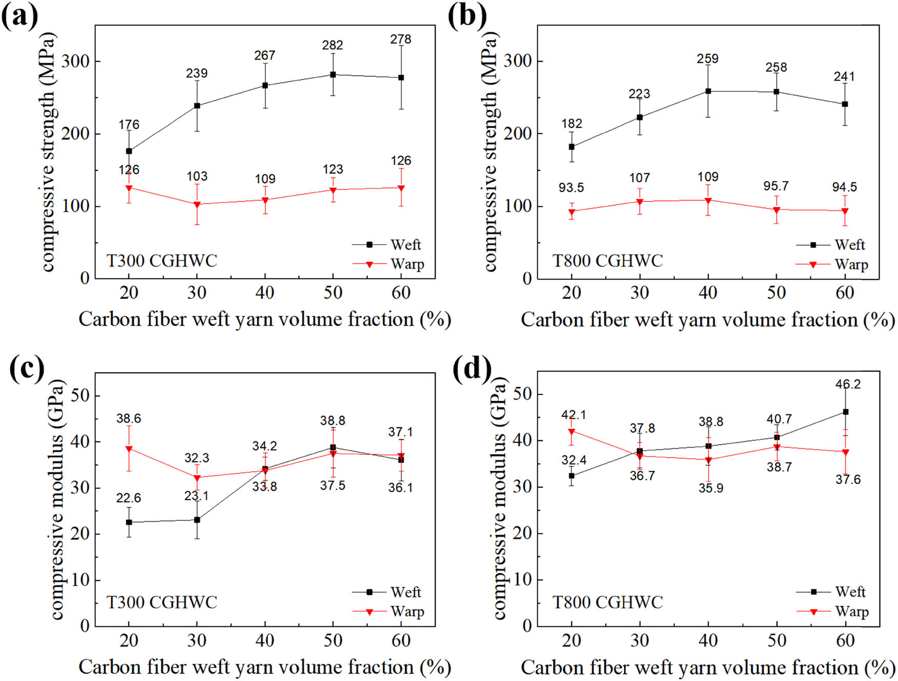
(a) Compressive strength and (c) modulus of 2.5D CGHWCs with T300 CGHWC, the (b) compressive strength and (d) modulus of 2.5D CGHWCs with T800 CGHWC.

Illustration of compressive process of 2.5D CGHWCs with different carbon fiber volume fractions.
The warp and weft compressive strength changes of T800 CGHWCs also exhibit a similar pattern, as depicted in Figure 9b. With the increase in carbon fiber volume fraction to 60%, the weft compressive strength of T800 CGHWC improves from 182 to 259 MPa, resulting in a 42% increase. Similar to T300 CGHWCs, the weft compressive strength of T800 CGHWCs enters a plateau region after the carbon fiber volume fraction surpasses 40%. However, the compressive strength within the plateau region of T800 CGHWCs is lower compared to that of T300 CGHWCs. This discrepancy arises from the thicker carbon fiber monofilament utilized in T300 carbon fibers, resulting in enhanced buckling resistance. Figure 9c and d demonstrates that the weft compressive modulus of both T300 CGHWC and T800 CGHWC gradually rises with an increase in carbon fiber volume fraction, while the warp compressive modulus exhibits negligible changes.
The pattern of compressive failure modes in T300 CGHWC and T800 CGHWC also shows similarities. The failure morphology after weft compressive testing of T300 CGHWC-20%, T300 CGHWC-30%, and T300 CGHWC-40% is displayed in Figure 11. T300 CGHWC-20% exhibits a typical compression failure mode with a 45° inclined fracture [21]. After undergoing compression testing, the carbon fiber and glass fiber weft yarns within the material become exposed on the surface of the sample due to compression-induced squeezing. The low modulus glass fibers are susceptible to fiber micro-buckling when subjected to axial compressive loads. Once the compressive load surpasses the critical point, the buckled fibers within the composite fracture lead to rapid expansion of cracks along the thickness direction of the composite. The fracture inclination angle of T300 CGHWC-30% increases to 55° (Figure 11b), with only resin fracture observed on the surface of the sample. Furthermore, near the fracture surface, glass fiber buckling was observed at the cross-section of the sample. With an increase in the proportion of high modulus carbon fibers, they play a crucial role in suppressing the micro-buckling of glass fibers under compressive loads. Additionally, when the critical load threshold is exceeded, carbon fibers also impede the extension of the fracture surface [22]. The aforementioned factors contribute to the enhancement of the compressive performance of the composites. The fracture inclination angle of T300 CGHWC-40% further increases to 80°, and the compression failure mode of T300 CGHWC-40% transitions from thickness-wise crushing to delamination failure along the axial direction (Figure 11c). When the proportion of high modulus carbon fibers is increased to 40%, the limiting effect of these fibers is further amplified. Beyond the critical load threshold, the buckling and fracture of glass fibers are confined to localized regions. The composite undergoes axial delamination when subjected to axial compression load, which is caused by the limitations in interfacial strength. This factor imposes limitations on the further enhancement of the compressive performance of the composites.

Failure morphology after weft compressive testing of T300 CGHWC with weft carbon fiber volume frictions of (a) 20%, (b) 30%, and (c) 40%.
The failure morphology after warp compressive testing of T300 CGHWC-20%, T300 CGHWC-30%, and T300 CGHWC-40% is depicted in Figure 12. It is observed that the compression failure modes of the three CGHWCs are consistent, with fiber buckling and compression collapse occurring in all cases. Similar to the warp tensile failure mode, the warp compressive failure mode of the CGHWCs demonstrates a weak correlation with the carbon fiber volume fraction.

Failure morphology after warp compressive testing of T300 CGHWC with weft carbon fiber volume frictions of (a) 20%, (b) 30%, and (c) 40%.
The mechanical performance characteristics of T300 CGHWC and T800 CGHWC resemble those of 2.5D pure carbon fiber composites. When comparing the two, T300 CGHWC exhibits approximately 8% higher compressive strength than T800 CGHWC, given the same carbon fiber volume fraction. On the other hand, T800 CGHWC demonstrates superior tensile performance, with a tensile strength approximately 15% higher than T300 CGHWC with the same carbon fiber volume fraction. Both CGHWC variations meet the mechanical requirements of the current external cable cover service environment for spacecraft. Moreover, T300 CGHWC offers a cost advantage, with a reduction of approximately 25% compared to T800 CGHWC. Due to this cost-effectiveness, T300 CGHWC is preferred as the external cable protection material for spacecraft.
3.4 Mechanical performance comparison of T300 2.5D CGHWC
T300 2.5D CGHWC exhibits outstanding mechanical properties while catering to the current requirements of low-cost production. Civilian grade T300 carbon fiber is more affordable, in comparison to military grade T300 carbon fiber, the cost of civilian grade carbon fiber can be reduced by up to 53%. To further decrease the production cost of 2.5D carbon glass composite materials, CGHWC-40% is the preferred choice. A comprehensive analysis of the mechanical properties of two grades of T300 CGHWC is conducted.
Figure 13a illustrates the weft and warp tensile and compressive strengths of military grade and civilian grade T300 CGHWC. The weft compressive strength of civilian grade T300 CGHWC can reach 96.2% of that of the military grade counterpart. The warp compressive strength of civilian grade and military grade T300 CGHWC is 109 and 116 MPa, respectively. Regarding tensile strength, the civilian grade T300 CGHWC achieves 98.6 and 91.7% of the military grade T300 CGHWC in the warp and weft directions, respectively. Figure 13b presents the weft and warp tensile and compressive moduli of military grade and civilian grade T300 CGHWC. The modulus of civilian grade T300 CGHWC can reach over 85% of the military grade counterpart.

(a) Mechanical strength and (b) modulus of 2.5D CGHWCs with military and civilian grade T300 carbon fiber.
The prices for civil T300, military T300, T800 carbon fiber, and SC240 glass fiber are 525, 1,100, 4,000, and 150 CNY/kg, respectively. Figure 14 displays the cost–performance relationship of T300 CGHWC-20%, military grade T300 CGHWC-40%, civilian grade T300 CGHWC-40%, T300 CGHWC-60%, and pure T300 CGHWC. The allowable values for the weft tensile and weft compressive design of external cable protection materials are 280 and 220 MPa, respectively, and military grade T300 CGHWC-40%, civilian grade T300 CGHWC-40%, T300 CGHWC-60%, and pure T300 CGHWC can meet the usage requirements. From the perspective of production economy, civil grade T300 CGHWC-40% (5,040 CNY/m2) emerges as the optimal choice for external cable protection materials in spacecraft applications. Ding et al. [23] and Song et al. [24] investigated that the tensile properties of 2.5D T300 carbon fiber woven composites were 463 and 432 MPa, respectively. The above results are similar to the 477 MPa tensile strength of 2.5D T300 carbon fiber woven composites in this article. Through the design of 2.5D carbon fiber/glass fiber hybrid braided structure, the tensile strength of the composite was successfully maintained above 300 MPa, and the cost of the composite was significantly reduced from 9,790 to 5,040 CNY/m2. The best balance between the mechanical properties and production cost of the 2.5D CGHWC was found.

Cost–performance relationship of T300 CGHWC-20%, military grade T300 CGHWC-40%, civilian grade T300 CGHWC-40%, T300 CGHWC-60%, and pure T300 CGHWC.
4 Conclusion
The weft performance of 2.5D carbon fiber woven composites surpasses that of the warp. This is attributed to the weaving structure of 2.5D straight shallow-crossing linking, which leads to multiple local bending of the warp yarn. Such bending can result in stress concentration and failure at the fiber bending point. On the other hand, the weft yarns can directly transmit stress, facilitating better synergistic interaction between the fibers and resins. T800 grade carbon fibers possess a regular carbon structure arrangement, which contributes to their outstanding tensile properties in 2.5D carbon fiber woven composites. Conversely, the T300 grade carbon fibers, with their large diameter monofilament, exhibit enhanced resistance to buckling. This makes their 2.5D carbon fiber woven composites particularly excellent in compression performance.
A similar trend can be observed in the mechanical properties of T300 and T800 grade 2.5D CGHWCs. As the carbon fiber volume fraction gradually increases, the weft mechanical properties of the composites improve. However, when the carbon fiber volume fraction reaches 40%, the rate of increase in weft mechanical strength begins to slow down and enters a plateau region. At this stage, the key factors influencing the mechanical properties of the composites are the limitations of interfacial strength, the ultimate tensile strength of glass fibers, and cumulative damage. With an increase in the proportion of carbon fibers, these limiting factors have a more significant impact, thereby weakening the enhancement of carbon fibers on the weft properties of the composite materials. Hence, the optimal carbon fiber volume fraction for 2.5D CGHWCs is determined to be 40%. Considering the cost aspect, T300 grade carbon fiber offers a 25% reduction in comparison to T800 grade carbon fiber. Consequently, T300 grade 2.5D CGHWCs are preferred as the external cable protection material for spacecraft applications.
The mechanical properties of civilian grade T300 2.5D CGHWCs can achieve over 85% of the performance of military-grade composites. Furthermore, these mechanical properties are still able to meet the design requirements for high-speed aircraft. In comparison to military-grade T300 carbon fiber, the cost of civilian grade T300 carbon fiber can be further reduced by 80%. Considering the balance between material mechanical properties and production costs, civilian grade T300 2.5D CGHWCs emerge as the most suitable choice for external cable protection materials in spacecraft applications.
-
Funding information: Authors state no funding involved.
-
Author contributions: All authors have accepted the responsibility for the entire content of this manuscript and consented to its submission to the journal, reviewed all the results and approved the final version of the manuscript. LZ, ZC, and YZ: manuscript preparation and revision; PH and ZL: data collection and analysis; YW and JW: conceptualization; TZ and ZC: experiment execution; YH: methodology; YZ and ZH: results interpretation.
-
Conflict of interest: Authors state no conflict of interest.
-
Data availability statement: All data generated or analyzed during this study are included in this published article.
References
[1] Mulligan JC, Colvin DP, Bryant YG. Microencapsulated phase-change material suspensions for heat transfer in spacecraft thermal systems. J Spacecr Rocket. 2012;33(2):278–84. 10.2514/3.26753.Search in Google Scholar
[2] Fabignon Y, Dupays J, Avalon G, Vuillot F, Lupoglazoff N, Casalis G, et al. Instabilities and pressure oscillations in solid rocket motors. Aerosp Sci Technol. 2003;7(3):191–200. 10.1016/S1270-9638(02)01194-X.Search in Google Scholar
[3] Katzman HA, Mallon JJ, Barry WT. Polyarylacetylene–matrix composites for solid rocket motor components. J Adv Mater. 1995;26(3):21–7. 10.1016/0142-1123(95)98943-W.Search in Google Scholar
[4] Li KZ, Shen XT, Li HJ, Zhang SY, Feng T, Zhang LL. Ablation of the carbon/carbon composite nozzle-throats in a small solid rocket motor. Carbon. 2011;49(4):1208–15. 10.1016/j.carbon.2010.11.037.Search in Google Scholar
[5] Ferraiuolo M, Manca O. Heat transfer in a multi-layered thermal protection system under aerodynamic heating. Int J Therm Sci. 2012;53:56–70. 10.1016/j.ijthermalsci.2011.10.019.Search in Google Scholar
[6] Gongnan X, Wang Q, Sunden B. Thermomechanical optimization of lightweight thermal protection system under aerodynamic heating. Appl Therm Eng. 2013;2:1–10. 10.1016/j. applthermaleng. 2013.06.002.Search in Google Scholar
[7] Navazi HM, Haddadpour H. Nonlinear aero-thermoelastic analysis of homogeneous and functionally graded plates in supersonic airflow using coupled models. Compos Struct. 2011;93(10):2554–65. 10.1016/j.compstruct.2011.04.018.Search in Google Scholar
[8] Wu DF, Wu S, Wang YW, Gao ZT, Yang JL. Fast and high precision thermoelectric potential – temperature conversion method for aerodynamic heating control systems. Adv Mater Res. 2013;694–697:955–60. 10.4028/www.scientific.net/AMR.694-697.955.Search in Google Scholar
[9] Yu HN, Longana ML, Jalalvand M. Pseudo-ductility in intermingled carbon/glass hybrid composites with highly aligned discontinuous fibres. Compos Part A Appl Sci Manuf. 2015;73A:35–44.10.1016/j.compositesa.2015.02.014Search in Google Scholar
[10] Mohamed MH, Wetzel KK. 3D woven carbon/glass hybrid spar cap for wind turbine rotor blade. J Sol Energy Eng. 2006;128(4):562–73. 10.1115/1.2349543.Search in Google Scholar
[11] Zhao Y, Song J, Wen W, Cui H, Li C, Liu S. Thermo-mechanical behaviors of 2.5D shallow straight-link-shaped woven composites under the warp direction fatigue loading at room and elevated temperatures. Compos Struct. 2022;289:115489.10.1016/j.compstruct.2022.115489Search in Google Scholar
[12] Song J, Wen W, Cui H. Experimental and numerical investigation of mechanical behaviors of 2.5D woven composites at ambient and un-ambient temperatures. Compos Struct. 2018;201:699–720.10.1016/j.compstruct.2018.06.054Search in Google Scholar
[13] Dang MG, Li DS, Jiang L. Temperature effects on mechanical response and failure mechanism of 3D angle-interlock woven carbon/epoxy composites. Compos Commun. 2020;18:37–42.10.1016/j.coco.2020.01.001Search in Google Scholar
[14] Hengsadeekul T, Nimityongskul P. Appropriate technology for low-cost housing by using precast vetiver grass-clay composite. J Ferrocem. 2005;35(3):628–40. 0125-1759(2005)35:3.Search in Google Scholar
[15] Hallal A, Younes R, Fardoun F. Improved analytical model to predict the effective elastic properties of a 2.5D interlock woven fabric composite. Compos Struct. 2012;94(10):3009–28. 10.1016/j.compstruct.2012.03.019.Search in Google Scholar
[16] Chen W, Yu Y, Li P. Effect of new epoxy matrix for T800 carbon fiber/epoxy filament wound composites. Compos Sci Technol. 2007;67(11–12):2261–70. 10.1016/j.compscitech. 2007.01.026.Search in Google Scholar
[17] Sheng Y, Zhang C, Xu Y, Lu C, Wu G, Wu Z, et al. Investigation of PAN-based carbon fiber microstructure by 2D-SAXS. Carbon. 2010;48(1):316. 10.1016/j.carbon.2009.09.025.Search in Google Scholar
[18] Opelt CV, Souza CSR, Marlet JMF, Cândido GM, Rezende MC. Compression failure modes of carbon fiber fabric scraps/epoxy laminates. Adv Mater Res. 2016;1135:52–61. 10.4028/www.scientific.net/AMR.1135.52.Search in Google Scholar
[19] Willows ML. An energy based damage mechanics approach to modelling impact onto woven composite materials: Part II. Experimental and numerical results. Compos Part A Appl Sci Manuf. 2007;38a(1):540–54.10.1016/j.compositesa.2006.02.023Search in Google Scholar
[20] Radulovi J. Hybrid filament-wound materials: tensile characteristics of (aramide fiber/glass fiber)-epoxy resins composite and (carbon fibers/glass fiber)-epoxy resins composites. Sci Tech Rev. 2020;70(1):36–46. 10.5937/STR2001036R.Search in Google Scholar
[21] Xu L, Fei BQ, Ma SH, Hui L, Huang GD. Tensile and compress property of composite laminate in hygrothermal environment. Cailiao Gongcheng/J Mater Eng. 2018;46(3):124–30. 10.11868/j.issn.1001-4381.2016.000632.Search in Google Scholar
[22] Harper JF, Michiels SJ. The behaviour of polyphenylene sulphide carbon/glass hybrid composites under compressive loading. Key Eng Mater. 1998;144:17–26. 10.4028/www.scientific.net/KEM.144.17.Search in Google Scholar
[23] Ding YQ, Yan Y, Mcilhagger R, Brown D. Comparison of the fatigue behaviour of 2-D and 3-D woven fabric reinforced composites – ScienceDirect. J Mater Process Technol. 1995;55(3–4):171–7. 10.1016/0924-0136(95)01950-2.Search in Google Scholar
[24] Song J, Cui H. Elevated temperature fatigue and failure mechanism of 2.5D T300/QY8911-IV woven composites[C]. The 7th International Conference (ICCM 2016) on Computational Methods. Berkeley, CA, USA; 2016.Search in Google Scholar
© 2024 the author(s), published by De Gruyter
This work is licensed under the Creative Commons Attribution 4.0 International License.
Articles in the same Issue
- Regular Articles
- Research on damage evolution mechanisms under compressive and tensile tests of plain weave SiCf/SiC composites using in situ X-ray CT
- Structural optimization of trays in bolt support systems
- Continuum percolation of the realistic nonuniform ITZs in 3D polyphase concrete systems involving the aggregate shape and size differentiation
- Multiscale water diffusivity prediction of plain woven composites considering void defects
- The application of epoxy resin polymers by laser induction technologies
- Analysis of water absorption on the efficiency of bonded composite repair of aluminum alloy panels
- Experimental research on bonding mechanical performance of the interface between cementitious layers
- A study on the effect of microspheres on the freeze–thaw resistance of EPS concrete
- Influence of Ti2SnC content on arc erosion resistance in Ag–Ti2SnC composites
- Cement-based composites with ZIF-8@TiO2-coated activated carbon fiber for efficient removal of formaldehyde
- Microstructure and chloride transport of aeolian sand concrete under long-term natural immersion
- Simulation study on basic road performance and modification mechanism of red mud modified asphalt mixture
- Extraction and characterization of nano-silica particles to enhance mechanical properties of general-purpose unsaturated polyester resin
- Roles of corn starch and gellan gum in changing of unconfined compressive strength of Shanghai alluvial clay
- A review on innovative approaches to expansive soil stabilization: Focussing on EPS beads, sand, and jute
- Experimental investigation of the performances of thick CFRP, GFRP, and KFRP composite plates under ballistic impact
- Preparation and characterization of titanium gypsum artificial aggregate
- Characteristics of bulletproof plate made from silkworm cocoon waste: Hybrid silkworm cocoon waste-reinforced epoxy/UHMWPE composite
- Experimental research on influence of curing environment on mechanical properties of coal gangue cementation
- Multi-objective optimization of machining variables for wire-EDM of LM6/fly ash composite materials using grey relational analysis
- Synthesis and characterization of Ag@Ni co-axial nanocables and their fluorescent and catalytic properties
- Beneficial effect of 4% Ta addition on the corrosion mitigation of Ti–12% Zr alloy after different immersion times in 3.5% NaCl solutions
- Study on electrical conductive mechanism of mayenite derivative C12A7:C
- Fast prediction of concrete equivalent modulus based on the random aggregate model and image quadtree SBFEM
- Research on uniaxial compression performance and constitutive relationship of RBP-UHPC after high temperature
- Experimental analysis of frost resistance and failure models in engineered cementitious composites with the integration of Yellow River sand
- Influence of tin additions on the corrosion passivation of TiZrTa alloy in sodium chloride solutions
- Microstructure and finite element analysis of Mo2C-diamond/Cu composites by spark plasma sintering
- Low-velocity impact response optimization of the foam-cored sandwich panels with CFRP skins for electric aircraft fuselage skin application
- Research on the carbonation resistance and improvement technology of fully recycled aggregate concrete
- Study on the basic properties of iron tailings powder-desulfurization ash mine filling cementitious material
- Preparation and mechanical properties of the 2.5D carbon glass hybrid woven composite materials
- Improvement on interfacial properties of CuW and CuCr bimetallic materials with high-entropy alloy interlayers via infiltration method
- Investigation properties of ultra-high performance concrete incorporating pond ash
- Effects of binder paste-to-aggregate ratio and polypropylene fiber content on the performance of high-flowability steel fiber-reinforced concrete for slab/deck overlays
- Interfacial bonding characteristics of multi-walled carbon nanotube/ultralight foamed concrete
- Classification of damping properties of fabric-reinforced flat beam-like specimens by a degree of ondulation implying a mesomechanic kinematic
- Influence of mica paper surface modification on the water resistance of mica paper/organic silicone resin composites
- Impact of cooling methods on the corrosion behavior of AA6063 aluminum alloy in a chloride solution
- Wear mechanism analysis of internal chip removal drill for CFRP drilling
- Investigation on acoustic properties of metal hollow sphere A356 aluminum matrix composites
- Uniaxial compression stress–strain relationship of fully aeolian sand concrete at low temperatures
- Experimental study on the influence of aggregate morphology on concrete interfacial properties
- Intelligent sportswear design: Innovative applications based on conjugated nanomaterials
- Research on the equivalent stretching mechanical properties of Nomex honeycomb core considering the effect of resin coating
- Numerical analysis and experimental research on the vibration performance of concrete vibration table in PC components
- Assessment of mechanical and biological properties of Ti–31Nb–7.7Zr alloy for spinal surgery implant
- Theoretical research on load distribution of composite pre-tightened teeth connections embedded with soft layers
- Coupling design features of material surface treatment for ceramic products based on ResNet
- Optimizing superelastic shape-memory alloy fibers for enhancing the pullout performance in engineered cementitious composites
- Multi-scale finite element simulation of needle-punched quartz fiber reinforced composites
- Thermo-mechanical coupling behavior of needle-punched carbon/carbon composites
- Influence of composite material laying parameters on the load-carrying capacity of type IV hydrogen storage vessel
- Review Articles
- Effect of carbon nanotubes on mechanical properties of aluminum matrix composites: A review
- On in-house developed feedstock filament of polymer and polymeric composites and their recycling process – A comprehensive review
- Research progress on freeze–thaw constitutive model of concrete based on damage mechanics
- A bibliometric and content analysis of research trends in paver blocks: Mapping the scientific landscape
- Bibliometric analysis of stone column research trends: A Web of Science perspective