Experimental investigation of the performances of thick CFRP, GFRP, and KFRP composite plates under ballistic impact
-
Heriana

 ,
Leonardo Gunawan
,
Leonardo Gunawan

Abstract
This study discusses the experimental results of the ballistic impact on thick-layered carbon fibre-reinforced polymer (CFRP), glass-based FRP (GFRP), and Kevlar-based FRP (KFRP) composite plates. Ten 10 mm plates of each type were manufactured via the hand lay-up and vacuum bagging techniques to produce plates with a thickness of 2 mm each, which were bonded together using epoxy adhesive and hot pressed at 75°C to obtain thick layered plates with a total thickness of 20 mm each. The specimen plates were tested according to the NIJ 0108.01 standard in a special firing room using a 9 mm G2 Elite handgun with a full metal jacketed round nose 9 mm × 19 mm Mu1-TJ bullets moving at a velocity of approximately 358 m/s. The results indicated that no total penetration occurred on any of the plates. The bullets were destroyed by impact, and the penetration depths of the CFRP, GFRP, and KFRP plates were 11.10, 9.95, and 22.22%, respectively. The layered structures in these plates appear to have changed the penetration behaviour compared with previous studies. In this study, delamination was the primary failure mode.
1 Introduction
Owing to the risks of high-velocity ballistic impact damage in various fields, such as military and aerospace industries, an adequate ballistic protection system is required. These concerns are vital because high-velocity impacts from different projectiles can endanger the prolonged functionality of impacted components, resulting in substantial damage and even cause fatalities in extreme cases.
With the advancement in military operations and weapons, the demand for ballistic body armour that can resist damage from ballistic threats while maintaining comfort, flexibility, and high mobility for the wearer has also increased. Furthermore, similar impact risks exist in other applications, such as interiors of turbines and aircrafts or spacecraft exteriors (e.g. runway debris or bird strikes). Consequently, ballistic-resistant structures are essential in these related fields [1].
Currently, fibre-reinforced polymer (FRP) composite laminates are commonly used in ballistic protection due to their high specific strength, weight-saving potential, and energy-absorbing characteristics. However, FRP plates are structurally more complicated than isotropic materials due to the macroscopic combination of fibres and matrices. During ballistic impact, they undergo a complex damage propagation process and failure mechanism. These damages include fibre breakage, matrix cracking, delamination, and interfacial debonding, which occur as the composite plates experience shear plugging, cone deformation, or perforation due to impact [2].
Understanding the response behaviour of these materials to relevant ballistic threats is indispensable for creating the most effective and optimized designs. The influence of changes in the impact parameters, targets, and projectiles on the ballistic performance of the FRPs has been previously analysed. Increasing the aspect ratio [3], thickness [4], bluntness of the projectile nose shape [5], and impact obliquity angles [6,7] was found to improve the ballistic performance significantly, as observed from the smaller residual velocity and greater energy absorption.
With respect to damage characterization analysis, studies on the damage characteristics of high-velocity impact damage in carbon-based FRP (CFRP) laminates and identification of crater formation, delamination, and f breakage have been conducted [8]. A numerical comparative study of glass-based FRP (GFRP) and CFRP composites with varying stacking sequences against a blunt-nose projectile revealed the superior ballistic performance of CFRPs owing to their higher strength and stiffness compared to GFRP [9], whereas an analysis of the ballistic resistance of polyurea-coated CFRP laminates under projectile impact loading revealed the improved performance of the coated plates [10]. Fibre breakage, matrix failure, debonding between the fibres and matrix, fibre pull-out, delamination, conically shaped deformations, and shear failure were identified.
Ballistic impact-response analysis or optimization is typically performed experimentally to ensure the reliability of the results. However, ballistic experimentation investigation of the ballistic performance of FRP laminates can be quite expensive, especially when CFRP and/or Kevlar®/aramid-based fibre FRP (KFRP/AFRP) materials are involved. This limitation can be overcome by using finite-element modelling. Most ballistic experimental studies are accompanied by a numerical model for comparison, which offers quicker analysis and optimization capabilities.
A comparison of two-scale numerical modelling, a microstructural model (MSM) and a continuum-based model, was conducted [11]. The MSM scale modelled the yarns, enabling the simulation of composite delamination and complex intralayer fractures. Good agreement between the ballistic curves of both models and the experimental results was observed. A mixed macro-homogeneous and meso-heterogeneous approach has also been used to model composite plates [12,13], which allows the observation of yarn and matrix interaction in the near-impact area, while saving computational costs using macro-homogeneous modelling in areas further from the impact point, where the yarn and matrix are considered a single homogeneous entity. A similar scale of modelling defines the individual plies in which full three-dimensional stress states are considered [14]. This model allows the analysis of the interactions between the intralayer and interlayer damage mechanisms. Another study compared this numerical model with a simpler model without interlaminar damage modelling, and a good agreement was observed between the numerical and experimental models [15].
Most of the aforementioned studies were based on thin plates, whereas this study concentrated on thick plates. Naik and Doshi [16] discussed the analytical and experimental studies on thick GFRP plates. They developed a wave propagation model to analyse ballistic impacts and found that shear plugging and friction absorbed most of the impact energy, whereas matrix cracking and delamination did not absorb significant impact energy. The experiment was performed using a 7 mm thick GFRP plate with a cylindrical projectile having a flat end diameter of 6.33 mm and a mass of 5.84 g with a ballistic velocity of 174.22 m/s. No penetration was observed.
In this study, the behaviour of CFRP, GFRP, and KFRP composite thick plates under ballistic impact was experimentally investigated. Layered plates of each type were produced using hand lay-up and vacuum bagging techniques. First, 10 mm plates were manufactured using these techniques, producing plates with a thickness of 2 mm. They were then bonded together using epoxy adhesive and hot pressed at 75°C to obtain thick layered plates with a total thickness of approximately 20 mm. The specimens were then fired using bullets in a special firing room according to the National Institute of Justice (NIJ 0108.01) ballistic standard. The resulting impacted plates were further investigated. Current manufacturing methods were intentionally maintained to obtain thick layered composite plates.
The difference between this research and other research is that this research concentrates on layered structures, compared to solid structures before. We could not find any literature based on layered structures. That will affect the failure modes. Naik and Doshi [16], in which shear plugging was the dominant failure modes, found out that it may be that in layered structures, delamination will be the dominant failure modes. The layered structures may change the behaviour of impact energy absorption from shear plugging to delamination. Also, we will use deformable bullets. Therefore, bullet deformation will also absorb impact energy.
The difference between this research and other studies is that this study concentrated on layered rather than solid structures. We could not find any studies based on layered structures that can affect the failure mode. A previous study [16] reported shear plugging to be the dominant failure mode; however, delamination may be the dominant failure mode in layered structures, that is, the layered structures may change the behaviour of impact energy absorption from shear plugging to delamination. In addition, a deformable bullet was used in this study. Therefore, bullet deformation may also result in impact energy absorption.
2 Specimen preparations
The materials used in this experimentation are given in Table 1. First, ten layers of fabric were stacked together, mixed with resin and hardener, vacuumed, and left in room temperature for 24 h until it was fully cured. We made ten plates using this technique. The thickness is around 2 mm per plate. After completion, we bonded the ten plates together using epoxy resin, put it in the hot press, and pressed it at 75°C for 2 h until it was totally bonded and was completed. Therefore, the plates were in the form of layered structures, as seen in Figure 1. The total thickness is around 20 mm.
Materials used during the experiments
| Materials | Types |
|---|---|
| Carbon fibre | Twill weave 2 × 2 HDC 524-3K fibres with a single sheet thickness of 0.22 mm |
| Glass fibre | Plain weave E-Glass WR 200 fibres with a single sheet thickness of 0.22 mm |
| Kevlar fibre | Plain weave para-aramid fibres with a single sheet thickness of 0.28 mm |
| Epoxy | Unmodified, liquid standard epoxy resin based on Bisphenol-A, with a density (25°C) of 1.17 g/cm3 |
| Hardener | A very low-viscosity cycloaliphatic amine curing agent for liquid and solid epoxy resins, used with a resin-to-hardener ratio of 2:1 |

Side view of the composite plate specimens: (a) 27.1 mm CFRP, (b) 20.6 mm GFRP, and (c) 30.2 mm KFRP.
3 Test standard, set-up, and procedure
3.1 Mechanical properties
Tensile and compression tests were carried out to obtain the mechanical characteristics of the materials used during ballistic tests, which are GFRP, KFRP, and CFRP. The tensile tests were done according to ASTM D3039 [17], while the compression tests were carried out using ASTM D3410 [18]. The stress–strain curves are given in Figure 2. The resulting tensile and compression strengths and modulus of elasticity are given in Table 2.

Tensile and compressive stress–strain of (a) GFRP, (b) CFRP, and (c) KFRP coupon tests.
Mechanical characteristics of GFRP, CFRP, and KFRP specimens
| GFRP | CFRP | KFRP | |
|---|---|---|---|
| Tensile modulus (GPa) | 20.22 | 55.51 | 16.50 |
| Tensile strength (MPa) | 547.87 | 714.42 | 544.89 |
| Maximum tensile strain (%) | 2.87 | 1.29 | 3.44 |
| Compressive modulus (GPa) | 20.1 | 52.50 | 21.39 |
| Compressive strength (MPa) | 309.6 | 261.6 | 57.6 |
| Maximum compressive strain (%) | 1.6 | 0.5 | 0.34 |
3.2 Ballistic tests
The ballistic impact experiment was designed to follow the NIJ 0108.01 standard [19] as it sets the minimum performance requirements and methods of testing for ballistic resistance protective material. Although this ballistic resistance test is not aimed at creating an actual standardized ballistic resistance protective material, NIJ 0108.01 is still used so that the quality of the ballistic performance of each specimen can be compared with a recognizable standard. Table 3 shows the standard, while Figure 3 shows the test set-up according to the NIJ 0108.01 standard.
Ballistic performance requirements based on NIJ 0108.01 [16]
| Armor type | Test ammunition | Nominal bullet mass | Suggested barrel length | Required bullet velocity | Required hits per armour specimen | Number of allowed failure |
|---|---|---|---|---|---|---|
| I | 22 LRHV | 2.6 g | 15–16.5 cm | 320 ± 12 m/s | 5 | 0 |
| Lead | 40 g | 6–6.5 in | 1,050 ± 40 ft/s | |||
| 38 Special RN | 10.2 g | 15–16.5 cm | 259 ± 15 m/s | 5 | 0 | |
| Lead | 158 g | 6–6.5 in | 850 ± 50 ft/s | |||
| II-A | 357 Magnum | 10.2 g | 10–12 cm | 381 ± 15 m/s | 5 | 0 |
| JSP | 158 g | 4–4.75 in | 1,250 ± 50 ft/s | |||
| 9 mm FMJ | 8.0 g | 10–12 cm | 332 ± 12 m/s | 5 | 0 | |
| 124 g | 4–4.75 in | 1,090 ± 40 ft/s | ||||
| II | 357 Magnum | 10.2 g | 15–16.5 cm | 425 ± 15 m/s | 5 | 0 |
| JSP | 158 g | 6–6.5 in | 1,395 ± 50 ft/s | |||
| 9 mm FMJ | 8.0 g | 10–12 cm | 358 ± 12 m/s | 5 | 0 | |
| 124 g | 4–4.75 in | 1,175 ± 40 ft/s | ||||
| III-A | 44 Magnum | 15.55 g | 14–16 cm | 426 ± 15 m/s | 5 | 0 |
| Lead SWC Gas | 240 g | 5.5–6.25 in | 1,400 ± 50 ft/s | |||
| Checked | ||||||
| 9 mm FMJ | 8.0 g | 24–26 cm | 426 ± 15 m/s | 5 | 0 | |
| 124 g | 9.5–10.25 in | 1,400 ± 50 ft/s | ||||
| III | 7.62 mm | 9.7 g | 56 cm | 838 ± 15 m/s | 5 | 0 |
| 308 Winchester | 150 g | 22 in | 2,850 ± 50 ft/s | |||
| FMJ | ||||||
| IV | 30-06 AP | 10.8 g | 56 cm | 868 ± 15 m/s | 1 | 0 |
| 166 g | 22 in | 2,850 ± 50 ft/s |
AP – armor piercing; FMJ – full metal jacket; JSP – jacketed soft point; LRHV – long rifle high velocity; RN – round nose; SWC – semi-wadcutter.
![Figure 3
Ballistic test set-up (a) and real experimental set-up (b) according to NIJ 0108.01 [19].](/document/doi/10.1515/secm-2022-0240/asset/graphic/j_secm-2022-0240_fig_003.jpg)
Ballistic test set-up (a) and real experimental set-up (b) according to NIJ 0108.01 [19].
The specimens will be shot five times with a “fair shot” with a 9 mm FMJ RN moving at the velocity of around 358 m/s. For this research, the 9 mm FMJ used will be a 9 mm × 19 mm MU1-TJ bullet that will be shot with a G2 Elite handgun. The basic specifications of the gun and bullet are shown in Tables 4 and 5, as well as in Figures 4 and 5.
G2 elite specifications
| Parameter | Value | Unit | Source |
|---|---|---|---|
| Capacity | 15 | rounds | Manufacturer |
| Barrel length | 127 | mm | Manufacturer |
| Barrel rifling | 6 | grooves | Manufacturer |
| Grooves | 1:10 right hand twist | — | Manufacturer |
| Weight | 1 ± 0.05 | kg | Manufacturer |
| Overall length | 221 | mm | Manufacturer |
| Height | 139 | mm | Manufacturer |
| Front sight | Fixed | — | Manufacturer |
| Rear sight | Adjustable/fixed | — | Manufacturer |
| Effective range | 25 | mm | Manufacturer |
| Caliber | 9 × 19 | mm | Manufacturer |
| Operation/action | Single action, semi auto | — | Manufacturer |
MU1-TJ bullet specification
| Parameter | Value | Unit | Source |
|---|---|---|---|
| Cartridge | |||
| Weight | 12.26 | g | Manufacturer |
| Rim thickness | 1.25 | mm | Manufacturer |
| Extractor length | 8.8 | mm | Manufacturer |
| Bullet | |||
| Length | 15.7 | mm | Manufacturer |
| Weight | 8 | g | Manufacturer |
| Core material | Lead antimony | — | Manufacturer |
| Jacket material | Brass 72 (CuZn 28) | — | Manufacturer |
| Type | Full Metal Jacket Round Nose (FMJ RN) | — | Manufacturer |
| Case | |||
| Material | Brass 72 (CuZn 28) | — | Manufacturer |
| Type | Rimless, conical, and centrefire | — | Manufacturer |
| Primer | |||
| Type | Non-corrosive, non-mercuric | — | Manufacturer |
| Propellant | |||
| Type | Smokeless powder | — | Manufacturer |
| Characteristics | |||
| Average velocity | 380 | m/s | Manufacturer |

G2 Elite PINDAD.
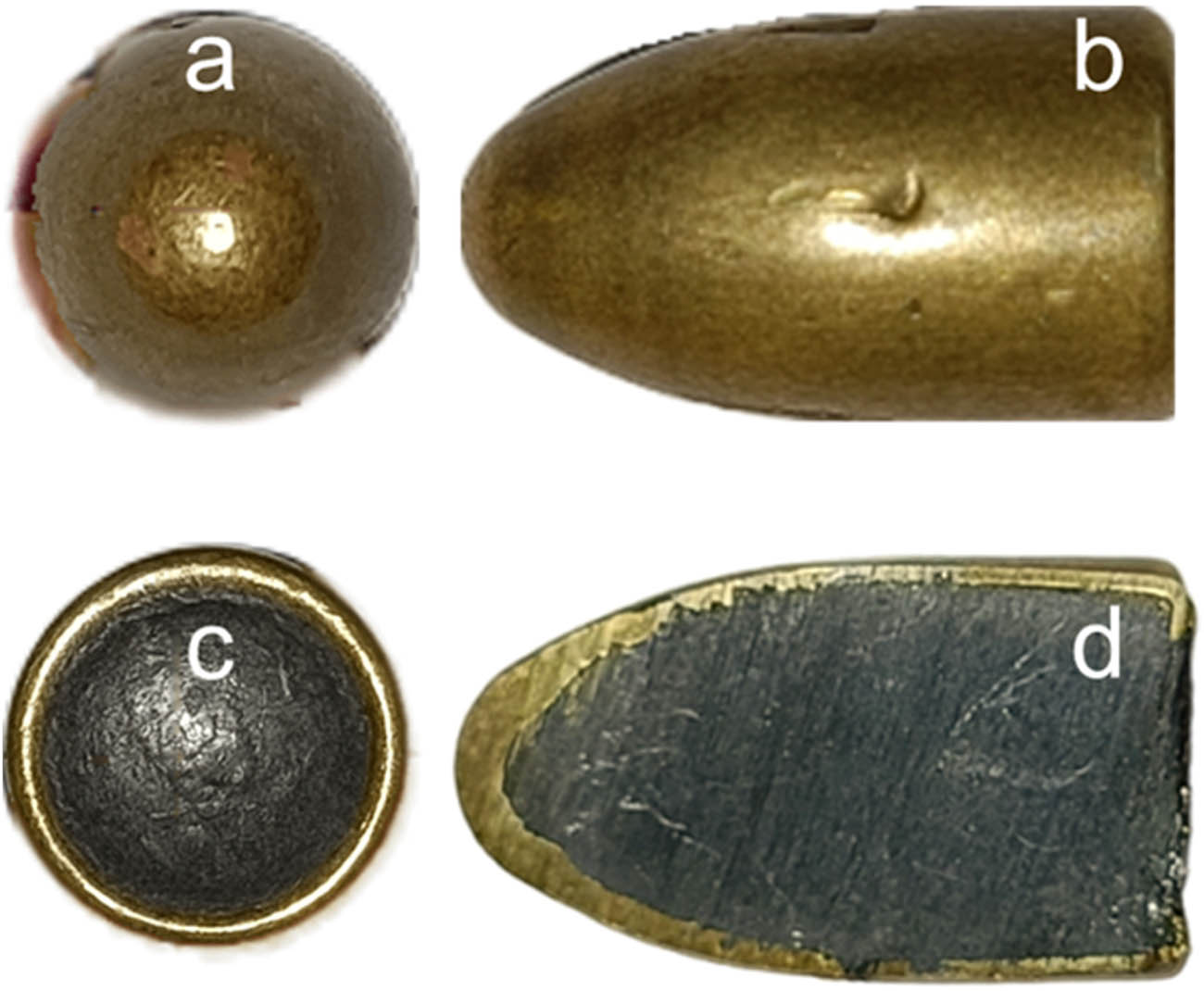
MU1-TJ bullet: (a) front view, (b) side view, (c) back view, and (d) cross-sectional view.
4 Experimental results and analysis
A ballistic impact experiment based on the NIJ 0108.01 standard conducted on three composite plate specimens (CFRP, GFRP, and KFRP) has been successfully done. The CFRP, GFRP, and KFRP specimens were impacted, respectively, by six bullets, five bullets, and seven bullets. Each specimen was impacted by at least five fair hits. The results show that none of the fair hits fully penetrated any of the specimens, only resulting in partial penetrations. In other words, all specimens have successfully stopped ballistic impact from five Type II NIJ 0108.01 standardized fair hits.
Every impact velocity of the bullet has been recorded successfully by the light gates and chronograph. The averaged velocity for each fair hit for the CFRP, GFRP, and KFRP specimens, respectively, are 357.42, 357.80, and 355.72 m/s. All the recorded fair hit velocities conform to the Type II armour specifications for a 9 mm FMJ bullet, which is 358 ± 12 m/s.
The final experiment data sheet is presented in Table 6. The hit coordinate is written in mm, where the most bottom left point of the specimen shall be considered the origin point (0, 0) while the most top right point of the specimen is considered the point (200, 200). Penetration depth is only measured for one impact since each specimen is only cut once. The purpose of this cross-sectional cut is so that the through thickness damage can be observed. For CFRP, GFRP, and KFRP specimens, the line of the cut is aligned to impact hole numbers 3, 1, and 2, respectively (refer to the dotted lines in Figures 6, 8 and 10). Those impact holes are chosen because, in their respective specimen, they are the most isolated penetration holes compared to the other ones. This consideration is taken so that the observed through-thickness damage is mostly caused by the corresponding bullet only and not caused by cumulative damage of several impacts.
Ballistic impact experiment results
| Specimen | Impact number | Bullet velocity (m/s) | Description | Hit coordinate (x, y in mm) | Penetration | Penetration depth (mm) | SEA (J/kg) |
|---|---|---|---|---|---|---|---|
| CFRP | 1 | 355.3 | Fair hit | 102.3, 53 | Partial | — | 345.86 |
| 2 | 362.1 | Fair hit | 112.6, 135.7 | Partial | — | 359.22 | |
| 3 | 360.7 | Fair hit | 62.2, 135.7 | Partial | 3.01 (11.10%) | 356.45 | |
| 4 | 348.4 | Fair hit | 57.1, 93.6 | Partial | — | 332.55 | |
| 5 | 368.1 | Invalid | N/A | — | — | — | |
| 6 | 362.5 | Fair hit | 108, 186.1 | Partial | — | 360.02 | |
| GFRP | 1 | 352.8 | Fair hit | 125, 126.5 | Partial | 2.05 (9.95%) | 358.18 |
| 2 | 357.0 | Fair hit | 57.4, 116.2 | Partial | — | 366.76 | |
| 3 | 359.6 | Fair hit | 69.1, 44.1 | Partial | — | 372.12 | |
| 4 | 351.6 | Fair hit | 113.2, 31.4 | Partial | — | 355.75 | |
| 5 | 366.1 | Fair hit | 94.1, 69.6 | Partial | — | 385.69 | |
| KFRP | 1 | 352.3 | Fair hit | 89.6, 82.1 | Partial | — | 233.31 |
| 2 | 357.6 | Fair hit | 107, 144.3 | Partial | 6.71 (22.22%) | 236.82 | |
| 3 | 355.8 | Invalid angle | N/A | — | — | — | |
| 4 | 355.8 | Fair hit | 49.8, 138.8 | Partial | — | 235.62 | |
| 5 | 354.4 | Fair hit | 65.2, 140.2 | Partial | — | 234.70 | |
| 6 | 359.3 | Missed hit | N/A | — | — | — | |
| 7 | 358.5 | Fair hit | 76.1, 80.1 | Partial | — | 237.41 |

CFRP specimen impacted front (the dotted line shows the cutting location).
Another important criterion for the impact problem is specific energy absorption (SEA). SEA is defined as the energy absorbed per unit weight, given in J/kg. Table 6 shows the SEA for different plates, GFRP, CFRP, and KFRP. Table 6 shows that the SEA of GFRP is the highest, with the SEA of 367 J/kg and KFRP is the lowest at 235 J/kg. CFRP is at 350 J/kg. It shows that GFRP is the most efficient in absorbing the ballistic impact for layered thick composite plates.
4.1 Carbon fibre epoxy
The impacted carbon epoxy plate can be seen in Figure 6.
As seen in Figure 6, each impacted hole of the fair hit on the CFRP specimen is very localized, showing a small, damaged area for each hit compared to the bullet impact size itself. No total penetration occurred. From this point of view, each fair hit shows damaged and pulled-out fibre but no apparent delamination. The specimen was then cut by a water jet to show the damaged area through the thickness. The damaged cut is shown in Figure 7.

CFRP specimen sectioned view: (a) left side of the cut, and (b) right side of the cut, mirrored.
Through thickness, damages are more identifiable, as seen in Figure 7. Identifiable damage details have been marked with numbers (correspond the numbers below with the number marks in Figure 7):
Delamination of the first two topmost ply groups from impact number 4,
Entrance damage of impact number 4,
Entrance damage of impact number 3,
Delamination of the topmost ply group from impact number 3,
Bullet fragments from impact number 3,
Ply group delamination from impact number 6,
Ply group delamination from poor bonding,
Bullet fragments from impact number 4,
Delamination of the topmost ply group from impact numbers 3 and 4,
Entrance damage of impact number 3,
Delamination of a single ply from impact number 3, and
Ply group delamination from impact number 6.
From Figure 7, some noticeable remarks about the damages are as follows:
Bullet entrance damage (marked 2 and 3) shows clean, brittle, and localized damage. It is also noticeable that there is a slight conical deformation protruding towards the opposite of the bullet’s travel direction.
Bullets are extremely deformed and fragmented. They are clearly stuck between delaminated ply groups (marked 5 and 8). Delamination of ply groups creates ample space for bullet fragments to spread and get stuck under.
There is delamination of ply groups closer to the back surface of the specimen (marked 6, 7, and 12). It must be noted that they are not directly impacted by the bullets, yet the delamination is still present. It is probable that the reason for this phenomenon is poor bonding between ply groups which then is triggered by the wave propagation and vibrations from several impacts.
There is one apparent single-ply delamination (marked 11). However, observing the rest of the specimen, ply group delamination is more prominent. The lack of single-ply delamination in contrast to ply group delamination must be caused by the fact that the bonding and curing process of each ply group is more thorough since it uses the vacuum bagging process while bonding between ply groups is only done with a hot press machine and resin impregnation within fibres are not possible.
4.2 Glass fibre composites
The resulting impacted glass fibre composites are given in Figure 8.

GFRP specimen impacted front (the dotted line shows the cutting location).
Figure 8 shows the impacted front of the GFRP specimen, which was impacted by five fair hits. Consistent with the CFRP specimen, each penetration hole is localized. However, what is prominent with the GFRP specimen is that the damaged area can be seen more clearly around the penetration hole. This is shown by the lighter-coloured circles surrounding each impacted hole, signifying a delamination area on the topmost layers nearest the impacted front. However, this observable delamination damage is more pronounced since glass fibres are generally quite transparent in the first place. Again, no total penetration happened. Figure 9 shows the thickness damage area of the specimens.

GFRP specimen sectioned view: (a) left side of the cut, and (b) right side of the cut, mirrored.
Through thickness, damages of the GFRP specimen are shown in Figure 9. Identifiable damage details have been marked with numbers (correspond the numbers below with the number marks in Figure 9):
Damage and delamination from impact number 4,
Ply group delamination and bullet fragments from impact number 5,
Bullet fragments from impact number 1,
Entrance damage of impact number 1,
Bullet fragments from impact number 3,
Ply group delamination from poor bonding,
Damage and delamination from impact number 4,
Ply group delamination from impact number 5,
Delamination of a single ply from impact number 1,
Entrance damage of impact number 1, and
Ply group delamination from impact number 1.
Figure 9 shows damages that are consistent with the remarks of Figure 8. Bullet entrance damage shows localized damage and there was an apparent conical deformation towards the opposite of the bullet’s travel direction. Bullets are also extremely deformed and stuck in the delamination space between ply groups. There are ply groups delamination which are not directly connected to the bullet’s path, and single-ply delamination is also present. It is consistent how most of the damages are dominated by ply group delamination.
4.3 Kevlar fibre composites
Figure 10 shows the impacted Kevlar fibre composites.

KFRP specimen impacted front (the dotted line shows the cutting location).
Figure 10 shows the impacted front of the KFRP specimen, which was impacted by five fair hits and two invalid hits. All impacted holes are localized, and damaged fibres are only present very tightly near the bullet entrances. There are several closely placed impacts, which would not count as a fair hit if full penetration occurred. However, even when there were several closely packed impacts, there were still no full penetrations. This shows the ability of KFRP to adequately absorb the ballistic impacts. Figure 11 shows the thickness damaged area of the Kevlar composites.

KFRP specimen sectioned view: (a) left side of the cut, and (b) right side of the cut, mirrored.
Through thickness, damages of the KFRP specimen are shown in Figure 11. Identifiable damage details have been marked with numbers (correspond the numbers below with the number marks in Figure 11):
Bullet fragments from impact number 1,
Ply group delamination from poor bonding,
Ply group delamination from impact number 1,
Entrance damage of impact number 2,
Bullet fragments and delamination of ply group from impact number 2,
Delamination of a single ply from impact number 1 and 7,
Bullet fragments from impact number 1 and 7 stuck between ply groups,
Delamination of ply groups from impact number 1 and 7,
Delamination of ply groups from impact number 2,
Delamination of a single ply from impact number 2,
Entrance damage of impact number 2,
Delamination of a single ply from poor bonding, and
Delamination of a single ply from impact number 2.
Figure 11 shows similar damage results compared to Figures 7 and 9. What is most noticeably different for the KFRP specimen is that single-ply delamination is more prominent. Considering that seams between ply groups for KFRP are also the most noticeable, it can be safely stated that KFRP has the least thorough resin impregnation for inner ply bonding and bonding between ply groups. However, even when this is the case, it cannot be directly stated that this phenomenon causes a lack of ballistic performance since the KFRP plate still absorbed every bullet’s kinetic energy.
Ultimately, all the manufactured impact targets were adequately performed when impacted with a Type II NIJ 0108.01 ballistic threat, which is the most common in the context of firearm threats. Furthermore, the penetration depth for observed impact is only 11.10% (CFRP), 9.95% (GFRP), and 22.22% (KFRP). This shows that these targets could still absorb more kinetic energy from a ballistic impact, considering that there is no noticeable back-face deformation for all of them.
The resulting comparisons between the specimens are shown in Table 7, which shows conclusively a comprehensive visual observation comparison between all specimens before and after the experiment. It should be noted that while the GFRP plate resulted in the best relative ballistic performance in terms of bullet penetration percentage, it is also the heaviest. While KFRP is the lightest of them all, it is the most expensive, and the relative penetration is the largest. On the other end, CFRP has the middle of the pack density, with only 11% bullet penetration.
Ballistic impact specimen and experiment results comparison
| Parameter | Specimen | ||
|---|---|---|---|
| CFRP | GFRP | KFRP | |
| Specimen similarities | |||
| Impact area dimensions | 200 mm × 200 mm | ||
| Number of ply groups | 10 | ||
| Total number of plies | 100 | ||
| Fibre type | Woven | ||
| Matrix type | Epoxy resin EPR 174 | ||
| Manufacturing method | Hand-layup + vacuum bag + hot press machine | ||
| Specimen comparable differences | |||
| Thickness | 27.12 mm | 20.6 mm | 30.2 mm |
| Weight | 1.46 kg | 1.51 kg | 1.39 kg |
| Fibre volume fraction | 50.00% | 56.90% | 56.50% |
| Fibre mass fraction | 58.70% | 74.30% | 58.20% |
| Density | 1.36 × 10⁻⁶ kg/mm3 | 1.88 × 10⁻⁶ kg/mm3 | 1.17 × 10⁻⁶ kg/mm3 |
| Weave type | Twill weave | Plain weave | Plain weave |
| Experiment result similarities | |||
| No. of penetrating fair hits | 0 out of 5 | ||
| Damage characteristics | Localized damage near bullet entry point with fibre breakages | ||
| Conical deformation facing opposite of bullet’s directory on impact surface | |||
| Extremely deformed and fragmented bullets | |||
| Prominent amount of delamination between ply groups | |||
| No noticeable back surface deformation or damage | |||
| Indirect impact delamination (due to vibration or poor bonding) | |||
| Experiment result differences | |||
| Single ply delamination | Visible | Visible | Prominent |
| Impact surface delamination | Indiscernible | Prominent | Indiscernible |
| Ply group bonding seams | Indiscernible | Visible | Prominent |
| Penetration depth | 3.01 mm (11.10%) | 2.05 mm (9.95%) | 6.71 mm (22.22%) |
The experiments show that there was no total penetration during the ballistic impact. All specimens were able to withstand the ballistic impact. Delamination was the major damage failure mode on the plates. It seems that the layered structure of the plate makes the delamination the prominent major failure mode, compared to shear plugging as given by Naik and Doshi [16]. Therefore, delamination should be included in the numerical analysis of ballistic impact on the composite layered thick plate.
5 Conclusion
Ballistic impacts on CFRP, GFRP, and KFRP thick plates have been carried out. The total thickness of the plates was 20 mm, comprising 100 layers of carbon, glass, and Kevlar fabric cloths with epoxy resins. The plates were manufactured by hand lay-up and vacuum methods. The manufacturing process was chosen so that the plates were in the form of thick layered plates. The plates were then fired with a bullet according to the NIJ 0108.01 standard in the special firing room. The bullet was MU1-TJ bullet 9 × 19 calibre, firing with a G2 Elite PINDAD pistol. The bullet mass is 8 mg with a firing speed of 358 m/s. The results were that no total penetration happened. All plates survived the fire tests. The penetration depth was 3.01, 2.05, and 6.71 mm for CFRP, GFRP, and KFRP, respectively. The SEA was in the order of 367, 350, and 235 J/kg for GFRP, CFRP, and KFRP, respectively. Therefore, in this experiment, the GFRP performs better compared to the other two plates. The delamination was the major failure mode during the tests. Therefore, in the case of layered structures, delamination absorbs substantial impact energy compared to shear plugging in the case of solid structures. Further research should be done on these important findings.
Acknowledgement
The research was supported financially by the P2MI research scheme of the Faculty of Mechanical and Aerospace Engineering in the year 2024. The authors wish to thank the Faculty for the generous funding.
-
Conflict of interest: Authors state no conflict of interest.
-
Data availability statement: The complete data are available upon requests.
References
[1] Abrate S. Impact on composite structures. Cambridge: Cambridge University Press; 1998.10.1017/CBO9780511574504Search in Google Scholar
[2] Gholizadeh S. A review of impact behaviour in composite materials. Int J Mech Prod Eng. 2019;7:3.Search in Google Scholar
[3] Ansari MM, Chakrabarti A, Iqbal MA. An experimental and finite element investigation of the ballistic performance of laminated GFRP composite target. Compos Part B. 2017;125:211–26.10.1016/j.compositesb.2017.05.079Search in Google Scholar
[4] Karthick P, Ramajeyathilagam K. Numerical study of influence of target thickness and projectile incidence angle on ballistic resistance of the GFRP composites. Mater Today: Proc. 2021;47:992–9.10.1016/j.matpr.2021.05.459Search in Google Scholar
[5] Jordan JB, Naito CJ. An experimental investigation of the effect of nose shape on fragments penetrating GFRP. Int J Impact Eng. 2014;63:63–71.10.1016/j.ijimpeng.2013.08.002Search in Google Scholar
[6] Key CT, Alexander CS. Numerical and experimental evaluations of a glass-epoxy composite material under high velocity oblique impacts. Int J Impact Eng. 2020;137:103443.10.1016/j.ijimpeng.2019.103443Search in Google Scholar
[7] Ansari MM, Chakrabarti A. Ballistic performance of unidirectional glass fiber laminated composite plate under normal and oblique impact. Procedia Eng. 2017;173:161–8.10.1016/j.proeng.2016.12.053Search in Google Scholar
[8] Yashiro S, Ogi K, Nakamura T, Yoshimura A. Characterization of high-velocity impact damage in CFRP laminates: Part I - Experiment. Compos: Part A. 2013;48:93–100.10.1016/j.compositesa.2012.12.015Search in Google Scholar
[9] Gharde N, Tiwari G, Shrivastava S. Comparative study of impact response of GFRP and CFRP composite plates against blunt nosed projectile. Mater Today: Proc. 2021;41:1055–9.10.1016/j.matpr.2020.06.571Search in Google Scholar
[10] Liu Q, Guo B, Chen P, Su J, Arab A, Ding G, et al. Investigating ballistic resistance of CFRP/polyurea composite plates subjected to ballistic impact. Thin-Walled Struct. 2021;166:108111.10.1016/j.tws.2021.108111Search in Google Scholar
[11] Zhikharev MV, Sapozhnikov SB. Two-scale modeling of high-velocity fragment GFRP penetration for assessment of ballistic limit. Int J Impact Eng. 2016;101:42–8.10.1016/j.ijimpeng.2016.08.005Search in Google Scholar
[12] Manes A, Bresciani LM, Giglio M. Ballistic performance of multi-layered fabric composite plates impacted by different 7.62 mm calibre projectiles. Procedia Eng. 2014;88:208–15.10.1016/j.proeng.2014.11.146Search in Google Scholar
[13] Barauskas R, Abraitiene A. Computational analysis of impact of a bullet against multilayer fabrics in LS-DYNA. Int J Impact Eng. 2007;34:1286–305.10.1016/j.ijimpeng.2006.06.002Search in Google Scholar
[14] Martinez-Hergueta F, Lopes CS, González C. Virtual testing of impact in fiber reinforced laminates. Struct Integr Duralibility Adv Compos. 2015;247–70.10.1016/B978-0-08-100137-0.00010-9Search in Google Scholar
[15] Giannopoulos IK, Yasaee M, Maropakis N. Ballistic impact and virtual testing of woven FRP laminates. J Compos Sci. 2021;5(5):115.10.3390/jcs5050115Search in Google Scholar
[16] Naik NK, Doshi AV. Ballistic impact behaviour of thick composites: Parametric studies. Compos Struct. 2008;82:447–64.10.1016/j.compstruct.2007.01.025Search in Google Scholar
[17] ASTM D 3039. Standard Test Method for Tensile Properties of Polymer Matrix Composite; December 2002.Search in Google Scholar
[18] ASTM D 3410. Standard Test Method for Compressive Propeties of Polymer Matrix Composite Materials with Unsopported Gage Section by Shear Loading; June 10, 2003.Search in Google Scholar
[19] Stewart JK. Ballistic resistant protective materials NIJ Standard 0108.01. Washington: National Institute of Justice; 1985.Search in Google Scholar
© 2024 the author(s), published by De Gruyter
This work is licensed under the Creative Commons Attribution 4.0 International License.
Articles in the same Issue
- Regular Articles
- Research on damage evolution mechanisms under compressive and tensile tests of plain weave SiCf/SiC composites using in situ X-ray CT
- Structural optimization of trays in bolt support systems
- Continuum percolation of the realistic nonuniform ITZs in 3D polyphase concrete systems involving the aggregate shape and size differentiation
- Multiscale water diffusivity prediction of plain woven composites considering void defects
- The application of epoxy resin polymers by laser induction technologies
- Analysis of water absorption on the efficiency of bonded composite repair of aluminum alloy panels
- Experimental research on bonding mechanical performance of the interface between cementitious layers
- A study on the effect of microspheres on the freeze–thaw resistance of EPS concrete
- Influence of Ti2SnC content on arc erosion resistance in Ag–Ti2SnC composites
- Cement-based composites with ZIF-8@TiO2-coated activated carbon fiber for efficient removal of formaldehyde
- Microstructure and chloride transport of aeolian sand concrete under long-term natural immersion
- Simulation study on basic road performance and modification mechanism of red mud modified asphalt mixture
- Extraction and characterization of nano-silica particles to enhance mechanical properties of general-purpose unsaturated polyester resin
- Roles of corn starch and gellan gum in changing of unconfined compressive strength of Shanghai alluvial clay
- A review on innovative approaches to expansive soil stabilization: Focussing on EPS beads, sand, and jute
- Experimental investigation of the performances of thick CFRP, GFRP, and KFRP composite plates under ballistic impact
- Preparation and characterization of titanium gypsum artificial aggregate
- Characteristics of bulletproof plate made from silkworm cocoon waste: Hybrid silkworm cocoon waste-reinforced epoxy/UHMWPE composite
- Experimental research on influence of curing environment on mechanical properties of coal gangue cementation
- Multi-objective optimization of machining variables for wire-EDM of LM6/fly ash composite materials using grey relational analysis
- Synthesis and characterization of Ag@Ni co-axial nanocables and their fluorescent and catalytic properties
- Beneficial effect of 4% Ta addition on the corrosion mitigation of Ti–12% Zr alloy after different immersion times in 3.5% NaCl solutions
- Study on electrical conductive mechanism of mayenite derivative C12A7:C
- Fast prediction of concrete equivalent modulus based on the random aggregate model and image quadtree SBFEM
- Research on uniaxial compression performance and constitutive relationship of RBP-UHPC after high temperature
- Experimental analysis of frost resistance and failure models in engineered cementitious composites with the integration of Yellow River sand
- Influence of tin additions on the corrosion passivation of TiZrTa alloy in sodium chloride solutions
- Microstructure and finite element analysis of Mo2C-diamond/Cu composites by spark plasma sintering
- Low-velocity impact response optimization of the foam-cored sandwich panels with CFRP skins for electric aircraft fuselage skin application
- Research on the carbonation resistance and improvement technology of fully recycled aggregate concrete
- Study on the basic properties of iron tailings powder-desulfurization ash mine filling cementitious material
- Preparation and mechanical properties of the 2.5D carbon glass hybrid woven composite materials
- Improvement on interfacial properties of CuW and CuCr bimetallic materials with high-entropy alloy interlayers via infiltration method
- Investigation properties of ultra-high performance concrete incorporating pond ash
- Effects of binder paste-to-aggregate ratio and polypropylene fiber content on the performance of high-flowability steel fiber-reinforced concrete for slab/deck overlays
- Interfacial bonding characteristics of multi-walled carbon nanotube/ultralight foamed concrete
- Classification of damping properties of fabric-reinforced flat beam-like specimens by a degree of ondulation implying a mesomechanic kinematic
- Influence of mica paper surface modification on the water resistance of mica paper/organic silicone resin composites
- Impact of cooling methods on the corrosion behavior of AA6063 aluminum alloy in a chloride solution
- Wear mechanism analysis of internal chip removal drill for CFRP drilling
- Investigation on acoustic properties of metal hollow sphere A356 aluminum matrix composites
- Uniaxial compression stress–strain relationship of fully aeolian sand concrete at low temperatures
- Experimental study on the influence of aggregate morphology on concrete interfacial properties
- Intelligent sportswear design: Innovative applications based on conjugated nanomaterials
- Research on the equivalent stretching mechanical properties of Nomex honeycomb core considering the effect of resin coating
- Numerical analysis and experimental research on the vibration performance of concrete vibration table in PC components
- Assessment of mechanical and biological properties of Ti–31Nb–7.7Zr alloy for spinal surgery implant
- Theoretical research on load distribution of composite pre-tightened teeth connections embedded with soft layers
- Coupling design features of material surface treatment for ceramic products based on ResNet
- Optimizing superelastic shape-memory alloy fibers for enhancing the pullout performance in engineered cementitious composites
- Multi-scale finite element simulation of needle-punched quartz fiber reinforced composites
- Thermo-mechanical coupling behavior of needle-punched carbon/carbon composites
- Influence of composite material laying parameters on the load-carrying capacity of type IV hydrogen storage vessel
- Review Articles
- Effect of carbon nanotubes on mechanical properties of aluminum matrix composites: A review
- On in-house developed feedstock filament of polymer and polymeric composites and their recycling process – A comprehensive review
- Research progress on freeze–thaw constitutive model of concrete based on damage mechanics
- A bibliometric and content analysis of research trends in paver blocks: Mapping the scientific landscape
- Bibliometric analysis of stone column research trends: A Web of Science perspective