Influence of composite material laying parameters on the load-carrying capacity of type IV hydrogen storage vessel
-
Qian Zhang
 ,
Wenchun Jiang
,
Wenchun Jiang

Abstract
The composite material laying parameters are important factors affecting the carrying capacity and quality of the type Ⅳ hydrogen storage vessel. In this article, the composite laying scheme is designed and analyzed by the finite element method. Through 100 groups of laying schemes, the influence laws of circumferential winding layers, spiral winding layers, spiral winding angle, and laying sequence are summarized. The results show that, when the number of spiral winding layers and the number of circumferential winding layers exceed 35 and 25 respectively, the bearing capacity of the hydrogen storage vessel cannot be significantly improved with the increase of the layer number. With the increase in the spiral winding angles, the maximum S11 decreases first and then increases, while the maximum S22 stabilizes first and then increases. But, for different numbers of spiral layers, the turning point of stress rise is different, and the best winding angle is between 55° and 65°. It is found that performing circumferential winding first and then spiral winding is the best winding sequence.
1 Introduction
Since the Paris Agreement, new energy vehicles have been developed worldwide. The transportation sector has formulated the strategy of using hydrogen fuel cell electric vehicles [1,2]. Hydrogen is increasingly regarded as a multifunctional future energy carrier, which releases greenhouse gas and air pollutant emissions close to zero and can fill different roles in the energy system [3,4]. However, due to the gas nature of hydrogen, it faces many challenging storage problems. Hydrogen can be stored by various physical and chemical methods [5,6,7], among which the hydrogen storage vessels have become the mainstream storage method due to their simple process and convenience [8]. At present, the most concerned product is the IV-type composite hydrogen storage vessel, which consists of the plastic liner and the carbon fiber layer fully wrapped around the plastic liner [9,10,11]. Due to the complexity of composite strength and failure modes [12,13], the design and manufacture of IV-type hydrogen storage vessels still face many problems, which are also concerned by researchers.
The internal pressure of the IV-type hydrogen storage vessel is mainly borne by the composite winding layer, which seriously affects the mechanical properties of the final hydrogen vessels. Therefore, the design of the carbon fiber winding layer is the key point. Experimental and theoretical studies show that the laying sequence and winding angle have important effects on the quality and mechanical properties of the vessel [14,15,16,17,18]. Park et al. [19] carried out geometric nonlinear finite element analysis to quantify the amount of winding angle change through the thickness direction. Various design parameters including winding thickness and spiral winding angle were considered during the analysis. They found that the winding angle difference near the opening of the first layer and last layer is 18°, and it is important to consider that the winding angle changes to predict the stress distribution of the dome and opening correctly. Rosenow [20] obtained that the optimal winding angle of a cylindrical thin-walled composite pressure vessel with a 0.5 ratio of axial stress to circumferential stress is 55° by taking different values of the filament winding angle between 15° and 85°. Kim et al. [21] studied the influence of the fiber winding direction and the fiber winding mode on gas vessels by comparing various optimization algorithms, including semi-geodesic path algorithm, progressive failure analysis, and genetic algorithm, and put forward their optimization suggestion. The performance of the optimized vessels improved by 23.5% based on their suggestions. Hu et al. [22] used the user-defined material subroutine based on the Hashin progressive damage model to predict the burst pressure and burst mode of the vessel and found that the fiber stress of the head affects the burst mode. The smaller the winding angle of the head, the better the reinforcement effect. The head reinforcement technology can transfer the maximum stress to the cylinder part of the vessel, and then the risk of blasting failure is reduced. Si et al. [23] studied the key mechanical and electrical properties of glass fiber wound tubes with winding angles of 40°, 45°, 50°, 55°, 60°, and 65°. The results show that in practical engineering applications, it is more appropriate to control the winding angle at 50°–60°, and multiangle composite winding can also be used. Ramirez et al. [24] simulated the bursting pressure and bursting mode of type IV high-pressure hydrogen storage vessel. The complex wound composite geometry and orientation were simulated using a specific ABAQUS plug-in named wound composite modeler (WCM). Sharma et al. [25] designed a type Ⅲ composite hydrogen storage vessel to store hydrogen fuel under working pressure of 35 MPa. The finite element model was verified by the test of a similar vessel. At the same time, the weight of the vessel was reduced by adjusting the winding angle, sequence, and thickness.
In summary, composite material laying parameters including laying sequence, winding angle, and number of winding layers have great effects on the quality of hydrogen storage vessel. These parameters are the key to improve bearing capacity, realize lightweight design, and reduce cost. However, the current research lacks comprehensiveness. Only individual composite material laying parameters were analyzed. In this article, the influence of composite material laying parameters on the bearing capacity is studied in detail, and different laying modes are designed and analyzed for comparison.
2 Finite element method
2.1 Structures and materials
The hydrogen storage vessel studied in this article consists of plastic liner, carbon fiber spiral wound layer, and carbon fiber circumferential wound layer. Figure 1 shows the structural diagram of the plastic liner of 237 L hydrogen storage vessel. The carbon fiber laying parameters are the number of spiral wound layers, the number of circumferential wounded layers, spiral wound angles, and the winding sequence.

Configurations of the liner (unit: mm).
The plastic liner is made of high-density polyethylene (HDPE), and the composite layer is wound by T700 carbon-fiber/epoxy. Table 1 shows the mechanical properties of HDPE, and Table 2 shows the mechanical properties of T700 carbon-fiber/epoxy. These material parameters are provided by the gas cylinder production company (Shandong Auyan New Energy Technology Co., Ltd., China).
Mechanical properties of HDPE
| Property | Elasticity modulus (GPa) | Poisson’s ratio | Elongation |
|---|---|---|---|
| HDPE | 0.9 | 0.41 | ≥20% |
Mechanical property of T700 carbon-fiber/epoxy
| E x (MPa) | E y (MPa) | E z (MPa) | V xy | V yz | V xz | G xy (MPa) | G yz (MPa) | G xz (MPa) |
|---|---|---|---|---|---|---|---|---|
| 154,100 | 11,410 | 11,410 | 0.33 | 0.49 | 0.49 | 7,092 | 3,792 | 7,092 |
2.2 Models and verification
The finite element (FE) model of the hydrogen storage vessel is established by ABAQUS software combined with the WCM plug-in. The thickness and width of the used T700 carbon-fiber/epoxy tape are 0.35 and 14 mm, respectively. As the hydrogen storage vessel is rotationally symmetric, for the convenience of calculation, 1/36 or 1/4 models are adopted. The outer surface of the plastic liner is bound to the inner surface of the spiral wound layers, and at the same time, periodic boundary conditions are applied. To prevent rigid displacement of the vessel, a completely fixed constraint is imposed on the pole hole of the vessel. The FE models are meshed by C3D8R.
To ensure the reliability of the FE model, hydraulic testing of type Ⅳ hydrogen storage vessel was carried out at room temperature. A glass fiber protective layer has been added to the outermost part of the hydrogen storage vessel. According to the standard GB/T 15385-2022, the pressure increased at a rate of 0.5 MPa/s until the explosion. The type Ⅳ hydrogen storage vessel model for FE analysis has the same size parameters and laying methods as the tested hydrogen storage vessel. As shown in Figure 2(a), the simulation results of the 1/36 FE model show that the maximum S11 appears at the cylinder near the head, and the burst pressure is 60.5 MPa. Figure 2(b) shows that the type Ⅳ hydrogen storage vessel under hydraulic testing is damaged at the upper section of the cylinder, and the bursting pressure is 55.2 MPa. The error between the simulation and the experiment is only 9.6%. It indicates that the FE model and the simulation method are reliable.
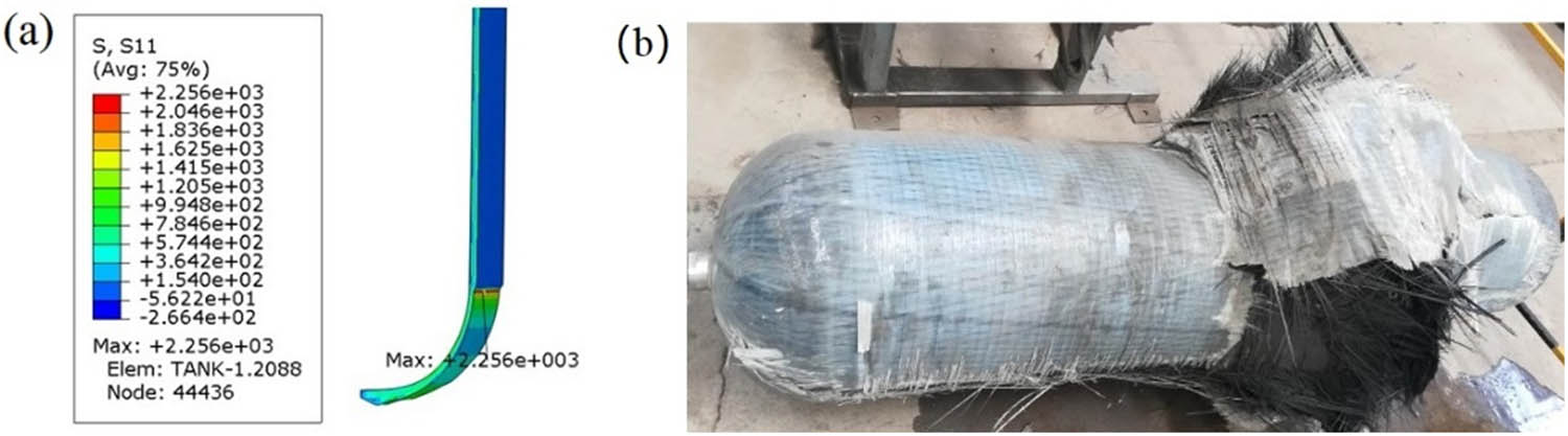
The failure mode of the type Ⅳ hydrogen storage vessel: (a) simulation and (b) experiment.
In the first part, to study the influence of the number of spiral winding layers, the 1/36 hydrogen storage vessel model is established. The winding angle is set as 10°, and a total of seven groups, namely 7, 14, 21, 28, 35, 42, and 50 layers, are set. Taking a seven-layer model as an example, after element-independent checking, the element number of the plastic liner is 14,364, and the element number of spiral wound layers is 24,990, as shown in Figure 3.
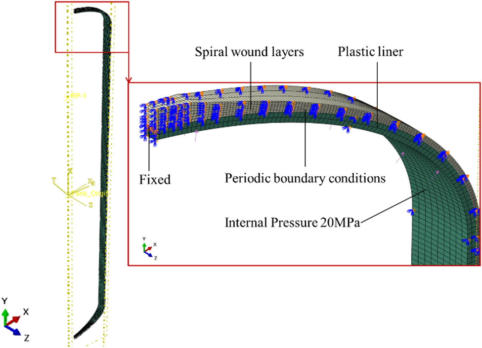
Mesh and boundary conditions of the 1/36 hydrogen storage vessel FE model.
In the second part, to study the influence of the number of circumferential wound layers, the 1/4 model is used for calculation convenience. Since the carrying capacity of the plastic liner can be ignored compared with the composite layers, only the carbon fiber circumferential wound layers are established for simulation. A total of 16 groups of circumferential winding method, namely, 5, 10, 15, 20, 25, 30, 35, 40, 45, 50, 55, 60, 65, 70, 75, and 80 layers, are analyzed. Taking a ten-layer model as an example, as shown in Figure 4, after element-independent checking, the FE model of circumferential wound layers is meshed by 5,270 elements.
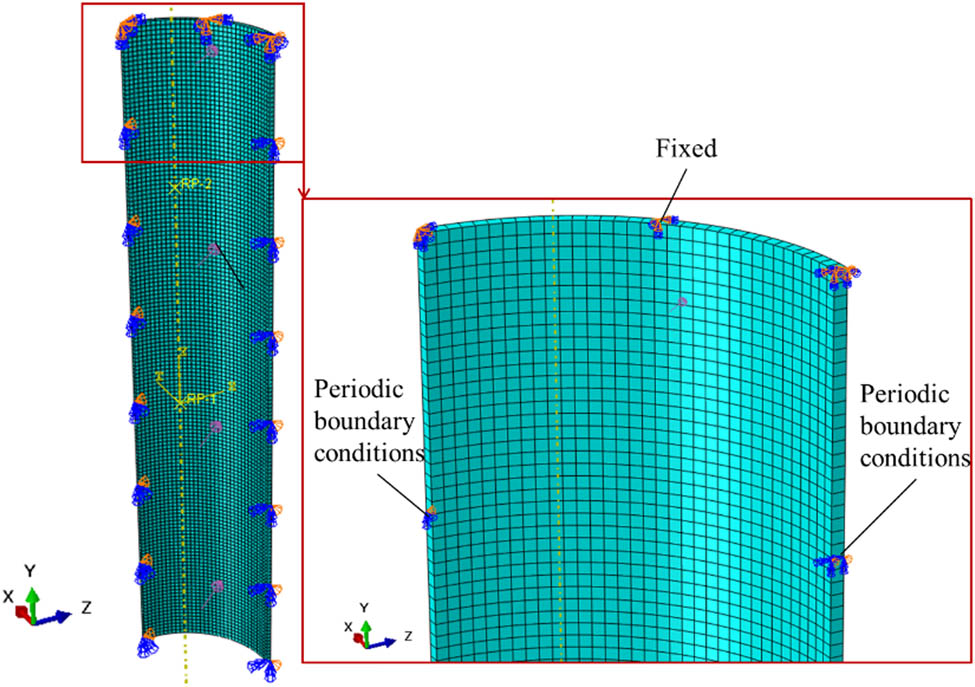
Mesh and boundary conditions of ten-layer circumferential winding layer FE model.
In the third part, to study the influence of different spiral winding angles, a total of 75 groups of spiral winding methods are studied. The winding angles are set as 10°, 15°, 20°, 25°, 30°, 35°, 40°, 45°, 50°, 55°, 60°, 65°, 70°, 75°, and 80°, and the number of winding layers are 7, 14, 21, 28, and 35. In this part, the modeling method and constraints are the same as those of the first part.
In the fourth part, the influence of different winding sequences of spiral and circumferential layers are studied. The modeling method and constraints are the same as those of the first part. The spiral winding angle is set as 50° here. A total of three groups of winding methods are carried out. The winding method of the first group is 14 layers of spiral winding inside and 21 layers of circumferential winding outside. The second group is 21 layers of circumferential winding inside and 14 layers of spiral winding outside. The third group is 7 layers of spiral winding inside and 21 layers of circumferential winding in the middle and 7 layers of spiral winding outside.
The applied internal pressure of the four simulations above is 20 MPa.
3 Results and discussion
3.1 Influence of the number of the spiral winding layers
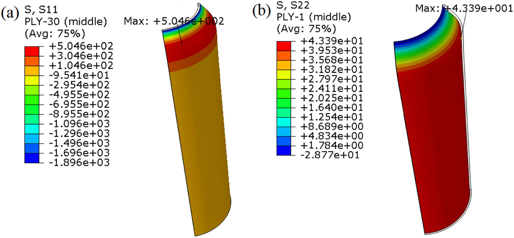
Taking the model of 28-layer spiral winding as an example, the stress along the fiber direction S11 and the stress perpendicular to the fiber direction S22 of the storage vessel are shown in Figures 5 and 6, respectively. It shows that the maximum stress S11 locates at the transition between the head and the cylinder, with the maximum value 975.9 MPa. Ignoring the stress at the fixed position, the maximum stress S22 occurs at the cylinder, with the maximum value of 45.9 MPa.
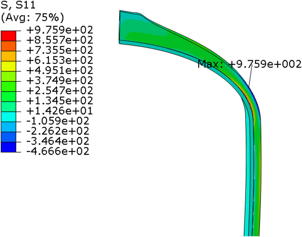
The stress along the fiber direction S11 of the 28-layer spiral winding model.
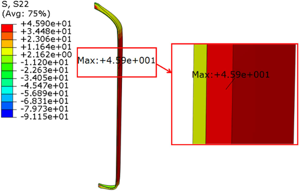
The stress perpendicular to the fiber direction S22 of the 28-layer spiral winding model.
Tables 3 and 4 show the stress analysis results of different numbers of spiral winding layers. It can be seen that, for all winding methods, the maximum S11 always appears at the transition between the head and the cylinder, and the maximum S22 always appears at the middle section of the cylinder.
Maximum value and position of S11 of different number of spiral winding layers
| Number of layers | Maximum S11 (MPa) | |
|---|---|---|
| Value | Position | |
| 7 | 2,169 | Transition between head and cylinder |
| 14 | 1,661 | Transition between head and cylinder |
| 21 | 1,261 | Transition between head and cylinder |
| 28 | 975.9 | Transition between head and cylinder |
| 35 | 781.3 | Transition between head and cylinder |
| 42 | 640.3 | Transition between head and cylinder |
| 50 | 548.1 | Transition between head and cylinder |
Maximum value and position of S22 of different number of spiral winding layers
| Number of layers | Maximum S22 (MPa) | |
|---|---|---|
| Value | Position | |
| 7 | 193.7 | Cylinder |
| 14 | 91.7 | Cylinder |
| 21 | 60.9 | Cylinder |
| 28 | 45.9 | Cylinder |
| 35 | 36.9 | Cylinder |
| 42 | 29.5 | Cylinder |
| 50 | 26.0 | Cylinder |
Figure 7 shows the maximum S11 and S22 variation curves with the number of spiral winding layers increasing. It is found that with the increase of the number of spiral winding layers, the stress along the fiber direction S11 and that perpendicular to the fiber direction S22 decrease gradually. At the beginning, the stress decreases greatly. When the number of winding layers reaches 35, the stress decreases more gently.
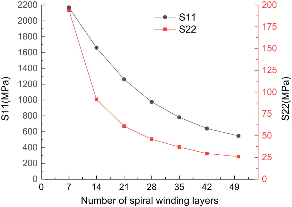
The maximum S11 and S22 variation curves with the number of spiral winding layers increasing.
The stress distribution along the thickness direction of the storage vessel is basically the same for different numbers of spiral winding layers, taking 28-layer spiral winding as an example. Figure 8 shows the S11 and S22 variation along the thickness direction of the 28-layer spiral winding. It shows that the maximum S11 appears at the innermost layer of the spiral winding layers. From the inside to the outside, the S11 first decreases and then increases. The turning point is in the middle of the spiral winding layers. The maximum S22 appears at the innermost layer of the spiral winding layers. It decreases from the inside to the outside layer by layer, but the stress change amplitude is small.
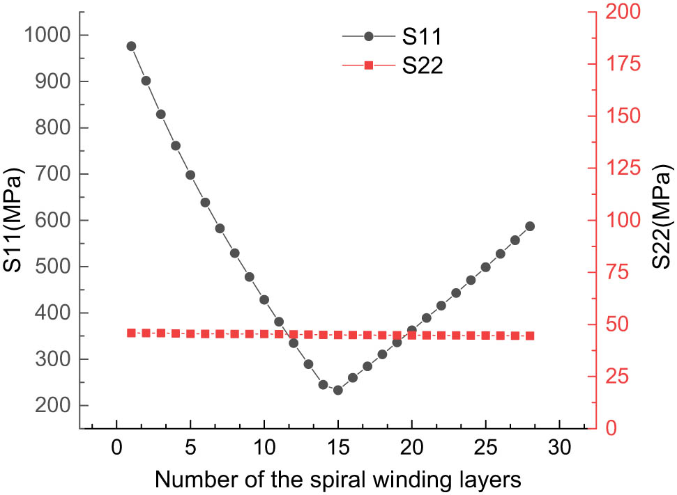
The S11 and S22 variation curves along the thickness direction of the 28-layer spiral winding.
3.2 Influence of the number of the circumferential winding layers
Taking the model of 30-layer circumferential winding as an example, the stress along the fiber direction S11 and the stress perpendicular to the fiber direction S22 of the storage vessel are shown in Figure 9. It can be seen that the maximum S11 is at the outermost of the circumferential winding layer, and the maximum S22 is at the innermost of the circumferential winding layer.
The stress contour of the 30-layer circumferential winding model: (a) S11 and (b) S22.
Table 5 shows the stress analysis results of different numbers of circumferential winding layers. It can be seen that for all of the circumferential winding methods, the maximum S11 appears at the outermost layer, and the maximum S22 appears at the innermost layer.
Stress analysis results of different numbers of circumferential winding layers
| Number of layers | Maximum S11 (MPa) | Maximum S22 (MPa) | ||
|---|---|---|---|---|
| Value | Position | Value | Position | |
| 5 | 2,607 | Outermost layer | 259.9 | Innermost layer |
| 10 | 1,431 | Outermost layer | 129.8 | Innermost layer |
| 15 | 976.1 | Outermost layer | 86.5 | Innermost layer |
| 20 | 743.6 | Outermost layer | 64.9 | Innermost layer |
| 25 | 601.6 | Outermost layer | 52.0 | Innermost layer |
| 30 | 504.6 | Outermost layer | 43.3 | Innermost layer |
| 35 | 433.7 | Outermost layer | 37.2 | Innermost layer |
| 40 | 379.1 | Outermost layer | 32.6 | Innermost layer |
| 45 | 336.3 | Outermost layer | 29.0 | Innermost layer |
| 50 | 305.2 | Outermost layer | 26.1 | Innermost layer |
| 55 | 277.3 | Outermost layer | 23.9 | Innermost layer |
| 60 | 255.4 | Outermost layer | 22.0 | Innermost layer |
| 65 | 236.1 | Outermost layer | 20.4 | Innermost layer |
| 70 | 220 | Outermost layer | 19.1 | Innermost layer |
| 75 | 206 | Outermost layer | 17.9 | Innermost layer |
| 80 | 193.7 | Outermost layer | 16.9 | Innermost layer |
Figure 10 shows the maximum S11 and S22 variation curves with the number of circumferential winding layers increasing. It is found that with the increase of the number of circumferential winding layers, the maximum S11 and maximum S22 decrease gradually. At the beginning, the stress decreases greatly. When the number of winding layers reaches 25, the stress decreases more gently.
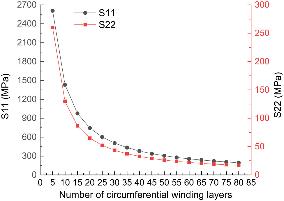
The maximum S11 and S22 variation curves with the number of circumferential winding layers increasing.
As the stress distribution is the same for different numbers of circumferential winding layers, take 30-layer circumferential winding as an example. Figure 11 shows the stress distribution along the thickness direction of a 30-layer circumferential winding model. It shows that the maximum S11 appears at the outermost layer. With the increase in the number of circumferential winding layers, the maximum S11 first keeps stable and then increases, and the turning point is at the middle layer. The maximum S22 appears at the innermost layer, and the change amplitude of S22 from inside to outside is small.
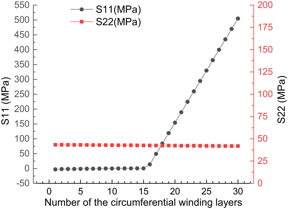
The S11 and S22 variation curve along the thickness direction of the 30-layer circumferential winding.
3.3 Influence of the spiral winding angles
Table 6 shows the stress analysis results of 28-layer models with different spiral winding angles. It can be seen that, with the increase of the winding angles, the position of the maximum S11 changes from the transition between the head and the cylinder to the middle section of the head, while the position of the maximum S22 changes from the cylinder to the middle section of the head.
The stress analysis results of 28-layer models with different spiral winding angles
| Winding angle (°) | Maximum S11 (MPa) | Maximum S22 (MPa) | ||
|---|---|---|---|---|
| Value | Position | Value | Position | |
| 10 | 975.9 | Transition between head and cylinder | 45.9 | Cylinder |
| 15 | 951.2 | Transition between head and cylinder | 45.8 | Cylinder |
| 20 | 917.1 | Transition between head and cylinder | 45.8 | Cylinder |
| 25 | 873.2 | Transition between head and cylinder | 45.8 | Cylinder |
| 30 | 819.4 | Transition between head and cylinder | 46.4 | Cylinder |
| 35 | 755.6 | Transition between head and cylinder | 47.2 | Cylinder |
| 40 | 682.7 | Transition between head and cylinder | 47.8 | Cylinder |
| 45 | 603.6 | Transition between head and cylinder | 48.3 | Cylinder |
| 50 | 523.6 | Transition between head and cylinder | 48.3 | Cylinder |
| 55 | 450.6 | Transition between head and cylinder | 47.8 | Cylinder |
| 60 | 397 | Transition between head and cylinder | 50.9 | Middle of head |
| 65 | 349.9 | Transition between head and cylinder | 59.8 | Middle of head |
| 70 | 347.9 | Middle of head | 70.7 | Middle of head |
| 75 | 407.9 | Middle of head | 73.7 | Middle of head |
| 80 | 539.8 | Middle of head | 103.9 | Middle of head |
Figure 12 shows the maximum S11 and S22 variation with the increase of the spiral winding angle under different numbers of layers. For all of the number of winding layers, with the increase in the winding angle, the maximum S11 decreases first and then increases, but the turning point gradually changes from 60° to 70°. With the increase in the spiral winding angle, the maximum S22 stabilizes first and then increases. With the number of winding layers increasing, the turning point gradually changes from 70° to 55°.
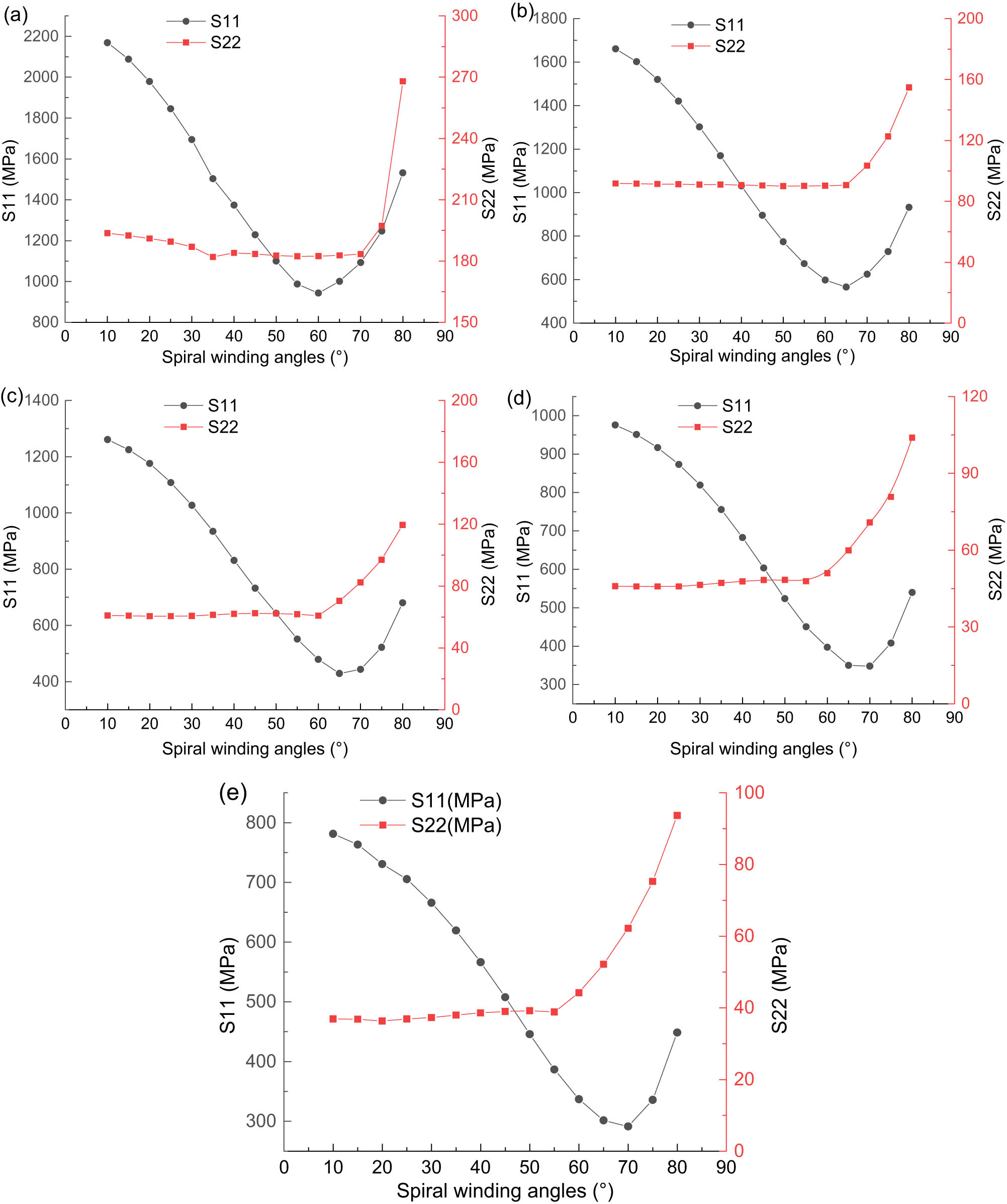
The maximum S11 and S22 variation with the increase of the spiral winding angle: (a) 7-layer winding model, (b) 14-layer winding model, (c) 21-layer winding model, (d) 28-layer winding model, and (e) 35-layer winding model.
3.4 Influence of different winding sequences
The stress analysis results of the three winding methods are summarized in Tables 7 and 8. Table 7 lists the maximum S11 and S22 of the spiral winding layers. It shows that, for the three winding sequences, the maximum S11 always appears at the transition between the head and the cylinder, and the maximum S22 always appears at the middle section of the head. Table 8 lists the maximum S11 and S22 of the circumferential winding layers. For the winding method of 21-layer circumferential winding + 14-layer spiral winding, the maximum S11 appears at the cylinder, while that of the other two winding methods appear at the end of the cylinder. The maximum S22 all appears at the cylinder. Comparing the stress results of the three winding sequences, the S11 and S22 of the method with 21-layer circumferential winding + 14-layer spiral winding are the smallest. It will be seen that performing circumferential winding inside and then spiral winding outside is the best winding sequence.
Stress analysis results of spiral winding
| Winding sequence | Spiral winding layers | |||
|---|---|---|---|---|
| Maximum S11 (MPa) | Position | Maximum S22 (MPa) | Position | |
| 14 + 21 | 753.9 | Transition between head and cylinder | 57.5 | Middle section of head |
| 21 + 14 | 713.8 | Transition between head and cylinder | 56.5 | Middle section of head |
| 7 + 21 + 7 | 717.1 | Transition between head and cylinder | 57.0 | Middle section of head |
Stress analysis results of circumferential winding
| Winding sequence | Circumferential winding layers | |||
|---|---|---|---|---|
| Maximum S11 (MPa) | Position | Maximum S22 (MPa) | Position | |
| 14 + 21 | 238.3 | End of cylinder | 40.5 | Cylinder |
| 21 + 14 | 85.8 | Cylinder | 36.8 | Cylinder |
| 7 + 21 + 7 | 115.8 | End of cylinder | 40.0 | Cylinder |
3.5 Discussion
According to the previous analysis, with the increase in the number of spiral winding layers, the maximum S11 and maximum S22 decrease quickly first. But when the number of winding layers reaches about 35, the stress decreases significantly slowly. Besides, with the increase in the number of circumferential winding layers, the maximum S11 and maximum S22 decrease quickly first. But when the number of winding layers reaches about 25, the stress decreases significantly slowly. It indicates that it is better if the number of spiral winding layers and the number of circumferential winding layers are not the more. When the number of winding layers exceeds a certain value, the bearing capacity of the storage vessel will not be improved significantly, but the manufacturing cost will increase.
According to the 75 groups of winding methods with different winding layers and different winding angles, it is found that with the increase of the winding angles, the maximum S11 decreases first and then increases, while the maximum S22 stabilizes first and then increases. For different numbers of winding layers, the turning point of stress rise is different. Considering the values of maximum S11 and maximum S22, the best winding angle is between 55° and 65°. The simulations of different composite material laying parameters provide a certain foundation for the production, manufacturing, and structural optimization of hydrogen storage vessel.
4 Conclusions
The influence of composite material laying parameters on the load-carrying capacity of Ⅳ-type hydrogen storage vessel was investigated, and the following conclusions can be obtained.
The number of winding layers is not the more the better, there is an optimal number of winding layers. The best spiral winding angle is between 55° and 65°. Performing circumferential winding layers inside and spiral winding layers outside is the best winding sequence.
With the increase of the number of the spiral and circumferential winding layers, both of the maximum stress along the fiber direction S11 and perpendicular to the fiber direction S22 decrease gradually. But, for spiral winding layers, the maximum S11 and S22 appears at the innermost layer, while the maximum S11 occurs at the outermost layer and the maximum S22 occurs at the innermost layer for the circumferential winding layers.
When the number of spiral winding layers and the number of circumferential winding layers exceed 35 and 25, respectively, the bearing capacity of the storage vessel is not significantly improved.
With the increase in the spiral winding angles, the maximum S11 decreases first and then increases, while the maximum S22 is stable first and then increases. But, for different numbers of winding layers, the turning point of stress rise is different.
Acknowledgments
The study was supported by the National Natural Science Foundation of China (52205175), Taishan Scholar Foundation for Young People of Shandong Province (tsqnz20240827), the Natural Science Foundation of Shandong Province (ZR2021QE099), the Key R&D Program of Shandong Province (2021CXGC011302), and Science & Technology Support Project for Young People in Colleges of Shandong Province (2023KJ120).
-
Funding information: The authors state no funding involved.
-
Author contributions: All authors have accepted responsibility for the entire content of this manuscript and consented to its submission to the journal, reviewed all the results, and approved the final version of the manuscript. QZ: methodology, logical structure; WJ: software, validation; JY: data curation, writing-original draft preparation; JB: writing – reviewing and editing; HF: experiments, data analysis of the experiment; BW: investigation and analysis of the influence law.
-
Conflict of interest: Authors J.B. and H.F. are employees of Shandong Auyan New Energy Technology Co., Ltd. The authors declare no other conflict of interest.
-
Data availability statement: The datasets generated during and/or analyzed during the current study are available from the corresponding author on reasonable request.
References
[1] Park C, Lim S, Shin J, Lee CY. How much hydrogen should be supplied in the transportation market? Focusing on hydrogen fuel cell vehicle demand in South Korea: Hydrogen demand and fuel cell vehicles in South Korea. Technol Forecast Soc. 2022;181:121750.10.1016/j.techfore.2022.121750Search in Google Scholar
[2] Nguyen BN, Roh HS, Merkel DR, Simmons KL. A predictive modeling tool for damage analysis and design of hydrogen storage composite pressure vessels. Int J Hydrogen Energy. 2021;46:20573–85.10.1016/j.ijhydene.2021.03.139Search in Google Scholar
[3] Zhou W, Wang J, Pan ZB, Liu J, Ma LH, Zhou JY, et al. Review on optimization design, failure analysis and non-destructive testing of composite hydrogen storage vessel. Int J Hydrogen Energy. 2022;47:38862–83.10.1016/j.ijhydene.2022.09.028Search in Google Scholar
[4] Greene DL, Ogden JM, Lin ZH. Challenges in the designing, planning and deployment of hydrogen refueling infrastructure for fuel cell electric vehicles. Transporatation. 2020;6:100086.10.1016/j.etran.2020.100086Search in Google Scholar
[5] Usman MR. Hydrogen storage methods: Review and current status. Renew Sustainable Energ Rev. 2022;167:112743.10.1016/j.rser.2022.112743Search in Google Scholar
[6] Barthelemy H, Weber M, Barbier F. Hydrogen storage: Recent improvements and industrial perspectives. Int J Hydrogen Energy. 2016;42(11):7254–62.10.1016/j.ijhydene.2016.03.178Search in Google Scholar
[7] Moradi R, Groth KM. Hydrogen storage and delivery: Review of the state of the art technologies and risk and reliability analysis. Int J Hydrogen Energy. 2019;44(23):12254–69.10.1016/j.ijhydene.2019.03.041Search in Google Scholar
[8] Lee Y, Park ET, Jeong J, Shi H, Kim J, Kang BS, et al. Weight optimization of hydrogen storage vessels for quadcopter UAV using genetic algorithm. Int J Hydrogen Energy. 2020;45(58):33939–47.10.1016/j.ijhydene.2020.09.014Search in Google Scholar
[9] Zhang Q, Xu H, Jia XL, Zu L, Cheng S, Wang HB. Design of a 70 MPa type IV hydrogen storage vessel using accurate modeling techniques for dome thickness prediction. Compos Struct. 2020;236:111915.10.1016/j.compstruct.2020.111915Search in Google Scholar
[10] Zhao XH, Yan Y, Zhang JQ, Zhang F, Wang Z, Ni ZH. Analysis of multilayered carbon fiber winding of cryo-compressed hydrogen storage vessel. Int J Hydrogen Energy. 2022;47(20):10934–46.10.1016/j.ijhydene.2022.01.136Search in Google Scholar
[11] Rivard E, Trudeau M, Zaghib K. Hydrogen storage for mobility: a review. Materials. 2019;12:1973.10.3390/ma12121973Search in Google Scholar PubMed PubMed Central
[12] Zhang Q, Liu JL, Jiang WC. Tensile fatigue behaviour and life distribution model of the pultruded fibre reinforced composites. Polym Polym Compos. 2022;30:1–11.10.1177/09673911221083775Search in Google Scholar
[13] Echtermeyer AT, Lasn K. Safety approach for composite pressure vessels for road transport of hydrogen. Part 2: Safety factors and test requirements. Int J Hydrogen Energ. 2014;39(26):14142–52.10.1016/j.ijhydene.2014.06.016Search in Google Scholar
[14] Hu ZY, Chen MH, Zu L, Jia XL, Shen AL, Yang Q, et al. Investigation on failure behaviors of 70MPa Type IV carbon fiber overwound hydrogen storage vessels. Compos Struct. 2021;259:113387.10.1016/j.compstruct.2020.113387Search in Google Scholar
[15] Irisarri FX, Bassir DH, Carrere N, Maire JF. Multi-objective stackingsequence optimization for laminated composite structures. Compos Sci Technol. 2009;69(7-8):983–90.10.1016/j.compscitech.2009.01.011Search in Google Scholar
[16] Aydin L, Aydın O, Artem HS, Mert A. Design of dimensionally stable composites using efficient global optimization method. J Mater Des Appl. 2016;233(2):1–13.10.1177/1464420716664921Search in Google Scholar
[17] Pelletier J, Vel S. Multi-objective optimization of fiber rein-forced composite laminates for strength, stiffness and mini-mal mass. Comput Struct. 2006;84(29):2065–80.10.1016/j.compstruc.2006.06.001Search in Google Scholar
[18] Zaami A, Baran I, Bor TC, Akkerman R. New process optimization framework for laser assisted tape winding of composite pressure vessels: controlling the unsteady bonding temperature. Mater Des. 2020;196:109130.10.1016/j.matdes.2020.109130Search in Google Scholar
[19] Park JS, Hong CS, Kim CG, Kim CU. Analysis of filament wound composite structures considering the change of winding angles through the thickness direction. Compos Struct. 2002;55(1):63–71.10.1016/S0263-8223(01)00137-4Search in Google Scholar
[20] Rosenow MWK. Wind angle effects in glass fiber-reinforced polyester filament wound pipes. Compos. 1984;15(2):144–52.10.1016/0010-4361(84)90727-4Search in Google Scholar
[21] Kim CU, Hong CS, Kim CG, Kim JY. Optimal design of filament wound type 3 tanks under internal pressure using a modified genetic algorithm. Compos Struct. 2004;71(1):16–25.10.1016/j.compstruct.2004.09.006Search in Google Scholar
[22] Hu ZY, Chen MH, Pan B. Simulation and burst validation of 70 MPa type IV hydrogen storage vessel with dome reinforcement. Int J Hydrogen Energy. 2021;46(46):23779–94.10.1016/j.ijhydene.2021.04.186Search in Google Scholar
[23] Si XC, Qi XQ, Wang HC, Chen QL. Influence of winding angle on key properties of fiberglass wound tubes for composite insulators. Henan Sci Tech. 2021;40(9):34–6.Search in Google Scholar
[24] Ramirez JPB, Halm D, Grandidier JC, Villalonga S, Nony F. 700 bar type IV high pressure hydrogen storage vessel burst-Simulation and experimental validation. Int J Hydrogen Energy. 2015;40(38):13183–92.10.1016/j.ijhydene.2015.05.126Search in Google Scholar
[25] Sharma P, Bera T, Semwal K, Badhe RM, Sharma A, Ramakumar SSV, et al. Theoretical analysis of design of filament wound type 3 composite cylinder for the storage of compressed hydrogen gas. Int J Hydrogen Energy. 2020;45(46):25386–97.10.1016/j.ijhydene.2020.06.269Search in Google Scholar
© 2024 the author(s), published by De Gruyter
This work is licensed under the Creative Commons Attribution 4.0 International License.
Articles in the same Issue
- Regular Articles
- Research on damage evolution mechanisms under compressive and tensile tests of plain weave SiCf/SiC composites using in situ X-ray CT
- Structural optimization of trays in bolt support systems
- Continuum percolation of the realistic nonuniform ITZs in 3D polyphase concrete systems involving the aggregate shape and size differentiation
- Multiscale water diffusivity prediction of plain woven composites considering void defects
- The application of epoxy resin polymers by laser induction technologies
- Analysis of water absorption on the efficiency of bonded composite repair of aluminum alloy panels
- Experimental research on bonding mechanical performance of the interface between cementitious layers
- A study on the effect of microspheres on the freeze–thaw resistance of EPS concrete
- Influence of Ti2SnC content on arc erosion resistance in Ag–Ti2SnC composites
- Cement-based composites with ZIF-8@TiO2-coated activated carbon fiber for efficient removal of formaldehyde
- Microstructure and chloride transport of aeolian sand concrete under long-term natural immersion
- Simulation study on basic road performance and modification mechanism of red mud modified asphalt mixture
- Extraction and characterization of nano-silica particles to enhance mechanical properties of general-purpose unsaturated polyester resin
- Roles of corn starch and gellan gum in changing of unconfined compressive strength of Shanghai alluvial clay
- A review on innovative approaches to expansive soil stabilization: Focussing on EPS beads, sand, and jute
- Experimental investigation of the performances of thick CFRP, GFRP, and KFRP composite plates under ballistic impact
- Preparation and characterization of titanium gypsum artificial aggregate
- Characteristics of bulletproof plate made from silkworm cocoon waste: Hybrid silkworm cocoon waste-reinforced epoxy/UHMWPE composite
- Experimental research on influence of curing environment on mechanical properties of coal gangue cementation
- Multi-objective optimization of machining variables for wire-EDM of LM6/fly ash composite materials using grey relational analysis
- Synthesis and characterization of Ag@Ni co-axial nanocables and their fluorescent and catalytic properties
- Beneficial effect of 4% Ta addition on the corrosion mitigation of Ti–12% Zr alloy after different immersion times in 3.5% NaCl solutions
- Study on electrical conductive mechanism of mayenite derivative C12A7:C
- Fast prediction of concrete equivalent modulus based on the random aggregate model and image quadtree SBFEM
- Research on uniaxial compression performance and constitutive relationship of RBP-UHPC after high temperature
- Experimental analysis of frost resistance and failure models in engineered cementitious composites with the integration of Yellow River sand
- Influence of tin additions on the corrosion passivation of TiZrTa alloy in sodium chloride solutions
- Microstructure and finite element analysis of Mo2C-diamond/Cu composites by spark plasma sintering
- Low-velocity impact response optimization of the foam-cored sandwich panels with CFRP skins for electric aircraft fuselage skin application
- Research on the carbonation resistance and improvement technology of fully recycled aggregate concrete
- Study on the basic properties of iron tailings powder-desulfurization ash mine filling cementitious material
- Preparation and mechanical properties of the 2.5D carbon glass hybrid woven composite materials
- Improvement on interfacial properties of CuW and CuCr bimetallic materials with high-entropy alloy interlayers via infiltration method
- Investigation properties of ultra-high performance concrete incorporating pond ash
- Effects of binder paste-to-aggregate ratio and polypropylene fiber content on the performance of high-flowability steel fiber-reinforced concrete for slab/deck overlays
- Interfacial bonding characteristics of multi-walled carbon nanotube/ultralight foamed concrete
- Classification of damping properties of fabric-reinforced flat beam-like specimens by a degree of ondulation implying a mesomechanic kinematic
- Influence of mica paper surface modification on the water resistance of mica paper/organic silicone resin composites
- Impact of cooling methods on the corrosion behavior of AA6063 aluminum alloy in a chloride solution
- Wear mechanism analysis of internal chip removal drill for CFRP drilling
- Investigation on acoustic properties of metal hollow sphere A356 aluminum matrix composites
- Uniaxial compression stress–strain relationship of fully aeolian sand concrete at low temperatures
- Experimental study on the influence of aggregate morphology on concrete interfacial properties
- Intelligent sportswear design: Innovative applications based on conjugated nanomaterials
- Research on the equivalent stretching mechanical properties of Nomex honeycomb core considering the effect of resin coating
- Numerical analysis and experimental research on the vibration performance of concrete vibration table in PC components
- Assessment of mechanical and biological properties of Ti–31Nb–7.7Zr alloy for spinal surgery implant
- Theoretical research on load distribution of composite pre-tightened teeth connections embedded with soft layers
- Coupling design features of material surface treatment for ceramic products based on ResNet
- Optimizing superelastic shape-memory alloy fibers for enhancing the pullout performance in engineered cementitious composites
- Multi-scale finite element simulation of needle-punched quartz fiber reinforced composites
- Thermo-mechanical coupling behavior of needle-punched carbon/carbon composites
- Influence of composite material laying parameters on the load-carrying capacity of type IV hydrogen storage vessel
- Review Articles
- Effect of carbon nanotubes on mechanical properties of aluminum matrix composites: A review
- On in-house developed feedstock filament of polymer and polymeric composites and their recycling process – A comprehensive review
- Research progress on freeze–thaw constitutive model of concrete based on damage mechanics
- A bibliometric and content analysis of research trends in paver blocks: Mapping the scientific landscape
- Bibliometric analysis of stone column research trends: A Web of Science perspective