Research on uniaxial compression performance and constitutive relationship of RBP-UHPC after high temperature
-


Abstract
This study examines the impact of the recycled brick powder (RBP) replacement rate, especially at elevated temperatures on RBP-ultra-high-performance concrete (UHPC) properties such as the stress–strain curve, Poisson’s ratio, elastic modulus, and axial compressive strength through uniaxial compression experiments. The results show that with the increase of heating temperature, the axial compressive strength of the specimen increases first and then decreases under natural cooling (NC). In contrast, Poisson’s ratio shows opposite values. The peak strain continues to increase, and the initial elastic modulus and peak secant modulus continue to decrease. Compared with NC, the axial compressive strength of the specimens under water cooling has been reduced, the peak strain is generally larger, the initial elastic modulus and the peak secant modulus are smaller, and the incorporation of RBP also has a certain effect on the mechanical properties. Through regression analysis, an equation is established to calculate the axial compressive strength of RBP-UHPC with temperature, accounting for variables such as temperature, RBP replacement rate, and cooling method. Furthermore, based on the results of axial compression experiments, a constitutive equation for axial compression in RBP-UHPC after exposure to high temperatures is proposed. Overall, the theoretical curve closely aligns with the experimental curve, verifying its accuracy.
1 Introduction
Since its inception in 1994 [1], ultra-high-performance concrete (UHPC) has attracted increasing attention in both academia and engineering circles. Unlike ordinary concrete, UHPC primarily comprises cement, water, fine aggregate, fine steel fibers, and admixtures. Its exceptionally low water–binder ratio results in remarkable homogeneity and compactness, defining it as a cement-based composite material with superior compressive strength, tensile strength, and durability compared to high-performance concrete (HPC) [2,3,4,5]. UHPC is widely used in high-rise buildings, long-span bridges, protective fortifications, prefabricated buildings, and other important civil engineering structures [6,7,8], marking it as a pivotal direction for future concrete technology development. With the increase in market demand, its commercial production has begun to appear in many countries, such as Australia, China, South Korea, and the United States [9].
The extremely low water–binder ratio of UHPC leads to a high amount of cement. However, the production of UHPC typically involves a high cement content, with only 30–35% of the cement participating in the hydration reaction, while the remainder serves a filling role [10], which violates the concept of green development in the construction industry. According to statistics, the annual output of cement globally reached about 4.1 billion tons in 2019 [11], and China’s cement production share accounted for 56.1% of the world’s top ten major cement producers [12]. The cement production process has the remarkable characteristics of high energy consumption and high carbon emissions [13,14]. In efforts to mitigate cement consumption and reduce carbon emissions during UHPC production, scholars have explored the use of various industrial solid wastes as partial cement replacements to modify concrete properties [15,16]. With the rapid development of urbanization in China, the amount of construction solid waste produced each year is as high as 1.8 billion tons [17]. Wild et al. [18] studied the characteristics of volcanic ash in the clay brick in the construction solid waste through experiments. The chemical composition of the recycled brick powder (RBP) obtained by crushing and screening also meets the standard requirements of volcanic ash materials [19]. Yuan et al. [20] demonstrated that in UHPC, incorporating RBP resulted in compressive strength exceeding 140 MPa at 28 days, with flexural toughness and tensile strain peaking at 40 and 30% replacement rates, respectively. The maximum bond strength between steel fiber and matrix was also observed at a 40% substitution rate. Furthermore, Zhang et al. [21] reinforced ordinary C50 concrete with UHPC containing RBP, improving bonding strength and frost resistance. Their study established a bonding model, showing enhanced interfacial performance and durability for damaged concrete in cold regions. Therefore, it has the possibility of partially replacing cement to make concrete materials, and because the clay brick is calcined at high temperatures, it also shows good high temperature resistance. If it can be used on a large scale, it will greatly reduce the burden of construction solid waste and provide a new path for recycling construction solid waste [22].
However, under the high temperature conditions, according to the thermal stress theory and void pressure theory [23,24,25], the internal steam of UHPC will overflow and be blocked due to its dense microstructure, resulting in bursting and spalling [26,27,28]. High temperature will decompose calcium hydroxide (CH) [29], hydrated calcium silicate (C–S–H), and other substances in the hydration products, resulting in a decrease in material strength [30]. In recent years, scholars have proposed a series of measures to improve the high temperature spalling of UHPC [31], such as adding PP fiber and steel fiber. The residual pores of PP fiber after high temperature melting can alleviate the internal steam pressure, and steel fiber has excellent crack resistance [32,33]. The incorporation of fiber can improve the spalling of UHPC after high temperature [34,35] and mechanical properties [36,37]. However, the application of UHPC in structural elements necessitates consideration of its performance under extreme conditions, particularly high temperatures. HPC, a close relative of UHPC, is frequently employed in civil and hydraulic engineering structures where durability is paramount. The risk of extreme fire incidents poses a significant concern for HPC structures. To address this, comprehensive studies are conducted to evaluate the mechanical properties of HPC after exposure to high temperatures and rapid cooling [38]. In a computational study, Dimitri et al. [39] explored the bond behavior of FRP laminates on concrete under thermal and high-temperature conditions. This research provides insights into adhesive model development for engineering design, particularly in high-temperature environments.
In addition, the selection of specific aggregates [40], such as basalt and limestone, or the use of reasonable curing methods [41,42], or used calcium aluminate cement which is more resistant to high temperatures than Portland cement [31], can also improve the high-temperature performance of UHPC, as it is commonly used in key parts of building structures [43].
This study aims to investigate the impact of incorporating RBP on the high-temperature performance of UHPC. The significance of this research is that it plays an important role by analyzing the stress–strain behavior of UHPC containing RBP after exposure to elevated temperatures. This study aims to investigate the impact of incorporating RBP on the high-temperature performance of UHPC. Analyzing the stress–strain behavior of UHPC containing RBP after exposure to elevated temperatures, we aim to establish a uniaxial compression constitutive equation for UHPC with RBP post-high-temperature exposure. This study involves uniaxial compression experiments on UHPC prism specimens containing RBP after exposure to elevated temperatures. The influence of the replacement rate of RBP and the target temperature on the stress–strain curve of UHPC with RBP after high temperature is examined, and the segmented uniaxial compression constitutive equation of UHPC with RBP after high temperature is established.
2 Experimental design
2.1 Raw materials and mix proportion
The experiment utilized P.O 52.5 ordinary Portland cement, the main technical indicators of which are shown in Table 1. The admixture included fly ash and silica ash. The main components of fly ash are 54.76% SiO2 and 24.56% Al2O3, and silica ash is containing 96.32% SiO2. RBP was sourced from the waste sintered clay brick produced by urban demolition. The waste-sintered bricks were crushed and then sieved to obtain RBP with a particle size of less than 0.075 mm. The RBP with the highest activity index used in the test was obtained by ball milling 45 min excitation method [44]. It featured a specific surface area of 600 m2 kg−1, moisture content below 0.50%, and its key technical properties are listed in Table 2. Fine aggregate consisted of natural river sand from Henan Province, with particle sizes ranging from 0.075 to 1.25 mm, mud content below 0.5%, and no mud blocks meeting the specified requirements [45]; particle size distribution is shown in Table 3. The fiber is copper-plated micro steel fiber, with a length of 12.0 mm and a diameter of 0.2 mm, which is employed as reinforcement, with pertinent technical details available in Table 4. The CQJ-JSS-type polycarboxylate superplasticizer was used as the admixture, and the water reduction rate was 32%. The mixing and curing water were ordinary tap water.
Main technical indexes of cement
| Specific surface area (m2 kg−1) | Stability | SO3 (%) | Cl− (%) | MgO (%) | Ignition loss (%) | Setting time (min) | 28-day strength (MPa) | ||
|---|---|---|---|---|---|---|---|---|---|
| Initial set | Final set | Flexural strength | Compressive strength | ||||||
| 387 | Qualification | 2.33 | 0.027 | 3.12 | 2.36 | 165 | 204 | 9.0 | 62.8 |
Main indexes and components of RBP
| Specific surface area (m2 kg−1) | Moisture content (%) | Major contents of components (%) | |||||
|---|---|---|---|---|---|---|---|
| SiO2 | Al2O3 | Fe2O3 | CaO | MgO | Na2O | ||
| 600 | ≦0.50 | 68.15 | 16.51 | 7.20 | 1.80 | 0.94 | 0.65 |
Particle size distribution of river sand
| Grain size (mm) | <0.075 | 0.075–0.17 | 0.17–0.315 | 0.315–0.63 | 0.63–1.25 | >1.25 |
|---|---|---|---|---|---|---|
| Content (%) | 0.67 | 3.37 | 10.00 | 36.12 | 45.35 | 4.49 |
Main technical indexes of steel fiber
| Length (mm) | Diameter (mm) | Density (g cm−3) | Form | Tensile strength (MPa) |
|---|---|---|---|---|
| 12.0 | 0.2 | 7.8 | Formed straight and smooth | >2,000.0 |
Based on the relevant literature [46] and the previous trial, the UHPC benchmark mix ratio (RBP-0) was obtained. The processed RBP was partially replaced by cement to prepare RBP-UHPC, with replacement rates of 0, 30, and 50%, and mix proportions are shown in Table 5. In this study, NC represents the specimen with natural cooling, and WC represents the specimen with water cooling. For example, RBP-30-WC indicates that the replacement rate of RBP is 30% and the specimen is WC.
Mix proportion of RBP-UHPC (kg m−3)
| Group | Replacement rate (%) | Cement | RBP | Fly ash | Silica ash | River sand | Steel fiber | Water reducing admixture | Water |
|---|---|---|---|---|---|---|---|---|---|
| RBP-0 | 0 | 700 | 0 | 100 | 200 | 1,000 | 156 | 30 | 170 |
| RBP-30 | 30 | 490 | 210 | 100 | 200 | 1,000 | 156 | 30 | 170 |
| RBP-50 | 50 | 350 | 350 | 100 | 200 | 1,000 | 156 | 30 | 170 |
The specimens were prepared by a horizontal concrete forced mixer. A total of 27 sets of prism specimens (100 mm × 100 mm × 300 mm) with three specimens in each group were prepared according to 0, 30, and 50% RBP replacement rates, five kinds of temperature gradients (25, 200, 400, 600, and 800°C), and two kinds of cooling methods (NC and WC). After the pouring is completed, the specimen is placed for 1–2 days, then the formwork is removed and then put into the steam rapid curing box, and the temperature is raised to 90°C at a rate of 15°C/h, and the constant temperature is maintained for 48 h, and then the temperature is reduced to room temperature at a cooling rate of 15°C/h. After steam curing, the specimens were placed in a standard curing chamber until the specified age.
2.2 High-temperature test
The high-temperature testing was conducted utilizing a box-type resistance furnace, capable of achieving a maximum heating rate of 10°C/min and a maximum operating temperature of up to 1,200°C. Prior to initiating heating, the heating rate was initially set to 3°C/min, and the specimens were held at this temperature for 1 h, as illustrated in the heating curve depicted in Figure 1. After completing the heating process, specimens designated for NC were allowed to remain within the furnace for cooling. Conversely, those specimens requiring WC were promptly removed from the furnace and placed into pre-prepared water tanks. Real-time monitoring of water temperature changes in the tanks was performed, and the cooling process was considered complete when the water temperature reached stability without further fluctuations.

Heating curve.
2.3 Experimental method
According to the principle of Saint-Venant, the area within 100 mm height in the middle of the specimen should be selected as the vertical deformation measurement area in the experiment, and the vertical compression deformation can be measured by installing a displacement meter at this position. At the same time, the vertical and transverse 8 cm concrete strain gauges are pasted at the center of the two sides perpendicular to the pouring surface of the specimen, and the vertical deformation and transverse deformation of the specimen under vertical load are measured to calculate Poisson’s ratio. Computer software records the above displacement and strain values in real-time. The YAW-3000 electro-hydraulic pressure testing machine was used for uniaxial compression loading, as shown in Figure 2. Preloading was performed before formal loading, and the preload was loaded at a speed of 2 kN s−1 until the specimen was unloaded at 20% of the estimated peak load. The load control loading with a loading speed of 5 kN s−1 was used in the formal loading, and the loading was switched to displacement loading until the specimen was destroyed until about 70% of the expected peak load was loaded. At this time, the loading speed was 0.005 mm s−1. Some specimens have too much compression after high temperatures, which leads to too long experiment time. The experiment can be stopped manually when the load drops to about 30% of the peak load and the machine automatically measures and records the vertical load borne by the specimen.

Loading procedure of axial compression specimens.
3 Uniaxial compression experimental analysis of RBP-UHPC after high temperature
3.1 Full stress–strain curve
The whole process of the load–displacement numerical value of the specimen is analyzed and processed. The full stress–strain curve of the specimen under uniaxial compression can be obtained by the calculation of Equations (1) and (2), as shown in Figure 3.
where σ is the stress of the specimen (MPa); ε is the strain of the specimen; N is the axial load (kN) of the specimen; A is the cross-sectional area (mm2) of the specimen; l is the gauge distance of the specimen, that is, the distance between the upper and lower measuring points of the displacement meter is 100 mm; and Δl is the axial compressive deformation (mm) value of concrete within the specimen gauge.

Uniaxial compression stress–strain curve of RBP-UHPC after high temperature: (a) RBP-0-NC, (b) RBP-0-WC, (c) RBP-30-NC, (d) RBP-30-WC, (e) RBP-50-NC, and (f) RBP-50-WC.
From Figure 3, it can be seen that the stress–strain curve change process of each group of RBP-UHPC specimens is generally similar. First, it is the elastic stage in which the ascending curve is a straight line; with the increase of load, the specimen slowly enters the elastic–plastic stage, and the curve begins to slow down gradually. When the specimen reaches the peak point, the loading continues, and the bearing capacity of the specimen gradually decreases until the failure of the specimen. Through observation, it can be found that the stress–strain curve shows an obvious convex curve, and the rising part of the curve has the same regularity. However, due to the different temperatures, RBP replacement rate, and cooling method of each group of specimens, variations in the trend of the curve are also different.
When the temperature is below 600°C, the initial slope of the curve decreases as the replacement rate increases. However, when the temperature is 600°C or higher, the initial slope of the curve initially increases, then decreases with increasing replacement rate. The area enclosed by the stress–strain curve and the coordinate axis increases with the increase of the RBP replacement rate, which indicates that UHPC with more RBP replacement rate has better ductility and toughness. When the action temperature is less than or equal to 600°C, the RBP-30 mix shows the highest axial compressive strength and peak strain. At 800°C, the axial compressive strength increases with the increase of the replacement rate. Compared with WC, under the same replacement rate and heating temperature, the axial compression strength of the specimens under NC is higher, but the peak strain is lowest.
During NC, when the action temperature is less than 400°C, the peak load of the specimens with different RBP replacement rates gradually increases. When the action temperature is greater than or equal to 400°C, the peak load of the specimens with different RBP replacement rates gradually decreases. In the case of WC, as temperature increases, the peak point of each specimen group gradually moves to the lower right, and the descending section of the final curve gradually tends to be interlaced. The above reasons may be that after high temperature, the corrosion and expansion of steel fibers in UHPC specimens and the decomposition of hydration products lead to cracks on the surface of UHPC (WC further aggravates the damage of matrix), which is caused by the different crack propagation rates of each specimen [47].
3.2 Axial compressive strength
Figure 4 shows the change curve of axial compressive strength of RBP-UHPC after high temperature, and Figure 5 shows the change of relative value (f cT/f c) of axial compressive strength of RBP-UHPC with replacement rates of RBP.

Change curve of axial compressive strength of RBP-UHPC with temperature after high temperature: (a) NC and (b) WC.

Variation of the relative value of axial compressive strength of RBP-UHPC with replacement rate: (a) NC and (b) WC.
From Figure 4, it can be seen that at room temperature, the incorporation of RBP reduces the strength of the matrix, and the axial compressive strength of UHPC decreases with the increase of RBP. With the increase of temperature, the axial compressive strength of UHPC with NC has a similar change trend, which increases slightly with the increase of temperature, reaches the maximum at 200°C, and then decreases gradually. The axial compressive strength of RBP-0, RBP-30, and RBP-50 at 200°C is 101.6, 102.2, and 101.3%, respectively, of the room temperature strength, 75.9, 82.8, and 80.3% at 400°C, and further decreased at 600°C to 58.4, 62.9, and 63.9%, respectively, and reached the lowest at 800°C, 31.6, 36.5 and 41.9%, respectively. For WC, only the axial compressive strength of specimen RBP-30 is similar to that under NC, and the axial compressive strength of specimens RBP-0 and RBP-50 decreases with the increase in temperature. Before 400°C, the axial compressive strength of RBP-30 is the largest, which is 101.39 MPa. At 600–800°C, the residual axial compressive strength of RBP-50 is greater; at 800°C, it is 40.98 MPa, which is 33.1% of its room temperature, and RBP-0 is the smallest, only 31.39 MPa, which is 23.9% of its room temperature.
From Figure 5, it can be observed that, under NC, the axial compressive strength of the specimens at room temperature and 200°C decreases with an increase in the RBP replacement rate. The axial compressive strength of the specimens at 400 and 600°C initially increases and then decreases, reaching its maximum at a 30% replacement rate. Compared to RBP-0, the two groups of specimens exhibited increase of 6.7 and 5.5%, respectively. However, at 800°C, it steadily increases, reaching the maximum value among all specimens, with RBP-50 showing a 25% increase compared to RBP-0. Under WC, with the increase of the RBP replacement rate, only 200 and 600°C showed different trends. Among them, at 200°C, it first increased slightly and then decreased, while at 600°C, it was opposite to the specimen under NC. The maximum value of the whole group of specimens is still RBP-50-800°C, which is 30.6% higher than RBP-0. In summary, at high temperatures above 400°C, the addition of RBP is beneficial to the axial compressive strength of UHPC after high temperatures. That is because RBP is obtained by crushing and ball milling of waste sintered bricks, and the sintered brick itself is sintered at high temperature, so it has good high-temperature resistance. After ball milling, the SiO2 content in RBP is higher, the specific surface area is larger, and the contact area with the hydration products of cement is increased, the degree of pozzolanic reaction is improved, and the generated C–S–H gel is also more, so that the strength of the specimen is higher than that of the undoped RBP. In addition, considering the axial compressive strength of the whole process of heating, when the replacement rate of RBP is 30%, the performance of each group of specimens is the best.
The relative value of axial compressive strength (f cT/f c) of UHPC specimens with target temperature under NC and WC is similar, and the experimental data can be fitted by piecewise function (two pieces of linear function), which is approximately expressed by Equation (3), the specific values of the fitting parameters in Equation (3) are shown in Table 6, the experimental results and theoretical curves are shown in Figure 6, and the correlation coefficient R 2 of NC and WC is greater than 0.99
where f cT is the axial compressive strength (MPa) of RBP-UHPC after the target temperature T; f c is the axial compressive strength (MPa) of RBP-UHPC at room temperature (25°C); T is the target temperature (°C); and a 1, a 2, b 1, b 2 are the influence coefficients (Table 6).
Fitting parameters
| Specimen number | Fitting parameters | Correlation coefficient (R 2) | |||
|---|---|---|---|---|---|
| a 1 | b 1 | a 2 | b 2 | ||
| RBP-0-NC | 0.998 | 0.055 | 1.240 | −0.912 | 0.996 |
| RBP-30-NC | 0.995 | 0.169 | 1.255 | −0.872 | 0.994 |
| RBP-50-NC | 0.999 | 0.032 | 1.200 | −0.772 | 0.997 |
| RBP-0-WC | 1.005 | −0.146 | 1.204 | −0.944 | 0.990 |
| RBP-30-WC | 0.996 | 0.114 | 1.275 | −1.000 | 0.998 |
| RBP-50-WC | 1.002 | −0.059 | 1.199 | −0.848 | 0.996 |

Fitting curve of the relative value of axial compressive strength of RBP-UHPC after high temperature: (a) NC and (b) WC.
3.3 Peak strain
Figure 7 shows the effects of different temperatures and RBP replacement rates on the peak strain of UHPC. It can be seen that the peak strain changes under the two cooling methods are similar. Both increase slowly and then accelerate with the increase of temperature and begin to slow down after 600°C. At room temperature, with the increase of the RBP replacement rate, the peak strain of UHPC increases. At 200°C, the peak strain of RBP-30-NC increased the most by 66.8% compared to the room temperature. At 400°C, RBP-0-NC, RBP-30-NC, and RBP-50-NC increased by 154.2, 157.3, and 67.9%, respectively, compared to room temperature. Under WC conditions (RBP-0-WC, RBP-30-WC, and RBP-50-WC), the increases were even more pronounced, at 185.0, 159.2, and 67.6%, respectively, compared with room temperature. At 600°C, the increase in peak strain for each group of specimens is further enhanced, with WC resulting in significantly higher increases compared to NC. At this time, the incorporation of RBP increased the peak strain of the specimen to a certain extent. The RPB-30 specimen had the largest increase in the two groups of specimens. Compared with RBP-0, it increased by 8.6 and 5.1%, respectively, while the increase in the RBP-50 group was slightly worse than that in the RBP-30 group. When the temperature is 800°C, it continues the trend at 600°C. Under the two cooling methods, the peak strain of RBP-0-NC was the most increased compared with that at room temperature, increasing by 425.3%, and the peak strain of RBP-30-WC was the most increased than that at room temperature, increasing by 477.5%, and the peak strain was the highest among all specimens, and the RBP-30 group was still the largest increase in the two groups of specimens. The high peak strain of RBP-UHPC after high temperatures can be attributed to the cracks caused by the thermal incompatibility of aggregate and cement slurry at high temperatures [48], which reduces the effective compression area. When the temperature further increases, CH and C–S–H in the matrix gradually decompose. Although RBP can generate C–S–H through the volcanic ash effect to a certain extent, it still cannot slow down the decomposition, which leads to the further increase of cracks, thus increasing the peak strain [49]. After the double action of WC, the degree of internal damage further deepens, resulting in more cracks, so the peak strain is more than that under NC.
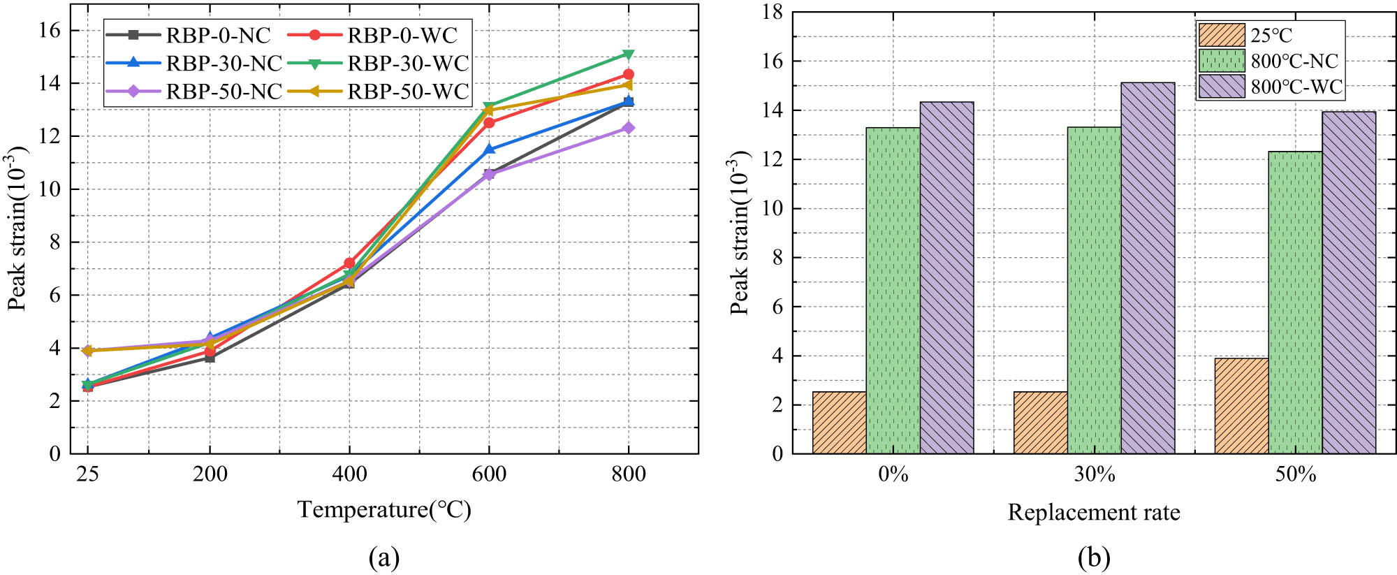
Peak strain of RBP-UHPC after high temperature: (a) the change of peak strain with temperature and (b) the change of peak strain with RBP replacement rate.
3.4 Elastic modulus
The elastic modulus is an important parameter for the elastic deformation resistance of RBP-UHPC after high temperatures. Figure 8 is a histogram of the initial elastic modulus E 0T (secant modulus at 0.5 f cT) and the peak secant modulus E cT (secant modulus at f cT) of UHPC specimens after high temperature.

Elastic modulus of RBP-UHPC after high temperature. (a) Initial elastic modulus: NC (left) and WC (right) and (b) peak secant modulus: NC (left) and WC (right).
The initial elastic modulus of RBP-UHPC is consistent with the peak secant modulus, which decreases with the increase in temperature. At 25–200°C, the initial elastic modulus under NC decreased slightly, and the specimens RBP-0-NC, RBP-30-NC, and RBP-50-NC decreased by 24.0, 21.2, and 24.5%, respectively, while the WC specimens decreased by 25.5, 28.1, and 27.8%, respectively. Under the same conditions, the initial elastic and peak secant modulus decreased with increased RBP replacement rates. The initial elastic modulus of RBP-30-WC and RBP-50-WC at 400°C is 34.1 and 33.7% at room temperature, and the peak secant modulus is 34.1 and 35.4% at room temperature. The initial elastic modulus of RBP-30-NC at 800°C is the most reduced among all NC specimens, with a reduction of 90.5%.
Similarly, the initial elastic modulus of RBP-30-WC is the most reduced in WC specimens, with a decrease of 93.4%; the incorporation of RBP has little effect on the elastic modulus after high temperature. The high elastic modulus of UHPC can be attributed to the presence of steel fibers in its matrix [50]. The bridging of steel fibers enhances the toughness of the matrix and plays a role in crack resistance. When the temperature increases, the hydration products decompose and shrink, the steel fiber expands by heat, and the WC accelerates the expansion and corrosion of the steel fiber. The connection between the cement matrix and the steel fiber is no longer close, and the bridging effect of the steel fiber is gradually weakened. Therefore, the initial elastic modulus and peak secant modulus of UHPC decrease.
3.5 Poisson’s ratio
Poisson’s ratio corresponding to the 50% peak stress in the rising section of the uniaxial compressive stress–strain curve is taken. Figure 9 shows the change of Poisson’s ratio of RBP-UHPC with temperature under different cooling methods after high temperature.

Poisson’s ratio of RBP-UHPC after high temperature: (a) NC and (b) WC.
It can be seen from Figure 9 that with the increase in temperature, Poisson’s ratio of each group of specimens decreases first and then increases. Under NC, Poisson’s ratio of each group of specimens reached the minimum value at 600℃. RBP-0 had the smallest value, RBP-50 was the second smallest, and RBP-30 had the largest value. Compared with room temperature, these three values decreased by 20.1, 20.4, and 14.7%, respectively. With the further increase in temperature, at 800°C, Poisson’s ratio of RBP-30 was the largest, and Poisson’s ratio of RBP-50 was the smallest. Compared with room temperature, they decreased by 11.3 and 16%, respectively, but Poisson’s ratio of the three groups of specimens was smaller than that at room temperature. The specimens under WC reached the minimum value at 400°C, among which RBP-50 was the smallest, RBP-0 was the second, and RBP-30 was the largest. The three groups of specimens decreased by 21.8, 17.3, and 12.5%, respectively, compared with room temperature. When the temperature reached 800°C, Poisson’s ratio of RBP-30 was the largest, and Poisson’s ratio of RBP-50 was the smallest. The two groups of specimens decreased by 3.5 and 9.7%, respectively, compared with room temperature. Similar to NC, Poisson’s ratio under WC was smaller than that at room temperature. In addition, Poisson’s ratio of the specimens under WC after 600°C high temperature is greater than that under NC, and the incorporation of RBP has a certain beneficial effect on Poisson’s ratio of the specimens under the two cooling methods after high temperature. When the heating temperature is less than 200°C, Poisson’s ratio of the RBP-50 group is the highest among all the specimens. When the heating temperature is greater than 400°C, Poisson’s ratio of the RBP-30 group is the highest among all the specimens. By analyzing the above phenomenon, it may be that with the increase in temperature, the unhydrated cement continues to consume water to hydrate in the autoclaved environment of the blast furnace, the matrix is denser, and the deformation is small. When the temperature continues to rise, on the one hand, the hydration products begin to decompose; on the other hand, the steel fiber gradually oxidizes and expands, losing its lateral restraint ability, so that the Poisson’s ratio of the specimen increases after high temperature. The incorporation of RBP can not only generate C–S–H gel to a certain extent but also partially fill the pores after decomposition. Therefore, an appropriate amount of incorporation can reduce the Poisson’s ratio to a certain extent, while WC further aggravates the damage of the matrix, so that the Poisson’s ratio after 600°C is greater than that under NC.
4 Constitutive relationship of RBP-UHPC under uniaxial compression after high temperature
The compressive stress–strain relationship of RBP-UHPC after high temperature is the basis for the damage assessment of RBP-UHPC structure after the fire incident. In this section, we develop a uniaxial compressive stress–strain constitutive model suitable for RBP-UHPC after high temperatures based on the geometric characteristics and mathematical modeling of the uniaxial compressive stress–strain curve of RBP-UHPC after elevated temperatures.
4.1 Geometric characteristics and equation of compressive stress–strain full curve
The constitutive models of cement-based materials can be divided into two categories: (1) constitutive models based on mechanical theory and (2) empirical models based on experiments. The typical full stress–strain curve of concrete under uniaxial compression is shown in Figure 10. The coordinates in the diagram are dimensionless. The shape, characteristics, and seven geometric conditions of the full compression curve can effectively reflect the characteristics of the whole process of compression of the specimen after compression, such as deformation, crack development, damage accumulation, and failure of concrete [51].

Typical compressive stress–strain curve of concrete.
The RBP-UHPC uniaxial compression stress–strain curve is normalized to obtain the standard curve, as shown in Figure 11. It is not difficult to find that the stress–strain curve of RBP-UHPC after high temperature has similar geometric characteristics with the typical compressive stress–strain curve of ordinary concrete so that the UHPC model can refer to the ordinary concrete model. In addition, at different target temperatures, the curves of RBP-UHPC under the two cooling methods are close, so the same model can be used to express.

Normalized stress–strain curve of UHPC after high temperature: (a) NC and (b) WC.
For the ordinary concrete equation, many scholars have proposed a variety of mathematical function forms such as trigonometric function, exponential function, rational fraction, polynomial, and so on, commonly used models such as Young, CEB-FIP, Hognestad, and Guo Zhenhai [52–54]. After comparative analysis, this article intends to adopt a segmented model, in which the rising section adopts a polynomial, and the falling section adopts a rational and continuous curve equation at the peak point as the UHPC uniaxial compression constitutive model after high temperature [51,54,55].
1) Ascending curve
Due to the high strength of UHPC, the elastic part of the rising section measured by the experiment is longer, which can be fitted by a 5-degree polynomial, such as Equation (4).
Substituting the geometric condition (1) of a typical compression curve, we obtain
So
Substituting the geometric conditions (3) of the typical compression curve into Equation (5),
Simultaneous solution:
Substituting Equation (7) into Equation (5), we obtain
There is only a single parameter a left, and when x = 0,
It can be seen that a is the ratio of the initial elastic modulus to the peak secant modulus.
At this time, Equation (9) is substituted into the geometric conditions (1) and (3) of the typical compression curve, and the conditions (7) are satisfied at the same time.
According to the geometric condition (2), when 0 ≤ x < 1,
So,
Get
Because of Equation (9) and E
0T ≥ E
cT > 0, so a ≥ 1, that is, the value range of a is
Therefore, the equation of the rising section is
2) Descending curve
As shown in Figure 11, the descending section of RBP-UHPC after high temperature has a large discreteness but roughly conforms to the rational fractional form of Equation (13):
According to the geometric condition (4), b 3 = b, b 2 = 1 − 2b are obtained. Substituting into Equation (13), we obtain
According to the geometric condition (7), for x ≥ 1, 0 ≤ y ≤ 1, that is
Get b ≥ 0. When b = 0, y ≡ 1, the descending section is a horizontal line; that is, concrete is an ideal plastic material; when b → +∞, y ≡ 0, concrete is completely brittle. These two cases are not consistent, so 0 < b < +∞.
The first-order, second-order, and third-order derivatives of Equation (14) are as follows:
According to geometric condition (4), we obtain
Let
According to geometric condition (5), we obtain
Let
Because b > 0, x
B > 1, so when 1 ≤ x < x
B,
Therefore, the equation of the descending section is
In summary, Equations (12) and (23) meet all the geometric conditions of Equations (1)–(7). Therefore, the stress–strain curve equation of RBP-UHPC after high temperature is
In the equation,
4.2 Discussion of equation parameters
The parameter a in Equation (24) reflects the change of elastic modulus. The larger the value of a, the smaller the proportion of the elastic stage in the ascending phase of the stress–strain curve, and its value can be calculated by the ratio of the initial elastic modulus to the peak secant modulus (E 0T/E cT) (Table 7). Figure 12 is the comparison between the experimental curve and the theoretical curve of the ascent section. It is not difficult to find that the experimental curve of the ascent section generally falls within the theoretical curve range of a = 0.79 and a = 1.4, and the larger the a value, the steeper the slope of the ascent section.
Ratio of initial elastic modulus to peak elastic modulus
| Temperature (℃) | Ratio of initial elastic modulus to peak elastic modulus | |||||
|---|---|---|---|---|---|---|
| RBP-0 | RBP-30 | RBP-50 | ||||
| NC | WC | NC | WC | NC | WC | |
| 25 | 1.26 | 1.21 | 1.19 | |||
| 200 | 1.15 | 1.25 | 1.34 | 1.24 | 1.26 | 1.20 |
| 400 | 1.12 | 1.18 | 1.18 | 1.21 | 1.32 | 1.11 |
| 600 | 1.16 | 1.26 | 1.34 | 1.32 | 1.16 | 1.20 |
| 800 | 1.05 | 0.92 | 0.98 | 0.79 | 0.89 | 0.88 |

Comparison between the experimental curve and the theoretical curve of the ascent stage: (a) NC and (b) WC.
According to the model of Zhenhai [55], the parameter b is related to the area of the descending section of the curve. The larger the value is, the steeper the descending section of the curve is. Different from the rising section, the descending section is more discrete. The value of parameter b can be obtained by fitting the measured curve data. The specific value is shown in Table 8. The parameter b decreases with the increase of temperature, and the WC value is greater than the NC. Bringing parameters a and b into Equation (24), the comparison of the theoretical curve and the test curve is shown in Figures 13 and 14, and the two are in good condition.
Parameter values of RBP-UHPC descending section after high temperature
| Cooling method | 600℃ | 800℃ |
|---|---|---|
| NC | 20.28 | 10.36 |
| WC | 27.14 | 15.21 |

Stress–strain curve fitting of RBP-UHPC after high temperature under NC: (a) 25°C, (b) 200°C, (c) 400°C, (d) 600°C, and (e) 800°C.

Stress–strain curve fitting of RBP-UHPC after high temperature under WC: (a) 200°C, (b) 400°C, (c) 600°C, and (d) 800°C.
5 Conclusion
This study analyzes the effect of the RBP replacement rate, particularly at high temperature, on properties of RBP-UHPC, such as stress–strain behavior, Poisson’s ratio, elastic modulus, and axial compressive strength via uniaxial compression tests. Regression analysis establishes an equation to predict the axial compressive strength of RBP-UHPC considering temperature, RBP replacement rate, and cooling method. Additionally, a constitutive equation for axial compression in RBP-UHPC after high-temperature exposure is proposed based on experimental findings. The following are key results:
The axial compression stress–strain curve of RBP-UHPC shows similarities in shape between temperatures below 400 and 25°C. However, as the temperature escalates from 600 to 800°C, the curve gradually flattens, with the peak point shifting to the lower right. Comparatively, WC yields a flatter curve with a peak at the lower right. Under NC, axial compressive strength initially increases, peaking at 200°C before declining. With WC, except for RBP-30, strength decreases with temperature increase. Considering the whole heating process, when the RBP content is 30%, the axial compression strength is the best.
As the target temperature increases, peak strain rises most significantly at 600°C. The initial elastic and peak secant modulus decrease continuously, notably at 400°C. At 800°C, the UHPC with a 30% RBP replacement rate shows the highest initial elastic modulus, while the UHPC with a 50% RBP substitution rate has the highest peak secant modulus. WC generally results in larger peak strain and smaller initial elastic and peak secant modulus compared to NC. Poisson’s ratio in RBP-UHPC decreases then increases after high temperature exposure, while at room temperature, it rises with increasing RBP replacement. After 600°C, WC yields a greater Poisson’s ratio than NC.
The formula for calculating the axial compressive strength of RBP-UHPC, considering the influence of simulated fire temperature, is proposed. Additionally, a uniaxial compression constitutive model for RBP-UHPC is established, accounting for the effects of simulated fire temperature and cooling conditions. A uniaxial compression constitutive model for RBP-UHPC is developed, considering geometric characteristics and the impact of simulated fire temperature and cooling conditions. This model is a valuable reference for assessing the load-bearing capacity and repairing RBP-UHPC structures after exposure to high temperatures.
5.1 Future recommendations
In order to better understand the elevated temperature effects on the mechanical and flexural behavior of RBP-UHPC, future work was recommended as follows:
Validating the proposed constitutive model through finite-element analysis or large-scale fire resistance tests.
Additional studies are needed to consider the effects of RBP types and content on the high-temperature performance of UHPC.
Investigate the combined influence of high temperature and sustained loads on the mechanical behavior of RBP-UHPC.
Investigate the combined effects of RBP type and replacement rate on high-temperature behavior.
Explore the impact of fiber reinforcement on the mechanical properties of RBP-UHPC exposed to fire.
Funding information
This study was funded by the Natural Foundation of China (grant number 52178258) and the Henan Provincial Department of Transportation Science and Technology plan project (2021J3).
-
Author contributions: All authors have accepted responsibility for the entire content of this manuscript and consented to its submission to the journal, reviewed all the results and approved the final version of the manuscript. YC: conceptualization, methodology, supervision, resources, writing – review and editing. ZJ: methodology, formal analysis, investigation, writing – original draft preparation. AR: formal analysis, writing – review and editing. FW: visualization, writing – review and editing.
-
Conflict of interest: Authors state no conflict of interest.
-
Data availability statement: Authors declare that the data employed and analyzed during the current study will be available from the corresponding author upon request, and we are committed to providing access to our data to ensure the transparency and reproducibility of our findings.
References
[1] De Larrard F, Sedran T. Optimization of ultra-high-performance concrete by the use of a packing model. Cem Concr Res. 1994;24(6):997–1009. 10.1016/0008-8846(94)90022-1.Suche in Google Scholar
[2] Rosseli SR, Sidek MNM, Saman HM, Arshad MF, Jaafar MFM, Ridzuan ARM, et al. Ultra High-performance concrete as alternative repair method: a review. J Fail Anal Prev. 2021;21:2072–80. 10.1007/s11668-021-01296-3.Suche in Google Scholar
[3] Akhnoukh AK, Buckhalter C. Ultra-high-performance concrete: Constituents, mechanical properties, applications and current challenges. Case Stud Constr Mater. 2021;15:e00559. 10.1016/j.cscm.2021.e00559.Suche in Google Scholar
[4] Abbas S, Nehdi M, Saleem M. Ultra-high performance concrete: Mechanical performance, durability, sustainability and implementation challenges. Int J Concr Struct Mater. 2016;10:271–95. 10.1007/s40069-016-0157-4.Suche in Google Scholar
[5] Gu C, Ye G, Sun W. Ultrahigh performance concrete-properties, applications and perspectives. Sci China Technol Sci. 2015;58:587–99. 10.1007/s11431-015-5769-4.Suche in Google Scholar
[6] Brühwiler E. UHPFRC technology to enhance the performance of existing concrete bridges. Struct Infrastruct Eng. 2020;16(1):94–105. 10.1080/15732479.2019.1605395.Suche in Google Scholar
[7] Bažant ZP, Zhou Y. Why did the world trade center collapse? —Simple analysis. Journal of Engineering Mechanics. 2002;128(1):2-6. 10.1061/(ASCE)0733-9399(2002)128:1(2).Suche in Google Scholar
[8] Luo D, Lu T, Chen YF. Application of ultra-high-performance concrete in prefabricated buildings. Mater Test. 2021;63(12):1174–83. 10.1515/mt-2021-0043.Suche in Google Scholar
[9] Abid M, Hou X, Zheng W, Hussain RR. High temperature and residual properties of reactive powder concrete–A review. Constr Build Mater. 2017;147:339–51. 10.1016/j.conbuildmat.2017.04.083.Suche in Google Scholar
[10] Korpa A, Kowald T, Trettin R. Phase development in normal and ultra high performance cementitious systems by quantitative X-ray analysis and thermoanalytical methods. Cem Concr Res. 2009;39(2):69–76. 10.1016/j.cemconres.2008.11.003.Suche in Google Scholar
[11] USGS (U.S. Geological Survey), 2021. Mineral Commodity 1086 Summaries 2021. USGS Available.Suche in Google Scholar
[12] ECA (European Cement Association), 2020a. Global Cement 929 Production. ECA Available.Suche in Google Scholar
[13] Rashad AM. An exploratory study on high-volume fly ash concrete incorporating silica fume subjected to thermal loads. J Clean Prod. 2015;87:735–44. 10.1016/j.jclepro.2014.09.018.Suche in Google Scholar
[14] Bosoaga A, Masek O, Oakey JE. CO2 capture technologies for cement industry. Energy procedia. 2009;1(1):133–40. 10.1016/j.egypro.2009.01.020.Suche in Google Scholar
[15] He Z, Shen M, Shi J, Yalçınkaya Ç, Du S, Yuan Q. Recycling coral waste into eco-friendly UHPC: Mechanical strength, microstructure, and environmental benefits. Sci Total Environ. 2022;836:155424. 10.1016/j.scitotenv.2022.155424.Suche in Google Scholar PubMed
[16] Ahmad S, Mohaisen KO, Adekunle SK, Al-Dulaijan SU, Maslehuddin M. Influence of admixing natural pozzolan as partial replacement of cement and microsilica in UHPC mixtures. Constr Build Mater. 2019;198:437–44. 10.1016/j.conbuildmat.2018.11.260.Suche in Google Scholar
[17] Tang Q, Ma Z, Wu H, Wang W. The utilization of eco-friendly recycled powder from concrete and brick waste in new concrete: A critical review. Cem Concr Compos. 2020;114:103807. 10.1016/j.cemconcomp.2020.103807.Suche in Google Scholar
[18] Wild S, Gailius A, Hansen H, Pederson L, Szwabowski J. Pozzolanic properties of a variety of European clay bricks. Build Res & Inf. 1997;25(3):170–5. 10.1080/096132197370435.Suche in Google Scholar
[19] Olofinnade OM, Ede AN, Ndambuki JM, Bamigboye G. Structural properties of concrete containing ground waste clay brick powder as partial substitute for cement. Materials Science Forum, Trans Tech Publ.; 2016. 10.4028/www.scientific.net/MSF.866.63.Suche in Google Scholar
[20] Yuan C, Fu W, Raza A, Li H. Study on mechanical properties and mechanism of recycled brick powder UHPC. Buildings. 2022;12(10):1622. 10.3390/buildings12101622.Suche in Google Scholar
[21] Zhang Y, Raza A, Umar M, Chen Y, Yuan C. Study on frost resistance and interface bonding performance through the integration of recycled brick powder in ultra-high-performance concrete for structural reinforcement. Materials. 2023;16(21):6999. 10.3390/ma16216999.Suche in Google Scholar PubMed PubMed Central
[22] Memon B, Oad M, Buller A, Raza A. Effect of curing methods on tensile strength of green concrete cylinders made with demolishing coarse aggregates. World J Eng Res Technol. 2020;6(2):66–75. 10.13140/RG.2.2.13008.87045.Suche in Google Scholar
[23] Zhu Y, Hussein H, Kumar A, Chen G. A review: Material and structural properties of UHPC at elevated temperatures or fire conditions. Cem Concr Compos. 2021;123:104212. 10.1016/j.cemconcomp.2021.104212.Suche in Google Scholar
[24] Du Y, Qi H-H, Huang S-S, Liew JR. Experimental study on the spalling behaviour of ultra-high strength concrete in fire. Constr Build Mater. 2020;258:120334. 10.1016/j.conbuildmat.2020.120334.Suche in Google Scholar
[25] Banerji S, Kodur V, Solhmirzaei R. Experimental behavior of ultra high performance fiber reinforced concrete beams under fire conditions. Eng Struct. 2020;208:110316. 10.1016/j.engstruct.2020.110316.Suche in Google Scholar
[26] Ye H, Feng N, Ling-hu Y, Ran Z, Lin L, Qi S, et al. Research on fire resistance of ultra-high-performance concrete. Adv Mater Sci Eng. 2012;2012. 10.1155/2012/530948.Suche in Google Scholar
[27] Schneider U, Diederichs U. Verhalten von ultrahochfesten Betonen (UHPC) unter Brandbeanspruchung. Beton‐und Stahlbetonbau. 2003;98(7):408–17. 10.1002/best.200301900.Suche in Google Scholar
[28] Maier M, Zeiml M, Lackner R. On the effect of pore-space properties and water saturation on explosive spalling of fire-loaded concrete. Constr Build Mater. 2020;231:117150. 10.1016/j.conbuildmat.2019.117150.Suche in Google Scholar
[29] Li M, Qian C, Sun W. Mechanical properties of high-strength concrete after fire. Cem Concr Res. 2004;34(6):1001–5. 10.1016/j.cemconres.2003.11.007.Suche in Google Scholar
[30] Savva A, Manita P, Sideris K. Influence of elevated temperatures on the mechanical properties of blended cement concretes prepared with limestone and siliceous aggregates. Cem Concr Compos. 2005;27(2):239–48. 10.1016/j.cemconcomp.2004.02.013.Suche in Google Scholar
[31] Tang J, Ma W, Pang Y, Fan J, Liu D, Zhao L, et al. Uniaxial compression performance and stress–strain constitutive model of the aluminate cement-based UHPC after high temperature. Constr Build Mater. 2021;309:125173. 10.1016/j.conbuildmat.2021.125173.Suche in Google Scholar
[32] Wu Z, Shi C, He W, Wu L. Effects of steel fiber content and shape on mechanical properties of ultra high performance concrete. Constr Build Mater. 2016;103:8–14. 10.1016/j.conbuildmat.2015.11.028.Suche in Google Scholar
[33] Shah I, Li J, Khan N, et al. Bond-slip behavior of steel bar and recycled steel fibre-reinforced concrete. J Renew Mater. 2024;12(1). 10.32604/jrm.2023.031503.Suche in Google Scholar
[34] Xiong MX, Liew JYR. Spalling behavior and residual resistance of fibre reinforced Ultra-High performance concrete after exposure to high temperatures. Mater Constr. 2015;65(320).10.3989/mc.2015.00715Suche in Google Scholar
[35] Tayeh B, Hadzima-Nyarko M, Riad MYR, Hafez RDA. Behavior of ultra-high-performance concrete with hybrid synthetic fiber waste exposed to elevated temperatures. Buildings. 2023;13(1):129. 10.3390/buildings13010129.Suche in Google Scholar
[36] Sciarretta F, Fava S, Francini M, Ponticelli L, Caciolai M, Briseghella B, et al. Ultra-High performance concrete (UHPC) with polypropylene (Pp) and steel Fibres: Investigation on the high temperature behaviour. Constr Build Mater. 2021;304:124608. 10.1016/j.conbuildmat.2021.124608.Suche in Google Scholar
[37] Chen H-J, Yu Y-L, Tang C-W. Mechanical properties of ultra-high performance concrete before and after exposure to high temperatures. Materials. 2020;13(3):770. 10.3390/ma13030770.Suche in Google Scholar PubMed PubMed Central
[38] Yu Z, Yang Q, Zhang J, Peng S. Research on uniaxial mechanical performance of high-performance concrete after high temperature rapid cooling and damage mechanism analysis. J Build Eng. 2024;108921. 10.1016/j.jobe.2024.108921.Suche in Google Scholar
[39] Dimitri R, Rinaldi M, Tornabene F, Micelli F. Numerical study of the FRP-concrete bond behavior under thermal variations. Curved Layer Struct. 2023;10(1):20220193. 10.1515/cls-2022-0193.Suche in Google Scholar
[40] Yang J, Peng G-F, Zhao J, Shui G-S. On the explosive spalling behavior of ultra-high performance concrete with and without coarse aggregate exposed to high temperature. Constr Build Mater. 2019;226:932–44. 10.1016/j.conbuildmat.2019.07.299.Suche in Google Scholar
[41] Raza A, Memon BA, Oad M. Effect of curing types on compressive strength of recycled aggregates concrete. QUEST Res J. 2019;17(2):7–12. 10.13140/RG.2.2.35161.95844.Suche in Google Scholar
[42] Yuan C, Xu S, Raza A, Wang C, Wang D. Influence and mechanism of curing methods on mechanical properties of manufactured sand UHPC. Materials. 2022;15(18):6183. 10.3390/ma15186183.Suche in Google Scholar PubMed PubMed Central
[43] Shi C, Mo Y-L. High-performance construction materials: science and applications. World scientific; 2008.10.1142/9789812797360Suche in Google Scholar
[44] Yuan C, Wang D, Setiawan H, Wei Y. Effect and mechanism of different excitation modes on the activities of the recycled brick micropowder. Sci Eng Compos Mater. 2021;28(1):676–88. 10.1515/secm-2021-0062.Suche in Google Scholar
[45] China Engineering Construction Standardization Association. T/CECS 10107-2020 Technical Requirements for Ultra-High-Performance Concrete [ S]. Beijing: China Standards Press; 2020 (in Chinese).Suche in Google Scholar
[46] Y Wei. Experimental study on mix proportion design and basic mechanical properties of recycled micro-powder UHPC [D]. [Master’s degree thesis]. Henan: Zhengzhou University; 2021 (in Chinese). 10.27466/d.cnki.gzzdu.2021.002998.Suche in Google Scholar
[47] Zhenwei L. Research on mechanical properties and microstructure of limestone manufactured sand concrete after high temperature. [ Master ‘s thesis]. Guangxi: Guangxi University; 2021 (in Chinese). 10.27034/d.cnki.ggxiu.2021.000441.Suche in Google Scholar
[48] Dougill J. Some effects of thermal volume changes on the properties and behaviour of concrete; 1968.Suche in Google Scholar
[49] Huang L, Du Y, Zhu S, Wang L. Material property and constitutive model of C120 hybrid fiber ultra-high performance concrete at elevated temperatures. Structures. Elsevier; 2023. 10.1016/j.istruc.2023.02.057.Suche in Google Scholar
[50] Alsalman A, Dang CN, Prinz GS, Hale WM. Evaluation of modulus of elasticity of ultra-high performance concrete. Constr Build Mater. 2017;153:918–28. 10.1016/j.conbuildmat.2017.07.158 Suche in Google Scholar
[51] Haiyan L. Research on high temperature burst and mechanical properties of reactive powder concrete after high temperature [D]. [ Doctoral Dissertation]. Heilongjiang: Harbin Institute of Technology; 2012 (in Chinese).Suche in Google Scholar
[52] Rusch H. Stress- strain relationships for concrete. J ACI. 1960;34(5):268–80.Suche in Google Scholar
[53] Hognestad E, Hanson NW, McHenry D. Concrete stress distribution in ultimate strength design. Journal Proceedings; 1955. 10.14359/11609.Suche in Google Scholar
[54] Zhenhai G. Strength and deformation of concrete – experimental basis and constitutive relationship. Beijing, China: Tsinghua University Press; 1997 (in Chinese).Suche in Google Scholar
[55] Zhenhai G. Strength and constitutive relationship of concrete: principle and application. Beijing, China: China Building Industry Press; 2004.Suche in Google Scholar
© 2024 the author(s), published by De Gruyter
This work is licensed under the Creative Commons Attribution 4.0 International License.
Artikel in diesem Heft
- Regular Articles
- Research on damage evolution mechanisms under compressive and tensile tests of plain weave SiCf/SiC composites using in situ X-ray CT
- Structural optimization of trays in bolt support systems
- Continuum percolation of the realistic nonuniform ITZs in 3D polyphase concrete systems involving the aggregate shape and size differentiation
- Multiscale water diffusivity prediction of plain woven composites considering void defects
- The application of epoxy resin polymers by laser induction technologies
- Analysis of water absorption on the efficiency of bonded composite repair of aluminum alloy panels
- Experimental research on bonding mechanical performance of the interface between cementitious layers
- A study on the effect of microspheres on the freeze–thaw resistance of EPS concrete
- Influence of Ti2SnC content on arc erosion resistance in Ag–Ti2SnC composites
- Cement-based composites with ZIF-8@TiO2-coated activated carbon fiber for efficient removal of formaldehyde
- Microstructure and chloride transport of aeolian sand concrete under long-term natural immersion
- Simulation study on basic road performance and modification mechanism of red mud modified asphalt mixture
- Extraction and characterization of nano-silica particles to enhance mechanical properties of general-purpose unsaturated polyester resin
- Roles of corn starch and gellan gum in changing of unconfined compressive strength of Shanghai alluvial clay
- A review on innovative approaches to expansive soil stabilization: Focussing on EPS beads, sand, and jute
- Experimental investigation of the performances of thick CFRP, GFRP, and KFRP composite plates under ballistic impact
- Preparation and characterization of titanium gypsum artificial aggregate
- Characteristics of bulletproof plate made from silkworm cocoon waste: Hybrid silkworm cocoon waste-reinforced epoxy/UHMWPE composite
- Experimental research on influence of curing environment on mechanical properties of coal gangue cementation
- Multi-objective optimization of machining variables for wire-EDM of LM6/fly ash composite materials using grey relational analysis
- Synthesis and characterization of Ag@Ni co-axial nanocables and their fluorescent and catalytic properties
- Beneficial effect of 4% Ta addition on the corrosion mitigation of Ti–12% Zr alloy after different immersion times in 3.5% NaCl solutions
- Study on electrical conductive mechanism of mayenite derivative C12A7:C
- Fast prediction of concrete equivalent modulus based on the random aggregate model and image quadtree SBFEM
- Research on uniaxial compression performance and constitutive relationship of RBP-UHPC after high temperature
- Experimental analysis of frost resistance and failure models in engineered cementitious composites with the integration of Yellow River sand
- Influence of tin additions on the corrosion passivation of TiZrTa alloy in sodium chloride solutions
- Microstructure and finite element analysis of Mo2C-diamond/Cu composites by spark plasma sintering
- Low-velocity impact response optimization of the foam-cored sandwich panels with CFRP skins for electric aircraft fuselage skin application
- Research on the carbonation resistance and improvement technology of fully recycled aggregate concrete
- Study on the basic properties of iron tailings powder-desulfurization ash mine filling cementitious material
- Preparation and mechanical properties of the 2.5D carbon glass hybrid woven composite materials
- Improvement on interfacial properties of CuW and CuCr bimetallic materials with high-entropy alloy interlayers via infiltration method
- Investigation properties of ultra-high performance concrete incorporating pond ash
- Effects of binder paste-to-aggregate ratio and polypropylene fiber content on the performance of high-flowability steel fiber-reinforced concrete for slab/deck overlays
- Interfacial bonding characteristics of multi-walled carbon nanotube/ultralight foamed concrete
- Classification of damping properties of fabric-reinforced flat beam-like specimens by a degree of ondulation implying a mesomechanic kinematic
- Influence of mica paper surface modification on the water resistance of mica paper/organic silicone resin composites
- Impact of cooling methods on the corrosion behavior of AA6063 aluminum alloy in a chloride solution
- Wear mechanism analysis of internal chip removal drill for CFRP drilling
- Investigation on acoustic properties of metal hollow sphere A356 aluminum matrix composites
- Uniaxial compression stress–strain relationship of fully aeolian sand concrete at low temperatures
- Experimental study on the influence of aggregate morphology on concrete interfacial properties
- Intelligent sportswear design: Innovative applications based on conjugated nanomaterials
- Research on the equivalent stretching mechanical properties of Nomex honeycomb core considering the effect of resin coating
- Numerical analysis and experimental research on the vibration performance of concrete vibration table in PC components
- Assessment of mechanical and biological properties of Ti–31Nb–7.7Zr alloy for spinal surgery implant
- Theoretical research on load distribution of composite pre-tightened teeth connections embedded with soft layers
- Coupling design features of material surface treatment for ceramic products based on ResNet
- Optimizing superelastic shape-memory alloy fibers for enhancing the pullout performance in engineered cementitious composites
- Multi-scale finite element simulation of needle-punched quartz fiber reinforced composites
- Thermo-mechanical coupling behavior of needle-punched carbon/carbon composites
- Influence of composite material laying parameters on the load-carrying capacity of type IV hydrogen storage vessel
- Review Articles
- Effect of carbon nanotubes on mechanical properties of aluminum matrix composites: A review
- On in-house developed feedstock filament of polymer and polymeric composites and their recycling process – A comprehensive review
- Research progress on freeze–thaw constitutive model of concrete based on damage mechanics
- A bibliometric and content analysis of research trends in paver blocks: Mapping the scientific landscape
- Bibliometric analysis of stone column research trends: A Web of Science perspective