Experimental studies on the possibility of using a pulsed laser for spot welding of thin metallic foils
-
Piotr Sęk

Abstract
The purpose of the experiment was to study the influence of the laser beam in pulse mode on metallic foils in order to obtain a spot weld. The welding process was carried out using the overlap weld method, using spot welds in various quantities. The Nd - YAG BLS 720 pulsed laser was used to conduct the experiment. The impact of the number of spot welds on the value of force needed to break the sample was examined. A number of measurements were carried out to determine the best process parameters. Butt welding and overlap welding were also performed using a continuous weld consisting of spot welds. Weld strength tests were performed to select the most appropriate parameters for the process under consideration.
1 Introduction
Laser welding is one of the main applications of lasers in the technological treatment of materials. Due to the characteristics of the process: small amount of heat input to the material, universality of the process, precision and ease of automation, laser welding is a technology competitive to the common technologies. It allows to obtain a weld of the highest quality without the need to use additional hot-melt materials. The range of materials that can be joined using the laser method is very broad, covering most metals and their alloys, as well as plastics. Laser welding allows for making various types of joints in any position. The parameters of modern lasers allow for effective and highly efficient joining of large-size elements as well as micromachining of elements with thicknesses in the micro range. Due to its efficiency and precision, laser welding becomes a competitive method both for arc welding in gas shields and pressure welding, as well as for modern methods of electron beam and plasma arc welding. In many cases, it can also be a supplementary method to these welding methods [1, 2, 3].
Due to their many advantages, laser technologies are used for cutting, welding, marking, surface hardening, flood welding, remelting and micromachining. The energy range of a pulsed laser determines its ability to produce a pulse of a specified power, pulse repetition rate and duration. The weld formed as a result of the impact of the laser beam emitted in the impulse mode consists of many over-lapping spot welds. The range of overlapping of individual pulses, determined in percent, shows to what extent the material area melted by a single pulse overlaps with the area created by the preceding pulse. With parameters such as welding speeds and pulse repetition rates, the tightness of the weld, the amount of heat supplied to the weld metal and the actual melt depth can be optimised, and the homogeneity of the weld structure can be affected. Pulse mode lasers are particularly suitable for welding thin-walled elements that are not resistant to large amounts of heat supplied to the joint, causing cracks or deformations [15, 16, 17].
Laser micro-welding is a well-established joining process in the development of microsystems. In particular, the emitted laser energy is absorbed and storedby the workpiece. The portion of energy that heats and melts the material is the actual welding energy. During heating, the energy is dissipated by heat conduction losses. This causes thermal induction and deformation in the welded material. If the thickness of the elements to be joined is small, the relative deformation increases exponentially. The ratio of gap width to material depth has a major impact on the quality of the joint. The larger the gap and the smaller the thickness of the material, the more difficult it is to make a joint [4, 5, 6].
The process of laser micro-welding has found a wider application with the growing trend of miniature components and devices in the electronics, medical, photonics and precision industries. These applications require a fast, precisely controlled and individually adjustable power supply to the welding area [11, 12]. The unique ability of the laser beam to focus on a very small size and produce a fast
but minimal heat transfer makes it the right tool for micro-welding. Laser intensity is scalable in a wide range of ways, both locally and temporally. Laser welding has become the most suitable and preferred method for the automated production of miniature high-value devices compared to conventional resistance welding and brazing [7, 8]. The micro-welding process requires great precision in terms of the selection of treatment parameters and the tooling used. Errors at the stage of planning lead to inconsistencies in the weld obtained. In the case of welding of different types of materials, defects resulting from different physical propertiesmay occur [13, 14]. Laser micro-welding allows to avoid deformations of welded parts, thus maintaining narrow tolerances and minimal interference with the surrounding parts, and is therefore used to join thin metallic foils with a thickness of 0.025 – 0.125 mm and small tubular parts. When microcircuits are joined, the gap distance between the parts to be connected must be less than 5% of their thickness. In some cases, close contact between parts is essential to produce a precise and durable joint. As a rule, the micro-welding process is carried out in an atmosphere of shielding gases, protecting the material from the reaction between the welded material and components of air. The resulting welds are characterized by low volume and high durability [9, 10].
Spot welding is required to fix parts in a certain position before welding the seam. A strong weld is achievable when the welding puddle is deeper than the thickness of the thinner element. The right geometry of the element, precision machining, correct tooling and clamping as well as optimal process parameters are necessary to create a weld that is resistant to cracks, porosity and deformation. The materials often used for laser micro-welding are copper, aluminium, nickel, steel, gold, platinum and titanium alloys [11, 12].
Laser micro-welding is a fast and repeatable process that offers many benefits including:
High quality welding (e.g. smooth seam surface, no oxidation, no deformations),
There is no need for additional fluxing agents,
A minimal heat affected zone, minimising damage to the workpiece,
It is a non-contact process with very good access to hard-to-reach welding areas,
There is no need for a vacuum chamber as required by electron beam welding,
High speed of the process,
This technique can be used to join elements with different geometriesand thicknesses.
The disadvantages of the micro-welding process include the need to prepare the workpieces thoroughly before treatment. The limitations on the thickness of the welded material, excessive deformation, difficulty in achieving close contact between the pairs of elements to be joined.
2 Experiment
The process of micro-welding thin metallic foils was carried out with the use of the Nd – YAG BLS 720 lasers with the following parameters: maximum energy per pulse 400 J, maximum power 150 W, operating frequency 0.1 – 500 Hz, pulse length 0.1 – 20 ms, spot diameter 0.6 mm, wave-length 1064 nm. The materials used in the experiment were 0H18N9 steel foils with a nominal thickness of 50 μm and Ni 99.9% nickel foil with a nominal thickness of 100 μm. A series of measurements were taken to verify the actual thickness of the foil and the deviation of the actual thickness from the nominal thickness was found to be within 1 μm. The biggest problem was the positioning of the elements in relation to each other due to their small thickness. Special tooling was used for this purpose. Spot welds have been made in various quantities at a distance of 1mm. The micro-welding process was carried out in the atmosphere of a protective gas – argon. A schematic diagram of the experiment is shown in Figure 1 and Figure 2 shows the geometric profile of the test weld face.
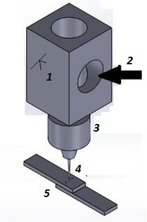
Diagram of the test station, where: 1 – laser head, 2 – laser beam, 3 – focusing lens set, 4 – focused laser radiation, 5 – welded material.

The geometric profile of the test weld face constituting an image of the Nd – YAG BLS 720 laser beam: stereoscopic view on the left, x200 magnification on the right.
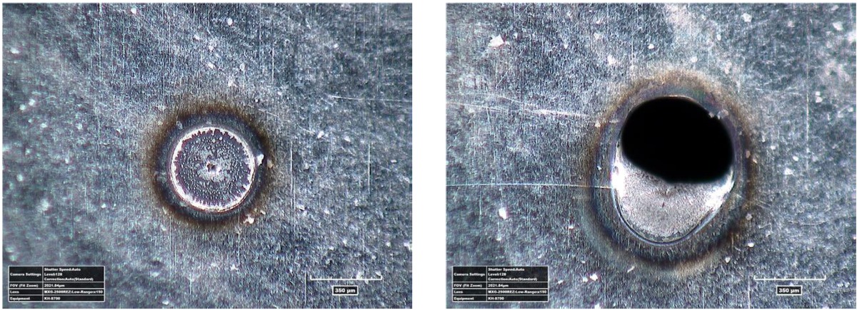
Selection of welding parameters for 0H18N9 steel foil. View of the weld face for the following pulse lengths: left 1ms, right 2ms.
Visual analysis of spot welds made at different pulse lengths was performed using the Hirox KH-8700 optical microscope. During the initial attempts to weld the foil, the laser parameters were selected in such a way as to obtain full weld penetration of the upper and lower elements in the overlap joint of the welded foils. The oscillated parameter was the pulse duration. On the basis of visual tests, optimal parameters of the micro-welding process have been determined for specific materials.
During the initial attempts to weld the foil, the laser parameters were selected in such a way as to obtain full weld penetration of the upper and lower elements in the overlap joint of the welded foils. The oscillated parameter was the pulse duration for the constant energy of 90J in the pulse. On the basis of visual tests, optimal parameters of the micro-welding process have been determined for specific materials. In the case of the 0H18N9 steel foil, the best quality of the spot weld was obtained with a pulse duration of 1ms (Figure 4). In the case of a shorter pulse duration, the exact weld penetration of the lower element in the joint was not obtained. For a pulse duration of 1.5 ms, the upper element was burnt out. Further increase of this parameter resulted in complete burnout of the welded foils. For the nickel foil the optimum pulse duration was equal (Figure 4). With a shorter pulse duration, an accurate and good quality weld was not achieved. Increase in the pulse duration caused an increase in the heat affected zone around the weld obtained. When selecting optimal parameters for joining nickel foil with 0H18N9 steel foil, the biggest problem was to obtain a good quality joint penetration of both elements due to different thickness of the materials being joined. The best quality of the spot weld was obtained at the duration of the pulse equal to 4ms (Figure 5). Increasing this parameter resulted in complete burnout of the welded foils.

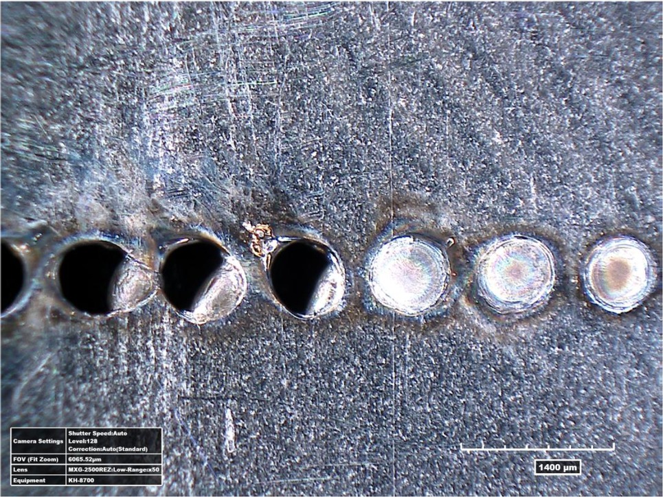
Selection of welding parameters for nickel foil. View of the weld root for the following pulse lengths (from left to right): 8ms, 7ms, 6ms and 5ms.
Selection of welding parameters for joining nickel foil and 0H18N9 steel foil. Face view for the following pulse lengths (from left to right): 7ms, 6 ms, 5ms, 4ms, 3ms and 2ms.
After determining the correct welding parameters for each material, the foil joints were made using different amounts of spot welds to test the strength of the joints. The welds were made at a distance of 1mm. The weld strength test was performed on an Instron 4502 universal testing machine. The strength test specimens were cut using the Trumpf TruMICRO 5325c laser in cold ablation technology to eliminate heat impact on the material while maintaining defined, repeatable dimensions – when the sample was overlapped, a tensile test sample of standard dimensions was obtained. The tensile test process was carried out at a very low velocity of 0.1 mm/s due to the small thicknesses of the materials tested. Two, three and four-spot welds were considered.
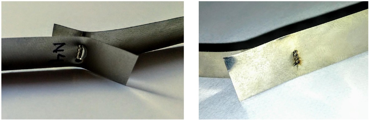
Samples with a four-spot weld broken on the testing machine: Ni/Ni joint on the left, 0H18N9/Ni joint on the right.
Summary of the forces needed to break the prepared samples.
| Force required to break the sample [N] | |||
|---|---|---|---|
| Type of weld | 0H18N9/0H18N9 | Ni/Ni | 0H18N9/Ni |
| two-spot | 37.8 | 128 | 122 |
| three-spot | 43.2 | 177 | 137 |
| four-spot | 47 | 226 | 156.1 |
For the overlap joint of 0H18N9 steel foil, the value of the breaking force increases slightly with an increase in the number of spot welds, but in each case the breakage occurred in the area of the base material and the weld remained intact. In the case of nickel foils, the breakage occurred in the weld area. In the case of a dissimilar joint, the value of the breaking strength is much higher than for steel itself and slightly lower than for a clean nickel foil joint. With the increase in the number of spot welds, the breaking force in this case increased by about 15 N. In the case of the 0H18N9/Ni joint, the rupture occurred in the base material area, and the weld remained intact.
An attempt was made to obtain a continuous weld consisting of spot welds in butt and overlap welding. The butt welding was carried out on 0H18N9 steel foil with a thickness of 50 μm, while the overlap welding was carried out on 0H18N9 steel foil and a dissimilar joint of 0H18N9 steel foil with nickel foil with a thickness of 100 μm, with previously determined optimal process parameters. Due to the significant difference in the thickness of the elements, it was not possible to carry out butt welding of dissimilar materials. The process of butt welding of 0H18N9 steel foil was carried out with a pulse duration of 1ms, a pulse rate of 10 Hz and a welding speed of 200 mm/min. The wide heat affected zone created by welding was apparent here, as a result of which the base material around the weld was deformed. For joining the nickel foil with 0H18N9 steel foil, the pulse duration was increased to 4ms. The resulting weld does not maintain a uniform geometry along the entire length of the joint (Figure 7). The best results were obtained for the overlap joint of 0H18N9 (Figure 7 and 8) steel foil with the same process parameters as for butt welding. The weld retains the same geometry along the entire length of the joint, and the resulting heat affected zone is small and does not affect the geometry of the base material around the weld.
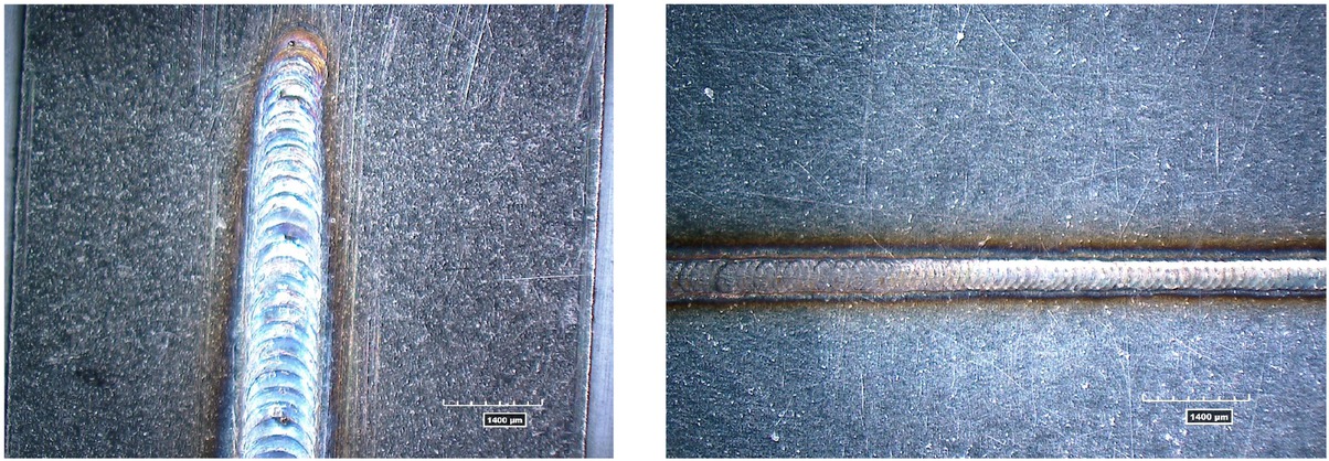
Continuous weld face consisting of spot welds for: on the left – the dissimilar joint 0H18N9/Ni, on the right – 0H18N9/0H18N9.
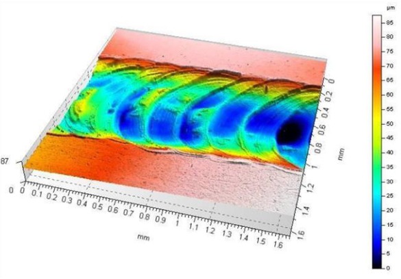
Isometric view of the 0H18N9/0H18N9 weld surface 3D profile tested on the Talysurf CCI Lite optical profiler.
3 Conclusions
The aim of the study was to analyse the possibility of using a pulsed laser for welding thin metallic foils. The tests were carried out using the Nd – YAG BLS 720 laser. The material used in the study was 0H18N9 steel foil with a thickness of 50 μm and Ni 99.9% nickel foil with a thickness of 100 μm. The micro-welding process was carried out using the over-lapweld method.Anumber of test welds have been carried out to determine the optimum process parameters. In the case of the 0H18N9 steel foil, the best quality of the spot weld was obtained with a pulse duration of 1ms. For nickel foil it was 5 ms. For a dissimilar joint, the best quality of a spot weld was obtained with a pulse duration of 4 ms. The foil was then joined using different amounts of spot welds to test the strength of the joints. The spot welds were made at a distance of 1 mm. On the basis of the analysis of the diagrams obtained, the force required to break the sample was determined for different number of welds and individual materials. In case of the overlap joint of 0H18N9 steel foil, the value of the breaking force increases slightly with an increase in the number of spot welds. If the joint is dissimilar, the breaking load increases by approx. 15 N as the number of spot welds increases. The highest strength of the welds was obtained for the overlap joint of the nickel foil. Along with the increase in the number of welds, an increase of about 50 N in the force required to break the sample was noted. An attempt was made to obtain a continuous weld consisting of overlapping spot welds in butt and overlap welding. The butt welding process was carried out on a 50 μm thick 0H18N9 steel foil. The biggest problem was the positioning of the joined elements. Due to the low foil thickness – 50 μm – the heat supplied to the base material during the welding process led to a deformation of the base material around the weld. In the case of the overlap joint of nickel foil and 0H18N9 steel foil, a weld was obtained that does not maintain a uniform geometry along the entire length of the weld. In order to achieve a homogeneousweld, the material had to be cooled down every time the laser beam pulse interacted with the material. The best results were obtained for the overlap joint of 0H18N9 steel foil with the same process parameters as for butt welding. The weld maintains a uniform geometry along the entire length of the weld, and the resulting heat affected zone is small and does not affect the geometry of the base material around the weld.
References
[1] Ul Haque Syed R, Wei J, ji Xu W. Advancement of Laser Micro-Welding, Adv Mat Res 628(2013):183-186. DOI: 10.4028/www.scientific.net/AMR.628.18310.4028/www.scientific.net/AMR.628.183Search in Google Scholar
[2] Ignasiak A, Ambroziak A. Analiza technologii spawania laserowego materiałów trudno spawalnych. Przegląd Spawalnictwa 84. 7-12. https://doi.org/10.26628/wtr.v84i10.32010.26628/ps.v84i10.320Search in Google Scholar
[3] Ventrella VA, Berretta JR, de Rossi W. Application of pulsed Nd:YAG laser in thin foil microwelding. INT J MATER PROD TEC 48(1/2/3/4):194 – 204. DOI: 10.1504/IJMPT.2014.05904210.1504/IJMPT.2014.059042Search in Google Scholar
[4] Radek N, Bartkowiak K.: Laser treatment of electro-spark coatings deposited in the carbon steel substrate with using nanostructured WC-Cu electrodes. Phys. Procedia. 2012, 39, 295-301, https://doi.org/10.1016/j.phpro.2012.10.04110.1016/j.phpro.2012.10.041Search in Google Scholar
[5] Pietraszek J, Radek N, Bartkowiak K. Advanced statistical refinement of surface layer’s discretization in the case of electro-spark deposited carbide-ceramic coatings modified by a laser beam. Solid State Phenom. 197 (2013), 198-202. https://doi.org/10.4028/www.scientific.net/SSP.197.19810.4028/www.scientific.net/SSP.197.198Search in Google Scholar
[6] Radek N, Pietraszek J, Antoszewski B. The average friction coefficient of laser textured surfaces of silicon carbide identified by RSM methodology, Adv Mat Res. 874. 29-34. DOI: 10.4028/www.scientific.net/AMR.874.2910.4028/www.scientific.net/AMR.874.29Search in Google Scholar
[7] Patschger A, Bliedtner J, Bergmann JP. Approaches to increase proces efficiency in laser micro welding, Phys. Procedia 41. 592-602. DOI: 10.1016/j.phpro.2013.03.12110.1016/j.phpro.2013.03.121Search in Google Scholar
[8] Tofil S, Antoszewski K. Badania trwałości złącza NiCr-Pt mikrospawanego laserem Nd:YAG pracującego w silniku spalinowym o zapłonie iskrowym. Inżynieria Maszyn 2011 | R. 16, z. 4 | 52-59 YADDA: bwmeta1.element.baztech-article-LOD6-0031-0032Search in Google Scholar
[9] Yi-Chun L, Ming-Huei Y. Effects of laser beam energy and incydent angle on the pulse laser welding of stainless steel thin sheet, J Mater 190(1):102-108. DOI: 10.1016/j.jmatprotec.2007.03.10210.1016/j.jmatprotec.2007.03.102Search in Google Scholar
[10] Chichkov BN, Momma C, Nolte S, von Alvensleben F, Tünnermann A. Femtosecond, picosecond and nanosecond laser ablation of solid. Appl Phys A-Mater 63, 109-115, DOI: https://doi.org/10.1007/BF01567637https://doi.org/10.1007/BF01567637Search in Google Scholar
[11] Valette S, LeHarzic R, Huot N, Audouard E, Fortunier R. 2D calculations of the thermal effects due to femtosecond laser-metal interaction. Appl. Surf 247. 238-242, DOI: https://doi.org/10.1016/j.apsusc.2005.01.080https://doi.org/10.1016/j.apsusc.2005.01.080Search in Google Scholar
[12] Danielewski H. Laser welding of pipe stubs made from super 304 steel. Numerical simulation and weld properties. Techn Trans. 2019, 1, 167–176, DOI:10.4467/2353737XCT.19.011.1005110.4467/2353737XCT.19.011.10051Search in Google Scholar
[13] Przybyłowicz K, Przybyłowicz J. Materiałoznawstwo w pytaniach i odpowiedziach, WNT Warszawa 2004.Search in Google Scholar
[14] Okamato Y, Glinner A, Olowinsky A, Gedicke J, Uno Y. Fine Micro-welding of Thin Stainless Steel Sheet by High Speed Laser Scanning, JLMN 3(2).95-99 DOI: 10.2961/jlmn.2008.02.000710.2961/jlmn.2008.02.0007Search in Google Scholar
[15] Antoszewski B, Sęk P. Laser surface texturing - chosen problems. Proc. SPIE 8703, Laser Technology 2012: Applications of Lasers, 87030H, https://doi.org/10.1117/12.201524010.1117/12.2015240Search in Google Scholar
[16] Tamaki T,Watanabe W, Itoh K. Laser micro-welding of transparent materials by a localized heat accumulation effect using a femtosecond fiber laser at 1558 nm. Optics Express 14(22).10460-8. DOI: 10.1364/OE.14.01046010.1364/OE.14.010460Search in Google Scholar PubMed
[17] Sakagawa T, Nakashiba S, Hiejima H. Laser Micro Welding System and its Application to Seam Welding of Rechargeable Battery, Phys Procedia12. 6-10. DOI: 10.1016/j.phpro.2011.03.00210.1016/j.phpro.2011.03.002Search in Google Scholar
© 2020 P. Sęk, published by De Gruyter
This work is licensed under the Creative Commons Attribution 4.0 International License.
Articles in the same Issue
- Regular Articles
- Fabrication of aluminium covetic casts under different voltages and amperages of direct current
- Inhibition effect of the synergistic properties of 4-methyl-norvalin and 2-methoxy-4-formylphenol on the electrochemical deterioration of P4 low carbon mold steel
- Logistic regression in modeling and assessment of transport services
- Design and development of ultra-light front and rear axle of experimental vehicle
- Enhancement of cured cement using environmental waste: particleboards incorporating nano slag
- Evaluating ERP System Merging Success In Chemical Companies: System Quality, Information Quality, And Service Quality
- Accuracy of boundary layer treatments at different Reynolds scales
- Evaluation of stabiliser material using a waste additive mixture
- Optimisation of stress distribution in a highly loaded radial-axial gas microturbine using FEM
- Analysis of modern approaches for the prediction of electric energy consumption
- Surface Hardening of Aluminium Alloy with Addition of Zinc Particles by Friction Stir Processing
- Development and refinement of the Variational Method based on Polynomial Solutions of Schrödinger Equation
- Comparison of two methods for determining Q95 reference flow in the mouth of the surface catchment basin of the Meia Ponte river, state of Goiás, Brazil
- Applying Intelligent Portfolio Management to the Evaluation of Stalled Construction Projects
- Disjoint Sum of Products by Orthogonalizing Difference-Building ⴱ
- The Development of Information System with Strategic Planning for Integrated System in the Indonesian Pharmaceutical Company
- Simulation for Design and Material Selection of a Deep Placement Fertilizer Applicator for Soybean Cultivation
- Modeling transportation routes of the pick-up system using location problem: a case study
- Pinless friction stir spot welding of aluminium alloy with copper interlayer
- Roof Geometry in Building Design
- Review Articles
- Silicon-Germanium Dioxide and Aluminum Indium Gallium Arsenide-Based Acoustic Optic Modulators
- RZ Line Coding Scheme With Direct Laser Modulation for Upgrading Optical Transmission Systems
- LOGI Conference 2019
- Autonomous vans - the planning process of transport tasks
- Drivers ’reaction time research in the conditions in the real traffic
- Design and evaluation of a new intersection model to minimize congestions using VISSIM software
- Mathematical approaches for improving the efficiency of railway transport
- An experimental analysis of the driver’s attention during train driving
- Risks associated with Logistics 4.0 and their minimization using Blockchain
- Service quality of the urban public transport companies and sustainable city logistics
- Charging electric cars as a way to increase the use of energy produced from RES
- The impact of the truck loads on the braking efficiency assessment
- Application of virtual and augmented reality in automotive
- Dispatching policy evaluation for transport of ready mixed concrete
- Use of mathematical models and computer software for analysis of traffic noise
- New developments on EDR (Event Data Recorder) for automated vehicles
- General Application of Multiple Criteria Decision Making Methods for Finding the Optimal Solution in City Logistics
- The influence of the cargo weight and its position on the braking characteristics of light commercial vehicles
- Modeling the Delivery Routes Carried out by Automated Guided Vehicles when Using the Specific Mathematical Optimization Method
- Modelling of the system “driver - automation - autonomous vehicle - road”
- Limitations of the effectiveness of Weigh in Motion systems
- Long-term urban traffic monitoring based on wireless multi-sensor network
- The issue of addressing the lack of parking spaces for road freight transport in cities - a case study
- Simulation of the Use of the Material Handling Equipment in the Operation Process
- The use of simulation modelling for determining the capacity of railway lines in the Czech conditions
- Proposals for Using the NFC Technology in Regional Passenger Transport in the Slovak Republic
- Optimisation of Transport Capacity of a Railway Siding Through Construction-Reconstruction Measures
- Proposal of Methodology to Calculate Necessary Number of Autonomous Trucks for Trolleys and Efficiency Evaluation
- Special Issue: Automation in Finland
- 5G Based Machine Remote Operation Development Utilizing Digital Twin
- On-line moisture content estimation of saw dust via machine vision
- Data analysis of a paste thickener
- Programming and control for skill-based robots
- Using Digital Twin Technology in Engineering Education – Course Concept to Explore Benefits and Barriers
- Intelligent methods for root cause analysis behind the center line deviation of the steel strip
- Engaging Building Automation Data Visualisation Using Building Information Modelling and Progressive Web Application
- Real-time measurement system for determining metal concentrations in water-intensive processes
- A tool for finding inclusion clusters in steel SEM specimens
- An overview of current safety requirements for autonomous machines – review of standards
- Expertise and Uncertainty Processing with Nonlinear Scaling and Fuzzy Systems for Automation
- Towards online adaptation of digital twins
- Special Issue: ICE-SEAM 2019
- Fatigue Strength Analysis of S34MnV Steel by Accelerated Staircase Test
- The Effect of Discharge Current and Pulse-On Time on Biocompatible Zr-based BMG Sinking-EDM
- Dynamic characteristic of partially debonded sandwich of ferry ro-ro’s car deck: a numerical modeling
- Vibration-based damage identification for ship sandwich plate using finite element method
- Investigation of post-weld heat treatment (T6) and welding orientation on the strength of TIG-welded AL6061
- The effect of nozzle hole diameter of 3D printing on porosity and tensile strength parts using polylactic acid material
- Investigation of Meshing Strategy on Mechanical Behaviour of Hip Stem Implant Design Using FEA
- The effect of multi-stage modification on the performance of Savonius water turbines under the horizontal axis condition
- Special Issue: Recent Advances in Civil Engineering
- The effects of various parameters on the strengths of adhesives layer in a lightweight floor system
- Analysis of reliability of compressed masonry structures
- Estimation of Sport Facilities by Means of Technical-Economic Indicator
- Integral bridge and culvert design, Designer’s experience
- A FEM analysis of the settlement of a tall building situated on loess subsoil
- Behaviour of steel sheeting connections with self-drilling screws under variable loading
- Resistance of plug & play N type RHS truss connections
- Comparison of strength and stiffness parameters of purlins with different cross-sections of profiles
- Bearing capacity of floating geosynthetic encased columns (GEC) determined on the basis of CPTU penetration tests
- The effect of the stress distribution of anchorage and stress in the textured layer on the durability of new anchorages
- Analysis of tender procedure phases parameters for railroad construction works
- Special Issue: Terotechnology 2019
- The Use of Statistical Functions for the Selection of Laser Texturing Parameters
- Properties of Laser Additive Deposited Metallic Powder of Inconel 625
- Numerical Simulation of Laser Welding Dissimilar Low Carbon and Austenitic Steel Joint
- Assessment of Mechanical and Tribological Properties of Diamond-Like Carbon Coatings on the Ti13Nb13Zr Alloy
- Characteristics of selected measures of stress triaxiality near the crack tip for 145Cr6 steel - 3D issues for stationary cracks
- Assessment of technical risk in maintenance and improvement of a manufacturing process
- Experimental studies on the possibility of using a pulsed laser for spot welding of thin metallic foils
- Angular position control system of pneumatic artificial muscles
- The properties of lubricated friction pairs with diamond-like carbon coatings
- Effect of laser beam trajectory on pocket geometry in laser micromachining
- Special Issue: Annual Engineering and Vocational Education Conference
- The Employability Skills Needed To Face the Demands of Work in the Future: Systematic Literature Reviews
- Enhancing Higher-Order Thinking Skills in Vocational Education through Scaffolding-Problem Based Learning
- Technology-Integrated Project-Based Learning for Pre-Service Teacher Education: A Systematic Literature Review
- A Study on Water Absorption and Mechanical Properties in Epoxy-Bamboo Laminate Composite with Varying Immersion Temperatures
- Enhancing Students’ Ability in Learning Process of Programming Language using Adaptive Learning Systems: A Literature Review
- Topical Issue on Mathematical Modelling in Applied Sciences, III
- An innovative learning approach for solar power forecasting using genetic algorithm and artificial neural network
- Hands-on Learning In STEM: Revisiting Educational Robotics as a Learning Style Precursor