Resistance of plug & play N type RHS truss connections
-
Jerzy K. Szlendak
 und
Adrian Szpyrka
und
Adrian Szpyrka

Abstract
The article presents concept of II generation N type RHS plug & play truss connection made in non-welded technology. Three connections of the representative truss are analyzed. Resistance calculations of these truss joints, using the component method, are shown. Test results and the theoretical resistance of these connections are compared.
1 Introduction
Modern techniques introduced by AM (Advanced Manufacturing), such as: cutting metals with laser 3D, CNC laser cutter, 3D printers, and automation of production processes lead to the need to reconsider again the current methods and techniques of connecting elements in steel structures. In this paper, a new concept of plug & play, non-welded N type joint for the rectangular hollow section (RHS) steel trusses is presented. A “lock” was made by laser cut in the truss RHS chord appropriate slots, in which it is inserted a “key”, which is branch compressed RHS member with special slots and ends prepared by laser cutting. Tension bracing was fixed to chord member by anchor blocks manufactured by AM technology and they have been twisted on their treaded ends by nuts. Assembly of these elements eliminates the need to use welds to connect the bracing members with the chord what is the typical technology used so far [1]. Loads from bracings to the chord are transferred only by squash and shear. The component method which is frequently used for the resistance estimation of the open section joints [1] has been recently used for the RHS truss T joints welded [2] and no welded developed as plug & play [3]. This method is also used for resistance estimation of studied herein plug & play N type RHS joints. However, it is necessary to include some different components, compare to that which are introduced before [3].

Laser cutting of chord lock (the top). Elements of II generation N type RHS truss joint (bottom)
2 Concept of II generation joints
New concept of non-welded N type RHS II generation joint is different of non-welded N RHS I generation one [4]. The tension bracing is not made with two flat bars as before, but with single round rod threaded at the ends which allows to be screwed. Sometimes when the compressive force could be present in a usually tensile bracing then it could be made with RHS, however in its ends should be welded threaded round bars to be screwed as in case of full length round rods. The anchor block consists of two parts. The first have special “teeth” fixed this part to truss chord member and the second part through the cylindrical surface enables transfer the load stress from different inclination angle and simultaneously it is a support for washer and nut. The branch with RHS as a “key” is inserted in the slots of “socket” made in the chord member and also it has its own slots in which are fixed “teeth’s” of top and bottom anchor blocks. This limits the deflections of chord flanges. The “teeth” in upper anchor block put into the branch allows the better merging the branch to chord member. Sections of the joint are shown in Figure 2.
Section views of N type RHS joint with its details
3 Component approach for resistance calculation
The failure phenomena of studied joint and components Ni using in component method to describe its resistance are as follows:
Chord inelastic failure of the face and bottom flange caused by compressed branch– N1- under research
Chord inelastic failure of bottom flange caused by anchor block – N2- under research
Chord webs failure under compression – N3
Chord socket and “teeth” of anchor block punching shear failure – located on the face flange and loaded in the place of contact with the branch member – N4
Chord punching shear failure of the bottom flange – loaded in the place of contact with the anchor block – N5
Chord socket bearing stress failure – loaded in the place of contact with the “teeth” of anchor block – N6
Branch member failure under compression – inside the chord between the face and bottom flange of chord – N7
“Teeth” anchor block punching shear failure – N8
Tension bracing failure – N9

Load scheme of the joint (branch and bracing)
The resistance of each component developed so far are presented as bellow.
View of the laser made holes in upper flange of chord
View of the laser made holes in bottom flange of chord
3.1 Chord webs failure under compression – component N3
This component failure can be decisive when the width of branch parameter β (shown in Table 1) is equal to 0.8 or more. The component resistance Nb,Rd is equal to:
Specimen geometric dimensions and mechanical properties
| Specimen | Geometric dimensions | Yield stress | Parameters | |||||||||
|---|---|---|---|---|---|---|---|---|---|---|---|---|
| RHS chord b0 × h0 [mm] | RHS branch bn × hn [mm] | Chord wall thick. t0 [mm] | Branch wall thick. tn [mm] | Brace d [mm] | Chord fy0 [MPa] | Branch fyn [MPa] | Tension bracing fyb [MPa] | Anchor block fyp [MPa] | β =bn/b0 | η =hn/b0 | λ0= b0/t0 | |
| WN1 | 100x100 | 40x40 | 5.0 | 4.0 | 16 | 338 | 360 | 415 | 229 | 0.40 | 0.40 | 20.0 |
| WN2 | 100×100 | 60×60 | 5.0 | 3.0 | 25 | 338 | 400 | 407 | 229 | 0.60 | 0.60 | 20.0 |
| WN3 | 100×100 | 80×80 | 5.0 | 3.0 | 30 | 338 | 335 | 381 | 229 | 0.80 | 0.80 | 20.0 |
| WN4 | 100×100 | 40×40 | 3.0 | 4.0 | 16 | 281 | 470 | 415 | 229 | 0.40 | 0.40 | 33.3 |
| WN5 | 100×100 | 40×40 | 4.0 | 4.0 | 16 | 305 | 470 | 415 | 229 | 0.40 | 0.40 | 25.0 |
| WN6 | 100×100 | 60×60 | 3.0 | 3.0 | 25 | 281 | 353 | 407 | 229 | 0.60 | 0.60 | 33.3 |
| WN7 | 100×100 | 60×60 | 4.0 | 3.0 | 25 | 305 | 353 | 407 | 229 | 0.60 | 0.60 | 25.0 |
| WN8 | 100×100 | 80×80 | 3.0 | 3.0 | 30 | 281 | 334 | 381 | 229 | 0.80 | 0.80 | 33.3 |
| WN9 | 100×100 | 80×80 | 4.0 | 3.0 | 30 | 305 | 334 | 381 | 229 | 0.80 | 0.80 | 25.0 |
where:
b = 2 · hn + 10 · t0 – assumed area of web in compression stress [1],
χ - buckling coefficient calculated for the part of the chord web width the dimension b · t0. The buckling length is assumed to be equal to h0 − t0.

Chord webs failure under compression
3.2 Chord socket and “teeth” of anchor block under punching shear – component N4
This component has a high resistance. Upper and bottom flange of chord and front “teeth” of bottom anchor block have been shear by vertical force, perpendicular to axis of chord. However, in this case, the joint shear resistance is significantly higher than obtained in other failure modes.
This is advisable because of the overall load capacity. The resistance of this component is equal to:
where:
AV – shear area of socket in upper and bottom chord flanges,
AVp – shear area of the bottom anchor block “teeth”.
3.3 Chord socket under bearing stress – component N6
Tension force in tension brace causes stress in chord socket from anchor block. The overall connection resistance is equal to the sum of the resistance of the top and bottom part of connection. The resistance component, when slope angle of tension brace is considered, is equal to:
where:
fdbh – Hertz contact stress from,
Ag – stress area of anchor block “teeth” perpendicular to the direction of force.
3.4 Branch member inside the chord under compression – component N7
Excessive load of the branch can lead to failure of weakened cross section of branch inside the chord tube. This section under compression consists only with four angles. The resistance of this component is equal to:
where:
A – area of four angles,
χ - buckling coefficient from [1].
where:
Ap – area section branch.
3.5 “Teeth” of anchor blocks under punching shear – component N8
Tension force in tension brace causes shear in “teeth” anchor block. The overall resistance is equal to the sum of the resistance of the top and bottom anchor block “teeth”. The resistance of this component which considering the slope angle of tension brace is equal to:
where:
AV - shear area of “teeth” in bottom and upper anchor block.
3.6 Tension bracing under tension – component N9
When the parameter β is small, and chord member has high rigidity e.g. thick flanges, this could involve failure of tension bracing. The resistance of his component is equal to:
where:
As – sectional area of tension bracing
4 Experimental tests
In Table 1 the geometry of the nine tested specimens and their mechanical properties are given. From 24 meter double-grate RHS truss, Figure 7 has been selected 3 different representative connections. Because truss has have constant spacing of nodes equal to 2 m tension diagonals in tested joints have a different angles of inclination to chord member. The vertical branch was loaded and unloaded several times by a 200 kN hydraulic jack and in the same time the tension brace by a 500 kN one. The chord was loaded by constant longitudinal force equal to 200 kN for stabilization of it during the test procedure. LVDT gauges and ARAMIS system were used to measure the displacements of samples. The load and displacements of vertical compressed branch and tension bracing were continually registered during the loading and unloading process until failure. In Table 2 the theoretical resistances of the joint are given. These predictions of the joint resistances have been estimated from all components and its minimum value is finally provided. The components N1+N2, N3, N4, N7, described failure phenomena causes by vertical force in compressed brace while components N6, N8 and N9 from force in tension bracing. In Figure 8 to Figure 13 are presented test results and also the theoretical estimations obtained from the decisive components of the joint resistance. Components N1+N2 are adopted from estimation done for T RHS joints [2].

Static scheme of the RHS steel truss

Load-deflection diagram for joint WN4 (β = 0,4)
Load-deflection diagram for joint WN5 (β = 0,4)
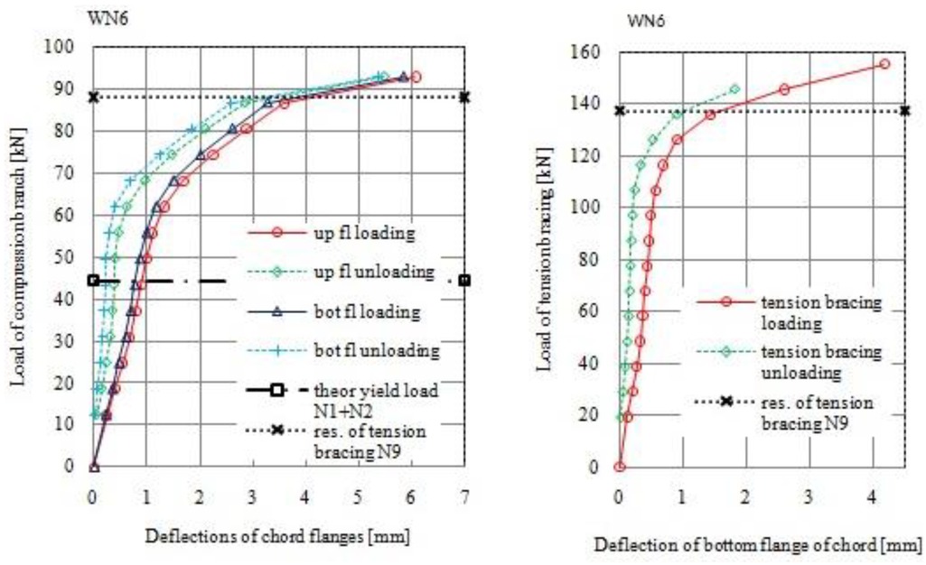
Load-deflection diagram for joint WN6 (β = 0,6)

Load-deflection diagram for joint WN7 (β = 0,6)

Load-deflection diagram for joint WN8 (β = 0,8)

Load-deflection diagram for joint WN9 (β = 0,8)
Theoretical resistances of joints
| Specimen | Theoretical component resistance [kN] | Minimum theoretical resistance [kN] | Mode of failure | ||||||
|---|---|---|---|---|---|---|---|---|---|
| N1+N2 | N3 | N4 | N6 | N7 | N8 | N9 | |||
| WN1 | 102,6 | - | 142,6 | 318,9 | 86,0 | 244,8 | 65,9 | 65,9 | N9 |
| WN2 | 148,3 | - | 182,6 | 374,4 | 125,6 | 371,1 | 137,2 | 137,2 | N9 |
| WN3 | 248,5 | 226,0 | 287,8 | 511,6 | 145,5 | 626,1 | 205,4 | 145,5 | N7 |
| WN4 | 30,7 | - | 74,1 | 191,3 | 112,3 | 244,8 | 65,9 | 30,7 | N1 |
| WN5 | 59,2 | - | 104,6 | 255,1 | 112,3 | 244,8 | 65,9 | 65,9 | N9 |
| WN6 | 44,4 | - | 120,5 | 224,6 | 110,8 | 371,1 | 137,2 | 44,4 | N1+N2 |
| WN7 | 85,7 | - | 166,5 | 299,5 | 110,8 | 371,1 | 137,2 | 85,7 | N1+N2 |
| WN8 | 85,7 | 62,0 | 162,1 | 307,0 | 145,0 | 626,1 | 205,4 | 62,0 | N3 |
| WN9 | 164,3 | 125,6 | 218,0 | 409,3 | 145,0 | 626,1 | 205,4 | 125,6 | N3 |
5 Conclusions
Main advantage of joints under research is that they bring the top and bottom flange if truss chord into load transfer, while commonly used welded joints only the top flange
However main drawback of such joints is weakness of chord member due to its slots and holes which could decrease resistance of this member in joint section
Tests results confirm that it is possible to eliminate the welding in connections between bracing and chord in studied herein N type RHS plug & play joints and reach resistance not less than welded ones.
The resistance of non-welded N RHS joint II generation is similar to face and bottom flange failure for non-welded T type RHS joint [2]. However N type joint of II generation has smaller deformations because of positive influence of the anchor blocks.
Specimens WN1-WN3, when chord is made with the compact section (λ0 = 20) reached full resistance and displacements of their chord flanges are small.
The anchor blocks ensure the transfer of force from the tension bracing to the chord with limited deflections and better integrate whole joint.
The theoretical estimations show that the anchor blocks have high resistance, exceeding other components.
6 Practical applications and future prospects
Non-welded N type RHS II generation joint are easy to manufacturing automation.
However the real manufacturing tolerances of the RHS members could be a problem to make the slots and holes in proper places. More advanced preparation of such operations will be needed.
These joints may bring closer the truss steel structures with large spans and oversized dimensions for their delivery in elements. They could be easy to make and cheap in transport and could significantly reduce the overall costs.
It is suggested to apply hot dip galvanizing as the corrosion protection of structures with such joints.
Structures with such joints can be mounted as temporary because they are easy to assemble and disassemble
References
[1] PN-EN 1993-1-8:2006 Eurocode 3: Design of steel structures – Part 1-8: Design of joints. 2006 PKN.Suche in Google Scholar
[2] Szlendak JK. Static resistance of laser-made, non-welded T RHS joint estimated using lite component method. J Construct Steel Res. 2019;159(5615):574–83.10.1016/j.jcsr.2019.05.005Suche in Google Scholar
[3] Szlendak JK. Innovative steel structure connections. Warsaw: PWN; 2019.Suche in Google Scholar
[4] Szlendak JK, Oponowicz PL. Resistance of RHS truss N type joints made by laser as non-welded plug & play connections. Lublin: Lublin University of Technology Press; 2013.10.35784/bud-arch.2156Suche in Google Scholar
[5] PN-EN 1993-1-1:2006 Eurocode 3: Design of steel structures – Part 1-1: General rules and rules for buildings. 2006 PKN.Suche in Google Scholar
[6] Bijlaard F, Brekelmans J. Plug and play type joints in steel and steel - concrete composite constructions, Proceedings of the Fifth International Conference on Advances in Steel Structures; 2007 Dec 5-7; Singapore. Research Publishing; 2007, Vol. I, pp. 75-83.Suche in Google Scholar
[7] Jaspart J, Weynand K. Extension of the Component Method to Joints in Tubular Construction, Proc. 9th Int Symp on Tubular Structures; 2001 April; Duesseldorf, Germany. pp. 517-523.Suche in Google Scholar
[8] Szlendak JK. P.L. Oponowicz P.L., Behaviour of one and double side non-welded T RHS compression truss joints, 7th International Conference on Steel & Aluminium Structures; 2011 July 13-15; Kuching, Malaysia. C. T. S. Beckett, C. E. Augarde. The effect of climate on the unconfined compressive strength of rammed earth. Unsaturated Soils: Research and Applications; 2012. pp. 287-292.10.3850/978-981-08-9247-0_rp041-icsas11Suche in Google Scholar
[9] Szlendak JK, Oponowicz PL. Experimental tests and numerical models of one and double side non-welded T RHS truss joints. 11th International Conference "Modern Building Materials, Structures and Techniques”, 2013 May 16-17; Vilnius, Lithuania.10.1016/j.proeng.2013.04.140Suche in Google Scholar
[10] Szlendak J.K., Szpyrka A., Resistance of tension brace in plug & play N shape RHS truss connection, Journal of Civil Engineering, Environment and Architecture JCEFA, 2018, t. XXXIII, z. 65.Suche in Google Scholar
© 2020 J. K. Szlendak and A. Szpyrka, published by De Gruyter
This work is licensed under the Creative Commons Attribution 4.0 International License.
Artikel in diesem Heft
- Regular Articles
- Fabrication of aluminium covetic casts under different voltages and amperages of direct current
- Inhibition effect of the synergistic properties of 4-methyl-norvalin and 2-methoxy-4-formylphenol on the electrochemical deterioration of P4 low carbon mold steel
- Logistic regression in modeling and assessment of transport services
- Design and development of ultra-light front and rear axle of experimental vehicle
- Enhancement of cured cement using environmental waste: particleboards incorporating nano slag
- Evaluating ERP System Merging Success In Chemical Companies: System Quality, Information Quality, And Service Quality
- Accuracy of boundary layer treatments at different Reynolds scales
- Evaluation of stabiliser material using a waste additive mixture
- Optimisation of stress distribution in a highly loaded radial-axial gas microturbine using FEM
- Analysis of modern approaches for the prediction of electric energy consumption
- Surface Hardening of Aluminium Alloy with Addition of Zinc Particles by Friction Stir Processing
- Development and refinement of the Variational Method based on Polynomial Solutions of Schrödinger Equation
- Comparison of two methods for determining Q95 reference flow in the mouth of the surface catchment basin of the Meia Ponte river, state of Goiás, Brazil
- Applying Intelligent Portfolio Management to the Evaluation of Stalled Construction Projects
- Disjoint Sum of Products by Orthogonalizing Difference-Building ⴱ
- The Development of Information System with Strategic Planning for Integrated System in the Indonesian Pharmaceutical Company
- Simulation for Design and Material Selection of a Deep Placement Fertilizer Applicator for Soybean Cultivation
- Modeling transportation routes of the pick-up system using location problem: a case study
- Pinless friction stir spot welding of aluminium alloy with copper interlayer
- Roof Geometry in Building Design
- Review Articles
- Silicon-Germanium Dioxide and Aluminum Indium Gallium Arsenide-Based Acoustic Optic Modulators
- RZ Line Coding Scheme With Direct Laser Modulation for Upgrading Optical Transmission Systems
- LOGI Conference 2019
- Autonomous vans - the planning process of transport tasks
- Drivers ’reaction time research in the conditions in the real traffic
- Design and evaluation of a new intersection model to minimize congestions using VISSIM software
- Mathematical approaches for improving the efficiency of railway transport
- An experimental analysis of the driver’s attention during train driving
- Risks associated with Logistics 4.0 and their minimization using Blockchain
- Service quality of the urban public transport companies and sustainable city logistics
- Charging electric cars as a way to increase the use of energy produced from RES
- The impact of the truck loads on the braking efficiency assessment
- Application of virtual and augmented reality in automotive
- Dispatching policy evaluation for transport of ready mixed concrete
- Use of mathematical models and computer software for analysis of traffic noise
- New developments on EDR (Event Data Recorder) for automated vehicles
- General Application of Multiple Criteria Decision Making Methods for Finding the Optimal Solution in City Logistics
- The influence of the cargo weight and its position on the braking characteristics of light commercial vehicles
- Modeling the Delivery Routes Carried out by Automated Guided Vehicles when Using the Specific Mathematical Optimization Method
- Modelling of the system “driver - automation - autonomous vehicle - road”
- Limitations of the effectiveness of Weigh in Motion systems
- Long-term urban traffic monitoring based on wireless multi-sensor network
- The issue of addressing the lack of parking spaces for road freight transport in cities - a case study
- Simulation of the Use of the Material Handling Equipment in the Operation Process
- The use of simulation modelling for determining the capacity of railway lines in the Czech conditions
- Proposals for Using the NFC Technology in Regional Passenger Transport in the Slovak Republic
- Optimisation of Transport Capacity of a Railway Siding Through Construction-Reconstruction Measures
- Proposal of Methodology to Calculate Necessary Number of Autonomous Trucks for Trolleys and Efficiency Evaluation
- Special Issue: Automation in Finland
- 5G Based Machine Remote Operation Development Utilizing Digital Twin
- On-line moisture content estimation of saw dust via machine vision
- Data analysis of a paste thickener
- Programming and control for skill-based robots
- Using Digital Twin Technology in Engineering Education – Course Concept to Explore Benefits and Barriers
- Intelligent methods for root cause analysis behind the center line deviation of the steel strip
- Engaging Building Automation Data Visualisation Using Building Information Modelling and Progressive Web Application
- Real-time measurement system for determining metal concentrations in water-intensive processes
- A tool for finding inclusion clusters in steel SEM specimens
- An overview of current safety requirements for autonomous machines – review of standards
- Expertise and Uncertainty Processing with Nonlinear Scaling and Fuzzy Systems for Automation
- Towards online adaptation of digital twins
- Special Issue: ICE-SEAM 2019
- Fatigue Strength Analysis of S34MnV Steel by Accelerated Staircase Test
- The Effect of Discharge Current and Pulse-On Time on Biocompatible Zr-based BMG Sinking-EDM
- Dynamic characteristic of partially debonded sandwich of ferry ro-ro’s car deck: a numerical modeling
- Vibration-based damage identification for ship sandwich plate using finite element method
- Investigation of post-weld heat treatment (T6) and welding orientation on the strength of TIG-welded AL6061
- The effect of nozzle hole diameter of 3D printing on porosity and tensile strength parts using polylactic acid material
- Investigation of Meshing Strategy on Mechanical Behaviour of Hip Stem Implant Design Using FEA
- The effect of multi-stage modification on the performance of Savonius water turbines under the horizontal axis condition
- Special Issue: Recent Advances in Civil Engineering
- The effects of various parameters on the strengths of adhesives layer in a lightweight floor system
- Analysis of reliability of compressed masonry structures
- Estimation of Sport Facilities by Means of Technical-Economic Indicator
- Integral bridge and culvert design, Designer’s experience
- A FEM analysis of the settlement of a tall building situated on loess subsoil
- Behaviour of steel sheeting connections with self-drilling screws under variable loading
- Resistance of plug & play N type RHS truss connections
- Comparison of strength and stiffness parameters of purlins with different cross-sections of profiles
- Bearing capacity of floating geosynthetic encased columns (GEC) determined on the basis of CPTU penetration tests
- The effect of the stress distribution of anchorage and stress in the textured layer on the durability of new anchorages
- Analysis of tender procedure phases parameters for railroad construction works
- Special Issue: Terotechnology 2019
- The Use of Statistical Functions for the Selection of Laser Texturing Parameters
- Properties of Laser Additive Deposited Metallic Powder of Inconel 625
- Numerical Simulation of Laser Welding Dissimilar Low Carbon and Austenitic Steel Joint
- Assessment of Mechanical and Tribological Properties of Diamond-Like Carbon Coatings on the Ti13Nb13Zr Alloy
- Characteristics of selected measures of stress triaxiality near the crack tip for 145Cr6 steel - 3D issues for stationary cracks
- Assessment of technical risk in maintenance and improvement of a manufacturing process
- Experimental studies on the possibility of using a pulsed laser for spot welding of thin metallic foils
- Angular position control system of pneumatic artificial muscles
- The properties of lubricated friction pairs with diamond-like carbon coatings
- Effect of laser beam trajectory on pocket geometry in laser micromachining
- Special Issue: Annual Engineering and Vocational Education Conference
- The Employability Skills Needed To Face the Demands of Work in the Future: Systematic Literature Reviews
- Enhancing Higher-Order Thinking Skills in Vocational Education through Scaffolding-Problem Based Learning
- Technology-Integrated Project-Based Learning for Pre-Service Teacher Education: A Systematic Literature Review
- A Study on Water Absorption and Mechanical Properties in Epoxy-Bamboo Laminate Composite with Varying Immersion Temperatures
- Enhancing Students’ Ability in Learning Process of Programming Language using Adaptive Learning Systems: A Literature Review
- Topical Issue on Mathematical Modelling in Applied Sciences, III
- An innovative learning approach for solar power forecasting using genetic algorithm and artificial neural network
- Hands-on Learning In STEM: Revisiting Educational Robotics as a Learning Style Precursor