Comparison of strength and stiffness parameters of purlins with different cross-sections of profiles
-
 and
and

Abstract
The article presents comparative analyzes aimed at determining the optimal cross-section used in cold-formed steel purlins. The geometrical characteristics, bending resistance and self-weight of channel, zeta and hat cross-sections were compared. The calculations were made using Dlubal SHAPE-THIN software for the bending by the main axis y-y and z-z. The characteristics for the gross and effective cross-section were determined. Based on the first stage analyzes, a significant decrease in cross-sectional bending resistant was observed as a result of a local buckling. The solution to this problem may be the use of intermediate stiffeners. In the second stage, analysis of the impact of the intermediate stiffeners’ locations on the characteristics of hat sections were conducted. Additional intermediate stiffeners on the webs, on the upper chord, and on the webs and upper chord (together) were considered. A significant effect on the bending resistant with a small increase in the element’s self-weight has been demonstrated. In the third stage, the characteristics of a channel, zeta and hat profile with intermediate longitudinal stiffener in the middle of the web were compared. The performed analyzes demonstrated that the hat cross-section shows a significant advantage in bending by the main axis z-z. This advantage can be used in case of lack of protection against lateral torsional buckling and a larger degree of roof slope.
1 Introduction
In typical structure of steel single story industrial building purlins are usually members in roof structure used as a support of the roof decking or sheeting. In classical solutions they are made of hot-rolled sections (IPE) but recent developments in the field of construction aims at decrease self-weight of members by the using the cold-formed section (zeta section, channel section), which are described in [1, 2, 3] and [4] or [5]. Making of new types of cold formed profiles is caused by the development of technology of fabricate thin walled structures and the freedom in the shaping of cross-section. Difficulties appear due to complicated calculating procedures used for the verifications of limit states of thin-walled constructions. Members with slender cross-section plates in bending and axial compression are prone to local buckling,which must be considered in calculating of effective section properties. These characteristics are determined according to [6]. However, these are quite laborious and time-consuming iterative calculation procedures. The calculations recommended by the Eurocode procedure are as follows:

Flow chart: Calculation of effective section properties according to EC-1993-1-3
The technology of the production enables the increase of the stability of cross-section plates by changes in the geometry of the section for purposes of the increase of the efficiency of the material consumption, [7, 8] and [9]. Beneficial solution is the introduction of additional bends and groove as an intermediate and edge stiffeners. In this paper issues concerning design of cold-formed purlin with hat cross-sectional without stiffeners, with flange stiffeners and with together web and flange stiffeners are presented. The implementation of these stiffeners is aimed at:
stiffening of the walls of the element,
changing the cross-sectional class of the element to a more favorable one,
increase (slightly) the cross-sectional area of the element.
Changing the geometric characteristics of the cross-section is very important taking into account checking its resistance and stability of the element. In order to determine the abovementioned characteristics, computer aided design methods were used -what was described in the article. The SHAPE-THIN computer software was used to facilitate and accelerate calculations and analyzes. Computer aided calculations also enabled the transfer of computational models and calculation results in electronic form to other kinde of software. The article also aims to promote computer calculations based on Fine Element Analysis, as a complement to and in some cases alternatives to manual calculations - performed using classical methods. Computer methods in the design and analysis of cold-bent components have been flavored recently. Currently, there are more and more softwares for this type of analysis, and their use in this article is proof of this. The calculations were carried out according to the following scheme:

Flow chart: Calculation of effective section properties using AutoCad and SHAPE-THIN software
2 Analysis of the cross-sections of elements
2.1 Analysed cross-section
Cold-formed purlins are often made using zeta and channel profiles. These types of profiles are easy to produce and their self-weight is relatively small compared to hot-rolled members. To disadvantages of these elements can be counted relatively low resistance in bending by the main axis z-z of cross-section and vulnerability to local buckling (sections class 4). As an alternative to zeta and channel profiles can be used hat profiles. Though their mass is greater than zeta and channel profiles, their bending strength by the main z-z axis of cross-section is much more than earlier elements. To compare geometrical characteristics and resistance of profiles with hat, channel and zeta cross-section, Figure 3 and Table 1, computational analysis were carried out.

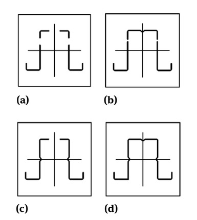
View of cold-formed non stiffened cross-section: a) hat profile, b) channel profile, c) zeta profile
Dimensions of analysed profiles
| Name | hat profile | U- profile | zeta profile | |
|---|---|---|---|---|
| Height | h [mm] | 200 | 200 | 220 |
| Upper chord | a [mm] | 140 | - | - |
| Bottom chord | b [mm] | 70 | 70 | 55/63 |
| Stiffener | c [mm] | 30 | 25 | 25 |
| Sheet thickness | t [mm] | 2 | 3 | 2 |
| Internal radius | r [mm] | 2,63 | 2,63 | 2,63 |
The following parameters were obtained during calculations:
the area of the gross cross-section Agross,
class of cross-section in bending by the main axis y-y,
section modulus of the gross cross-section with regard to the y-y axis Wy,el,
section modulus of the effective cross-section with regard to the y-y axis Wy,eff ,
resistance of cross-section in bending by the main axis y-y MRd,y,eff ,
class of cross-section in bending by the main axis z-z
section modulus of the gross cross-section with regard to the z-z axis Wz,el,
section modulus of the effective cross-section with regard to the z-z axis Wz,eff ,
resistance of cross-section in bending by the main axis z-z MRd,z,eff .
2.2 Computational analysis
2.2.1 Comparison of geometrical characteristics of hat, zeta and channel profiles
All calculations were made using Dlubal SHAPE-THIN software, [10]. The computer software SHAPE-THIN determines section properties of open and closed thinn-walled cross-section and performs the stress analysis. Main features of the software:
modeling of the cross-section via elements, sections, arcs and point elements,
expandable library of material properties, yield strengths, and limit stresses,
possibility obtaining of section properties of open, closed or non-connected cross-sections,
possibility calculating effective properties of cross-sections consisting of different materials,
possibility determinating of weld stresses in fillet welds,
stress analysis and design of cross-sections taking into account influence of primary and secondary torsion,-
checking of (c/t) ratios,
possibility calculating of effective cross-sections according to [11],
classification of elements cross-section according to [12].
SHAPE-THIN calculates all relevant cross-section properties, including plastic limit forces and moments. In addition to the elastic stress analysis, you can perform the plastic analysis taking into account interaction of internal forces for any type cross-section shape. The plastic designing with interaction is carried out according to the Simplex Method. There is possibility choosing the yield hypothesis according to Tresca or von Mises. It is possible to calculate the section properties and stresses of the effective cross-section according to [6] and [11] or [12]. Cross-section classification considers the available combination of internal forces.
The shape (geometry) of profile cross-sections under bending were modeled using linear or arc elements with thickness 2mm. All calculations were made according to [6, 11, 12] and [13]. Because of preliminary types of this calculations, distortional buckling not was taken into account in analysis. As a static schema of the analysed elements, a self-supported single-span beam, was taken into account. The method of supporting beam at its ends allowed the beam to rotate freely at the horizontal axis and secured the ends of the beam against torsion. The beam was loaded by a continuous load, uniformly distributed, in and out of the plane of y-y main axis. Results of calculations were presented in Table 2 and Figure 4, 5 and 6.

Resistance of cross-section in bending

a) Class of cross-section, b) Self-weight of profiles
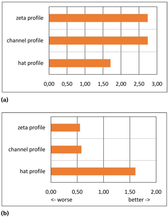
a) The ratio MRd,y,eff / self-weight of the profile, b) The ratio MRd,z,eff / self-weight of the profile
Results of calculations, elements without longitude stiffeners
| channel 200×2 | zeta 220×2 | hat 200×2 | ||
|---|---|---|---|---|
| Agross | [cm2] | 7,56 | 7,52 | 14,49 |
| [*] | - | 3 | 4 | 4 |
| Wy,el | [cm3] | 45,88 | 46,44 | 81,91 |
| Wy,eff | [cm3] | 45,88 | 45,62 | 54,72 |
| [*] | - | 4 | 4 | 4 |
| Wz,el | [cm3] | 10,95 | 9,20 | 69,33 |
| Wz,eff | [cm3] | 9,69 | 9,19 | 51,44 |
| MRd,y | [kNm] | 16,29 | 16,49 | 29,08 |
| MRd,y,eff | [kNm] | 16,29 | 16,20 | 19,43 |
| MRd,z | [kNm] | 3,89 | 3,27 | 24,61 |
| MRd,z,eff | [kNm] | 3,44 | 3,26 | 18,26 |
| [*] | [kg/m] | 5,93 | 5,90 | 11,37 |
The following results have been registered and saved during calculations:
self-weight of profile
class section of profile,
geometricach characteristics gross cross-section (area, moments of inertia, section modulus and effective lengths of croos-setion plates),
geometrical characteristics effective cross-section (as above),
the extremal stress values of cross-section.
All this results were calculated automatically and next saved on on computer mass storage systems as a as files with calculation data. Next, this data were imported to calculations software (calculation sheet). then they were sorted in tables and presented in the form of bar charts and exported to the word procesor.
Based on results of calculations, following conclusion can be made:
In case of bending by the main axis y-y, only channel profile 200×2 cross-section is classified to 3 class; zeta 220×2 and hat 200×2 profiles counts to 4 class in bending.
In case of bending by the main axis z-z all profiles are classified to 4 class in bending.
The biggest difference between values MRd,y and MRd,y,eff or MRd,z and MRd,z,eff is for hat profiles; this is due to the fact that the cross section belongs to class 4 in bending. Making stiffeners on the wall of the profile can reduce the cross-section class and help to reduce the difference (increasing values of resistance of effective cross-section in bending MRd,y,eff or MRd,z,eff ).
The value of the ratio of resistance of cross-section in bending by the main axis y-y to self-weight of profile is rather adverse for the hat profiles – because of greater self-weight these profile than zeta and channel profiles, and reduction of resistance due to class 4 cross-section. But in case of bending by the main axis z-z axis of cross-section, the value of this coefficient is more favorable than for other profiles.
All conclusions provided above, may be the reason to make longitudinal profile stiffeners, to reduce class of cross-section and increasing their bending strength values.
2.2.2 Influence of numbers of longitude stiffeners on geometrical characteristics of hat cross-sections
Taking into account conclusions written above, the second stage analysis was made. In this calculations, influence of numbers of stiffeners on geometrical characteristics and resistance of hat cross-sections were obtained. Four types of profiles were taken into account, Figure 7:
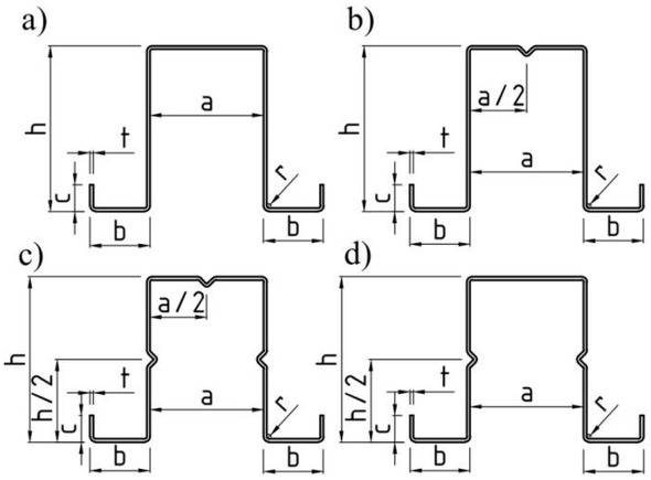
View of analysed hat profiles: a) cross-section without longitudinal stiffeners, b) cross-section with stiffener on upper chord, c) cross-section with stiffeners on webs, d) cross-section with stiffeners on upper chord and webs
profiles without longitudinal stiffeners,
profiles with stiffener on upper chord,
profiles with stiffeners on webs,
profiles with stiffeners on upper chord and webs.
The resistance in bending in and out of plane of y-y main axis of cross-section were determined and compared.
As previously, all geometrical characteristics of cross-section of hat profiles and class of cross-section were calculated using SHAPE-THIN Dlubal software. Results of calculationswere presented in Table 3. View of effective cross-section area of analysed profiles was presented on Figure 8 and 9.
View of effective cross-section area of analysed hat profiles – bending by the main axis y-y: a) profile without longitudinal stiffeners, b) profile with stiffener on upper chord, c) profile with stiffeners on webs, d) profile with stiffeners on upper chord and webs

View of effective cross-section area of analysed hat profiles – bending by the main axis z-z: a) profile without longitudinal stiffeners, b) profile with stiffener on upper chord, c) profile with stiffeners on webs, d) profile with stiffeners on upper chord and webs
Results of calculations, hat profiles with longitude stiffeners
| hat 200×2 | hat 200×2U | hat 200×2W | hat 200×2UW | |
|---|---|---|---|---|
| Agross [cm2] | 14,49 | 14,62 | 14,75 | 14,88 |
| [*] | 4 | 4 | 4 | 3 |
| Wy,el [cm3] | 81,91 | 83,32 | 82,00 | 83,41 |
| Wy,eff [cm3] | 54,72 | 82,48 | 59,84 | 83,41 |
| [**] | 4 | 4 | 4 | 4 |
| Wz,el [cm3] | 69,33 | 69,33 | 69,76 | 69,76 |
| Wz,eff [cm3] | 51,44 | 51,50 | 63,92 | 63,94 |
| MRd,y [kNm] | 29,08 | 29,58 | 29,11 | 29,61 |
| MRd,y,eff [kNm] | 19,43 | 29,28 | 21,24 | 29,61 |
| MRd,z [kNm] | 24,61 | 24,61 | 24,76 | 24,76 |
| MRd,z,eff [kNm] | 18,26 | 18,28 | 22,69 | 22,70 |
| [***] [kg/m] | 11,37 | 11,48 | 11,58 | 11,68 |
Based on results of calculations, following conclusions can be made:
Making longitudinal stiffeners in a very small way increases the weight of the profile – no more than 3%.
In case of bending by the main axis y-y of cross-section, stiffeners made only on upper chord or only on webs do not changing class of cross-section. Just making stiffeners together on upper chord and webs, reduced class of cross-section in bending.
In case of bending by the main axis z-z of cross-section, stiffeners made on upper chord and on webs not changing class of cross-section. Cross-section still remains in class 4 in bending.
Making of longitudinal stiffeners causes an increasing of effective section module of profiles and its bending resistance, Figure 10. In case profiles making of 2 mm sheet thickness, the most effective is making stiffeners on webs or webs and upper chord – this causes an increase the value of resistance of bending by the main axis y-y about 50%.

a) Resistance of cross-section in bending, b) percentage increase bending capacity of cross-section in relation to the non-stiffened profile
2.2.3 Comparison of geometrical characteristics of cross-sections of hat, channel and zeta profiles with longitudinal stiffeners
In the third part of calculations comparative analysis was carried out. In this analysis three types of cross-sections were compared: hat profiles, channel profiles and zeta profiles with stiffeners on webs. The stiffeners on upper chord of profiles were neglected. It was due to the difficulty of fixing the roof sheeting to the upper chord of purlin with its stiffeners. Like previously, two kind of load were taking into consideration: bending by the main axis y-y or z-z of cross-section. Due to the preliminary nature of calculations, as a static schema of the analysed elements, a single-span beam, self-supportedwas taken into account. View of effective cross-section of profiles (in both cases of the load) was presented on Figure 9 and 11. Results of analysis were presented in Table 4 and Figure 12.

View of effective cross-section area of analysed profiles with stiffener on the web: a) channel profile, bending by the main axis y-y, b) channel profile, bending by the main axis z-z, c) zeta profile, bending by the main axis y-y, d) zeta profile, bending by the main axis z-z

a) Section modulus of the effective cross-section with regard to the y-y axis Wy,eff , b) Section modulus of the effective cross-section with regard to the z-z axis Wz,eff
3 Final conclusions
Based on the results of the calculations described above, the following main conclusion can be formulated:
The self-weight of purlins made of hat profiles is about two times more than channel and zeta profiles with similar geometrical dimensions (the high of the profile).
Purlins made of hat profiles are characterized by a relatively high bending resistance with bi-axial bending. For this reason, it is recommended to use them in roof structure with a large roof slope angle.
Making of longitudinal stiffeners causes a decreasing of class of cross-section and an increasing of effective section module of profiles and its bending resistance.
Due to the difficulty of fixing the roof sheeting to the upper chord of purlin, making longitude stiffener on this part of element can be not recommended for execution.
Finally it can be said that cold-formed steel purlins with hat cross-section can be an alternative to purlins with channel and zeta cross-sections and hot-rolled members.
The above-mentioned conclusions relate to purlins, which are secured against lateral torsional buckling with a roof sheeting plate. In the case of lack of protection against lateral torsional buckling and a larger degree of roof slope, hat cross-sections may be more advantageous. However, this requires further calculations. The distortional buckling, global stability and the other static schema of purlins should be taken into consideration in further calculations.
The article was developed as part of the research project implemented in cooperation with the Rzeszów University of Technology and the company FPUH KOBEX, as part of the activity: Regional Operational Program of the Podkarpackie Voivodeship for 2014-2020, Priority axis: I Competitive and innovative economy, Measure: 1.2 Industrial research, development works and their implementation, Project type: Research and Development B+R.
References
[1] Wang L, Young B. Cold-Formed Steel Channel Sections with Web Stiffeners Subjected to Local and Distortional Buckling – Part I: Tests and Finite Elements Analysis, International Specialty Conference on Cold-Formed Steel Structures. 1., 2014.Search in Google Scholar
[2] Cucu V, Constantin D, Buliga DI. Structural efficiency of cold-formed steel purlins, International Conference Knowledge-Based Organization Vol. XXI. No 3., 2015, https://doi.org/10.1515/kbo-2015-013710.1515/kbo-2015-0137Search in Google Scholar
[3] Tan J, Susila A. Flexural strength performance and buckling mode prediction of cold-formed steel (C section). Procedia Eng. 2015;125:979–86.10.1016/j.proeng.2015.11.151Search in Google Scholar
[4] Papangelis JP, Hancock GJ, Trahair NS. Computer Design of Cold-Formed C- and Z-Section Purlins. J Construct Steel Res. 1998 Apr-Jun;46(1-3):169–71.10.1016/S0143-974X(98)00085-6Search in Google Scholar
[5] Qasim TM, Al-Zaidee SR. Experimental Investigation for Non and Partially Composite Cold-Formed Steel Floor Beams, Civil. Eng J (NY). •••;5(6): https://doi.org/10.28991/cej-2019-0309134110.28991/cej-2019-03091341Search in Google Scholar
[6] EN 1993-1-3: Eurocode 3: Design of steel structures – Part 1-3: General rules – Supplementary rules for cold-formed members and sheeting. European Committee for Standardization, Brussels, 2006Search in Google Scholar
[7] Bródka J, Broniewicz M, Giżejowski M. Kształtowniki gięte. Poradnik projektanta. Rzeszów: Polskie Wydawnictwo Techniczne; 2006.Search in Google Scholar
[8] Bródka J. Łubiński M., Lekkie konstrukcje stalowe. Warszawa: Arkady; 1978.Search in Google Scholar
[9] Abdi R., Yazdi N. A., Effects of aspect ratio and plate thickness on the behavior of unstiffened steel-plate shear walls with pinned and rigid connections, Journal Article published 4 Jul 2018 in Civil Engineering Journal volume 4 issue 6 on page 1383, https://doi.org/https://doi.org/10.28991/cej-030918010.28991/cej-0309180Search in Google Scholar
[10] Dlubal SH. https://www.dlubal.com/plSearch in Google Scholar
[11] EN 1993-1-5 (2006): Eurocode 3: Design of steel structures – Part 1-5: General rules – Plated structural elements. European Committee for Standardization, Brussels.Search in Google Scholar
[12] EN 1993-1-1: Eurocode 3: Design of steel structures – Part 1-1: General rules for buildings. European Committee for Standardization, Brussels, 2005Search in Google Scholar
[13] ECCS Technical Committee 7 Cold-formed Steel Worked examples according to EN 1993-1-3 Eurocode 3, Part 1-3Search in Google Scholar
© 2020 A. Wojnar and K. Sieńkowska, published by De Gruyter
This work is licensed under the Creative Commons Attribution 4.0 International License.
Articles in the same Issue
- Regular Articles
- Fabrication of aluminium covetic casts under different voltages and amperages of direct current
- Inhibition effect of the synergistic properties of 4-methyl-norvalin and 2-methoxy-4-formylphenol on the electrochemical deterioration of P4 low carbon mold steel
- Logistic regression in modeling and assessment of transport services
- Design and development of ultra-light front and rear axle of experimental vehicle
- Enhancement of cured cement using environmental waste: particleboards incorporating nano slag
- Evaluating ERP System Merging Success In Chemical Companies: System Quality, Information Quality, And Service Quality
- Accuracy of boundary layer treatments at different Reynolds scales
- Evaluation of stabiliser material using a waste additive mixture
- Optimisation of stress distribution in a highly loaded radial-axial gas microturbine using FEM
- Analysis of modern approaches for the prediction of electric energy consumption
- Surface Hardening of Aluminium Alloy with Addition of Zinc Particles by Friction Stir Processing
- Development and refinement of the Variational Method based on Polynomial Solutions of Schrödinger Equation
- Comparison of two methods for determining Q95 reference flow in the mouth of the surface catchment basin of the Meia Ponte river, state of Goiás, Brazil
- Applying Intelligent Portfolio Management to the Evaluation of Stalled Construction Projects
- Disjoint Sum of Products by Orthogonalizing Difference-Building ⴱ
- The Development of Information System with Strategic Planning for Integrated System in the Indonesian Pharmaceutical Company
- Simulation for Design and Material Selection of a Deep Placement Fertilizer Applicator for Soybean Cultivation
- Modeling transportation routes of the pick-up system using location problem: a case study
- Pinless friction stir spot welding of aluminium alloy with copper interlayer
- Roof Geometry in Building Design
- Review Articles
- Silicon-Germanium Dioxide and Aluminum Indium Gallium Arsenide-Based Acoustic Optic Modulators
- RZ Line Coding Scheme With Direct Laser Modulation for Upgrading Optical Transmission Systems
- LOGI Conference 2019
- Autonomous vans - the planning process of transport tasks
- Drivers ’reaction time research in the conditions in the real traffic
- Design and evaluation of a new intersection model to minimize congestions using VISSIM software
- Mathematical approaches for improving the efficiency of railway transport
- An experimental analysis of the driver’s attention during train driving
- Risks associated with Logistics 4.0 and their minimization using Blockchain
- Service quality of the urban public transport companies and sustainable city logistics
- Charging electric cars as a way to increase the use of energy produced from RES
- The impact of the truck loads on the braking efficiency assessment
- Application of virtual and augmented reality in automotive
- Dispatching policy evaluation for transport of ready mixed concrete
- Use of mathematical models and computer software for analysis of traffic noise
- New developments on EDR (Event Data Recorder) for automated vehicles
- General Application of Multiple Criteria Decision Making Methods for Finding the Optimal Solution in City Logistics
- The influence of the cargo weight and its position on the braking characteristics of light commercial vehicles
- Modeling the Delivery Routes Carried out by Automated Guided Vehicles when Using the Specific Mathematical Optimization Method
- Modelling of the system “driver - automation - autonomous vehicle - road”
- Limitations of the effectiveness of Weigh in Motion systems
- Long-term urban traffic monitoring based on wireless multi-sensor network
- The issue of addressing the lack of parking spaces for road freight transport in cities - a case study
- Simulation of the Use of the Material Handling Equipment in the Operation Process
- The use of simulation modelling for determining the capacity of railway lines in the Czech conditions
- Proposals for Using the NFC Technology in Regional Passenger Transport in the Slovak Republic
- Optimisation of Transport Capacity of a Railway Siding Through Construction-Reconstruction Measures
- Proposal of Methodology to Calculate Necessary Number of Autonomous Trucks for Trolleys and Efficiency Evaluation
- Special Issue: Automation in Finland
- 5G Based Machine Remote Operation Development Utilizing Digital Twin
- On-line moisture content estimation of saw dust via machine vision
- Data analysis of a paste thickener
- Programming and control for skill-based robots
- Using Digital Twin Technology in Engineering Education – Course Concept to Explore Benefits and Barriers
- Intelligent methods for root cause analysis behind the center line deviation of the steel strip
- Engaging Building Automation Data Visualisation Using Building Information Modelling and Progressive Web Application
- Real-time measurement system for determining metal concentrations in water-intensive processes
- A tool for finding inclusion clusters in steel SEM specimens
- An overview of current safety requirements for autonomous machines – review of standards
- Expertise and Uncertainty Processing with Nonlinear Scaling and Fuzzy Systems for Automation
- Towards online adaptation of digital twins
- Special Issue: ICE-SEAM 2019
- Fatigue Strength Analysis of S34MnV Steel by Accelerated Staircase Test
- The Effect of Discharge Current and Pulse-On Time on Biocompatible Zr-based BMG Sinking-EDM
- Dynamic characteristic of partially debonded sandwich of ferry ro-ro’s car deck: a numerical modeling
- Vibration-based damage identification for ship sandwich plate using finite element method
- Investigation of post-weld heat treatment (T6) and welding orientation on the strength of TIG-welded AL6061
- The effect of nozzle hole diameter of 3D printing on porosity and tensile strength parts using polylactic acid material
- Investigation of Meshing Strategy on Mechanical Behaviour of Hip Stem Implant Design Using FEA
- The effect of multi-stage modification on the performance of Savonius water turbines under the horizontal axis condition
- Special Issue: Recent Advances in Civil Engineering
- The effects of various parameters on the strengths of adhesives layer in a lightweight floor system
- Analysis of reliability of compressed masonry structures
- Estimation of Sport Facilities by Means of Technical-Economic Indicator
- Integral bridge and culvert design, Designer’s experience
- A FEM analysis of the settlement of a tall building situated on loess subsoil
- Behaviour of steel sheeting connections with self-drilling screws under variable loading
- Resistance of plug & play N type RHS truss connections
- Comparison of strength and stiffness parameters of purlins with different cross-sections of profiles
- Bearing capacity of floating geosynthetic encased columns (GEC) determined on the basis of CPTU penetration tests
- The effect of the stress distribution of anchorage and stress in the textured layer on the durability of new anchorages
- Analysis of tender procedure phases parameters for railroad construction works
- Special Issue: Terotechnology 2019
- The Use of Statistical Functions for the Selection of Laser Texturing Parameters
- Properties of Laser Additive Deposited Metallic Powder of Inconel 625
- Numerical Simulation of Laser Welding Dissimilar Low Carbon and Austenitic Steel Joint
- Assessment of Mechanical and Tribological Properties of Diamond-Like Carbon Coatings on the Ti13Nb13Zr Alloy
- Characteristics of selected measures of stress triaxiality near the crack tip for 145Cr6 steel - 3D issues for stationary cracks
- Assessment of technical risk in maintenance and improvement of a manufacturing process
- Experimental studies on the possibility of using a pulsed laser for spot welding of thin metallic foils
- Angular position control system of pneumatic artificial muscles
- The properties of lubricated friction pairs with diamond-like carbon coatings
- Effect of laser beam trajectory on pocket geometry in laser micromachining
- Special Issue: Annual Engineering and Vocational Education Conference
- The Employability Skills Needed To Face the Demands of Work in the Future: Systematic Literature Reviews
- Enhancing Higher-Order Thinking Skills in Vocational Education through Scaffolding-Problem Based Learning
- Technology-Integrated Project-Based Learning for Pre-Service Teacher Education: A Systematic Literature Review
- A Study on Water Absorption and Mechanical Properties in Epoxy-Bamboo Laminate Composite with Varying Immersion Temperatures
- Enhancing Students’ Ability in Learning Process of Programming Language using Adaptive Learning Systems: A Literature Review
- Topical Issue on Mathematical Modelling in Applied Sciences, III
- An innovative learning approach for solar power forecasting using genetic algorithm and artificial neural network
- Hands-on Learning In STEM: Revisiting Educational Robotics as a Learning Style Precursor