Simulation for Design and Material Selection of a Deep Placement Fertilizer Applicator for Soybean Cultivation
-
Iaroslav Patuk
 ,
Hideo Hasegawa
,
Hideo Hasegawa

Abstract
The optimal design of a subsoiler implement is a complex work that includes optimal design, material properties, structural reliability, random variables, soil properties, soil tillage equipment, and optimum safety measures. The main objectives of this study were to design and simulate the deep placement fertilizer applicator (DPFA) by using the finite element method (FEM). FEM simulation software was used to select the optimum material properties and improve the safety factor by considering a range of loads on DPFA. Three applied forces in a static simulation (4500, 5000 and 6000 N) were considered as were three application depths of fertilizers (0.15, 0.20, and 0.25 m), to improve the safety measures of the design. The simulation results showed that the best material property for DPFA is the AISI 4135 QT carbon steel materials. This yields a high strength of 780MPa and an ultimate tensile strength of 950 MPa (Young’s Modulus of 207 GPa and with Poisson’s Ratio of 0.33). The static simulation for 6000 N shows that the DPFA model had a maximum stress and strain of 379.9 MPa and 25.6×10⁻⁴ mm/mm respectively, with a contact pressure of 207 MPa, and a maximum displacement of 3.1 mm. The study results can provide theoretical and technical support for the development of agricultural tools, especially for DPFA in selecting optimum material properties and improving safety factors.
1 Introduction
The development of new technologies and methods in crop growth is one of the important roles in sustainable agriculture. To do this, farmers in developing countries are looking for new technology to increase labor-saving, crop yields and the quality thereof, by reducing the amount of fertilizer used. In addition, this should decrease environmental damage to the atmosphere and water [1].
Deep placement fertilizer technology (DPFT) is an innovative and cost-effective practice, which serves not only in the reduction of wastage and excessive use of fertilizer but also in the even distribution of nutrients in the soil and the mitigation of the negative impact on the environment induced by fertilizer [2]. Furthermore, the subsoil tillage may greatly improve crop growth and increase the utilization rate of soil nutrients by providing free air and water exchange through the tillage of compacted soil layers [3].
In several developed and developing countries, especially Japan, China and Bangladesh, the multiple benefits of DPFT have been confirmed by experts. In Japan, it has been proven that the deep application of controlled-release fertilizers such as coated urea and lime nitrogen, as well as phosphorus and potassium at depths of 20 cm, has a positive effect on growth, seed quality and the yield of soybean plants. This is achieved by the promotion of fertilizer fixation, especially through the reproductive stages (R1 – R6) [4, 5, 6, 7]. In China and Bangladesh, several types of research endeavors were carried out on nitrogen fertilizer efficiency, the environmental impacts of this fertilizer, and the crop productivity of deep placement application in rice fields. It has been established that deep fertilizer placement from 5 to 20 cm have significantly increased overall nitrogen use efficiency by 20 – 50% and grain yields by 5 – 25% on average compared to broadcast fertilizer application (shallow soil application). In addition, nitrogen deep
placement application significantly decreased mean nitrogen concentration by 60%, and pH by3%in floodwater [8, 9, 10].
Besides the benefits of DPFT, labor-intensive work is still required for deep fertilizer placement in some cases, whether it be of a small or large scale of agricultural practices. Therefore, to implement DPFT during the sowing of crops in different scales of agriculture, the development of mechanized deep fertilizer technologies, and new optimized deep placement fertilizer applicators (DPFA), are necessary to be developed for subsoiling fertilizer application, and tillage purposes [8]. Consequently, deep placement fertilizer machinery and subsoilers have been successfully developed and improved recently. For example, the research by Fujii et al. [1] was the evaluation of tillage efficiency and power requirements of a rotary tillage implement combined with a deep placement fertilizer applicator. Zeng et al. discussed in [11] the method of modeling a deep tillage tool with heterogeneous soil by a discrete element model (DEM). It was found that the better performance of the deep tillage tool achieved at 5 – 20 mm deeper than the hardpan layer, where it has a greater bulk density than the topsoil layer. Hang et al. [12] developed a subsoiling model by DEM for soil disturbance in different tine spacing of the subsoiler. It was later verified in a discrete element simulation, as well as in a field test with a loamy clay soil. Ebrahimi et al. [13] and Topakci et al. [14] conducted practical research on life estimation and optimization of a deep tillage tool by the Finite Element Method (FEM) and through the performance of field experiments. Sandakov et al. [15] optimized a chisel plow model by decreasing the mass and increasing its service life in an FEM (simulation software). Moreover, several interesting studies on developing deep placement fertilizer applicators and subsoilers were published [16, 17, 18, 19]. However, the studies of developed machinery and subsoilers still have limited applied knowledge of DFPT utilization and optimization of DPFAs. Especially in design optimization, selecting material properties, and optimum safety factors depending on working depths.
The main purpose of this study is to design and simulate a DPFA to select the optimum material properties and develop better safety measures. Furthermore, the designed DPFA will be implemented in the development of a seeder prototype for soybean (Glycine max (L.) Merr.) cultivation in Primorsky Krai (PK), Russia.
The FEM simulation software was used as the main technique for testing, which is commonly used to design and develop parts for machines and machine prototypes [20]. To analyze the mechanical behavior of the DPFA and to select the optimum material properties, several types of FEM analyses were used, including structural and stress analysis depending on different loads [14, 19]. In this study, the FEM was used to select the optimum material properties and optimize safety factors by considering a range of loads on the DPFA, which are already generated on the most commonly used subsoilers in agricultural machinery.
2 Materials and Methods
2.1 Prototype and Technology
The technological concept of a new prototype seeder is to perform a deep application of controlled-release fertilizers with simultaneous soybean sowing for large scale agriculture. According to previous research, the average fertilizer application depth to achieve better crop yield and quality, as well as environment protection varies from 10 to 20 cm depths [4, 5, 6, 7, 8, 9, 10]. Therefore, three main fertilizer application depths of 0.15, 0.20, and 0.25 m have been considered as the main technological aspects for the prototype and DPFA design. Figure 1 shows the main technological principal of the prototype.
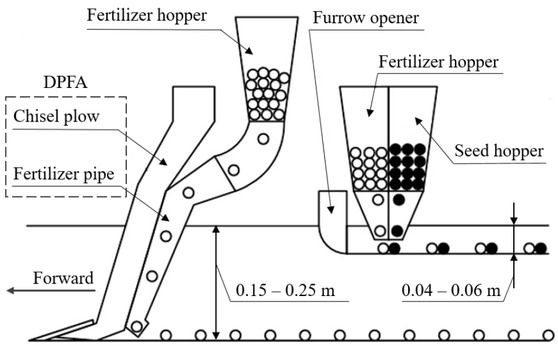
The mechanism of DPFA with simultaneous soybean sowing
The prototype is equipped with the DPFA which provides subsoil tillage and deep application of controlled-release (slow-release) fertilizers at depths of 0.15 – 0.25 m., with simultaneous wide-row sowing of soybeans and application of fertilizers (base fertilizer) at the same soybean sowing depth (0.04 – 0.06 m). Thus, this method of fertilizer application will allow plants to grow throughout the entire growing season by providing all-time essential nutrients. Figure 2 illustrates a schematic diagram of the prototype.
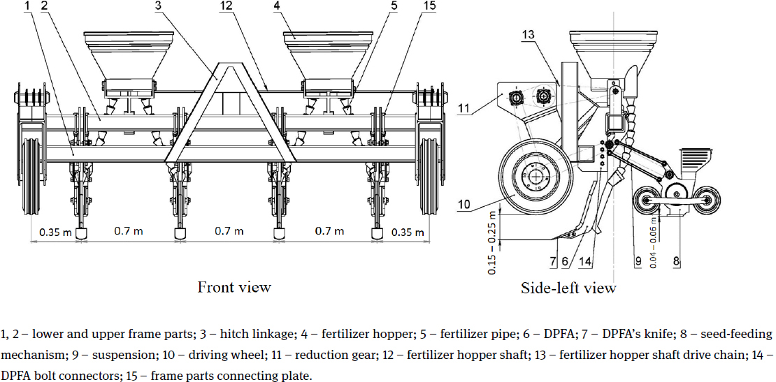
Schematic diagram of the prototype
Furthermore, this seeder prototype can be potentially used for other crops for example Maize (Zea mays L.). In addition, the prototype without seed-feeding mechanisms can be used for deep soil chiseling with fertilizer application before sowing crops by other agricultural types of machinery.Moreover, the DPFAitself could be adopted for any agricultural machinery.
2.2 Design of the DPFA
The design of the DPFA was based on a chisel plow model by Sandakov et al. [15], which was proposed for grain production in Russia. The model was designed and analyzed in a FEM simulation by static analysis with a total applied force of 5000 N. The chisel plow model has an optimum shape with four holes of a shank for a frame attachment. The knife of the chisel plow has a fixation to the shank by two bolts connection under a down part of the vertical plane of the chisel plow. Figure 3 shows the overall view of the chisel plow.
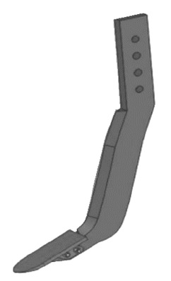
Chisel plow
The material properties of the chisel plow are specified in Table 1.
Material properties of the original chisel plow
| Chisel plow part | Shank | Knife |
|---|---|---|
| Properties, Unit | Steel | Steel |
| Density (kg/m3) | 7850 | 7820 |
| Young’s modulus (Pa) | 2.12 × 10¹¹ | 2.11 × 10¹¹ |
| Yield strength (Pa) | 3.45 × 10⁸ | 7.85 × 10⁸ |
| Tangent modulus (Pa) | 7.94 × 10¹⁰ | 7.94 × 10¹⁰ |
| Tensile yield stress (MPa) | 470 | 735 |
| Ultimate strength (MPa) | 660 | 981 |
| Poisson’s ratio | 0.31 | 0.29 |
| Mass (kg) | 10.75 | 1.29 |
Source: [15]
However, it was targeted to design a new DPFA plow, which would not only be satisfactory with technical issues for soybean cultivation, but meet the issues of conserving resources due to its streamline design.
2.3 Study Methods
The main study tasks were to design a new DPFA by improving the shape of the chisel plow. From selecting optimum material properties for its further manufacture, and developing a fertilizer pipe, which will be attached to the plow, and simultaneously perform deep tillage and deep placement fertilizer application. Furthermore, since the maximum subsoiling operating depth is expected to be 0.25 m, it was targeted to have a minimum safety factor (SF) between 2 and 2.5 for its material property. This minimum SF will not allow the DPFA to bend or break due to unpredictable working conditions in soil (e.g. mixed soil structure with different objects in the soil, a heavy soil property etc.). Moreover, this SF will promote an increasing effect to the DPFA’s service life.
In this study, the FEM allowed us to simulate the behavior of the DPFA under operating conditions by using a static analysis system called, AutoCAD Fusion 360, Autodesk, Inc. This simulation software shows the results of the analysis as a 3D televised model by generating specified areas with a different range of colors to visualize material behavior under different types of analysis [14].
The methods in this study have four main stages. First, the design of a 3D model with the needed overall dimensions and generated mesh are completed in the 3D simulation program. The second stage is the selection of material properties in the 3D simulation program with optimum yield and ultimate strength to control the optimum safety factor (SF). For ductile materials, the SF is expected to be checked for both yield and ultimate strengths. Since the yield strengths calculation will define the SF until the part starts to deform plasticity, however, the ultimate strengths result will define the SF until it reaches part failure. Therefore, in this study the SF will be assumed and calculated automatically in the 3D simulation program. This mechanical method is normalized and is used in the mechanical engineering industry to determine the elastic deflection for ductile materials [21, 22].
The third and final stage is the use of static analysis by exploiting a range of loads with different constraints (boundary condition) to the selected geometry, and the analysis of the results from the simulation so as to define material properties with an optimum SF for further manufacture. According to the study by Topakci et al. [14], the maximum draft force of each subsoil tine had 12.773 kN at the working depth of 0.45 – 0.75 m. In the study by Sandakov et al. [15], in the static analysis the total applied force of 5000 N was simulated on the chisel plow. In addition, the soil moisture content and soil compactness were important to consider since it will have a significant effect on the resistance forces in field experiments [23]. Unfortunately, there are no existing studies on draft force and soil resistance properties such as soil compactness and assumptions related to soil moisture in PK, Russia. Therefore, in this study for the static analysis of the DPFA was considered. A maximum force of 6000 N was applied for the depth of 0.25 m based on the result of Topakci et al. and Sandakov et al. [14, 15].Moreover, for the static simulation, the depths of 0.15 and 0.20 m were considered, and forces of 4500 and 5000 N were applied, respectively. As a result, based on the described method, objective’s function and optimization algorithm were developed and represented in Figure 4.
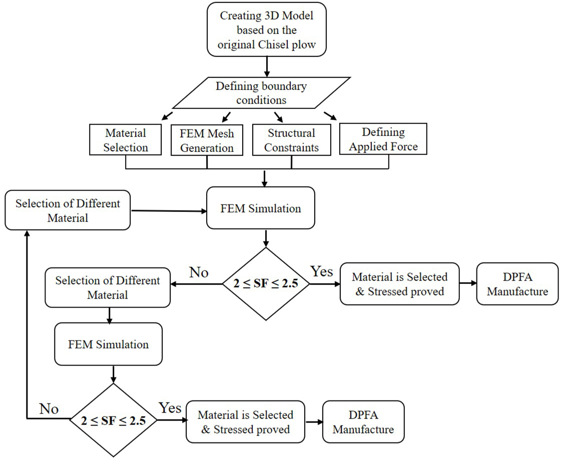
Flow chart of the DPFA design algorithm
This algorithm presents graphically the information introduced in the section of study methods as a block diagram, which can be used as one of the technical methods to optimize the DPFA.
3 Results and Discussion
3.1 Design of DPFA
At the first stage of the study, the DPFA was designed, to satisfy the technical requirements of the deep fertilizer application for soybean cultivation. The main issue was to perform deep tillage and simultaneously apply fertilizers into the soil at the depth of 0.15, 0.20 and 0.25 m. Second, the developed fertilizer pipe of fertilizer transportation should not increase the tractive resistance made by the chisel plow. Therefore, the total width of the fertilizer pipe was designed at 18 mm, which is less than the total thickness of the shank (24 mm). Moreover, the fertilizer pipe has a round inlet and square outlet, and from the top to the bottom of the fertilizer pipe, the pipe has a truncated shape reduced by 10 mm. Figure 5 shows a schematic diagram of the designed DPFA with overall dimensions, (mm). In addition, Figure 6 illustrates a schematic diagram of the designed fertilizer pipe with sections views in order to reveal the inside shape.
Moreover, the DPFA was designed with five fixation holes to adjust to the three depths for the seeder prototype. Thus, it was convenient to simulate accurately the different applicable depths by different boundary conditions.
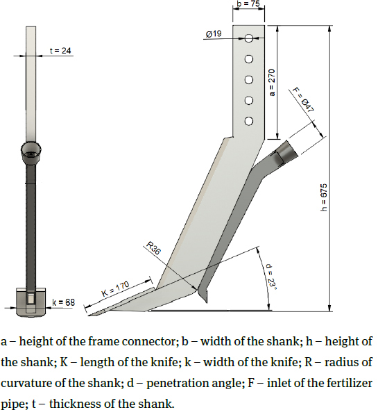
Schematic diagram of the DPFA
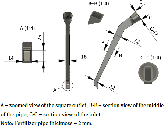
Schematic diagram of the fertilizer pipe
Furthermore, the knife fixation to the shank and the fixation of the fertilizer pipe to the shank were not conducted in this study since this is the first DPFA prototype. These fixations were simulated as if it was fixed by an arc welding and had a full body connection. However, the different material properties of the knife, chisel shank and fertilizer pipe were considered.
3.2 FEM Simulation
Once the design was completed, a finite element model of the DPFA for soybean cultivation was done. The mesh sensitivity analysiswas conducted to acquire the optimum mesh size and achieve the proper accuracy of computations. However, in the study by Kamal et al. [24], was discussed that the stress values did not change by an appreciable amount by decreasing the mesh size, however, there was an exponential increase in the nodes and elements number, that has resulted in a rise of the processing time and data storage requirements without much significance in the accuracy of the stress results. Thus, the mesh of the DPFA model was meshed and calculated automatically by the Fusion 360 software based on Model-Based Size (Average Element Size) 1–10%. Additionally, all edges of the DPFA model were filleted (rounded) by the radius of 2 mm to reduce the stress concentrations. The numerical model is shown in Figure 7, consists of 116,134 nodes and 66,221 elements. In Table 2 is summarized the result of the used mesh.
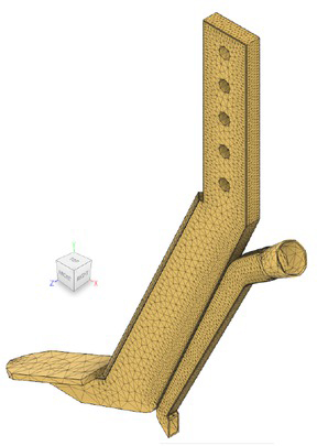
Finite element model and meshing construction of the DPFA
Mesh characteristics
| Base Mesh (Solids): 116,134 nodes, 66,221 elements |
| Average Element Size (% of model size): |
| Scale Mesh Size per part: 10 |
| Max. Adjacent Mesh Size Ratio: 1.5 |
| Max. Aspect Ratio: 10 |
| Max. Turn Angle on Curves (Deg.): 60 |
| Min. Element Size (% of average size): 20 |
| Element order: Parabolic |
| Number of Tetrahedra: 66,386 (100% of elements (100% of volume)): |
| Face Angle: min - 0.652, max - 177 |
| Dihedral Angle: min - 0.724, max - 178 |
| Worst Shape Ratio: 202 on element 11,976 |
| Worst Aspect Ratio: 25.7 on element 8,107, shortest |
| edge: 0.000144, longest: 0.048 |
| Lowest Collapse Ratio: 0.00799 on element 11,976 |
| Worst Jacobian Ratio: 1 on element 1 |
As the maximum load will be evenly distributed throughout the subsoil area of the DPFA, however, in the boundary condition of the simulation, the different load was applied on the maximum load surface of the knife. The principal of the boundary condition is shown in Figure 8. The boundary conditions of the static simulation are given in Figure 9.
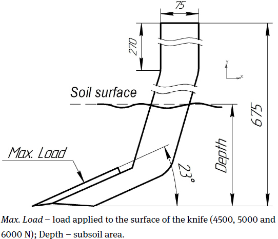
The overall view of boundary conditions
The next steps were the selection of the material properties to achieve the defined SF through multiple experiments within the simulation in accordance with the DPFA design algorithm (Fig. 4). Thus, as the maximum subsoiling operating depth of the DPFA is 0.25 m with the greatest static force of 6000 N (which requires the optimum safety factor of 2≤ SF≤ 2.5), making the result of the static analysis for this case was presented graphically. The end results of the simulation with the final selected material property and various behaviors of the materials are shown in figure 10.
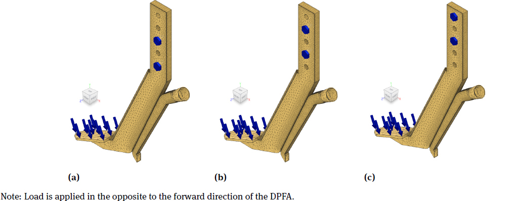
Boundary conditions
a) – Depth – 0.15 m, load – 4500 N; b) – Depth – 0.20 m, load – 5000 N; c) – Depth – 0.25 m, load – 6000 N; the diameter of bolts connector is 19 mm.
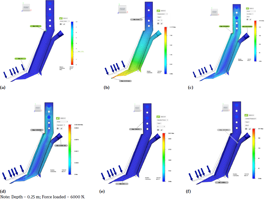
Results of the static analysis of the DPFA
a) – Safety factor; b) – Displacement; c) – Stress; d) – Strain Equivalent; e) – Reaction Force; f) – Contact Pressure.
According to the static simulation results (Figure 10, (a)), the minimum SF is 2.3 per body under loaded force of 6000 N. The SF is a ratio of the maximum strength of the selected material to the stress calculated in the simulation, and shows the calculation result based on the yield strength. Thus, this SF target meets the set optimum SF (2≤ SF≤ 2.5), and the DPFA design is not expected to bend or break with the current force load and analysis criteria. In addition, the simulation shows the minimum SF of 3.1 for the depth of 0.15 m and a force load of 4500 N, as well as 2.8 for 0.20 m with 5000 N respectively. Table 3 summarizes the optimum material properties for the DPFA used in the static stimulation.
Material properties used in the simulation
| DPFA part | Shank | Fertilizer pipe |
|---|---|---|
| Properties, Unit | Steel AISI 4135 QT | Steel |
| Density (kg/m3) | 7860 | 7850 |
| Young’s modulus (GPa) | 207 | 205 |
| Yield strength (MPa) | 780 | 207 |
| Ultimate Tensile Strength (MPa) | 950 | 345 |
| Modulus of Elasticity (GPa) | 205 | 185 |
| Bulk Modulus (GPa) | 160 | 160 |
| Shear Modulus (GPa) | 80 | 75 |
| Poisson’s Ratio | 0.33 | 0.29 |
| Mass (kg) | 11.2 | 0.58 |
According to Table 3, one of the suitable materials for the chisel shank, as part of the main DPFA body, was chosen to achieve the set SF is the AISI 4135 QT steel. However, this is the general recommendation based on the simulation conditions. And the further selected material for the manufacture of the DPFA may not be appropriate to a particular industry or application due to specific working conditions or other factors relevant to cultural expectations by way of farming. Therefore, different types of material properties were used for the static stimulation where the yield strength was varied from 350 to 900 MPa, and the ultimate strength was varied from 420 to 1000 MPa. Thus, it was determined that for this shape of the DPFA to achieve the minimum SF from 2 to 2.5, the main material properties of carbon steel should possess a high yield strength of 800 MPa and ultimate strength of not less than 900 MPa, using Young’s Modulus of 207×10−3 MPa with Poisson’s Ratio of 0.33. Moreover, it is always necessary to consider all physical and mechanical properties in order to control a wear-resistance property depending on working conditions [25, 26].
Referring to Table 1 of the material properties of the original chisel plow the yield strength and ultimate strength are much less than it was obtained in the simulation. This result occurred because it used a greater applied force than in the previous study. However, the total mass was reduced by 0.26 kg due to the fact that the overall design of the original chisel plow was changed.
The static simulation for 6000 N shows that the DPFA model had maximum stress of 379.9 MPa (Figure 10, (c)), the equivalent maximum strain of 25.6×10⁻⁴ mm/mm (Figure 10, (d)), the maximum displacement of 3.1 mm (Figure 10, (b)), the total reaction force of 5642 N (Figure 10 (e)), and the total contact pressure of 207 MPa (Figure 10, (f)). In Table 4 is a detailed results summary of the simulation for 0.25 m depth with 6000 N loaded force.
Full result summary of 0.25 m by 6000 N loaded force
| Category | Minimum | Maximum |
|---|---|---|
| Safety Factor (Per Body) | 2.374 | 15 |
| Stress Von Mises (MPa) | 0.00124 | 379.9 |
| 1st Principal | −98.81 | 488.7 |
| 3rd Principal | −382.3 | 141.1 |
| Normal XX | −177.7 | 278 |
| Normal YY | −323.1 | 384.1 |
| Normal ZZ | −115.3 | 141.4 |
| Shear XY | −121.8 | 157.2 |
| Shear YZ | −66.26 | 66.09 |
| Shear ZX | −104.7 | 104.2 |
| Displacement total (mm) | 0 | 3.121 |
| X | −0.007205 | 2.216 |
| Y | −2.198 | 0.5473 |
| Z | −0.004175 | 0.003852 |
| Reaction Force total (N) | 0 | 5642 |
| X | −4258 | 1688 |
| Y | −4027 | 4939 |
| Z | −217.9 | 196.6 |
| Strain Equivalent | 9.958E−09 | 0.002568 |
| (mm/mm) | ||
| 1st Principal | −2.863E−07 | 0.002872 |
| 3rd Principal | −0.002122 | 5.263E−06 |
| Normal XX | −6.224E−04 | 0.00105 |
| Normal YY | −0.001094 | 0.001607 |
| Normal ZZ | −6.352E−04 | 2.532E−04 |
| Shear XY | −0.001565 | 0.002021 |
| Shear YZ | −8.514E−04 | 8.493E−04 |
| Shear ZX | −0.001346 | 0.001339 |
| Contact Pressure total | 0 | 207 |
| (MPa) | ||
| X | −80.16 | 134.1 |
| Y | −145.9 | 86.01 |
| Z | −59.98 | 59.65 |
The static simulation for 4500 and 5000 N had the maximum stress of 285.4 and 316.8 MPa, the maximum equivalent strain of 19.3×10⁻⁴ and 21.4×10⁻⁴ mm/mm, the maximum displacement of 1.5 and 2.1 mm, the total reaction force of 3243 and 3930 N, and the total contact pressure of 153.3 and 172.5 MPa, respectively. A brief results summary is specified in Tables 5 and 6.
Result summary of 0.15 m by 4500 N loaded force
| Category | Minimum | Maximum |
|---|---|---|
| Safety Factor (Per Body) | 3.16 | 15 |
| Stress Von Mises (MPa) | 6.309E−07 | 285.4 |
| Displacement total (mm) | 0 | 1.571 |
| Reaction Force total (N) | 0 | 3243 |
| Strain Equivalent | 3.96E−12 | 0.00193 |
| (mm/mm) | ||
| Contact Pressure total | 0 | 153.3 |
| (MPa) |
Result summary of 0.20 m by 5000 N loaded force
| Category | Minimum | Maximum |
|---|---|---|
| Safety Factor (Per Body) | 2.84 | 15 |
| Stress Von Mises (MPa) | 9.922E−05 | 316.8 |
| Displacement total (mm) | 0 | 2.152 |
| Reaction Force total (N) | 0 | 3930 |
| Strain Equivalent | 4.819E−10 | 0.00214 |
| (mm/mm) | ||
| Contact Pressure total | 0 | 172.5 |
| (MPa) |
Furthermore, the stress and strain analysis of the static simulation showed the most stressed areas where there are stress concentrations on the DPFA and areas of expected breaks. These two criteria are important to improve the future design of machinery parts and practical experiments [27, 28]. For instance, the stress analysis shows the areas where strain gages can be attached for practical experiments to obtain soil resistance force and strain-induced on the DPFA.
3.3 Further research steps
As the second step of the study, based on the simulation results and the selected material properties, a DPFA prototype was manufactured and assembled with the seeder prototype for further field experiments. Figure 11 illustrates the manufactured DPFA and developed seeder prototype at Primorskaya State Academy of Agriculture, Russia.
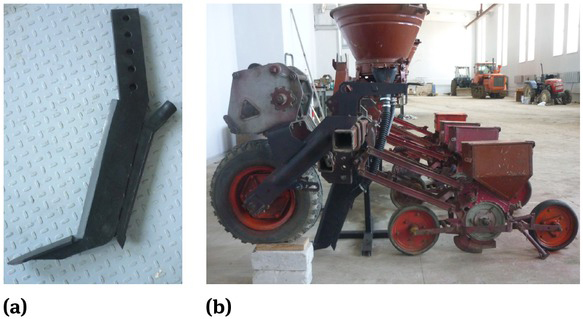
DPFA and Seeder prototype, 2019
a) – Manufactured DPFA; b) – Developed seeder prototype
Further field experiments with additional equipment (e.g. Universal data logger recorder with strain gages) are necessary to verify the applied simulation force and selected material property. Moreover, it is necessary to improve practically the final shape of the DPFA before its produced in significant quantities. Furthermore, the field experiments can also verify the developed fertilizer pipe in the point of fertilizer transportation, and soil sticking to the outlet of the fertilizer pipe. In addition, soil resistance properties such as soil compactness and assumptions related to soil moisture should be considered in field experiments.
4 Conclusions
This study was focused on the new design of the DPFA, optimum material selection and obtaining the required safety factor of the DPFA for soybean cultivation. A new fertilizer pipe was developed to transport fertilizer into the soil, which is not increasing the tractive resistance. However, practical field experiments are needed to verify the practical application of the DPFA.
The FEM was used as the main technique for the static simulation of the DPFA to select the optimum material properties and improve the safety factor. Three different applied forces in the static simulation (4500, 5000 and 6000 N) were considered as for three different application depths of fertilizers (0.15, 0.20, and 0.25 m). According to the study, the simulation results can be summarized as follows:
The best selected material property for the DPFA was the AISI 4135 QT carbon steel plating with high yield strength of 780 MPa and ultimate tensile strength of 950MPa, Young’s Modulus of 207 GPa and with Poisson’s Ratio of 0.33.
The maximum applied force of 6000 N shows that the DPFA model had the maximum stress of 379.9 MPa and strain of 25.6×10⁻⁴ mm/mm, the total reaction force of 5642 N, contact pressure of 207 MPa, and the maximum displacement of 3.1 mm.
The applied force of 4500 and 5000 N had the maximum stress of 285.4 and 316.8MPa, maximum strain of 19.3×10⁻⁴ and 21.4×10⁻⁴ mm/mm, the maximum displacement of 1.5 and 2.1 mm, total reaction force of 3243 and 3930 N, and total contact pressure of 153.3 and 172.5 MPa, respectively.
The total mass of the DPFA was 11.78 kg.
Based on the simulation result, a DPFA prototype was manufactured and assembled with the seeder prototype for further field experiments.
Acknowledgement
This study was conducted by Pilot Project for Strategical International Collaborative Research in the Field of Agriculture between Japan and Russian Federation under the auspices of Ministry of Agriculture, Forestry and Fisheries, Japan. A special thanks to our Editor/Proof Reader Mr. Eli Joel Pappas, Linguistician and English Teacher.
References
[1] Fujii T, Hasegawa H, Ohyama T, Sinegovskaya VT. Evaluation of tillage efficiency and power requirements for a deep-placement fertilizer applicator with reverse rotational rotary. Rus Agr Sci. 2015 Nov 1;41(6):498-503.10.3103/S1068367415060233Search in Google Scholar
[2] Patuk I, Hasegawa H, Borowski PF, Borodin I, Lyude A. Modification of Seeder SZ-3, 6 by using Deep Placement Fertilizer Application Technology. In: Proc. Book of 9th Int. Symp. on Machinery and Mechatronics for Agr. and Bio. Eng. (ISMAB2018). (28-30 May 2018, Jeju, Korea) Jeju, 2018, pp.801-806.Search in Google Scholar
[3] Wang Yx, Chen Sp, Zhang Dx, Li Ya, Tao Cu, Jing Hr, Li Yh. Effects of subsoiling depth, period interval and combined tillage practice on soil properties and yield in the Huang-Huai-Hai Plain, China. J Int Agr. 2020 Jun 1;19(6):1596-608.10.1016/S2095-3119(19)62681-XSearch in Google Scholar
[4] Takahashi Y, Chinushi T, Nagumo Y, Nakano T, Ohyama T. Effect of deep placement of controlled release nitrogen fertilizer (coated urea) on growth, yield, and nitrogen fixation of soybean plants. Soil Sci Plant Nutr. 1991 Jun 1;37(2):223-31.10.1080/00380768.1991.10415032Search in Google Scholar
[5] Tewari K, Onoda M, Sato N, Ito S, Yamazaki A, Fujikake H, Ohtake N, Sueyoshi K, Takehashi Y, Ohyama T. Comparison of the effects of application of deep placement of slow release N (lime nitrogen and coated urea), P and K fertilizers on yield and quality of soybean (Glycine max (L.) Merr.) seed. Bull Facul Agric. Niigata Univ. 2005 Aug;58(1):45-53.Search in Google Scholar
[6] Kaushal T, Onda M, Ito S, Yamazaki A, Fujikake H, Ohtake N, Sueyoshi K, Takahashi Y, Ohyama T. Effect of Deep Placement of Slow-release Fertilizer (Lime Nitrogen) Applied at Different Rates on Growth, N2 Fixation and Yield of Soya Bean (Glycine max [L.] Merr.). J Agron Crop Sci. 2006 Dec;192(6):417-26.10.1111/j.1439-037X.2006.00230.xSearch in Google Scholar
[7] Ohyama T, Takahashi Y, Nagumo Y, Tanaka K, Sueyoshi K, Ohtake N, Ishikawa S, Kamiyama S, Saito M, Tewari K. Deep placement of lime nitrogen promotes nitrogen fixation and seed yield of soybean with eflcient utilization rates. In: Proc. 19th World Congress of Soil Science for a Changing World 2010. (1-6 Aug 2010, Brisbane, Australia) Brisbane, 2010, pp. 32-35.Search in Google Scholar
[8] Liu TQ, Fan DJ, Zhang XX, Chen J, Li CF, Cao CG. Deep placement of nitrogen fertilizers reduces ammonia volatilization and increases nitrogen utilization efficiency in no-tillage paddy fields in central China. Field Crops Res. 2015 Dec 1;184:80-90.10.1016/j.fcr.2015.09.011Search in Google Scholar
[9] Gaihre YK, Singh U, Biswas C, DeWald J. Nitrogen use efficiency, crop productivity and environmental impacts of urea deep placement in lowland rice fields. In: Proc. Int. Conf. on Nitrogen Initiative Conference „Solutions to improve nitrogen use efficiency for the world“ (Dec 2016 Melbourne, Australia) Melbourne, 2016, pp. 4-8.Search in Google Scholar
[10] Mazid Miah M, Gaihre YK, Hunter G, Singh U, Hossain SA. Fertilizer deep placement increases rice production: evidence from farmers’ fields in southern Bangladesh. Agron J. 2016;108(2):805-12.10.2134/agronj2015.0170Search in Google Scholar
[11] Zeng Z, Chen Y, Zhang X. Modelling the interaction of a deep tillage tool with heterogeneous soil. Comput Electron Agric. 2017 Dec 1;143:130-8.10.1016/j.compag.2017.10.005Search in Google Scholar
[12] Hang C, Gao X, Yuan M, Huang Y, Zhu R. Discrete element simulations and experiments of soil disturbance as affected by the tine spacing of subsoiler. Bios Eng. 2018 Apr 1; 168:73-82.10.1016/j.biosystemseng.2017.03.008Search in Google Scholar
[13] Ebrahimi R, Mirdamadi HR, Ziaei-Rad S. Operational modal analysis and fatigue life estimation of a chisel plow arm under soil-induced random excitations. Measurement. 2018 Feb 1; 116:451-7.10.1016/j.measurement.2017.11.020Search in Google Scholar
[14] Topakci M, Celik HK, Canakci M, Rennie AE, Akinci I, Karayel D. Deep tillage tool optimization by means of finite element method: Case study for a subsoiler tine. J Food Agric Environ. 2010 Apr 1;8(2):531-6.Search in Google Scholar
[15] Sandakov T, Sandakova N, Chang L, Hasegawa H, Radnaev D. Optimum design of a chisel plow for grain production in the Republic of Buryatia, Russian Federation. AMA-Agr Mech Asia Af. 2019;50(1):73-8.Search in Google Scholar
[16] Hoque MA, Wohab MA, Hossain MA, Saha KK, Hassan MS. Improvement and evaluation of Bari USG applicator. Agricultural Engineering International: CIGR J. 2013 Jul 1;15(2):87-94.Search in Google Scholar
[17] Ahamed MS, Ziauddin AT, Sarker RI. Design of improved urea super granule applicator. Int J App Sci Eng Res. 2014;3(1):98-104.Search in Google Scholar
[18] Wang Y, Li N, Ma Y, Tong J, Pfleging W, Sun J. Field experiments evaluating a biomimetic shark-inspired (BioS) subsoiler for tillage resistance reduction. Soil Tillage Res. 2020 Feb 1;196:104432.10.1016/j.still.2019.104432Search in Google Scholar
[19] Malón H, Aguirre AJ, Boné A, Vidal M, García-Ramos FJ. Design and testing of an agricultural implement for underground application of rodenticide bait. Sensors. 2015 Jan;15(1):2006-20.10.3390/s150102006Search in Google Scholar PubMed PubMed Central
[20] Zienkiewicz OC, Taylor RL, Zhu JZ. The finite element method: its basis and fundamentals. Elsevier; 2005 May 26.Search in Google Scholar
[21] Radovic M, Lara-Curzio E, Riester L. Comparison of different experimental techniques for determination of elastic properties of solids. Mat Sci Eng A-Struct. 2004 Mar 15;368(1-2):56-70.10.1016/j.msea.2003.09.080Search in Google Scholar
[22] Miljojković J, Bijelić I, Vranić N, Radovanović N, Živković M. Determining elastic modulus of the material by measuring the deflection of the beam loaded in bending. Tehnički vjesnik. 2017 Jul 31;24(4):1227-34.10.17559/TV-20170609133537Search in Google Scholar
[23] Lisowski A, Klonowski J, Green O, Świętochowski A, Sypuła M, Strużyk A, Nowakowski T, Chlebowski J, Kamiński J, Kostyra K, Mieszkalski L. Duckfoot tools connected with flexible and stiff tines: Three components of resistances and soil disturbance. Soil Tillage Res. 2016 May 1;158:76-90.10.1016/j.still.2015.12.003Search in Google Scholar
[24] Kamal M, Rahman MM, Sani MS. Fatigue life prediction using simplified endurance function model. Adv Mech Eng. 2013;5:581754.10.1155/2013/581754Search in Google Scholar
[25] Sasaki T,Watanabe K, Nohara K, Ono Y, Kondo N, Sato S. Physical and mechanical properties of high manganese non-magnetic steel and its application to various products for commercial use. Trans Iron Steel Ins Japan. 1982;22(12):1010-20.10.2355/isijinternational1966.22.1010Search in Google Scholar
[26] Tavio, Anggraini R, Raka IG, Agustiar. Tensile strength/yield strength (TS/YS) ratios of high-strength steel (HSS) reinforcing bars. In: AIP Conference Proceedings 2018 May 15 (Vol. 1964, No. 1, p. 020036). AIP Publishing LLC.10.1063/1.5038318Search in Google Scholar
[27] Celik HK, Akinci I. Analytical and Finite Element Method Based Stress Analysis of Rotary Elements: Case Study for the Motion Transmission Gears of a Rotary Drum Mower. J Failure Anal Prev. 2016 Apr 1;16(2):293-301.10.1007/s11668-016-0084-3Search in Google Scholar
[28] Celik HK, Cinar R, Kunt G, Rennie AE, Ucar M, Akinci I. Finite Element Analysis of a PTO Shaft Used in an Agricultural Tractor. Ergon Int J. 2018 May 15;2(3).10.23880/EOIJ-16000147Search in Google Scholar
© 2020 I. Patuk et al., published by De Gruyter
This work is licensed under the Creative Commons Attribution 4.0 International License.
Articles in the same Issue
- Regular Articles
- Fabrication of aluminium covetic casts under different voltages and amperages of direct current
- Inhibition effect of the synergistic properties of 4-methyl-norvalin and 2-methoxy-4-formylphenol on the electrochemical deterioration of P4 low carbon mold steel
- Logistic regression in modeling and assessment of transport services
- Design and development of ultra-light front and rear axle of experimental vehicle
- Enhancement of cured cement using environmental waste: particleboards incorporating nano slag
- Evaluating ERP System Merging Success In Chemical Companies: System Quality, Information Quality, And Service Quality
- Accuracy of boundary layer treatments at different Reynolds scales
- Evaluation of stabiliser material using a waste additive mixture
- Optimisation of stress distribution in a highly loaded radial-axial gas microturbine using FEM
- Analysis of modern approaches for the prediction of electric energy consumption
- Surface Hardening of Aluminium Alloy with Addition of Zinc Particles by Friction Stir Processing
- Development and refinement of the Variational Method based on Polynomial Solutions of Schrödinger Equation
- Comparison of two methods for determining Q95 reference flow in the mouth of the surface catchment basin of the Meia Ponte river, state of Goiás, Brazil
- Applying Intelligent Portfolio Management to the Evaluation of Stalled Construction Projects
- Disjoint Sum of Products by Orthogonalizing Difference-Building ⴱ
- The Development of Information System with Strategic Planning for Integrated System in the Indonesian Pharmaceutical Company
- Simulation for Design and Material Selection of a Deep Placement Fertilizer Applicator for Soybean Cultivation
- Modeling transportation routes of the pick-up system using location problem: a case study
- Pinless friction stir spot welding of aluminium alloy with copper interlayer
- Roof Geometry in Building Design
- Review Articles
- Silicon-Germanium Dioxide and Aluminum Indium Gallium Arsenide-Based Acoustic Optic Modulators
- RZ Line Coding Scheme With Direct Laser Modulation for Upgrading Optical Transmission Systems
- LOGI Conference 2019
- Autonomous vans - the planning process of transport tasks
- Drivers ’reaction time research in the conditions in the real traffic
- Design and evaluation of a new intersection model to minimize congestions using VISSIM software
- Mathematical approaches for improving the efficiency of railway transport
- An experimental analysis of the driver’s attention during train driving
- Risks associated with Logistics 4.0 and their minimization using Blockchain
- Service quality of the urban public transport companies and sustainable city logistics
- Charging electric cars as a way to increase the use of energy produced from RES
- The impact of the truck loads on the braking efficiency assessment
- Application of virtual and augmented reality in automotive
- Dispatching policy evaluation for transport of ready mixed concrete
- Use of mathematical models and computer software for analysis of traffic noise
- New developments on EDR (Event Data Recorder) for automated vehicles
- General Application of Multiple Criteria Decision Making Methods for Finding the Optimal Solution in City Logistics
- The influence of the cargo weight and its position on the braking characteristics of light commercial vehicles
- Modeling the Delivery Routes Carried out by Automated Guided Vehicles when Using the Specific Mathematical Optimization Method
- Modelling of the system “driver - automation - autonomous vehicle - road”
- Limitations of the effectiveness of Weigh in Motion systems
- Long-term urban traffic monitoring based on wireless multi-sensor network
- The issue of addressing the lack of parking spaces for road freight transport in cities - a case study
- Simulation of the Use of the Material Handling Equipment in the Operation Process
- The use of simulation modelling for determining the capacity of railway lines in the Czech conditions
- Proposals for Using the NFC Technology in Regional Passenger Transport in the Slovak Republic
- Optimisation of Transport Capacity of a Railway Siding Through Construction-Reconstruction Measures
- Proposal of Methodology to Calculate Necessary Number of Autonomous Trucks for Trolleys and Efficiency Evaluation
- Special Issue: Automation in Finland
- 5G Based Machine Remote Operation Development Utilizing Digital Twin
- On-line moisture content estimation of saw dust via machine vision
- Data analysis of a paste thickener
- Programming and control for skill-based robots
- Using Digital Twin Technology in Engineering Education – Course Concept to Explore Benefits and Barriers
- Intelligent methods for root cause analysis behind the center line deviation of the steel strip
- Engaging Building Automation Data Visualisation Using Building Information Modelling and Progressive Web Application
- Real-time measurement system for determining metal concentrations in water-intensive processes
- A tool for finding inclusion clusters in steel SEM specimens
- An overview of current safety requirements for autonomous machines – review of standards
- Expertise and Uncertainty Processing with Nonlinear Scaling and Fuzzy Systems for Automation
- Towards online adaptation of digital twins
- Special Issue: ICE-SEAM 2019
- Fatigue Strength Analysis of S34MnV Steel by Accelerated Staircase Test
- The Effect of Discharge Current and Pulse-On Time on Biocompatible Zr-based BMG Sinking-EDM
- Dynamic characteristic of partially debonded sandwich of ferry ro-ro’s car deck: a numerical modeling
- Vibration-based damage identification for ship sandwich plate using finite element method
- Investigation of post-weld heat treatment (T6) and welding orientation on the strength of TIG-welded AL6061
- The effect of nozzle hole diameter of 3D printing on porosity and tensile strength parts using polylactic acid material
- Investigation of Meshing Strategy on Mechanical Behaviour of Hip Stem Implant Design Using FEA
- The effect of multi-stage modification on the performance of Savonius water turbines under the horizontal axis condition
- Special Issue: Recent Advances in Civil Engineering
- The effects of various parameters on the strengths of adhesives layer in a lightweight floor system
- Analysis of reliability of compressed masonry structures
- Estimation of Sport Facilities by Means of Technical-Economic Indicator
- Integral bridge and culvert design, Designer’s experience
- A FEM analysis of the settlement of a tall building situated on loess subsoil
- Behaviour of steel sheeting connections with self-drilling screws under variable loading
- Resistance of plug & play N type RHS truss connections
- Comparison of strength and stiffness parameters of purlins with different cross-sections of profiles
- Bearing capacity of floating geosynthetic encased columns (GEC) determined on the basis of CPTU penetration tests
- The effect of the stress distribution of anchorage and stress in the textured layer on the durability of new anchorages
- Analysis of tender procedure phases parameters for railroad construction works
- Special Issue: Terotechnology 2019
- The Use of Statistical Functions for the Selection of Laser Texturing Parameters
- Properties of Laser Additive Deposited Metallic Powder of Inconel 625
- Numerical Simulation of Laser Welding Dissimilar Low Carbon and Austenitic Steel Joint
- Assessment of Mechanical and Tribological Properties of Diamond-Like Carbon Coatings on the Ti13Nb13Zr Alloy
- Characteristics of selected measures of stress triaxiality near the crack tip for 145Cr6 steel - 3D issues for stationary cracks
- Assessment of technical risk in maintenance and improvement of a manufacturing process
- Experimental studies on the possibility of using a pulsed laser for spot welding of thin metallic foils
- Angular position control system of pneumatic artificial muscles
- The properties of lubricated friction pairs with diamond-like carbon coatings
- Effect of laser beam trajectory on pocket geometry in laser micromachining
- Special Issue: Annual Engineering and Vocational Education Conference
- The Employability Skills Needed To Face the Demands of Work in the Future: Systematic Literature Reviews
- Enhancing Higher-Order Thinking Skills in Vocational Education through Scaffolding-Problem Based Learning
- Technology-Integrated Project-Based Learning for Pre-Service Teacher Education: A Systematic Literature Review
- A Study on Water Absorption and Mechanical Properties in Epoxy-Bamboo Laminate Composite with Varying Immersion Temperatures
- Enhancing Students’ Ability in Learning Process of Programming Language using Adaptive Learning Systems: A Literature Review
- Topical Issue on Mathematical Modelling in Applied Sciences, III
- An innovative learning approach for solar power forecasting using genetic algorithm and artificial neural network
- Hands-on Learning In STEM: Revisiting Educational Robotics as a Learning Style Precursor