Estimating of cutting force and surface roughness in turning of GFRP composites with different orientation angles using artificial neural network
-
Ahmet Yardimeden


Abstract
Glass fiber-reinforced polymer (GFRP) composite materials are widely used in many manufacturing industries due to their low density and high strength properties, and consequently, the need for precision machining of such composites has significantly increased. Since composite materials have an anisotropic and heterogeneous structure, the machinability of composite materials is quite different from conventional materials. In the machining of GFRP composite pipes, tool wear, cracks or delamination, a rough surface, etc., many unwanted problems may occur. Therefore, GFRP composite pipes are difficult to process. To prevent such problems, it is very crucial to select suitable process parameters, thereby achieving the maximum performance for the desired dimensional integrity. In this study, through turning of GFRP composites with different orientation angles (30°, 60°, and 90°), the effects of cutting speed (50, 100, and 150 m·min−1), feed rate (0.1, 0.2, and 03 mm·rev−1), and depth of cut (1, 2, and 3 mm) on cutting force and surface roughness were determined. Then, with the use of these machining parameters, a model of the system for determining cutting force and surface roughness was established with artificial neural networks (ANNs). The ANN was trained using Levenberg–Marquardt backpropagation algorithm. It has been observed that the results obtained with the ANN model are very close to the data found in experimental studies. In both experimental and model-based analysis, minimum cutting force (44 N) and surface roughness (2.22 µm) were achieved at low fiber orientation angle (30°), low feed rate (0.1 mm·rev−1), and depth of cut (1 mm) at high cutting speeds (150 m·min−1).
1 Introduction
In this modern time, most of multi parameter processes can be modeled via artificial neural networks (ANNs) by which almost real-time monitoring of variety of experimental process becomes possible. With such models, besides the real-time monitoring, one can estimate the optimum input parameters for the desired outcome of experiments without conducting the physical time consuming and costly experiments. Similar to the ANN models developed for applied science found in the literature, identifying optimum input parameters for a desirable output in machining and turning processes is also possible with appropriate ANN models. In particular, it is thought that such models are important in estimating the optimum parameters needed in glass fiber-reinforced polymer (GFRP) processing systems. GFRP materials are the ones introduced and used in variety of high-tech areas in this contemporary time.
Naturally, the matter utilized in high-tech areas, such as defense, aviation, space, maritime, bioengineering and transportation industry, and electrical and electronics [1,2,3], need to possess exclusive properties, such as low density, rigidity, high strength, fatigue resistance, abrasion and impact resistant and resistant to corrosion [4,5]. In some applications, often combination of these properties (which is highly difficult) may be desired. Composite materials are structured by combining at least two of different materials at a macro level (insoluble in each other). Fiber-reinforced layered composites are of these materials structured with fiber layers that could differ in type and orientation. The arrangement of the fibers in the matrix enables the composite material to show an anisotropic and somehow inhomogeneous structure, which is important factor affecting the mechanical properties and machinability of composite materials [1,4,5,6]. Such structural properties beget significant differences between machining of composite materials and of conventional metals, where plastic deformation dominates the material removal process.
The composite materials, such as fiber-reinforced polymer (FRP) and GFRP composites, have a much more complex structure (mainly near to the net shape to ensure geometric tolerance, needed for surface quality), which requires a different chip removal mechanism [7]. To achieve a qualitative cutting performance in machining of GFRP composites, it is necessary to select appropriate cutting parameters in regard to this complex metal removal mechanism [8,9]. The appropriate cutting parameters provide significant saving in both financial and time costs and consequently increase in process efficiency [10].
Besides the production method [11,12,13,14,15], tool material [7,16,17], tool geometry [18,19,20,21], machining parameters [22,23,24,25], and fiber orientation [18,26,27,28,29] are important in machining of GFRP composites. With both experimental and mathematical models, it has been made clear that chip formation and defects are highly correlated with fiber orientation in the machining of FRP and GFRP composites [30]. Kini and Chincholkar [22] experimentally investigated the effects of machining parameters on surface roughness and material removal rate in ±30° filament wound GFRP processing using a coated tungsten carbide cutting tool. The obtained results showed that surface roughness is primarily influenced by the feed rate and depth of cut. Therefore, to achieve a better surface quality, it is important to analyze various machining conditions to select the ones best suited to process optimization [31]. Palanikumar [32] showed that mathematical models (they developed) can be effectively used to estimate surface roughness in turning GFRP workpieces based on machining parameters (fiber orientation, cutting speed, feed rate, depth of cut). He concluded that the surface roughness decreased as the cutting speed and depth of cut increased and the surface roughness increased as the fiber orientation angle and feed rate increased. Khashaba et al. developed regression models by which multivariate regression analysis was conducted and correlations between processing parameters and the responses were investigated in drilling of GFRP [33,34]. They found that the thrust force was the most effective factor in drilling GFRP, and the laminate thickness was highly effective in the measured temperature. Neeli et al. used gray relational analysis (GRA) and desirability function analysis to optimize machining parameters, such as fiber orientation angle, helix angle, spindle speed, and feed rate for milling GFRP composites [35]. They showed that fiber orientation angle is the most important parameter for GFRP composites before helix angle, feed rate, and spindle speed.
To enable a wide-range surface roughness analysis in machining, particular mathematical models have been developed and analysis of variance (ANOVA) was performed with 95% confidence level to validate these models with respect to experimental studies [36]. Ekici and Motorcu investigated the effects of drilling parameters and tool coating conditions on the processing of CFRP composites and optimized with the help of Taguchi-based GRA. ANOVA showed a high correlation coefficients between R a, D f, and UCFF, and also drilling parameters as well as hole characteristics [37]. They used ANOVA to determine the effects of control factors on the hole damage, which occurs in the form of delamination of the cutting tool geometry in drilling GLARE. They concluded that feed rate and cutting speed were more effective than cutting tool geometry on delamination formation [38]. It was also reported that there was very little wear in the cutting tools used in their study under different drilling conditions [6].
To develop robust and wide-range parameter optimization machining methods, recently, ANN-based models have been introduced to virtually process FRP composites [39] and are reported as more precise in forecasting system’s outcome. In general, Levenberg–Marquardt (LM) backpropagation learning algorithm is used in the learning phase of the ANN model. In the processes like FRP machining, some input parameters, such as cutting force, machining or turning angle tool parameters, are considered input parameters, while outcomes such as surface roughness are used for supervising the model to learn. In this concept, Jenarthanan et al. also developed an ANN model for artificially estimating the optimum cutting forces for GFRP processing at different fiber orientations and cutting parameters. The cutting force estimated by this model was found to be in line with the results of experimental models [40]. In parallel to the studies devoted to estimate the system outcome, some studies concentrated on the performance optimization of the model using different learning algorithms. Ghosh et al. [41] compared LM and gradient descent methods to train the ANN they used in their study. They stated that the network trained with the LM algorithm gave better results. With the same goal, Mishra and Singh [42] analyzed the neural network which used to develop the prediction model of tool chatter severity with resilient propagation, conjugate gradient-based, quasi-Newton-based, and LM algorithms. They found that LM algorithm predicts chatter with a lower deviation than other training algorithms, and therefore, they suggested the LM algorithm to prefer. From the above information, it can be concluded that optimization of all parameters involving in a machining process can easily be achieved with ANN-based models trained with appropriate data [10].
In reality, excessive cutting forces cause various damages to the material. The damaged material cannot be accepted in the production cycle. The most critical damages are short tool life, thermal overload of polymeric material, chatter marks, delamination, fiber fracture, fiber pull-out, burning, and formation of powder-like chips as described in refs [18,43,44,45]. It has been observed that in the processing of GFRP composites, these damages are mainly due to the fiber orientation, while tool geometry and machining parameters have a secondary effect [18,26]. However, a general standard conclusion in this direction has not been reached yet, and it is understood that more research is needed to have effective control of this issue and to go beyond the uncertainty.
In this particular study, first, the effects of different fiber orientation angles (30, 60, and 90°) and different machining parameters, such as feed rate, cutting speed and depth of cut, on the cutting force and surface roughness values were investigated in the turning of GFRP composites. Then, using these machining parameters, an ANN was developed for multi-criteria optimization involving cutting force and surface roughness. The ANN was trained with the experimentally obtained data using LM backpropagation algorithm and then tested. The test results showed that the developed ANN model well simulates the experimental studies. Therefore, we think that this model will contribute to the studies investigating the relationship between the surface roughness and cutting force at different fiber orientations.
2 Materials and methods
In the experimental part of the study, GFRP pipes, which are recommended to be used where high strength and electrical insulation are required, were used. They were manufactured by “Izoreel Composites” company, Turkey, certifying international standards (G10-FW/HGW 2375). The pipes were 500 mm long and inner/outer diameters of 44/50 mm. They were produced by means of filament winding process as impregnating glass filaments with roving and epoxy resin. The orientation of the fibers on the workpiece was adjusted during the manufacture of the pipes. The roving were wound at an angle in the 30, 60, and 90°, epoxy resin is applied and cured at 120–140°C for 3 h. The mechanical properties of GFRP are given in Table 1.
Mechanical properties of GFRP
| Property | Value |
|---|---|
| Young’s modulus (GPa) | 20 |
| Tensile strength (MPa) | 300 |
| Flexural strength (MPa) | 350 |
The experimental setup for turning used in this study is shown in Figure 1. The setup was comprising a SMARC brand CAK6166B X 2000 CNC lathe with a main motor power of 11 kW and a maximum spindle speed of 1620 rev·min−1. The maximum turning length of the turning center was 2,000 mm and the maximum turning diameter was 660 mm. All experiments were repeated two times.
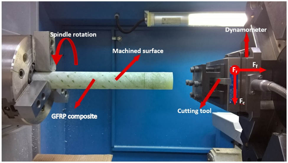
Experimental setup.
Dry condition turning experiments have been conducted on GFRP composite materials of tungsten carbide (WC) cutting tool TiAlN coated by using the PVD method, triangular YBG205 grade, TNMG 160404 EF insert cutting tool, S16M-PTFNR11 tool holder of ZCC CT company. The cutting parameters used in the experiments are indicated in Table 2. The cutting parameters were designated by means of the information obtained from cutting tools manufacturers and literature [22,23,24,25,27,28].
Cutting parameters used for experiments
| Cutting parameters | Value |
|---|---|
| Cutting speed (m·min−1) | 50, 100, and 150 |
| Feed rate (mm·rev−1) | 0.1, 0.2, and 0.3 |
| Depth of cut (mm) | 1, 2, and 3 |
| Fiber orientation (°) | 30, 60, and 90° |
| Cutting tool | WC, TiAlN coated |
A three-component Kistler type 9257B (Kistler Instruments AG, Winterthur, Switzerland) dynamometer was used to measure cutting force while performing the experiments, as shown in Figures 1 and 2. Kistler type 5070-A multi-channel amplifier was used to transfer the signals taken from the dynamometer in all cutting directions to the data acquisition card and linked to the computer. Then, Kistler Dynoware (V2.6.3.12) software was used to analyze and evaluate the collected data. The cutting force signals (all directions) were captured and filtered through a low-pass filter (10 Hz cutoff frequency). The filtered force graph taken from the DynoWare software is shown in Figure 3. Cutting force measurements were made in three directions as feed force (Ff), radial force (Fr), and cutting force (Fc). The resultant cutting force F was found as F = (Ff2 + Fr2 + Fc2)1/2 and used in the graphics.
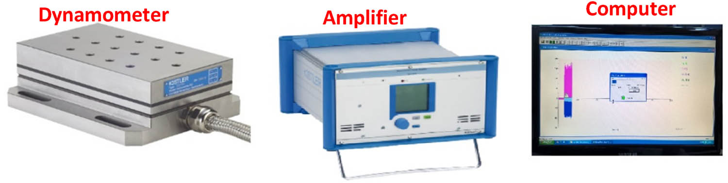
Cutting force measuring setup.
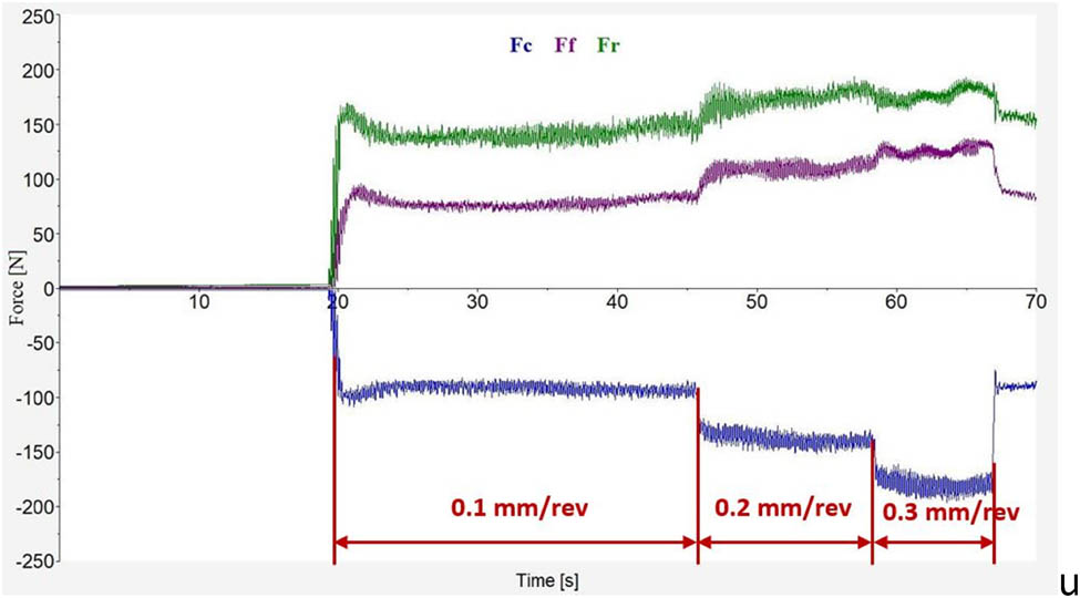
Fc, Ff, and Fr force diagrams in turning of GFRP composite.
The data plotted in Figure 3 are measured for the case GFRP 30° fiber orientation, 50 m·min−1 cutting speed, 0.1, 0.2 and 0.3 mm·rev−1 feed rate, and 3 mm depth of cut. While turning GFRP composites at different processing parameters, the surface roughness value (R a) of the machined surfaces was measured with the Time-TR-110 tester. Surface roughness measurements were carried out in accordance with ISO 4288 requirements. The measuring parameters were R a and R z, with a travel length of 6 mm. The cutoff length was determined as 2.5 mm. The range for roughness parameters (R a) were set as 0.05–15.0 µm. After the turning experiments were completed, the roughness of the machined surfaces was measured over the average of the roughness values measured at five different points.
3 Modeling the process with ANNs
To develop a dedicated soft system for simulating machining process of turning GFRP composites with different orientation angles, and different machining parameters, a particular ANN was designed using MATLAB software, as given in Figure 4a. The flowchart followed in the design of neural network aspired to determine the most appropriate cutting forces for the targeted minimum surface roughness is shown in Figure 4b. This ANN model was specifically designed for identifying cutting force and surface roughness in regard to cutting speed, feed rate, and depth of cut machining parameters. The model was trained with 80% of the data obtained from 81 experiments and tested for the remaining 20% of the data. The ANN was feed forward type with one input layer (4 neurons corresponding machining parameters) one hidden layer (10 neurons) and an output layer with two outputs one for cutting force and the other for surface roughness. As in the literature [41,42], the LM learning algorithm was preferred because of the speed and stability it provides in the training of ANN. The neurons were activated with tansig so-called hyperbolic activation function. The network was trained with machining parameters used in the experiments until the mean square error reached the lowest possible rate for each trial. The success rate for all cases was above 90%. With the use of this model variety of experiments can be conducted virtually.
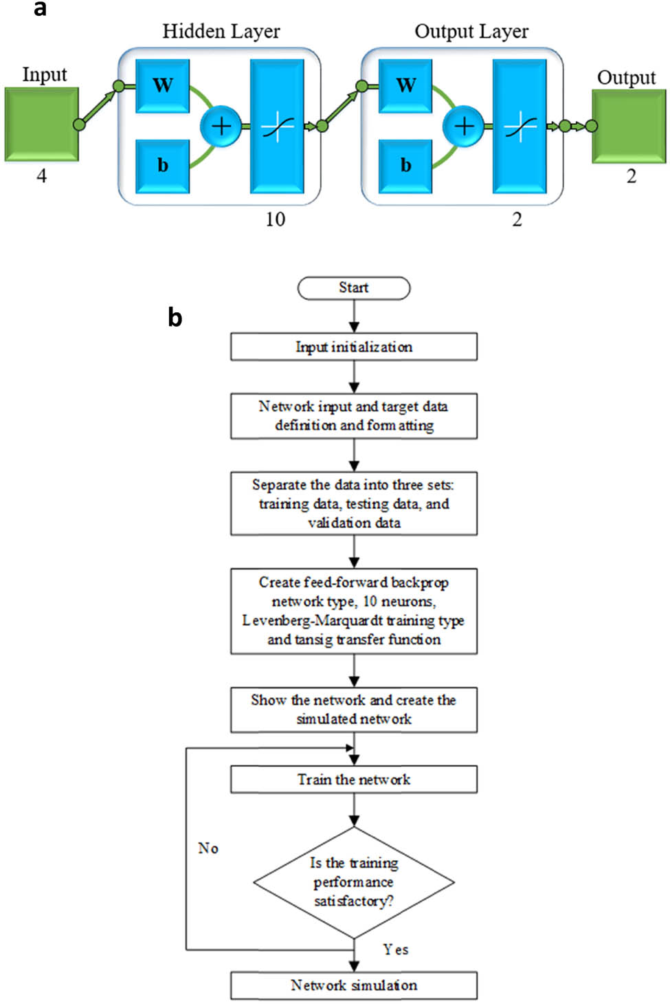
(a) ANN model. (b) Flowchart of neural network algorithm for determining cutting force and surface roughness.
4 Results and discussion
The results obtained from experimental part of the study demonstrated the correlation between cutting force and machining parameters. It was observed that fiber orientation angle highly effects cutting forces (Figures 5–7) mainly due to the increase in the compression stresses, which increases as the fiber’s orientation angle increases. The effects of feed rate on cutting force in turning GFRP composite at 30° fiber orientation angles and 1, 2, and 3 mm depths of cut are presented in Figure 5, while the effects of cutting speed and feed rate on cutting force at 30, 60, and 90° fiber orientation angles at 2 mm depth of cut are shown in Figures 6 and 7, respectively. In the process of machining GFRP composite pipe lower cutting forces (between 44 and 81 N) were observed with a 30° fiber orientation angle (Figure 5a) compared to those obtained at higher fiber orientation angles (Figures 6 and 7). This confirms the advantage of machining composite materials at low orientation angles [30,32]. At 30° fiber orientation angle, cutting forces were also varied in accordance with the feed rate as shown in Figure 5.
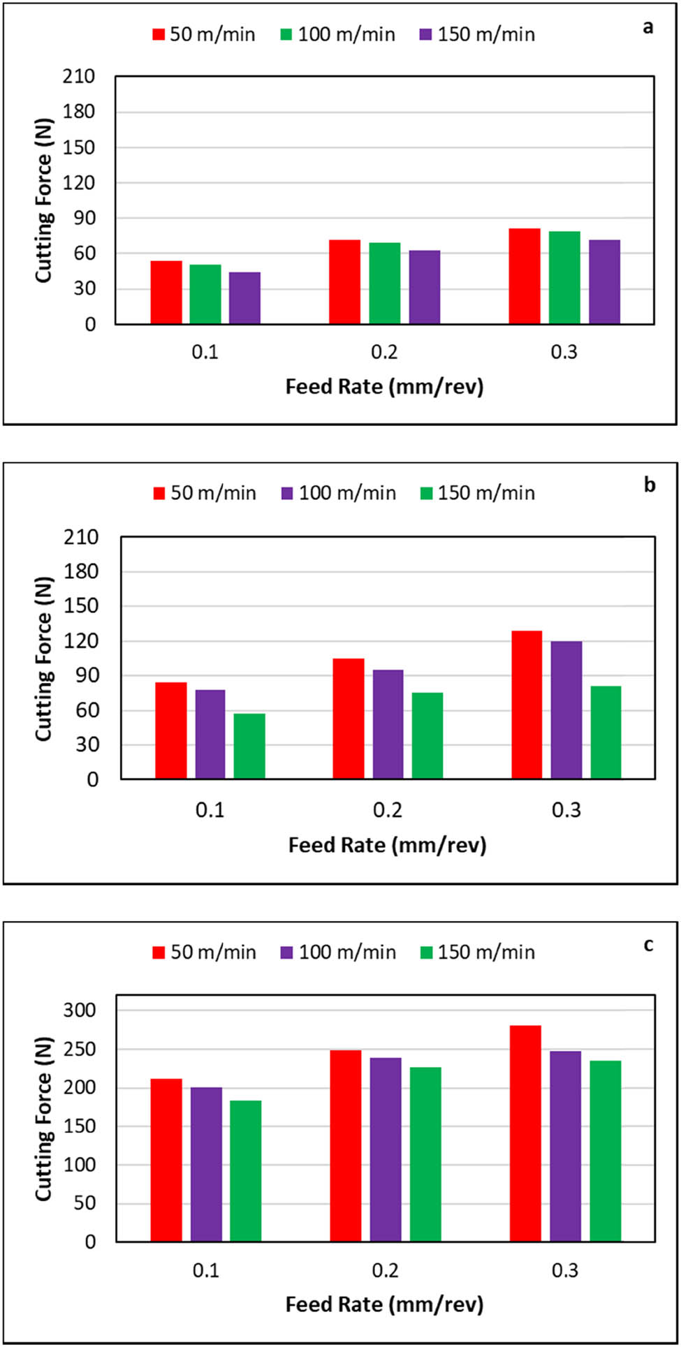
Influence of feed rate on cutting force at 30° fiber orientation: (a) depth of cut 1 mm, (b) depth of cut 2 mm, and (c) depth of cut 3 mm.
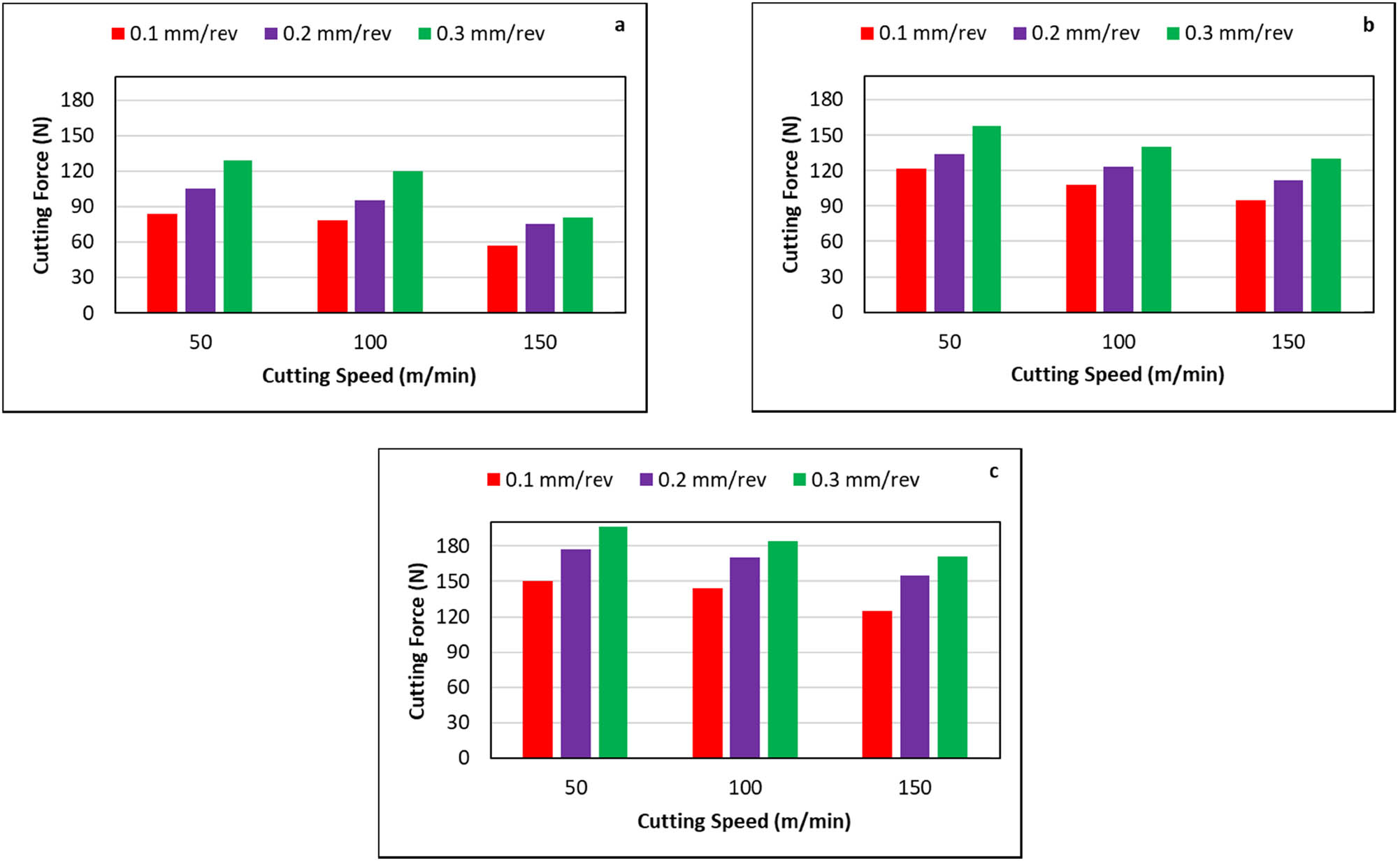
Influence of cutting speed on cutting force at constant depth of cut 2 mm: (a) fiber orientation 30°, (b) fiber orientation 60°, and (c) fiber orientation 90°.
The change in cutting forces with cutting speed is shown in Figure 6. As seen cutting forces decrease with the increase in cutting speed. The increase in cutting speed increases the temperature of the cutting zone. Increased temperature of the cutting zone causes softening of the matrix phase, resulting in lower cutting forces [46,47,48]. This result is in line with the data found in the literature [13,16,47,48]. Generally, in the processing of metals, high cutting speed is desirable for the high rate of production, but this increases tool wear [25]. The cutting force was also found as increasing with the increase of the feed rate (Figures 5 and 7), mainly due to the increase in the area of contact between the workpiece and cutting tool [1].
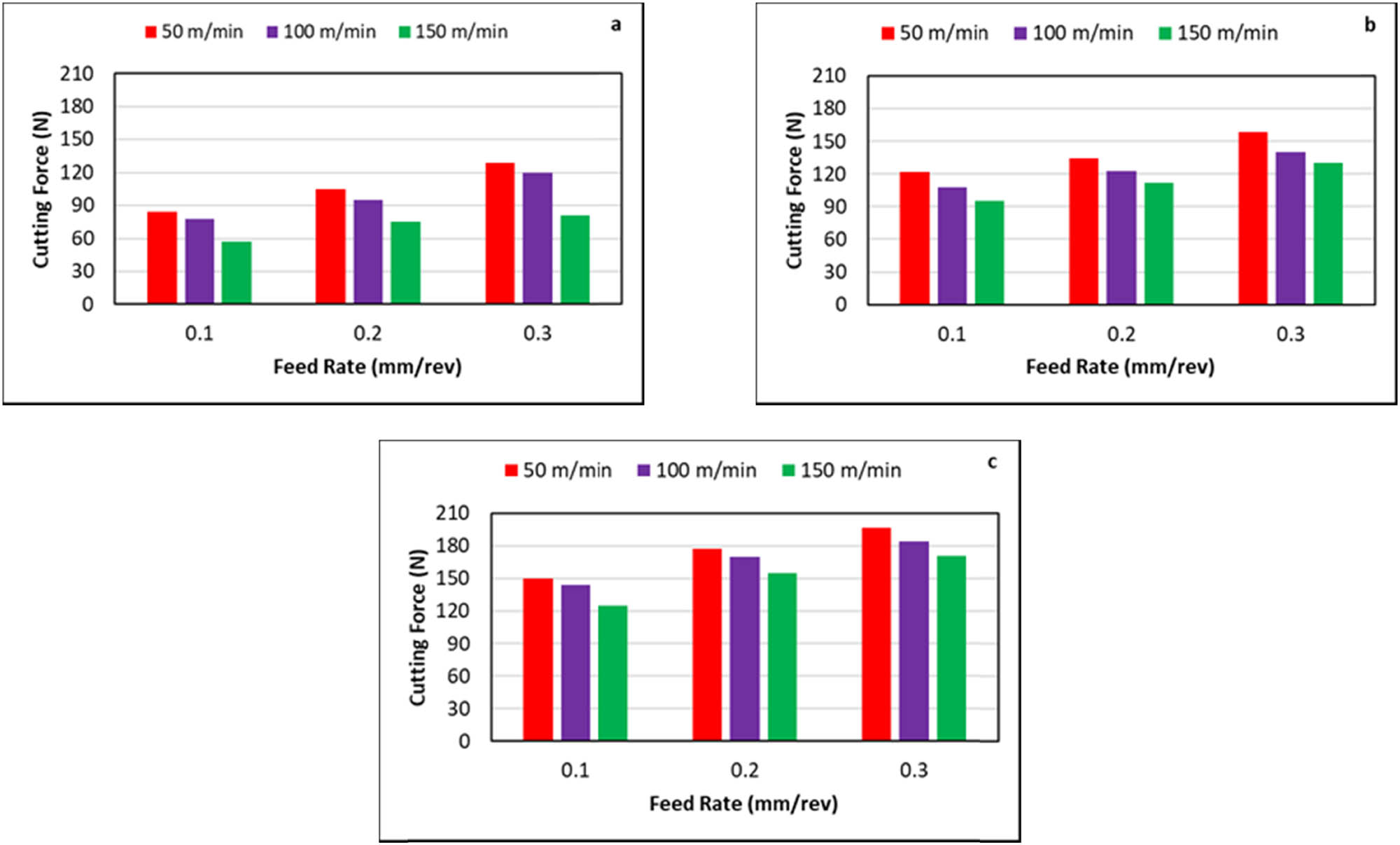
Influence of feed rate on cutting force at constant depth of cut 2 mm: (a) fiber orientation 30°, (b) fiber orientation 60°, and (c) fiber orientation 90°.
It is mentioned that about a quarter (approximately 23%; 119 EJ) of the total energy losses in the world is due to tribological systematics [49]. Improving the surface quality of the materials reduces friction and wear damage and hence energy loss, which is important for sustainable energy and economy of the future [50], on the one hand, and increases the strength of materials, on the other hand. In the machining of metals, the cutting speed is more effective than the feed rate [20,22,29,51] on the surface roughness.
Among these parameters, the depth of cut had a minimum effect compared to other machining parameters. Also, cutting force increased with the increase of depth of cut, which can be observed in Figure 5.
The effects of cutting parameters on surface roughness when machining carried out at 30, 60, and 90° fiber orientation angles were studied, and the results are represented in Figures 8–10. It was observed that parameters affecting surface roughness, from the most to the least, are fiber orientation, feed rate, cutting speed and depth of cut, which is in line with the literature [40].
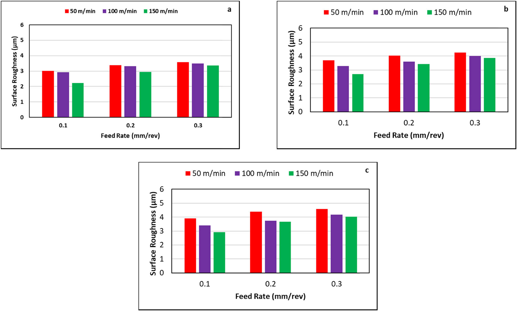
Influence of feed rate on surface roughness at 30° fiber orientation: (a) depth of cut 1 mm, (b) depth of cut 2 mm, and (c) depth of cut 3 mm.

Influence of cutting speed on surface roughness at constant depth of cut 2 mm: (a) fiber orientation 30°, (b) fiber orientation 60°, and (c) fiber orientation 90°.
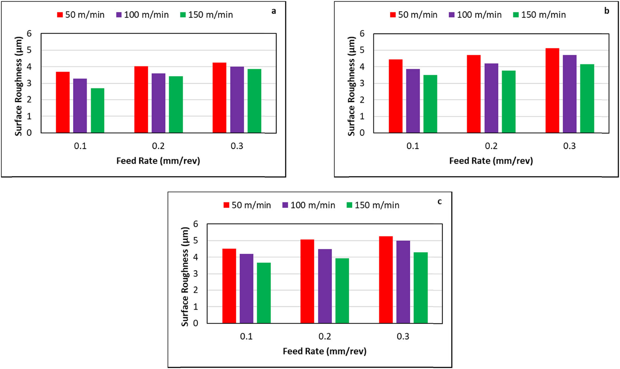
Influence of feed rate on surface roughness at constant depth of cut 2 mm: (a) fiber orientation 30°, (b) fiber orientation 60°, and (c) fiber orientation 90°.
As seen from Figure 8, at 30° fiber orientation angle, low surface roughness values ranging from 2.22 to 3.57 µm were observed in GFRP composite material at a constant depth of cut (1 mm) and feed rates (0.1, 0.2, and 0.3 mm·rev−1). Similarly, with the same scenario, at the 60° fiber orientation angle, the surface roughness value ranged from 3.46 to 4.47 µm, and at 90° fiber orientation angle, the surface roughness value ranged from 3.55 to 5.08 µm. In conclusion, the larger the fiber orientation angles, the higher the surface roughness rate values are obtained, which may be explained as that, larger fiber orientation angles create a greater compression stress on the workpiece material, which increases cutting force and consequently surface roughness [1,25,26,32].
The effect of feed rate on surface roughness with fiber orientations 30, 60, and 90° is shown in Figures 8 and 10. It is seen that the surface roughness increased gradually for three different depths of cut levels with the increase of feed rates of 0.1, 1.2, and 0.3 mm·rev−1. It can be seen from the figures that the cutting force increases with increasing feed rate and consequently surface roughness increases. This is may be explained as that an increase in feed rate causes an increase in vibration because of undercut at faster traverse, and this consequently causes an increase in surface roughness [51,52].
Figure 9 shows the variation in surface roughness with cutting speed at different feed rates. As seen, the surface roughness obtained at high cutting speed was better than that obtained at low cutting speed mainly due to softening in the material’s matrix caused by the heat generated in the workpiece at high speeds. The softening matrix material creates chip consisting of cut fibers that are less deformed during processing. Less deformed fibers cut with lower forces produces lower surface roughness [16,17,25,46,47,48].
From these experiments, it was observed that the surface roughness at 3 mm depth of cut was higher than at 1 mm depth of cut, as seen from Figure 8. Depth of cut has little effect on composite machining compared to cutting speed and feed rate [51]; however, higher depth of cut has a detrimental effect on surface quality in GFRP machining and, therefore, it is recommended to use a low depth of cut when machining GFRP composite materials [22,53].
All in all, the highest cutting force (306 N) was obtained at 0.3 mm·rev−1 feed rate, 90° fiber orientation angle, 3 mm depth of cut, and 50 m·min−1 cutting speed, where, in this case, 5.58 µm surface roughness was obtained. The lowest cutting force (44 N) was obtained at 0.1 mm·rev−1 feed rate (lowest feed rate), 30° fiber orientation angle (minimum fiber orientation angle), 1 mm depth of cut (minimum depth of cut), and 150 m·min−1 cutting speed (maximum cutting speed), where, in this case, minimum surface roughness 2.22 µm was obtained.
The maximum surface roughness was obtained at the highest feed rate (0.3 mm·rev−1), fiber orientation angle (90°), and depth of cut (3 mm), as shown in Figures 8–10, whereas the lowest surface roughness was observed for the lowest feed rate (0.1 mm·rev−1), fiber orientation angle (30°), and highest cutting speed.
Taking the cutting forces and surface roughness values obtained in the experimental part of the study as supervising reference the ANN model was designed with the input parameters are being the machining parameters used experimentally. For each of stages of the design process (training, validation, testing, and system), the obtained results are plotted and analyzed with regression process as shown in Figure 11, where the regression R values (on the top) and the linear regression equation (Y-axis) are shown on each of graphs.
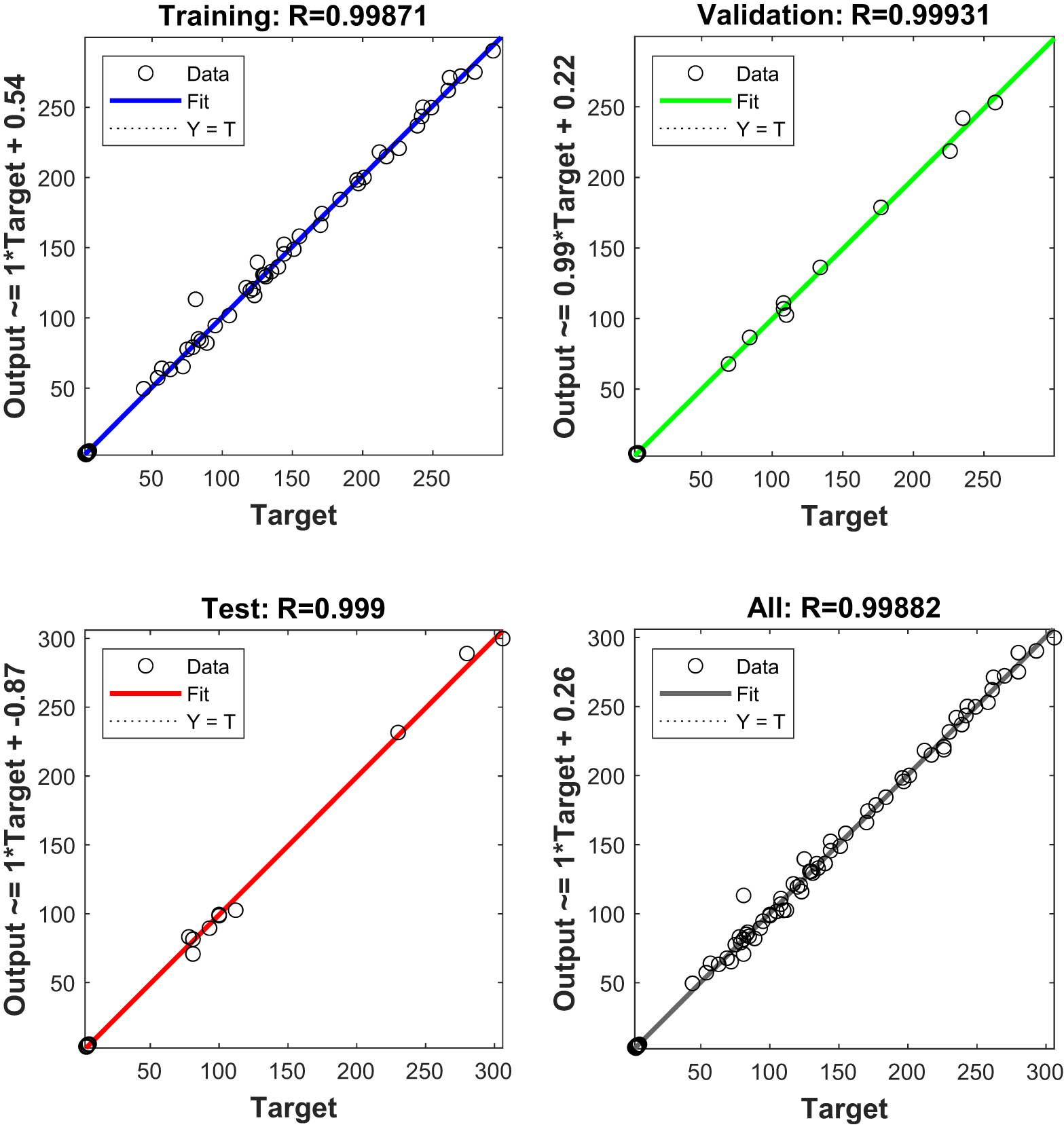
Regression model produced by the ANN model.
The results obtained with ANN model for cutting force and surface roughness are given in Table 3. These model-based artificial results are compared to those obtained from the experimental study for cutting force and surface roughness in Figures 12 and 13. From the figures, it is seen that ANN results are well fitted to the ones obtained with experiments. As seen in Figure 11, the confidence coefficient value obtained for ANN model both in training and test phases was 99%, which is higher than 95% accepted in prediction analysis. These results confirmed the suitability of the ANN in modeling the machining process.
Results from experimental study and ANN model
| Cutting parameters | Experimental results | ANN results | Error (%) | ||||||
|---|---|---|---|---|---|---|---|---|---|
| a (mm) | V c (m·min−1) | f (mm·rev−1) | Orientation angle (°) | F (N) | R a (µm) | F (N) | R a (µm) | F (N) | R a (µm) |
| 1 | 100 | 0.1 | 30 | 51 | 2.93 | 55.56 | 3.27 | 8.207 | 10.397 |
| 1 | 150 | 0.3 | 30 | 72 | 3.37 | 81.69 | 3.69 | 11.862 | 8.672 |
| 2 | 100 | 0.2 | 30 | 95 | 3.6 | 87.82 | 3.71 | 8.176 | 2.965 |
| 3 | 50 | 0.1 | 30 | 212 | 3.91 | 215.63 | 4.3 | 1.683 | 9.069 |
| 3 | 100 | 0.3 | 30 | 247 | 4.18 | 256.7 | 4.7 | 3.779 | 11.064 |
| 1 | 50 | 0.2 | 60 | 96 | 3.92 | 86.5 | 4.28 | 10.983 | 8.411 |
| 1 | 150 | 0.1 | 60 | 77 | 3.46 | 69.87 | 3.36 | 10.204 | 2.976 |
| 2 | 50 | 0.3 | 60 | 158 | 5.12 | 173.72 | 4.89 | 9.049 | 4.703 |
| 2 | 150 | 0.2 | 60 | 112 | 3.76 | 101.23 | 4.12 | 10.639 | 8.738 |
| 3 | 100 | 0.1 | 60 | 208 | 4.06 | 212.07 | 4.56 | 1.919 | 10.965 |
| 3 | 150 | 0.3 | 60 | 244 | 4.32 | 254.37 | 4.63 | 4.077 | 6.695 |
| 1 | 100 | 0.2 | 90 | 123 | 3.99 | 124.53 | 4.37 | 1.229 | 8.696 |
| 2 | 50 | 0.1 | 90 | 150 | 4.51 | 161.92 | 4.13 | 7.362 | 9.2 |
| 2 | 100 | 0.3 | 90 | 184 | 4.99 | 185.97 | 4.9 | 1.059 | 1.837 |
| 3 | 50 | 0.2 | 90 | 274 | 4.94 | 250.44 | 4.85 | 9.407 | 1.856 |
| 3 | 150 | 0.1 | 90 | 204 | 4.27 | 213.68 | 4.55 | 4.53 | 6.154 |
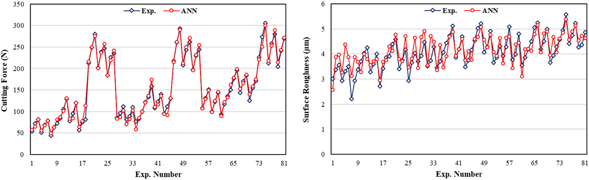
Comparison of experimental data with predicted results from ANN.
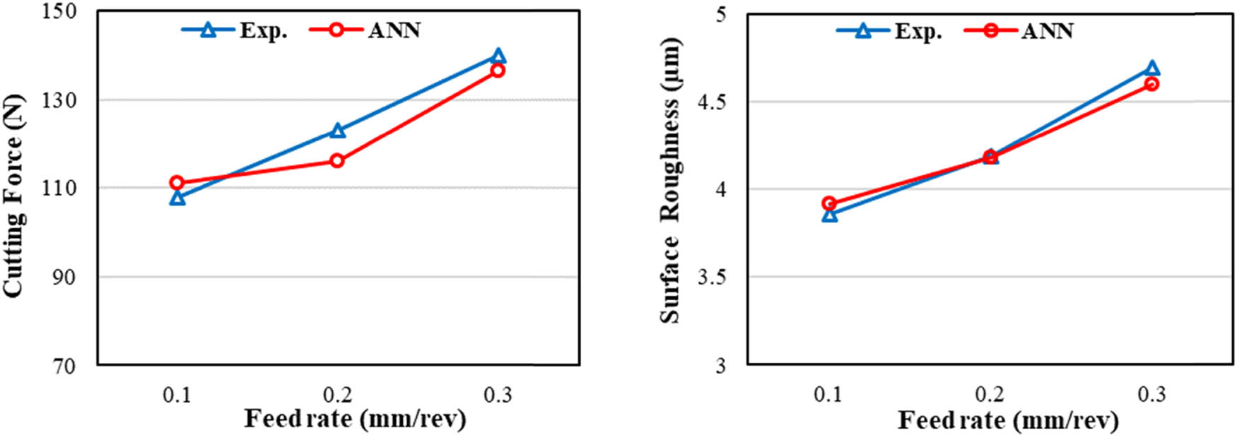
Comparison of experimental data and ANN for depth of cut 2 mm, cutting speed 100 m·min−1, and orientation angle 60°.
The success rate for all cases was above 90%. When the ANN model is trained, the weight vectors going between layers and the bias vector to each layer are shown in Table 4. Table 5 shows the comparison of results produced by ANN and experimental results obtained during the testing of the model. It can be observed that the results obtained from the experimental study and the ones obtained from ANN model are very close to each other. The experimentally obtained cutting force was 140 N at 2 mm depth of cut, 100 m·min−1 cutting speed, 60° fiber orientation angle, and 0.3 mm·rev−1 feed rate, whereas the estimated cutting force with ANN was found to be 136.36 N. The surface roughness value obtained experimentally with the same machining parameters was obtained as 4.7 µm. The estimated value with ANN was found to be 4.60 µm. As can be comprehended, a high agreement of 97.4 and 97.87%, respectively, were observed between the experimental results and ANN results. In both experimental and model-based analysis, the lowest cutting force and surface roughness were achieved at low fiber orientation angle, low feed rate and depth of cut and at high cutting speeds. These highly correlated values are validating the designed ANN model to confidently be used in machining process simulation. With such a model, variety of machining parameters can be tested in GFRP composite materials for obtaining perfect surface with a minimum cutting force.
Weight and bias values in ANN model
| Iw {1,1}-weight to layer 1 from input 1 | [−1.2592; −1.5571; −1.8251; 2.0482; −0.023451; −0.26534; 2.2684; 0.23592; 3.6965; 0.02574; −0.15156; 0.2392; 0.28629; −1.7235; 0.000973; −2.356; 0.80023; −0.39529; −1.3232; 0.26572; 0.7197; −0.2348; −2.6517; 0.05095−1.8867; −0.072011; −2.018; 1.0609; −0.67493; −1.2496; −0.33497; −1.1264; −1.1801; −0.23953; −1.7968; 0.67722−1.3526; 0.80845; 0.84801; 1.3338] |
| b {1}-bias to layer 1 | [1.0835; −2.8587; −0.49337; 0.38064; −0.18119; −0.37284; 1.5; −3.4599; −2.473; −2.3537] |
| Iw {2,1}-weight to layer | [0.11908; 0.44101; 0.58384; −0.0085291; 0.96606; −0.87526; −0.24475; −0.38488; 0.23032; 0.25378; 0.32094; 0.19434; 0.32731; 0.022901; 0.19761; −0.63468; 0.13446; −0.93047; 0.067842; −0.23836] |
| b {2}-bias to layer 2 | [0.30288; −0.8118] |
Validation results obtained from ANN and experimental study for different input parameters
| Cutting parameters | Experimental results | ANN results | Error (%) | ||||||
|---|---|---|---|---|---|---|---|---|---|
| a (mm) | V c (m·min−1) | f (mm·rev−1) | Orientation angle (°) | F (N) | R a (µm) | F (N) | R a (µm) | F (N) | R a (µm) |
| 1 | 90 | 0.15 | 30 | 50.47 | 3.25 | 53.89 | 3.65 | 6.35 | 10.96 |
| 1.5 | 130 | 0.25 | 60 | 71.14 | 4.13 | 78.47 | 4.23 | 9.34 | 2.36 |
| 2 | 80 | 0.3 | 90 | 177.45 | 5.01 | 188.4 | 5.43 | 5.81 | 7.73 |
| 2.5 | 150 | 0.15 | 30 | 112.14 | 3.29 | 121.08 | 3.38 | 7.38 | 2.66 |
| 3 | 70 | 0.2 | 60 | 248.56 | 4.16 | 259.89 | 4.61 | 4.36 | 9.76 |
| 1 | 120 | 0.25 | 90 | 109.89 | 4.12 | 120.07 | 4.29 | 8.48 | 3.96 |
| 2 | 70 | 0.1 | 30 | 85.23 | 3.4 | 88.77 | 3.54 | 3.98 | 3.95 |
| 2.5 | 100 | 0.3 | 60 | 245.65 | 4.33 | 251 | 4.71 | 2.13 | 8.07 |
| 3 | 140 | 0.25 | 90 | 267.09 | 4.65 | 279.4 | 4.95 | 4.4 | 6.06 |
5 Conclusions
In this study, experimental results were obtained by turning GFRP composites from various aspects and an ANN model was developed using these data. With this artificial model, the effects of fiber orientation, cutting speed, feed rate, and depth of cut on the cutting force and surface roughness values were estimated. While developing the model, orientation angle, cutting speed, feed rate, and depth of cut were taken as input features and fed to the input of the ANN model. The output was cutting force and surface roughness. From this study, the following were deduced.
The highest cutting force (306 N) and maximum surface roughness (5.58 µm) were obtained at maximum feed rate (0.3 mm·rev−1), fiber orientation (90°), depth of cut (3 mm), and minimum cutting speed (50 m·min−1).
Minimum cutting force (44 N) and surface roughness (2.22 µm) were obtained at 0.1 mm·rev−1 feed rate (lowest feed rate), 30° fiber orientation angle (minimum fiber orientation angle), 1 mm depth of cut (minimum depth of cut), and 150 m·min−1 cutting speed (maximum cutting speed).
Increasing fiber orientation angle, feed rate and depth of cut increased the cutting force and surface roughness.
Increasing the cutting speed decreased the cutting force and surface roughness.
The values obtained from ANN were very close to the data obtained from experimental studies.
From the results obtained from the experiments and ANN model, it is confirmed that the developed model can be used effectively to predict cutting force and surface roughness with respect to variations in machining parameters including fiber’s orientation angle.
ANN model had predicted cutting force and surface roughness values accurately.
-
Funding information: This study received no external funding.
-
Author contribution: The author has accepted responsibility for the entire content of this article and approved its submission.
-
Conflict of interest: The author (Ahmet Yardimeden) declares that there is no conflict of interest.
References
[1] Çelik, Y. H., E. Kilickap, and A. İ. Kilickap. An experimental study on milling of natural fiber (Jute)- reinforced polymer composites. Journal of Composite Materials, Vol. 53, No. 22, 2019, pp. 3127–3137.10.1177/0021998319826373Suche in Google Scholar
[2] Panchagnula, K. K. and K. Palaniyandi. Drilling on fiber reinforced polymer/nanopolymer composite laminates: A review. Journal of Materials Research and Technology, Vol. 7, No. 2, 2018, pp. 180–189.10.1016/j.jmrt.2017.06.003Suche in Google Scholar
[3] Cai, X., X. Bo, P. Feng, X. Ren, X. Kang, C. Xu, and P. Zhang. Porous NbAl3/TiAl3 intermetallic composites with controllable porosity and pore morphology prepared by two-step thermal explosion. Journal of Materials Research and Technology, Vol. 8, No. 3, 2019, pp. 3188–3197.10.1016/j.jmrt.2019.05.007Suche in Google Scholar
[4] Kiliçkap, E., A. Yardimeden, and Y. H. Çelik. Investigation of experimental study of end milling of CFRP composite. Science and Engineering of Composite Materials, Vol. 22, No. 1, 2015, pp. 89–95.10.1515/secm-2013-0143Suche in Google Scholar
[5] Bhat, R., N. Mohan, S. Sharma, A. Pratap, A. P. Keni, and D. Sodani. Mechanical testing and microstructure characterization of glass fiber reinforced isophthalic polyester composites. Journal of Materials Research and Technology, Vol. 8, No. 4, 2019, pp. 3653–3661.10.1016/j.jmrt.2019.06.003Suche in Google Scholar
[6] Ekici, E., A. R. Motorcu, and E. Yıldırım. An experimental study on hole quality and different delamination approaches in the drilling of CARALL, a New FML composite. FME Transactions, Vol. 49, No. 4, 2021, pp. 950–961.10.5937/fme2104950ESuche in Google Scholar
[7] Mkaddem, A., A. Ben Soussia, and M. El Mansori. Wear resistance of CVD and PVD multilayer coatings when dry cutting fiber reinforced polymers (FRP). Wear, Vol. 302, No. 1–2, 2013, pp. 946–954.10.1016/j.wear.2013.03.017Suche in Google Scholar
[8] IşIk, B. and A. Kentli. Multicriteria optimization of cutting parameters in turning of UD-GFRP materials considering sensitivity. International Journal of Advanced Manufacturing Technology, Vol. 44, No. 11–12, 2009, pp. 1144–1153.10.1007/s00170-009-1927-9Suche in Google Scholar
[9] Khan, M. A., S. P. Jani, A. S. Kumar, and S. Rajesh. Machining parameter optimization using adam – gene algorithm while turning lightweight composite using ceramic cutting tools. International Journal of Lightweight Materials and Manufacture, Vol. 4, No. 2, 2021, pp. 262–267.10.1016/j.ijlmm.2020.12.005Suche in Google Scholar
[10] Khan, M. A., A. S. Kumar, and A. Poomari. A hybrid algorithm to optimize cutting parameter for machining GFRP composite using alumina cutting tools. International Journal of Advanced Manufacturing Technology, Vol. 59, No. 9–12, 2012, pp. 1047–1056.10.1007/s00170-011-3553-6Suche in Google Scholar
[11] Davim, J. P. and F. Mata. A new machinability index in turning fiber reinforced plastics. Journal of Materials Processing Technology, Vol. 170, No. 1–2, 2005, pp. 436–440.10.1016/j.jmatprotec.2005.05.047Suche in Google Scholar
[12] Davim, J. P. and F. Mata. Optimisation of surface roughness on turning fibre-reinforced plastics (FRPs) with diamond cutting tools. International Journal of Advanced Manufacturing Technology, Vol. 26, No. 4, 2005, pp. 319–323.10.1007/s00170-003-2006-2Suche in Google Scholar
[13] Palanikumar, K., F. Mata, and J. P. Davim. Analysis of surface roughness parameters in turning of FRP tubes by PCD tool. Journal of Materials Processing Technology, Vol. 204, No. 1–3, 2008, pp. 469–474.10.1016/j.jmatprotec.2007.12.088Suche in Google Scholar
[14] Naveen Sait, A., S. Aravindan, and A. Noorul Haq. Optimisation of machining parameters of glass-fibre-reinforced plastic (GFRP) pipes by desirability function analysis using taguchi technique. International Journal of Advanced Manufacturing Technology, Vol. 43, No. 5–6, 2009, pp. 581–589.10.1007/s00170-008-1731-ySuche in Google Scholar
[15] Çelik, Y. H. and C. Türkan. Investigation of mechanical characteristics of GFRP composites produced from chopped glass fiber and application of taguchi methods to turning operations. SN Applied Sciences, Vol. 2, No. 5, 2020, id. 849.10.1007/s42452-020-2684-5Suche in Google Scholar
[16] Ficici, F., Z. Ayparcasi, and H. Unal. Influence of cutting tool and conditions on machinability aspects of polyphthalamide (PPA) matrix composite materials with 30 % glass fiber reinforced. International Journal of Advanced Manufacturing Technology, Vol. 90, No. 9–12, 2017, pp. 3067–3073.10.1007/s00170-016-9626-9Suche in Google Scholar
[17] Mudhukrishnan, M., P. Hariharan, K. Palanikumar, and B. Latha. Tool materials influence on surface roughness and oversize in machining glass fiber reinforced polypropylene (GFR-PP) composites. Materials and Manufacturing Processes, Vol. 32, No. 9, 2017, pp. 988–997.10.1080/10426914.2016.1221098Suche in Google Scholar
[18] Henerichs, M., R. Voß, F. Kuster, and K. Wegener. Machining of carbon fiber reinforced plastics: Influence of tool geometry and fiber orientation on the machining forces. CIRP Journal of Manufacturing Science and Technology, Vol. 9, No. 4, 2015, pp. 136–145.10.1016/j.cirpj.2014.11.002Suche in Google Scholar
[19] Gupta, M. and S. K. Gill. Prediction of cutting force in turning of UD-GFRP using mathematical model and simulated annealing. Frontiers of Mechanical Engineering, Vol. 7, No. 4, 2012, pp. 417–426.10.1007/s11465-012-0343-2Suche in Google Scholar
[20] Gupta, M. and S. Kumar. Investigation of surface roughness and MRR for turning of UD-GFRP using PCA and taguchi method. Engineering Science and Technology, an International Journal, Vol. 18, No. 1, 2015, pp. 70–81.10.1016/j.jestch.2014.09.006Suche in Google Scholar
[21] Gill, S. K., M. Gupta, and P. S. Satsangi. Prediction of cutting forces in machining of unidirectional glass fiber reinforced plastics composite. Frontiers of Mechanical Engineering, Vol. 8, No. 2, 2013, pp. 187–200.10.1007/s11465-013-0262-xSuche in Google Scholar
[22] Kini, M. V. and A. M. Chincholkar. Effect of machining parameters on surface roughness and material removal rate in finish turning of ± 30° glass fibre reinforced polymer pipes. Materials and Design, Vol. 31, No. 7, 2010, pp. 3590–3598.10.1016/j.matdes.2010.01.013Suche in Google Scholar
[23] Fetecau, C. and F. Stan. Study of cutting force and surface roughness in the turning of polytetrafluoroethylene composites with a polycrystalline diamond tool. Measurement: Journal of the International Measurement Confederation, Vol. 45, No. 6, 2012, pp. 1367–1379.10.1016/j.measurement.2012.03.030Suche in Google Scholar
[24] Kumar, S., M. Gupta, and P. S. Satsangi. Multiple-response optimization of cutting forces in turning of UD-GFRP composite using distance-based pareto genetic algorithm approach. Engineering Science and Technology, an International Journal, Vol. 18, No. 4, 2015, pp. 680–695.10.1016/j.jestch.2015.04.010Suche in Google Scholar
[25] Azmi, A. I., R. J. T. T. Lin, and D. Bhattacharyya. Experimental study of machinability of GFRP composites by end milling. Materials and Manufacturing Processes, Vol. 27, No. 10, 2012, pp. 1045–1050.10.1080/10426914.2012.677917Suche in Google Scholar
[26] Lopresto, V., A. Langella, G. Caprino, M. Durante, and L. Santo. Conventional orthogonal cutting machining on unidirectional fibre reinforced plastics. Procedia CIRP, Vol. 62, 2017, pp. 9–14.10.1016/j.procir.2016.07.036Suche in Google Scholar
[27] Hintze Wolfgang, W., D. Hartmann, and C. Schütte. Occurrence and propagation of delamination during the machining of carbon fibre reinforced plastics (CFRPs) - An experimental study. Composites Science and Technology, Vol. 71, No. 15, 2011, pp. 1719–1726.10.1016/j.compscitech.2011.08.002Suche in Google Scholar
[28] Chen, L., K. Zhang, H. Cheng, Z. Qi, and Q. Meng. A cutting force predicting model in orthogonal machining of unidirectional CFRP for entire range of fiber orientation. International Journal of Advanced Manufacturing Technology, Vol. 89, No. 1–4, 2017, pp. 833–846.10.1007/s00170-016-9059-5Suche in Google Scholar
[29] Palanikumar, K., L. Karunamoorthy, and R. Karthikeyan. Multiple performance optimization of machining parameters on the machining of GFRP composites using carbide (K10) tool. Materials and Manufacturing Processes, Vol. 21, No. 8, 2006, pp. 846–852.10.1080/03602550600728166Suche in Google Scholar
[30] Koplev, A., A. Lystrup, and T. Vorm. The cutting process, chips, and cutting forces in machining CFRP. Composites, Vol. 14, No. 4, 1983, pp. 371–376.10.1016/0010-4361(83)90157-XSuche in Google Scholar
[31] Lopresto, V., A. Caggiano, and R. Teti. High performance cutting of fibre reinforced plastic composite materials. Procedia CIRP, Vol. 46, 2016, pp. 71–82.10.1016/j.procir.2016.05.079Suche in Google Scholar
[32] Palanikumar, K. Modeling and analysis for surface roughness in machining glass fibre reinforced plastics using response surface methodology. Materials and Design, Vol. 28, No. 10, 2007, pp. 2611–2618.10.1016/j.matdes.2006.10.001Suche in Google Scholar
[33] Khashaba, U. A., M. S. Abd-Elwahed, M. A. Eltaher, I. Najjar, A. Melaibari, and K. I. Ahmed. Thermo-mechanical and delamination properties in drilling gfrp composites by various drill angles. Polymers, Vol. 13, No. 11, 2021, id. 1884.10.3390/polym13111884Suche in Google Scholar PubMed PubMed Central
[34] Khashaba, U. A., M. S. Abd-Elwahed, I. Najjar, A. Melaibari, K. I. Ahmed, R. Zitoune, and M. A. Eltaher. Heat-affected zone and mechanical analysis of GFRP composites with different thicknesses in drilling processes. Polymers, Vol. 13, No. 14, 2021, id. 2246.10.3390/polym13142246Suche in Google Scholar PubMed PubMed Central
[35] Neeli, N., M. P. Jenarthanan, and G. Dileep Kumar. Multi-response optimization for machining GFRP composites using GRA and DFA. Multidiscipline Modeling in Materials and Structures, Vol. 14, No. 3, 2018, pp. 482–496.10.1108/MMMS-08-2017-0092Suche in Google Scholar
[36] Mansour, G., P. Kyratsis, A. Korlos, and D. Tzetzis. Investigation into the effect of cutting conditions in turning on the surface properties of filament winding gfrp pipe rings. Machines, Vol. 9, No. 1, 2021, pp. 1–15.10.3390/machines9010016Suche in Google Scholar
[37] Ekici, E., A. R. Motorcu. Optimization of Surface Roughness, Delamination and Uncut Fiber Factor in the Drilling of CFRP Composites. 1st International Conference of Advanced Materials and Manufacturing Technologies (ICAMT’ 17) 25-27 October 2017, Safranbolu, Karabuk, Turkey, No. December 2017, 2017.Suche in Google Scholar
[38] Motorcu, A. R., E. Ekici. Cam Laminat Alüminyum Takviyeli Epoksinin (Glare) Özel Geometrili Matkaplarla Delinmesi: Delaminasyon Faktörü Üzerine Bir Çalışma. The International Conference of Materials and Engineering Technology (TICMET’20) will be held at Gaziantep University on 05-07 November 2020, No. December, 2020.Suche in Google Scholar
[39] Erkan, Ö., B. Işık, A. Çiçek, and F. Kara. Prediction of damage factor in end milling of glass fibre reinforced plastic composites using artificial neural network. Applied Composite Materials, Vol. 20, No. 4, 2013, pp. 517–536.10.1007/s10443-012-9286-3Suche in Google Scholar
[40] Jenarthanan, M. P., S. R. Kumar, and R. Jeyapaul. Modelling of machining force in end milling of GFRP composites using MRA and ANN. Australian Journal of Mechanical Engineering, Vol. 14, No. 2, 2016, pp. 104–114.10.1080/14484846.2015.1093227Suche in Google Scholar
[41] Ghosh, G., P. Mandal, and S. C. Mondal. Modeling and optimization of surface roughness in keyway milling using ANN, genetic algorithm, and particle swarm optimization. The International Journal of Advanced Manufacturing Technology, Vol. 100, No. 5, 2019, pp. 1223–1242.10.1007/s00170-017-1417-4Suche in Google Scholar
[42] Mishra, R. and B. Singh. Prediction of milling chatter using SBLMD-ANN. Journal of Mechanical Science and Technology, Vol. 36, No. 2, 2022, pp. 877–882.10.1007/s12206-022-0135-5Suche in Google Scholar
[43] Gordon, S. and M. T. Hillery. A review of the cutting of composite materials. Proceedings of the Institution of Mechanical Engineers Part L: Journal of Materials: Design and Applications, Vol. 217, No. 1, 2003, pp. 35–45.10.1177/146442070321700105Suche in Google Scholar
[44] König, W., C. Wulf, P. Graß, and H. Willerscheid. Machining of fibre reinforced plastics. CIRP Annals - Manufacturing Technology, Vol. 34, No. 2, 1985, pp. 537–548.10.1016/S0007-8506(07)60186-3Suche in Google Scholar
[45] Hussain, S. A., V. Pandurangadu, and K. Palanikumar. Surface roughness analysis in machining of GFRP composites by carbide tool (K20). European Journal of Scientific Research, Vol. 41, No. 1, 2010, pp. 84–98.Suche in Google Scholar
[46] Okay, F., S. Islak, and Y. Turgut. Investigation of machinability properties of aluminium matrix hybrid composites. Journal of Manufacturing Processes, Vol. 68, No. PA, 2021, pp. 85–94.10.1016/j.jmapro.2021.05.041Suche in Google Scholar
[47] Çelik, Y. H. and M. S. Alp. Determination of milling performance of jute and flax fiber reinforced composites. Journal of Natural Fibers, Vol. 19, No. 2, 2022, pp. 782–796.10.1080/15440478.2020.1764435Suche in Google Scholar
[48] Bayraktar, Ş. and Y. Turgut. Determination of delamination in drilling of carbon fiber reinforced carbon matrix composites/Al 6013-T651 stacks. Measurement: Journal of the International Measurement Confederation, Vol. 154, 2020, p. 107493.10.1016/j.measurement.2020.107493Suche in Google Scholar
[49] Holmberg, K. and A. Erdemir. Influence of tribology on global energy consumption, costs and emissions. Friction, Vol. 5, 2017, pp. 263–284.10.1007/s40544-017-0183-5Suche in Google Scholar
[50] Sayfidinov, K., S. D. Cezan, B. Baytekin, and H. T. Baytekin. Minimizing friction, wear, and energy losses by eliminating contact charging. Science Advances, Vol. 4, No. 11, 2018, p. eaau3808.10.1126/sciadv.aau3808Suche in Google Scholar PubMed PubMed Central
[51] Palanikumar, K., L. Karunamoorthy, and R. Karthikeyan. Assessment of factors influencing surface roughness on the machining of glass fiber-reinforced polymer composites. Materials and Design, Vol. 27, No. 10, 2006, pp. 862–871.10.1016/j.matdes.2005.03.011Suche in Google Scholar
[52] Kumar, S., Meenu, P. S. Satsangi, and H. K. Sardana. Optimization of surface roughness in turning unidirectional glass fiber reinforced plastics (UD-GFRP) composites using polycrystalline diamond (PCD) cutting tool. Indian Journal of Engineering and Materials Sciences, Vol. 19, No. 3, 2012, pp. 163–174.Suche in Google Scholar
[53] An, S. O., E. S. Lee, and S. L. Noh. A study on the cutting characteristics of glass fiber reinforced plastics with respect to tool materials and geometries. Journal of Materials Processing Technology, Vol. 68, No. 1, 1997, pp. 60–67.10.1016/S0924-0136(96)02534-4Suche in Google Scholar
© 2022 the author(s), published by De Gruyter
This work is licensed under the Creative Commons Attribution 4.0 International License.
Artikel in diesem Heft
- Review Articles
- State of the art, challenges, and emerging trends: Geopolymer composite reinforced by dispersed steel fibers
- A review on the properties of concrete reinforced with recycled steel fiber from waste tires
- Copper ternary oxides as photocathodes for solar-driven CO2 reduction
- Properties of fresh and hardened self-compacting concrete incorporating rice husk ash: A review
- Basic mechanical and fatigue properties of rubber materials and components for railway vehicles: A literature survey
- Research progress on durability of marine concrete under the combined action of Cl− erosion, carbonation, and dry–wet cycles
- Delivery systems in nanocosmeceuticals
- Study on the preparation process and sintering performance of doped nano-silver paste
- Analysis of the interactions between nonoxide reinforcements and Al–Si–Cu–Mg matrices
- Research Articles
- Study on the influence of structural form and parameters on vibration characteristics of typical ship structures
- Deterioration characteristics of recycled aggregate concrete subjected to coupling effect with salt and frost
- Novel approach to improve shale stability using super-amphiphobic nanoscale materials in water-based drilling fluids and its field application
- Research on the low-frequency multiline spectrum vibration control of offshore platforms
- Multiple wide band gaps in a convex-like holey phononic crystal strip
- Response analysis and optimization of the air spring with epistemic uncertainties
- Molecular dynamics of C–S–H production in graphene oxide environment
- Residual stress relief mechanisms of 2219 Al–Cu alloy by thermal stress relief method
- Characteristics and microstructures of the GFRP waste powder/GGBS-based geopolymer paste and concrete
- Development and performance evaluation of a novel environmentally friendly adsorbent for waste water-based drilling fluids
- Determination of shear stresses in the measurement area of a modified wood sample
- Influence of ettringite on the crack self-repairing of cement-based materials in a hydraulic environment
- Multiple load recognition and fatigue assessment on longitudinal stop of railway freight car
- Synthesis and characterization of nano-SiO2@octadecylbisimidazoline quaternary ammonium salt used as acidizing corrosion inhibitor
- Perforated steel for realizing extraordinary ductility under compression: Testing and finite element modeling
- The influence of oiled fiber, freeze-thawing cycle, and sulfate attack on strain hardening cement-based composites
- Perforated steel block of realizing large ductility under compression: Parametric study and stress–strain modeling
- Study on dynamic viscoelastic constitutive model of nonwater reacted polyurethane grouting materials based on DMA
- Mechanical behavior and mechanism investigation on the optimized and novel bio-inspired nonpneumatic composite tires
- Effect of cooling rate on the microstructure and thermal expansion properties of Al–Mn–Fe alloy
- Research on process optimization and rapid prediction method of thermal vibration stress relief for 2219 aluminum alloy rings
- Failure prevention of seafloor composite pipelines using enhanced strain-based design
- Deterioration of concrete under the coupling action of freeze–thaw cycles and salt solution erosion
- Creep rupture behavior of 2.25Cr1Mo0.25V steel and weld for hydrogenation reactors under different stress levels
- Statistical damage constitutive model for the two-component foaming polymer grouting material
- Nano-structural and nano-constraint behavior of mortar containing silica aggregates
- Influence of recycled clay brick aggregate on the mechanical properties of concrete
- Effect of LDH on the dissolution and adsorption behaviors of sulfate in Portland cement early hydration process
- Comparison of properties of colorless and transparent polyimide films using various diamine monomers
- Study in the parameter influence on underwater acoustic radiation characteristics of cylindrical shells
- Experimental study on basic mechanical properties of recycled steel fiber reinforced concrete
- Dynamic characteristic analysis of acoustic black hole in typical raft structure
- A semi-analytical method for dynamic analysis of a rectangular plate with general boundary conditions based on FSDT
- Research on modification of mechanical properties of recycled aggregate concrete by replacing sand with graphite tailings
- Dynamic response of Voronoi structures with gradient perpendicular to the impact direction
- Deposition mechanisms and characteristics of nano-modified multimodal Cr3C2–NiCr coatings sprayed by HVOF
- Effect of excitation type on vibration characteristics of typical ship grillage structure
- Study on the nanoscale mechanical properties of graphene oxide–enhanced shear resisting cement
- Experimental investigation on static compressive toughness of steel fiber rubber concrete
- Study on the stress field concentration at the tip of elliptical cracks
- Corrosion resistance of 6061-T6 aluminium alloy and its feasibility of near-surface reinforcements in concrete structure
- Effect of the synthesis method on the MnCo2O4 towards the photocatalytic production of H2
- Experimental study of the shear strength criterion of rock structural plane based on three-dimensional surface description
- Evaluation of wear and corrosion properties of FSWed aluminum alloy plates of AA2020-T4 with heat treatment under different aging periods
- Thermal–mechanical coupling deformation difference analysis for the flexspline of a harmonic drive
- Frost resistance of fiber-reinforced self-compacting recycled concrete
- High-temperature treated TiO2 modified with 3-aminopropyltriethoxysilane as photoactive nanomaterials
- Effect of nano Al2O3 particles on the mechanical and wear properties of Al/Al2O3 composites manufactured via ARB
- Co3O4 nanoparticles embedded in electrospun carbon nanofibers as free-standing nanocomposite electrodes as highly sensitive enzyme-free glucose biosensors
- Effect of freeze–thaw cycles on deformation properties of deep foundation pit supported by pile-anchor in Harbin
- Temperature-porosity-dependent elastic modulus model for metallic materials
- Effect of diffusion on interfacial properties of polyurethane-modified asphalt–aggregate using molecular dynamic simulation
- Experimental study on comprehensive improvement of shear strength and erosion resistance of yellow mud in Qiang Village
- A novel method for low-cost and rapid preparation of nanoporous phenolic aerogels and its performance regulation mechanism
- In situ bow reduction during sublimation growth of cubic silicon carbide
- Adhesion behaviour of 3D printed polyamide–carbon fibre composite filament
- An experimental investigation and machine learning-based prediction for seismic performance of steel tubular column filled with recycled aggregate concrete
- Effects of rare earth metals on microstructure, mechanical properties, and pitting corrosion of 27% Cr hyper duplex stainless steel
- Application research of acoustic black hole in floating raft vibration isolation system
- Multi-objective parametric optimization on the EDM machining of hybrid SiCp/Grp/aluminum nanocomposites using Non-dominating Sorting Genetic Algorithm (NSGA-II): Fabrication and microstructural characterizations
- Estimating of cutting force and surface roughness in turning of GFRP composites with different orientation angles using artificial neural network
- Displacement recovery and energy dissipation of crimped NiTi SMA fibers during cyclic pullout tests