Statistical damage constitutive model for the two-component foaming polymer grouting material
-
Mingrui Du
 ,
Hongyuan Fang
,
Hongyuan Fang

Abstract
Two-component foaming polymer (TFPU) grouting material is increasingly used in civil engineering. Its compressive strength is key to achieving the desired enhancing effect. The constitutive model of TFPU grouting material is a theoretical basis to evaluate the strength performance, which, however, is not fully understood. Here the uniaxial compression experiment of TFPU samples of different densities (0.11–0.53 g·cm−3) was conducted. Based on the stress–strain curves, the damage evolution equation of each sample was obtained by function fitting, followed by the establishment of statistical damage constitutive model. The model was simplified to a universal function with density as the argument. Results show that the stress–strain curves contain the initial compression stage, linear elastic stage, yield stage, yield plateau stage, and strain hardening stage regardless of the varied density. The variation laws of the damage with strain conform to the form of first-order decay exponential function. The theoretical stress–strain curves are in good agreement with the experimental ones, indicating that the statistical damage constitutive model can well reflect the mechanical behavior of TFPU grouting material. With this constitutive model, the mechanical properties of TFPU grouting material can be obtained according to the density alone, which is more convenient for practical engineering applications.
1 Introduction
Grouting has been the most widely used enhancement in civil engineering [1]. The traditional grouting materials often refer to the mixtures of cement, sand, and water that can provide strength after hardening [2,3]. Currently, the two-component foaming polymer (TFPU) grouting material is more increasingly used in grouting projects as replacement of cement-based grouts [4,5,6]. As the product of polymerization reaction between the isocyanate and polyol [7], TFPU grouting material has been characterized as low density, fast setting, large expansion force, strong permeability resistance, strong durability, and eco-friendly [7,8,9,10], by virtue of which, it has found applications in the consolidation of the loose soil mass [5,10], the rehabilitation of the settled infrastructures [4,6,11], the reinforcement of the fractured rock [12,13], and the leakage prevention of dams or underground buildings [14,15,16].
Figure 1 shows the representative applications of TFPU grouting material in practice. In practical engineering, TFPU grouting material produces a large expansion force that can raise the settled roadbeds [17], underground pipelines [11], and other infrastructures [6]. Besides, TFPU grouting material bears the vertical load that origins from the weight of the soil and engineering structures above it all the time [18]. The strength performance of TFPU grouting material is the key to achieving long-term reinforcement [4,5,11]. Under external load, the low-strength TFPU grouting material is prone to compression deformation or even fail [7], which may cause the reinforced infrastructures to fail again. To date, the experimental studies on the mechanical behavior of TFPU grouting materials under uniaxial compression [7,19] or cyclic loading and unloading [20,21] have been conducted, and the effects of high temperature [22] and chemical corrosion environment [8] on the compressive strength have also been investigated, which provide the theoretical base for evaluating the strength performance of TFPU grouting material used in practical engineering.
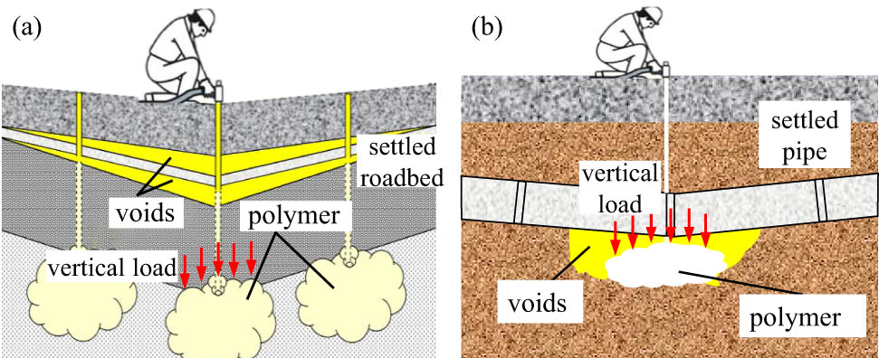
Representative applications of the TFPU grouting materials in civil engineering: (a) roadbed rehabilitation and (b) pipeline voids repairing.
The constitutive model of TFPU grouting material is the most important theoretical basis for evaluating its mechanical behavior under compression, which, however, is not fully understood yet. Previous studies have pointed out that the stress–strain curves of TFPU grouting material and polyurethane foams are similar in shape [7,8,23,24], indicating the similar mechanical behavior under uniaxial compression; therefore, the constitutive models of polyurethane foams can be used to study the mechanical properties of TFPU grouting materials. The constitutive models of polyurethane foams, such as the Gibson–Ashby equation [25], Gent-Thomas model [26], Kontou model [27], and Keivan model [28], require the full understanding of the micromorphology characteristics, which is difficult to achieve. The scanning electron microscope (SEM) observation results of the microstructure of polyurethane only contain the local information that may be less representative [7,8]. The phenomenological constitutive models that focus on reflecting the stress–strain curves of polyurethane foams with mathematical equations have also been proposed [22,29,30]. For example, the function represented by the series or parallel connections of a group of springs and dampers has been proposed to describe the stress–strain curves of polyurethane foams [22]. The equation forms of the constitutive models of polyurethane foams are often complicated and they contain undetermined parameters that can only be specified according to the experimental results [26,30]. It is impossible to directly use these constitutive models to evaluate the compressive strength of the practically used TFPU grouting materials.
The statistical damage constitutive model is another typical constitutive model for civil engineering materials [31,32,33,34,35]. Based on the damage mechanics theory, the failure of the material is caused by the failure of micro-units that make up it, and the amount proportion of the failed micro-units is defined as damage [33,36]. Assuming that the probability density function of the strength of the micro-units conforms to the Weibull function form, the equation reflecting the variation laws of damage with strain can be obtained, followed by the derivation of the statistical damage constitutive model [33]. After assigning the unknown parameters in the statistical damage model, the theoretical stress–strain curves that are in good agreement with the experimental ones can be obtained [33]. Previous researchers have proposed the statistical damage constitutive models of rock [31,32,35], concrete [33,34], and soil-concrete contact interface [37], and authors have also established a statistical damage constitutive model for TFPU grouting materials [8]. However, it was found that the statistical damage constitutive model of TFPU grouting material cannot describe the stress–strain curve after yield [8], indicating that the damage evolution equation proposed based on the Weibull distribution hypothesis cannot reflect the damaging process of TFPU grouting material.
In this study, the TFPU samples with different densities were prepared for conducting the uniaxial compression experiment. Based on the experimentally obtained stress–strain curves, the damage evolution equation of the TFPU samples was obtained through the function fitting way rather than using the Weibull distribution hypothesis, followed by the establishment of the statistical damage constitutive model. The statistical damage constitutive model was further simplified to a universal function with the density as the only independent variable. With the established constitutive model, the mechanical behavior of the TFPU grouting material can be predicted well according to the density only, which is acceptable for practical engineering. Studies here provide a new perspective to establish the constitutive models for not only TFPU grouting material but also other engineering materials.
2 Experimental study
2.1 Raw materials and sample preparation
The main raw materials for preparing TFPU samples are commercially available isocyanate and polyol. The material properties of isocyanate and polyol are shown in Table 1. When preparing the samples, the mass ratio of isocyanate to polyol was designed as 1:1.
The material properties of isocyanates and polyols
| Properties | Materials | |
|---|---|---|
| Isocyanates | Polyols | |
| Appearance | Brown liquid | Transparent liquid |
| Viscosity (mPa·s) | 150–250 | 200–400 |
| Density (g·cm−3) | 1.22–1.25 | 1.04–1.06 |
| –NCO (%) | 30.5–32.0 | — |
| APHA | — | <50 |
| Acidity (%) | <0.03 | — |
| pH | — | 5–7 |
| Hydrolyzed chlorine (%) | <0.2 | — |
| Hydroxyl value (mgKOH·g−1) | — | 325–345 |
The chemical reaction between the isocyanate and polyol occurs so fast that it is impossible to mix them fully with the conventional mechanical stirring method [38]. Herein the high-pressure airflow grouting method was used to fabricate the TFPU samples (as shown in Figure 2) [7,39]. With this method, the raw materials would be atomized into micro drops with the significantly increased specific surface areas, and thus mixed together fully [40]. The injection time of the two raw materials lasted for 10–40 s for fabricating the TFPU samples with different densities (about 0.10–0.54 g·cm−3) [7]. The high-pressure airflow grouting equipment for preparing the TFPU samples is developed by our research group and it has been widely used in practical engineering. The mixing ratio and air pressure have been preset by controlling the grouting equipment. The raw materials, their mixing ratio, and the high-pressure airflow grouting equipment are identical to those used in the practical grouting projects [4,6,16,17]. The previous field inspection results of the polymer grouting effect indicate that the two raw materials can completely react when using this mixing ratio and grouting method [6].

The preparation and curing processes of the TFPU samples.
The samples were cured in the environment at a temperature of 20°C and humidity of 40% for 24 h before remolding, and then, the dense layer on the surfaces of the samples was removed by polishing to minimize the influence of the dense layer on the testing results and improve the flatness of the end faces.
2.2 Experimental process
After having removed the surface dense layer, the real density of each sample was tested and then the micromorphology was characterized using a field emission SEM system, followed by the X-ray diffraction (XRD) and Fourier transform infrared (FTIR) characterizations. The uniaxial compression experiment was conducted using an electro-hydraulic servo universal testing system. The strain control loading method was used to apply load and the strain rate was 0.3 mm·min−1 to simulate the static loading [7]. Before load, some lubricant was used to reduce the surface friction between the TFPU sample and the test machine.
2.3 Experimental results
The SEM images of the microscopic morphology of TFPU samples with different densities are shown in Figure 3. It can be seen that at the microscopic scale, TFPU grouting materials are porous mediums made of a large number of closed micro-foams, and the shape of the section of the micro-foams is round or oval. The average equivalent diameter of the micro-foams in these TFPU grouting materials is in the range of 60–110 μm, and it declines gradually with the increasing density. More discussions about the microstructure characteristics of the micro-foams are included in the authors’ previous study [7].
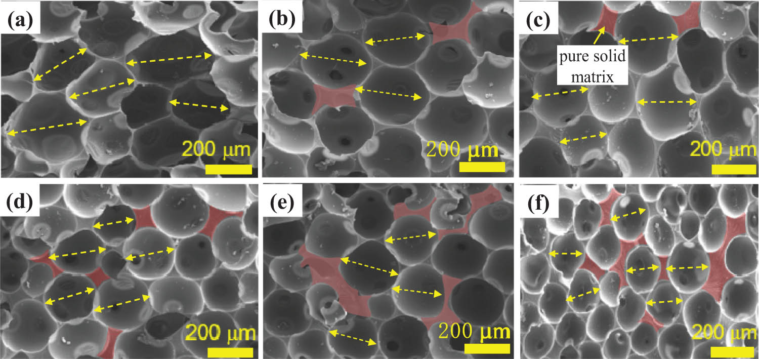
The micromorphology of the TFPU grouting materials with a density of: (a) 0.15, (b) 0.21, (c) 0.24, (d) 0.38, (e) 0.40, and (f) 0.46 g·cm−3.
From Figure 3, it can also be seen that with the increasing density, the volume of the pure solid matrix between neighboring micro-foams (highlighted in red) increases gradually. As the density increases to 0.46 g·cm−3, the solid matrix can even separate more than four micro-foams. For the TFPU grouting materials with a relatively lower density, the micro-foams undergo a lower surface tension so that they can expand to a larger size, and the micro-foams squeeze to each other to reduce the total surface energy as minimum as possible [41]. Along with the increased density, the amount of the generated pure polyurethane per unit volume increases, and thus the limitation on the free expansion of micro-foams is enhanced, which can reduce the squeezing interaction between them [7,41]. Therefore, more pure polyurethane is retained.
Figure 4(a) shows the XRD patterns of the TFPU grouting material. The powder diffractograms exhibit broad peaks at 2θ angles of about 8°, 11°, and 19°, indicating some degree of crystallinity. The intense peaks at 2θ of 11° and 19° represent the crystallinity characteristic of typical polyurethane with 1:1 mass ratio of polyol and isocyanate. These peaks are assigned to the scattering from TFPU chains with regular interplanar spacing [42]. Figure 4(b) is the IR spectrum of TFPU grouting material. It can be seen that the absorption peak of –NCO group almost disappears at 2,279 cm−1 and the peaks representing –NH, C–H, and –C═O stretching vibration exist, indicating the formation of carbamate. Besides, the presence of absorption peaks at 3,300, 3,120, and 1,600 cm−1 indicates that the TFPU contains benzene ring, the peak at 500 cm−1 is the characteristic peak of MDI, and the peak near 1,110 cm−1 is the stretching vibration peak of ether bond [43].

(a) XRD patterns and (b) Infrared spectrum of the TFPU.
Stress–strain curves can reflect the mechanical behavior of the tested materials [44]. Figure 5 shows the representative stress–strain curves of the tested TFPU samples with two different densities (0.21 and 0.40 g·cm−3), and the stress–strain curves of the TFPU samples with other different densities are included in Figure S1.

The representative stress–strain curves of the TFPU grouting materials with two different densities: (a) 0.2 ± 0.03 g·cm−3 and (b) 0.4 ± 0.03 g·cm−3. The stress and strain defined are nominal stress and engineering strain, respectively.
From Figure 5 and Figure S1, it can be found that the stress–strain curves contain five different stages regardless of the density, implying that varied density brings little influence on the variation laws of stress with strain. For the polymer grouting materials, due to the collapsing of the originally existing cracks and opening foams under compression, there exists initial compression stage (Stage I) on the stress–strain curves [44]. Afterwards, the axial stress increases almost linearly with the increasing strain (Stage II), followed by the yielding stage (Stage III). When having reached the yield strength, as the strain further increases, the axial stress will remain almost constant, which is known as the yield plateau stage (Stage IV). After the yield plateau stage, with the further increase in the strain, the axial stress starts to increase again. This stage is defined as the strain hardening stage (Stage V) [45,46]. Under uniaxial compression, the TFPU grouting materials usually undergo the strain hardening [7,8], and it is thought to be due to the compaction of the samples.
Figure 5 and Figure S1 show that the stress–strain curves of the TFPU samples are similar to those of the hyperelastic materials [47], but TFPU grouting material cannot be classified as the hyperelastic materials. Previous studies on the mechanical behavior of TFPU grouting material under cyclic loading have pointed out that even in the elastic stage, the unloading curve does not coincide with the loading curve, and that the deformation cannot be completely restored after unloading, and that the average elastic modulus declines with the number of the cycles [21]. Researchers have claimed that TFPU grouting material performs with both viscoelastic and viscoplastic properties [20,21]. In the author’s another study [7], it was found that the yielding and failure of the TFPU samples are not only caused by the compression deformation of micro-foams but also by cracks propagation.
Figure 5 and Figure S1 also show that with the increasing density, the yield strength of the TFPU samples increase gradually. This is because the mechanical properties of TFPU grouting materials are mainly affected by the mechanical behavior of the micro-foams [25,48]. When the density increases, the average diameter of the micro-foams declines, and the average thickness of walls of micro-foams increases (as shown in Figure 3), which indicates the stronger adsorption interactions between the atomic chains [49] and the enhanced stiffness [48], and thus the average strength of the micro-foams is enhanced. With the same amount of deformation, the strain energy accumulated in the TFPU grouting materials of relatively higher density will increase, the main reason for the enhanced mechanical properties [3]. In addition, Figure 5 and Figure S1 also show that the stress–strain curves of TFPU samples with a relatively lower density are smooth, but those of the samples with a higher density contain the stress declining that is caused by the coalescence and penetration of cracks. This indicates that the brittleness of the TFPU grouting materials increases with the increase in the density. However, compared with rock or concrete [3,36], the brittleness of the TFPU grouting materials is negligible.
3 Establishment of the statistical damage constitutive model
At present, both the anisotropic damage model [50,51] and the isotropic damage model [33,36] have been proposed to study the damage issue of solid materials. For the anisotropic damage model that describes the damaging process of solid materials containing the unevenly distributed micro-cracks, the propagation direction of micro-cracks should be considered, and thus the damage variables are defined as tensors. Researchers have claimed that with the anisotropic damage model, the damaging characteristics of solid materials such as metals and alloy materials can be well described [52,53,54]. For the multiphase materials, such as concrete, rock, and soil, the distribution of micro-cracks is much more disordered and the propagation direction of micro-cracks is hard to predict. Therefore, it is often assumed that the damage is isotropic, that is, the distribution characteristics of the micro-cracks are assumed to conform to the statistical distribution law [33,36]. TFPU samples are foamed porous material and the damaging process depends on the size and shape of the numerous micro-foams [20]. It has been found that the size and shape characteristics of the micro-foams can be described with the statistical distribution theory [7]. Therefore, the isotropic damage model is used in this study. The damage mechanics theory has pointed out that the failure of material is caused by the failure of micro-units that the material is made up of. The damaged micro-units will lose their bearing capacity gradually and the external load is mainly sustained by the remaining unfailed ones. From this perspective, the schematic diagram of the equivalent axial stress of the TFPU grouting material under the external load can be simplified as in Figure 6.
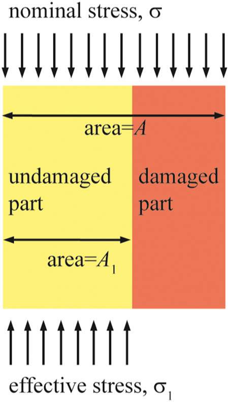
The schematic diagram of the axial stress of TFPU grouting material under compression.
For the TFPU samples under uniaxial compression, according to the Lemaitre strain equivalence hypothesis [55], the mathematical relationship between the nominal stress (σ) and effective stress (σ 1) can be represented as the following:
where A and A 1 represent the cross-sectional area of the entire and the undamaged part of the samples, respectively.
Here E is defined as the elastic modulus of TFPU, that is, the slope of the stress–strain curve at the linear elastic stage, and E 1 is defined as the ratio of stress to strain at any point of the stress–strain curves. It can be seen from Figures 5 and S1 that in the linear elastic stage, E 1 and E have almost the same value, and after yielding, E 1 will be lower than E. If the undamaged part is taken as the research individual, Hooke’s law is always valid, namely:
where
Under uniaxial compression, the two principal stresses perpendicular to the loading direction are equal to 0, which makes the second and third invariants of the stress tensor equal to 0, and thus, equation (2) can be simplified as the following [56]:
According to the Lemaitre strain equivalence hypothesis [55], the strain caused by nominal stress on damaged materials is equivalent to that caused by effective stress on nondestructive materials:
According to the damage mechanics, here the damage variable (D) can be defined as follows:
By substituting equations (4) and (5) in equation (3), the following equation can be obtained:
Previous studies on the statistical damage constitutive models for rock, concrete, and contact surfaces assume that the probability density of the strength of the micro-units follows the Weibull distribution function [31,32,33,34], based on which the damage equation can be obtained by integration, and then the equations describing the stress–strain curves of the materials can be obtained according to equation (6). Here the damage evolution equation of the TFPU grouting materials was obtained using a different method.
According to equation (6), D of the TFPU grouting materials with different densities can be represented with the following equation:
Equation (7) implies that D of the TFPU samples during the whole compression process can be directly calculated according to the stress–strain curves. Figure 7 shows the variation laws of the calculated D of TFPU samples with different densities (0.21 and 0.40 g·cm−3) with axial strain. The calculation results of D of other tested TFPU samples are included in Figure S2. When D was calculated, E was defined as the slope of the linear elastic stage (Stage II) of the stress–strain curves.

The variation laws of damage (D) of the TFPU grouting materials with different densities with strain under uniaxial compression: (a) 0.21 g·cm−3, and (b) 0.40 g·cm−3. The magenta circles and dots represent the calculated D, and the blue dotted lines represent the fitting results.
As can be seen from Figure 7, when the strain of the tested samples is small, the variation in D calculated from the stress–strain curves is disordered (represented by the magenta circles), and even show a decreasing trend. This is not consistent with the fact that the damage of the materials under load should be increasing. By comparing Figures 5 and 7, it can be noticed that the irregular variation stage of D corresponds to the initial compression stage of the stress–strain curves. The initial compression stage is caused by the collapse of the opening foams or the closure of the original cracks rather than the damage of the micro-units [44], which is equivalent to improving the compactness of the samples. Besides, the mechanical behavior of the samples in initial compression stage does not satisfy the Lemaitre strain equivalence hypothesis and Hooke’s law hypothesis. Therefore, in this stage, the calculated D is not correct. In order to describe the evolution laws of D using mathematical equations, the irregular variation stage of D was ignored in the following discussion. This is acceptable because the axial strain at the end of the initial compression stage is small (less than about 0.03, Figure 5 and Figure S1).
Figure 7 shows that after the initial compression stage, D varies continuously and regularly. With the increasing strain, D increases gradually from about 0, indicating the continuously accumulated damage in the samples [8], and then remains almost unchanged after reaching a certain value. The plateau phase of the damage-strain curves corresponds to the yield plateau stage (Stage VI) and strain hardening stage (Stage V) of the stress–strain curves. The plateau phase of the damage-strain curves indicates that when the yield strength has been reached, even if strain hardening occurs, no further damage or rupture surface is formed in the TFPU grouting materials. Figure 7 and Figure S2 also show that at the plateau stage of the damage-strain curves, D of different TFPU samples are different, and they are with the values of 0.81–0.94. This indicates that more than 80% of the micro-units have been damaged. Although D did not reach 1.0, most of the micro-units in the materials have been damaged. The above analysis results are consistent with the stress–strain curve presented in Figure 5.
Figure 7 and Figure S2 also show that the variation laws of the damage with strain conform to the form of first-order decay exponential function multiplied by a negative parameter [57], and the specific form is shown in equation (8). This function was adopted because it has the same form as the one obtained based on the assumption that the probability density of the strength of the micro-units of the TFPU grouting materials follows the two-parameter Weibull function [8]. As can be seen from Figure 7, when D was fitted by equation (8) (represented by the blue dotted lines), the goodness of fit (R 2) was close to 1.0, indicating the feasibility of using equation (8) to describe the variation laws of damage of the TFPU samples. Based on the fitting function presented in Figure 7, one can also see that for these two samples, when the theoretical D is equal to 0, the corresponding axial strain is about 0.018 and 0.033, respectively. The axial strain is close to 0 when the theoretical D is 0. From this perspective, it can be considered that the damage in the TFPU samples starts to increase from the beginning of the compression.
Currently, both the deterministic optimization method and uncertain optimization method have been used in correcting the undetermined parameters. Bayesian Statistics is a kind of uncertain optimization method for building a probabilistic characterization of the calibration process by using the Markov Chain Monte Carlo theory, and it has been widely used in the reliability analysis and evaluation of materials’ performance [58,59]. Besides, the deterministic optimization method that aims to obtain the best matching between model prediction data and measured one has also been used in the parameter corrections. Here based on the stress–strain curves, the values of the parameter a, parameter b, and parameter c in equation (8) were specified through function fitting with the least square method, one of the most commonly used deterministic optimization method because it simplifies the process of parameter correction. The values of these three parameters are included in Table S1. Substituting equation (8) in equation (6) provides the damage constitutive model of TFPU grouting materials. Because the assumptions of the statistical strength theory are involved in the definition of D, the damage constitutive model is called the statistical damage constitutive model. The statistical damage constitutive model of the polymer grouting materials can be represented as equation (9).
4 Discussions
The feasibility of the statistical damage constitutive models established here should be illustrated. Figure 7 shows the experimental stress–strain curves and the theoretical ones drawn according to equation (9) of TFPU grouting materials with different densities.
From Figure 8 and Figure S3, it can be seen that for the TFPU grouting materials, equation (9) can well describe the variation laws of the axial stress with the strain. The theoretical stress–strain curves drawn based on equation (9) are in good agreement with the experimental ones. The theoretical stress–strain curves obtained by equation (9) mainly contain the stress growth stage, stress plateau stage, and strain hardening stage. No initial compression stage can be observed on the theoretical stress–strain curves, and the difference between the theoretical axial stress and experimental ones in the strain hardening stage is large, but equation (9) is of significance for practical polymer grouting projects. This is because, in practical engineering, the large deformation of the TFPU grouting materials can result in the failure of the reinforced infrastructures [4,6,11]; therefore, the strain-hardening behavior of the TFPU grouting materials is negligible when discussing their strength performance. Equation (9) is applicable to describe the variation laws of the stress of the TFPU grouting materials before the strain-hardening stage. When the theoretical axial stress reaches the yield strength, the corresponding strain is almost equal to the experimental value, and the relative differences between the theoretical yield strength and the experimental one are lower than about 2%. From this perspective, the statistical damage constitutive models established here are reasonable and feasible.

The experimental and theoretical stress–strain curves of the TFPU grouting materials with different densities: (a) 0.15 g·cm−3, (b) 0.21 g·cm−3, (c) 0.38 g·cm−3, and (d) 0.40 g·cm−3. The theoretical ones were drawn according to equation (9).
As a comparison, the theoretical stress–strain curves obtained according to the Gibson model [25] and Avalle model [29], the two representative constitutive models for polyurethane materials, were also drawn in Figure 9. The equation forms of the Gibson model and Avalle model are shown in equations (10) and (11), respectively. The Levenberg–Marquadt optimization algorithm method was used to iterate to convergence to identify the optimal values of the undetermined parameters in the Gibson model and Avalle model (as shown in Tables S2 and S3, respectively).

From Figure 9, it can be found that as a piecewise function, Gibson model does reflect the stress increasing stage, stress plateau stage, and strain-hardening stage of the stress–strain curves of the TFPU grouting materials, but with poor accuracy, especially in the yield plateau stage. There is a large deviation between the experimental stress–strain curves and the ones obtained according to Gibson model. For these two representative TFPU samples, the maximum relative differences between the theoretical and experimental stress in the yield plateau stage are around 26.1 and 15.2%, respectively. The Avalle model is more accurate than the Gibson model and equation (9) in reflecting the mechanical behavior of the polymer grouting materials under compression. It can be seen that the stress–strain curves drawn according to Avalle model are almost identical with the experiment ones in all stages. Although the Avalle model has a higher accuracy, equation (9) has stronger applicability. This is because the equation form of the Avalle model is more complicated and the undetermined parameters have no clear physical meaning, whereas the parameter a and parameter b in equation (9) reflect the homogeneity and brittleness of the polymer grouting materials, respectively [8]. On the other hand, the values of the unknown parameters in the Avalle model vary irregularly with the density (as shown in Table S2), whereas the variation laws of parameter a, parameter b, and parameter c with the density can be easily described using the mathematical functions (as shown in Figure 10); therefore, it is possible to simplify the statistical damage constitutive model as a function with density as argument.

The variation laws of the undetermined parameters: (a) a, (b) b, and (c) c, in equation (9) with density.
As shown in Figure 10, for the TFPU grouting materials with the density range of 0.11–0.53 g·cm−3, with the increasing density, the parameter a and parameter c varies within the range of −1.196 to −1.045 and from 0.802 to 0.921, respectively, and the parameter b increases linearly from 0.074 to 0.120. Parameter a and parameter c can be simply considered as constants with the values of −1.13 and 0.863, respectively, and the variation in parameter b can be represented by equation (12).
As for the parameter E in equation (9), its variation laws with the density can be represented by power function [7], as shown in Figure 11. The function obtained by fitting is shown in equation (13)
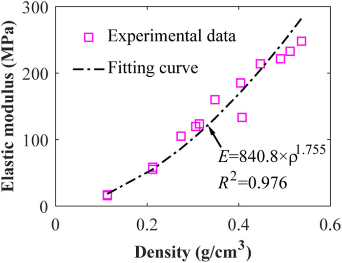
The variation laws of the elastic modulus (E) of TFPU grouting materials with density.
To this point, the statistical damage constitutive model can be written as a function with the density as the argument, as shown in equation (14).
Equation (14) shows that for the polymer grouting material used in practical engineering with the definite density, the theoretical stress–strain curve under uniaxial compression can be obtained without knowing any other information, which is of great significance for evaluating its mechanical behavior.
Figure 12 and Figure S4 present the comparison between the experimental stress–strain curves of TFPU grouting materials with the theoretical ones drawn according to equation (14). The experimental data presented in Figure 12(c) and (d) were not used in the function fitting of equations (12) and (13), and they are only used for comparison. From Figure 12, it can be seen that although there exist differences between the experimental stress–strain curves and the theoretical stress–strain curves, the simplified statistical damage constitutive model (equation [14]) can reflect the variation laws of axial stress of the polymer grouting materials, especially those before the strain hardening. For these four representative TFPU samples, the relative difference between the theoretical yield strain and the experimentally tested one is about lower than 5%, and the relative difference between the theoretical yield strength and the experimental yield strength is about 0.9–8.1%. Because the lattice distortion in strain hardening stage and anisotropy of TFPU were not considered in the establishment of the model, the deviation between the theoretical curve and the experimental curve is within an allowable range. However, with this simplified statistical damage constitutive model, the mechanical properties of the TFPU grouting material used in practical engineering can be easily predicated and evaluated based on the density, which is more convenient for engineering applications.
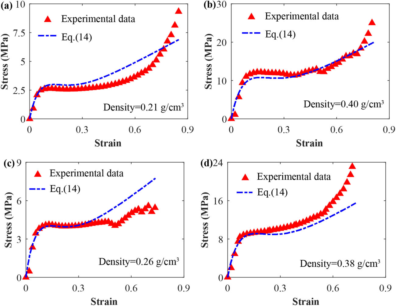
The comparison between the stress–strain curves of TFPU grouting materials obtained by equation (14) with the experimental ones. The densities of the TFPU grouting materials are: (a) 0.21 g·cm−3, (b) 0.40 g·cm−3, (c) 0.26 g·cm−3. and (d) 0.36 g·cm−3.
5 Conclusion
In this study, based on the uniaxial compression experiment results of the TFPU grouting materials, the damage evolution equation was obtained with the function fitting method, followed by the establishment of the statistical damage constitutive model. The applicability and feasibility of the established model was discussed. The conclusions are drawn as follows:
Under uniaxial compression, the stress–strain curves of the TFPU grouting materials with the density range of 0.11–0.53 g·cm−3 primarily contain the initial compression stage, linear elastic stage, yield stage, yield plateau stage, and the strain hardening stage. The varied density brings little influence on the variation laws of stress with strain.
According to the stress–strain curves and the damage evolution equation that was derived based on the Lemaitre strain equivalence hypothesis and linear elasticity hypothesis, the damage-strain curves of the TFPU grouting materials can be obtained. The damage-strain curves conform to the form of first-order decay exponential function, of which the specific form can be obtained by function fitting, and the goodness of fit is greater than 0.96.
The statistical damage constitutive model for TFPU grouting material can be established based on the damage evolution equation and it can be further simplified to a universal function with the density as the argument. The corresponding theoretical stress–strain curves are in good agreement with the experimental ones. This model can reflect the mechanical behavior of TFPU grouting material well. With this constitutive model, the mechanical properties of the TFPU grouting materials adopted in practical engineering can be directly obtained according to their designed density alone, which is more convenient and easier for engineering applications.
Acknowledgment
The authors are grateful for the finical support from National Natural Science Foundation of China (Grant Nos. 51908515 and 51704279), Guangdong Innovative and Entrepreneurial Research Team Program (2016ZT06N340).
-
Funding information: National Natural Science Foundation of China (Grant Nos. 51908515 and 51704279), Guangdong Innovative and Entrepreneurial Research Team Program (2016ZT06N340).
-
Author contributions: Mingrui Du: methodology, funding acquisition, writing – review & editing. Zhenyang Wang: methodology, investigation, data curation, writing – original draft. Hongyuan Fang: funding acquisition, supervision. Manjun Li: investigation. Peng Zhao: investigation.
-
Conflict of interest: The authors declare that they have no known conflict of interest or personal relationships that could have appeared to influence the work reported in this article.
References
[1] Du, X., H. Fang, S. Wang, B. Xue, and F. Wang. Experimental and practical investigation of the sealing efficiency of cement grouting in tortuous fractures with flowing water. Tunnelling and Underground Space Technology, Vol. 108, 2021, id. 03693.10.1016/j.tust.2020.103693Search in Google Scholar
[2] Du, M. R., H. W. Jing, W. H. Duan, G. S. Han, and S. J. Chen. Methylcellulose stabilized multi-walled carbon nanotubes dispersion for sustainable cement composites. Construction and Building Materials, Vol. 146, 2017, pp. 76–85.10.1016/j.conbuildmat.2017.04.029Search in Google Scholar
[3] Du, M. R., S. J. Chen, W. H. Duan, W. Q. Chen, and H. W. Jing. Role of multi-walled carbon nanotubes as shear reinforcing nano-pins in quasi-brittle matrices. ACS Applied Nano Materials, Vol. 1, No. 4, 2018, pp. 1731–1740.10.1021/acsanm.8b00162Search in Google Scholar
[4] Fang, H. Y., B. Li, F. M. Wang, Y. K. Wang, and C. Cui. The mechanical behaviour of drainage pipeline under traffic load before and after polymer grouting trenchless repairing. Tunnelling and Underground Space Technology, Vol. 74, 2018, pp. 185–194.10.1016/j.tust.2018.01.018Search in Google Scholar
[5] Saleh, S., N. Z. M. Yunus, K. Ahmad, and N. Ali. Improving the strength of weak soil using polyurethane grouts: A review. Construction and Building Materials, Vol. 202, 2019, pp. 738–752.10.1016/j.conbuildmat.2019.01.048Search in Google Scholar
[6] Guo, C., C. Cui, and F. Wang. Case study on quick treatment of voids under airport pavement by polymer grouting. Journal of Materials in Civil Engineering, Vol. 32, No. 7, 2020, id. 05020006.10.1061/(ASCE)MT.1943-5533.0003228Search in Google Scholar
[7] Li, M., M. Du, F. Wang, B. Xue, C. Zhang, and H. Fang. Study on the mechanical properties of polyurethane (PU) grouting material of different geometric sizes under uniaxial compression. Construction and Building Materials, Vol. 259, 2020, id. 119797.10.1016/j.conbuildmat.2020.119797Search in Google Scholar
[8] Wang, Z., M. Du, H. Fang, C. Zhang, M. Li, and M. Shi. Influence of different corrosion environments on mechanical properties of a roadbed rehabilitation polyurethane grouting material under uniaxial compression. Construction and Building Materials, Vol. 301, 2021, id. 124092.10.1016/j.conbuildmat.2021.124092Search in Google Scholar
[9] Wang, F., M. Shi, H. Li, and Y. Zhong. Experimental study on the anti-permeability properties of polymer grouting materials. Advanced Materials Research, Vol. 284–286, 2011, pp. 1952–1955.10.4028/www.scientific.net/AMR.284-286.1952Search in Google Scholar
[10] Guo, C., X. Chu, and F. Wang. The feasibility of non-water reaction polymer grouting technology application in seepage prevention for tailings reservoirs. Water Supply, Vol. 18, No. 1, 2017, pp. 203–213.10.2166/ws.2017.096Search in Google Scholar
[11] Li, B., F. Wang, H. Fang, K. Yang, and Y. Ji. Experimental and numerical study on polymer grouting pretreatment technology in void and corroded concrete pipes. Tunnelling and Underground Space Technology, Vol. 3, 2021, id. 103842.10.1016/j.tust.2021.103842Search in Google Scholar
[12] Liang, J., S. Ma, and X. Du. Diffusion model of parallel plate crack grouting based on foaming expansion characteristics of polymer slurry. Mathematics, Vol. 9, No. 22, 2021, id. 9222907.10.3390/math9222907Search in Google Scholar
[13] Zhang, J. and Y. Sun. Experimental and mechanism study of a polymer foaming grouting material for reinforcing broken coal mass. Ksce Journal of Civil Engineering, Vol. 23, No. 1, 2019, pp. 346–355.10.1007/s12205-018-0780-5Search in Google Scholar
[14] Hao, M., X. Li, Y. Zhong, B. Zhang, and F. Wang. Experimental study of polyurethane grout diffusion in a water-bearing fracture. Journal of Materials in Civil Engineering, Vol. 33, No. 3, 2021, id. 04020485.10.1061/(ASCE)MT.1943-5533.0003612Search in Google Scholar
[15] Hao, M., F. Wang, X. Li, B. Zhang, and Y. Zhong. Numerical and experimental studies of diffusion law of grouting with expansible polymer. Journal of Materials in Civil Engineering, Vol. 30, No. 2, 2018, id. 04017290.10.1061/(ASCE)MT.1943-5533.0002130Search in Google Scholar
[16] Guo, C. C. and F. M. Wang. Mechanism study on the construction of ultra-thin antiseepage wall by polymer injection. Journal of Materials in Civil Engineering, Vol. 24, No. 9, 2012, pp. 1183–1192.10.1061/(ASCE)MT.1943-5533.0000497Search in Google Scholar
[17] Bian, X. C., Z. Cheng, F. M. Wang, J. Q. Jiang, and Y. M. Chen. Experimental study on dynamic performance and long-term durability of high-speed railway subgrade rehabilitated by polymer injection technology. Chinese Journal of Geotechnical Engineering, Vol. 36, No. 3, 2013, pp. 562–568.Search in Google Scholar
[18] Moraes, M. T. D., F. B. D. Luz, H. Debiasi, J. C. Franchini, and V. R. D. Silva. Soil load support capacity increases with time without soil mobilization as a result of age-hardening phenomenon. Soil and Tillage Research, Vol. 186, 2019, pp. 128–134.10.1016/j.still.2018.09.009Search in Google Scholar
[19] Gao, X., W. Huang, Y. Wei, and Y. H. Zhong. Experiment and modeling for compressive strength of poyurethane grout materials. Acta Materiae Compositae Sinica, Vol. 34, No. 2, 2017, pp. 438–445.Search in Google Scholar
[20] Gao, X., Y. Wei, F. Wang, and Y. Zhong. Fatigue resistant and microstructure evolution of polyurethane grout materials under uniaxial compression. Acta Materiae Compositae Sinica, Vol. 34, No. 3, 2017, pp. 550–556.Search in Google Scholar
[21] Lu, Z., T. Chang, and R. Xie. The compressed properties of polyurethane rigid (PUR) foam. Chinese Journal of Material Research, Vol. 5, 1994, pp. 452–456.Search in Google Scholar
[22] Kim, T. R., J. K. Shin, T. S. Goh, H. S. Kim, J. S. Lee, and C. S. Lee. Modeling of elasto-viscoplastic behavior for polyurethane foam under various strain rates and temperatures. Composite Structures, Vol. 180, 2017, pp. 685–695.10.1016/j.compstruct.2017.08.032Search in Google Scholar
[23] Buzzi, O., S. Fityus, Y. Sasaki, and S. Sloan. Structure and properties of expanding polyurethane foam in the context of foundation remediation in expansive soil. Mechanics of Materials, Vol. 40, No. 12, 2008, pp. 1012–1021.10.1016/j.mechmat.2008.07.002Search in Google Scholar
[24] Niedziela, D., I. E. Ireka, and K. Steiner. Computational analysis of nonuniform expansion in polyurethane foams. Polymers, Vol. 11, No. 1, 2019, id. 11010100.10.3390/polym11010100Search in Google Scholar PubMed PubMed Central
[25] Gibson, L. J., and M. F. Ashby. Cellular solids: structure and properties, Cambridge University Press, Cambridge, 1997.10.1017/CBO9781139878326Search in Google Scholar
[26] Srivastava, V., and R. Srivastava. On the polymeric foams: modeling and properties. Journal of Materials Science, Vol. 49, No. 7, 2014, pp. 2681–2692.10.1007/s10853-013-7974-5Search in Google Scholar
[27] Kontou, E., G. Spathis, and V. Kefalas. Statistical model for the compressive response of anisotropic polymeric and metallic foams. Journal of Materials Science, Vol. 47, No. 13, 2012, pp. 5326–5332.10.1007/s10853-012-6419-xSearch in Google Scholar
[28] Safari, K. H., J. Zamani, R. M. Guedes, and F. J. Ferreira. The effect of heat developed during high strain rate deformation on the constitutive modeling of amorphous polymers. Mechanics of Time-Dependent Materials, Vol. 20, No. 1, 2016, pp. 45–64.10.1007/s11043-015-9283-7Search in Google Scholar
[29] Avalle, M., G. Belingardi, and A. Ibba. Mechanical models of cellular solids: Parameters identification from experimental tests. International Journal of Impact Engineering, Vol. 34, No. 1, 2007, pp. 3–27.10.1016/j.ijimpeng.2006.06.012Search in Google Scholar
[30] Akio, Y., H. Keita, K. Hiroshi, and C. Xi. Characterization of the compressive deformation behavior with strain rate effect of low-density polymeric foams. Polymer Testing, Vol. 50, 2016, pp. 1–8.10.1016/j.polymertesting.2015.11.021Search in Google Scholar
[31] Huang, S., Q. Liu, A. Cheng, and Y. Liu. A statistical damage constitutive model under freeze-thaw and loading for rock and its engineering application. Cold Regions Science and Technology, Vol. 145, 2018, pp. 142–150.10.1016/j.coldregions.2017.10.015Search in Google Scholar
[32] Xiang, L., W. G. Cao, and Y. H. Su. A statistical damage constitutive model for softening behavior of rocks. Engineering Geology, Vol. 143–144, No. 8, 2012, pp. 1–17.10.1016/j.enggeo.2012.05.005Search in Google Scholar
[33] Yu, T. Statistical damage constitutive model of quasi-brittle materials. Journal of Aerospace Engineering, Vol. 22, No. 1, 2009, pp. 95–100.10.1061/(ASCE)0893-1321(2009)22:1(95)Search in Google Scholar
[34] Xin, Y., N. Liang, X. Liu, and Z. Zhong. A study of test and statistical damage constitutive model of multi-size polypropylene fiber concrete under impact load. International Journal of Damage Mechanics, Vol. 28, No. 6, 2018, id. 105678951880522.10.1177/1056789518805220Search in Google Scholar
[35] Chen, K., M. Tang, and Z. Guo. Comparative study on three-dimensional conventional and modified statistical damage constitutive models. Multiscale and Multidisciplinary Modeling, Experiments and Design, Vol. 2, No. 4, 2019, pp. 259–267.10.1007/s41939-019-00052-3Search in Google Scholar
[36] Li, X., K. Peng, J. Peng, and D. Hou. Effect of thermal damage on mechanical behavior of a fine-grained sandstone. Arabian Journal of Geosciences, Vol. 14, No. 13, 2021, id. 1212.10.1007/s12517-021-07607-0Search in Google Scholar
[37] Cao, X. and J. Li. A shear damage model of the interface between soil and sulfate-corroded concrete. Construction and Building Materials, Vol. 293, No. 6, 2021, id. 123450.10.1016/j.conbuildmat.2021.123450Search in Google Scholar
[38] Wang, F. M., C. C. Guo, and Y. Gao. Formation of a polymer thin wall using the level set method. International Journal of Geomechanics, Vol. 14, No. 5, 2014, id. 04014021.10.1061/(ASCE)GM.1943-5622.0000363Search in Google Scholar
[39] Li, X. and M. C. Soteriou. High fidelity simulation and analysis of liquid jet atomization in a gaseous crossflow at intermediate Weber numbers. Physics of Fluids, Vol. 28, No. 8, 2016, id. 082101.10.1063/1.4959290Search in Google Scholar
[40] Prakash, S. R., S. S. Jain, J. A. Lovett, B. N. Raghunandan, R. V. Ravikrishna, and G. Tomar. Direct numerical simulations of atomization of a liquid jet in a swirling gas crossflow. Atomization and Sprays, Vol. 29, No. 5, 2019, pp. 1–17.10.1615/AtomizSpr.2019031322Search in Google Scholar
[41] He, Y., H. Ding, L. Liu, and K. Shin. Computer simulation of 2D grain growth using a cellular automata model based on the lowest energy principle. Materials Science and Engineering: A, Vol. 429, No. 1, 2006, pp. 236–246.10.1016/j.msea.2006.05.070Search in Google Scholar
[42] Trovati, G., E. A. Sanches, S. C. Neto, Y. P. Mascarenhas, and G. O. Chierice. Characterization of polyurethane resins by FTIR, TGA, and XRD. Journal of Applied Polymer Science, Vol. 115, No. 1, 2010, pp. 263–268.10.1002/app.31096Search in Google Scholar
[43] Bruckman, V. J. and K. Wriessnig. Improved soil carbonate determination by FT-IR and X-ray analysis. Environmental Chemistry Letters, Vol. 11, No. 1, 2013, pp. 65–70.10.1007/s10311-012-0380-4Search in Google Scholar PubMed PubMed Central
[44] Sarva, S. S., D. Stephanie, C. B. Mary, and C. Weinong. Stress–strain behavior of a polyurea and a polyurethane from low to high strain rates. Polymer, Vol. 48, No. 8, 2007, pp. 2208–2213.10.1016/j.polymer.2007.02.058Search in Google Scholar
[45] Miao, Y., H. He, and Z. Li. Strain hardening behaviors and mechanisms of polyurethane under various strain rate loading. Polymer Engineering & Science, Vol. 60, 2020, pp. 1083–1092.10.1002/pen.25364Search in Google Scholar
[46] Hossain, D., M. A. Tschopp, D. K. Ward, J. L. Bouvard, P. Wang, and M. F. Horstemeyer. Molecular dynamics simulations of deformation mechanisms of amorphous polyethylene. Polymer, Vol. 51, No. 25, 2010, pp. 6071–6083.10.1016/j.polymer.2010.10.009Search in Google Scholar
[47] Zuo, H., Y. H. Chen, H. B. Bai, and H. Sun. The compression deformation mechanism of a metallic rubber. International Journal of Mechanics and Materials in Design, Vol. 2, No. 3, 2005, pp. 269–277.10.1007/s10999-006-9007-xSearch in Google Scholar
[48] Goods, S. H., C. L. Neuschwanger, C. C. Henderson, and D. M. Skala. Mechanical properties of CRETE, a polyurethane foam. Journal of Applied Polymer Science, Vol. 68, No. 7, 1998, pp. 1045–1055.10.1002/(SICI)1097-4628(19980516)68:7<1045::AID-APP2>3.0.CO;2-FSearch in Google Scholar
[49] Chen, S., J. Hu, Y. Liu, H. Liem, and Q. Meng. Effect of molecular weight on shape memory behavior in polyurethane films. Polymer International, Vol. 56, No. 9, 2010, pp. 1128–1134.10.1002/pi.2248Search in Google Scholar
[50] Glema, A., T. Lodygowski, P. Perzyna, and W. Sumelka. The numerical analysis of the intrinsic anisotropic microdamage evolution in the elasto-viscoplastic material model. International Journal of Damage Mechanics, Vol. 18, No. 18, 2010, pp. 205–231.10.1177/1056789508097543Search in Google Scholar
[51] Voyiadjis, G. Z., J. Ju, J. L. Chaboche. Damage mechanics in engineering materials. The Winter Annual Meeting of the American Society of Mechanical Engineers, New York, N.Y., 1998.Search in Google Scholar
[52] Sumelka, W., M. Nowak, A. A. Nassr, H. Al-Rifaie, M. Malendowski, T. Gajewski, et al. Dynamic failure of the aluminium plate under air-blast loading in the framework of the fractional viscoplasticity model - theory and validation. International Journal of Impact Engineering, Vol. 158, 2021, id. 104024.10.1016/j.ijimpeng.2021.104024Search in Google Scholar
[53] Voyiadjis, G. Z., R. Al-Rub, and A. N. Palazotto. Thermodynamic framework for coupling of non-local viscoplasticity and non-local anisotropic viscodamage for dynamic localization problems using gradient theory. International Journal of Plasticity, Vol. 20, No. 6, 2004, pp. 981–1038.10.1016/j.ijplas.2003.10.002Search in Google Scholar
[54] Al-Rub, R. K. A., D. W. Lee, K. A. Khan, and A. N. Palazotto. Effective anisotropic elastic and plastic yield properties of periodic foams derived from triply periodic Schoen’s I-WP minimal surface. Journal of Engineering Mechanics, Vol. 146, No. 5, 2020, id. 04020030.10.1061/(ASCE)EM.1943-7889.0001759Search in Google Scholar
[55] Shi, Z. M., J. T. Li, and Y. Zhao. Study on damage evolution and constitutive model of sandstone under the coupled effects of wetting-drying cycles and cyclic loading. Engineering Fracture Mechanics, Vol. 5, 2021, id. 107883.10.1016/j.engfracmech.2021.107883Search in Google Scholar
[56] Wang, B., F. Wang, and Q. Wang. Damage constitutive models of concrete under the coupling action of freeze–thaw cycles and load based on Lemaitre assumption. Construction & Building Materials, Vol. 173, 2018, pp. 332–341.10.1016/j.conbuildmat.2018.04.054Search in Google Scholar
[57] Kim, H., C. Paik, Y. Chung, and Y. J. Kim. Investigating the length of data collection period with respect to rate constant in the first-order decay model. Journal of Material Cycles & Waste Management, Vol. 19, No. 1, 2017, pp. 32–37.10.1007/s10163-015-0378-7Search in Google Scholar
[58] Birrell, M., R. Astroza, J. I. Restrepo, K. Loftizadeh, and F. Hernández. Bayesian inference for calibration and validation of uniaxial reinforcing steel models. Engineering Structures, Vol. 243, No. 1, 2021, id. 112386.10.1016/j.engstruct.2021.112386Search in Google Scholar
[59] Kabir, H. and M. M. Aghdam. A generalized 2D Bézier-based solution for stress analysis of notched epoxy resin plates reinforced with graphene nanoplatelets. Thin-Walled Structures, Vol. 169, 2021, id. 108484.10.1016/j.tws.2021.108484Search in Google Scholar
© 2022 Mingrui Du et al., published by De Gruyter
This work is licensed under the Creative Commons Attribution 4.0 International License.
Articles in the same Issue
- Review Articles
- State of the art, challenges, and emerging trends: Geopolymer composite reinforced by dispersed steel fibers
- A review on the properties of concrete reinforced with recycled steel fiber from waste tires
- Copper ternary oxides as photocathodes for solar-driven CO2 reduction
- Properties of fresh and hardened self-compacting concrete incorporating rice husk ash: A review
- Basic mechanical and fatigue properties of rubber materials and components for railway vehicles: A literature survey
- Research progress on durability of marine concrete under the combined action of Cl− erosion, carbonation, and dry–wet cycles
- Delivery systems in nanocosmeceuticals
- Study on the preparation process and sintering performance of doped nano-silver paste
- Analysis of the interactions between nonoxide reinforcements and Al–Si–Cu–Mg matrices
- Research Articles
- Study on the influence of structural form and parameters on vibration characteristics of typical ship structures
- Deterioration characteristics of recycled aggregate concrete subjected to coupling effect with salt and frost
- Novel approach to improve shale stability using super-amphiphobic nanoscale materials in water-based drilling fluids and its field application
- Research on the low-frequency multiline spectrum vibration control of offshore platforms
- Multiple wide band gaps in a convex-like holey phononic crystal strip
- Response analysis and optimization of the air spring with epistemic uncertainties
- Molecular dynamics of C–S–H production in graphene oxide environment
- Residual stress relief mechanisms of 2219 Al–Cu alloy by thermal stress relief method
- Characteristics and microstructures of the GFRP waste powder/GGBS-based geopolymer paste and concrete
- Development and performance evaluation of a novel environmentally friendly adsorbent for waste water-based drilling fluids
- Determination of shear stresses in the measurement area of a modified wood sample
- Influence of ettringite on the crack self-repairing of cement-based materials in a hydraulic environment
- Multiple load recognition and fatigue assessment on longitudinal stop of railway freight car
- Synthesis and characterization of nano-SiO2@octadecylbisimidazoline quaternary ammonium salt used as acidizing corrosion inhibitor
- Perforated steel for realizing extraordinary ductility under compression: Testing and finite element modeling
- The influence of oiled fiber, freeze-thawing cycle, and sulfate attack on strain hardening cement-based composites
- Perforated steel block of realizing large ductility under compression: Parametric study and stress–strain modeling
- Study on dynamic viscoelastic constitutive model of nonwater reacted polyurethane grouting materials based on DMA
- Mechanical behavior and mechanism investigation on the optimized and novel bio-inspired nonpneumatic composite tires
- Effect of cooling rate on the microstructure and thermal expansion properties of Al–Mn–Fe alloy
- Research on process optimization and rapid prediction method of thermal vibration stress relief for 2219 aluminum alloy rings
- Failure prevention of seafloor composite pipelines using enhanced strain-based design
- Deterioration of concrete under the coupling action of freeze–thaw cycles and salt solution erosion
- Creep rupture behavior of 2.25Cr1Mo0.25V steel and weld for hydrogenation reactors under different stress levels
- Statistical damage constitutive model for the two-component foaming polymer grouting material
- Nano-structural and nano-constraint behavior of mortar containing silica aggregates
- Influence of recycled clay brick aggregate on the mechanical properties of concrete
- Effect of LDH on the dissolution and adsorption behaviors of sulfate in Portland cement early hydration process
- Comparison of properties of colorless and transparent polyimide films using various diamine monomers
- Study in the parameter influence on underwater acoustic radiation characteristics of cylindrical shells
- Experimental study on basic mechanical properties of recycled steel fiber reinforced concrete
- Dynamic characteristic analysis of acoustic black hole in typical raft structure
- A semi-analytical method for dynamic analysis of a rectangular plate with general boundary conditions based on FSDT
- Research on modification of mechanical properties of recycled aggregate concrete by replacing sand with graphite tailings
- Dynamic response of Voronoi structures with gradient perpendicular to the impact direction
- Deposition mechanisms and characteristics of nano-modified multimodal Cr3C2–NiCr coatings sprayed by HVOF
- Effect of excitation type on vibration characteristics of typical ship grillage structure
- Study on the nanoscale mechanical properties of graphene oxide–enhanced shear resisting cement
- Experimental investigation on static compressive toughness of steel fiber rubber concrete
- Study on the stress field concentration at the tip of elliptical cracks
- Corrosion resistance of 6061-T6 aluminium alloy and its feasibility of near-surface reinforcements in concrete structure
- Effect of the synthesis method on the MnCo2O4 towards the photocatalytic production of H2
- Experimental study of the shear strength criterion of rock structural plane based on three-dimensional surface description
- Evaluation of wear and corrosion properties of FSWed aluminum alloy plates of AA2020-T4 with heat treatment under different aging periods
- Thermal–mechanical coupling deformation difference analysis for the flexspline of a harmonic drive
- Frost resistance of fiber-reinforced self-compacting recycled concrete
- High-temperature treated TiO2 modified with 3-aminopropyltriethoxysilane as photoactive nanomaterials
- Effect of nano Al2O3 particles on the mechanical and wear properties of Al/Al2O3 composites manufactured via ARB
- Co3O4 nanoparticles embedded in electrospun carbon nanofibers as free-standing nanocomposite electrodes as highly sensitive enzyme-free glucose biosensors
- Effect of freeze–thaw cycles on deformation properties of deep foundation pit supported by pile-anchor in Harbin
- Temperature-porosity-dependent elastic modulus model for metallic materials
- Effect of diffusion on interfacial properties of polyurethane-modified asphalt–aggregate using molecular dynamic simulation
- Experimental study on comprehensive improvement of shear strength and erosion resistance of yellow mud in Qiang Village
- A novel method for low-cost and rapid preparation of nanoporous phenolic aerogels and its performance regulation mechanism
- In situ bow reduction during sublimation growth of cubic silicon carbide
- Adhesion behaviour of 3D printed polyamide–carbon fibre composite filament
- An experimental investigation and machine learning-based prediction for seismic performance of steel tubular column filled with recycled aggregate concrete
- Effects of rare earth metals on microstructure, mechanical properties, and pitting corrosion of 27% Cr hyper duplex stainless steel
- Application research of acoustic black hole in floating raft vibration isolation system
- Multi-objective parametric optimization on the EDM machining of hybrid SiCp/Grp/aluminum nanocomposites using Non-dominating Sorting Genetic Algorithm (NSGA-II): Fabrication and microstructural characterizations
- Estimating of cutting force and surface roughness in turning of GFRP composites with different orientation angles using artificial neural network
- Displacement recovery and energy dissipation of crimped NiTi SMA fibers during cyclic pullout tests