A novel method for low-cost and rapid preparation of nanoporous phenolic aerogels and its performance regulation mechanism
-
Yijun Zhang
 ,
Yingluo Zhuang
,
Yingluo Zhuang

Abstract
The large-scale application of phenolic aerogel is limited by its complex and lengthy production process as well as its expensive cost. Herein a simultaneous drying-curing method for phenolic aerogels was designed based on the sol–gel process, and a series of phenolic aerogels with different hexamethylenetetramine (HMTA) contents were prepared. The material parameters such as microstructure, pore structure, mechanical properties, shrinkage, and density of the aerogel were characterized. The results show that compared with the conventional full-sealing method, the simultaneous drying-curing method shortens the preparation time of aerogels by nearly half and improves the safety of the preparation process. The prepared phenolic aerogels still maintain the nanoporous microscopic morphology. When the HMTA content is 1/6 of the phenolic mass, the linear shrinkage rates of the aerogels prepared by this method and the conventional full-sealing method are 9.8 and 9.4%, respectively. The densities are 0.25 and 0.22 g·cm−3, and the BET specific surface areas are 54.42 and 54.31 m2·g−1, and the compressive yield strengths are 1.76 and 1.16 MPa. At the same time, the thermal conductivity of the phenolic aerogels prepared by the simultaneous drying-curing method is less than 0.06 W·(m·K)–1 at room temperature. These results indicate that the properties of the aerogels prepared by the simultaneous drying-curing method are close to those prepared by the conventional method, which proves that this method has guiding significance for the large-scale, low-cost, and rapid production of nanoporous phenolic aerogels.
1 Introduction
As a nanoporous material, aerogel has excellent properties such as low density, high specific surface area, high porosity, and low thermal conductivity [1,2,3,4,5,6,7,8,9]. Among the aerogel materials, phenolic aerogels are widely used in thermal insulation, catalysis, adsorption, and other fields due to their unique advantages such as high carbon residue rate, good toughness, and low cost [10,11,12,13,14,15,16,17]. In the 1990s, phenolic aerogels were successfully prepared for the first time in the Pekala research group of the LLNL in the United States. The Pekala team used resorcinol and formaldehyde as raw materials to prepare phenolic organic aerogels and their degraded carbon aerogel by the sol–gel process [18,19]. However, in traditional preparation methods, phenolic aerogels are synthesized from small molecules of phenols and aldehydes, which means the preparation time is usually more than 7 days [20,21,22]. Furthermore, the nanoporous wet gel will generate enormous capillary pressure during the drying process, causing the aerogel to collapse and wrinkle shrinkage, so the wet gel needs to be processed by expensive supercritical drying [23,24,25]. The large-scale industrial production of phenolic aerogels has been severely limited due to the high cost and complex preparation process. In recent years, researchers have focused on how to reduce the cost of aerogel production while also simplifying the preparation process.
In 1997, Fischer et al. [26] obtained larger aerogel pores by adjusting the ratio of catalyst (sodium carbonate) for the first time, thereby realizing the ambient pressure drying of phenolic aerogels. Wu and Fu [27] found that proper network structure strength, larger particle size and pore size, and low surface tension are three key factors to reduce the collapse of the pore structure of aerogels during ambient pressure drying. Jia et al. [28] used novolac resin as raw material and ethanol as an organic solvent, and obtained a phenolic wet gel with larger pores by adjusting the amount of hexamethylenetetramine (HMTA) added, thereby reducing the drying capillary pressure and realizing the ambient pressure drying of the wet gel. Jin et al. [23], Cheng [29,30], Hong et al. [31] and Wang et al. [32] used ethylene glycol as the organic solvent to solidify the phenolic aerogel at a high temperature of 150–180°C to form a strong network structure, and used ethanol with a lower surface tension as a replacement solvent to replace ethylene glycol in the wet gel. The ambient pressure drying of the phenolic wet gel was realized. Shi et al. [33] prepared phenolic aerogels based on common commercial phenolic resins, which further reduced the preparation cost.
However, due to the long curing and drying time of phenolic aerogel, its preparation time is generally more than 5 days. Furthermore, in the existing method, the sol–gel process of the phenolic solution is carried out in a sealed hydrothermal kettle, which usually generates high pressure due to the violent evaporation of the organic solvent. This makes the preparation process risky. Therefore, in this study, the hydrothermal reactor was modified to reduce the sealing performance. The semi-sealed reactor realizes the simultaneous curing and solvent drying process, which improves the preparation efficiency and safety. At the same time, the mechanism of regulation of different HMTA contents on the properties of phenolic aerogels was systematically investigated.
2 Materials and methods
2.1 Materials
Thermoplastic commercial phenolic resin powder (brand BR2123F) was purchased from Henan Hengyuan New Materials Co. Ltd (Henan, China); HMTA was purchased from Henan Borun Foundry Materials Co. Ltd (Henan, China); anhydrous ethanol (analytical grade) was purchased from Sinopharm Chemical Reagent Co. Ltd (Shanghai, China).
2.2 Sample preparation
The ID of the phenolic aerogel samples prepared by different methods and with different HMTA contents is shown in Table 1.
The ID of the phenolic aerogel samples prepared by different methods and with different HMTA contents
| Sample ID | Preparation method | HMTA content |
|---|---|---|
| S1/8 | Simultaneous drying-curing | 1/8 |
| S1/7 | Simultaneous drying-curing | 1/7 |
| S1/6 | Simultaneous drying-curing | 1/6 |
| C1/8 | Conventional full-sealing | 1/8 |
| C1/7 | Conventional full-sealing | 1/7 |
| C1/6 | Conventional full-sealing | 1/6 |
2.2.1 Conventional full-sealing method
First, the thermoplastic phenolic resin powder was dissolved in absolute ethanol at 80°C to prepare a phenolic solution with a resin mass fraction of 20 wt%. 1/8, 1/7, and 1/6 HMTA of phenolic resin mass was dissolved in phenolic solution under 500 rpm magnetic stirring at 35°C. The prepared gel precursor solution was placed in a hydrothermal reactor equipped with a polytetrafluoroethylene lining, and the lid of the reactor was tightened to seal it. The reactor was placed in a blast drying oven, the gel was solidified at 80°C for 3 days, and cooled to room temperature to open the reactor. The phenolic wet gel was demolded and dried at ambient temperature and pressure for 2 days and at 45°C for 1 day to obtain phenolic dry gels with different HMTA contents.
2.2.2 Simultaneous drying-curing method
As shown in Figure 1, the hydrothermal reactor was modified to weaken its tightness. Remove the sealing steel ingot of the hydrothermal reactor, replace it with a sealing steel ring, and punch the PTFE sealing cover at the same time. The prepared gel precursor solutions with different HMTA contents were placed in the modified hydrothermal reactor, and the gel was solidified at 80°C for 3 days in a blast drying oven, then cooled to room temperature to open the kettle. The gel has been essentially dried at this point, and phenolic aerogels with varying HMTA contents can be obtained by demolding the gel and supplementary drying at 45°C for 4 h. Compared with the conventional all-sealing method, this method not only improves safety but also cuts the preparation time to half.
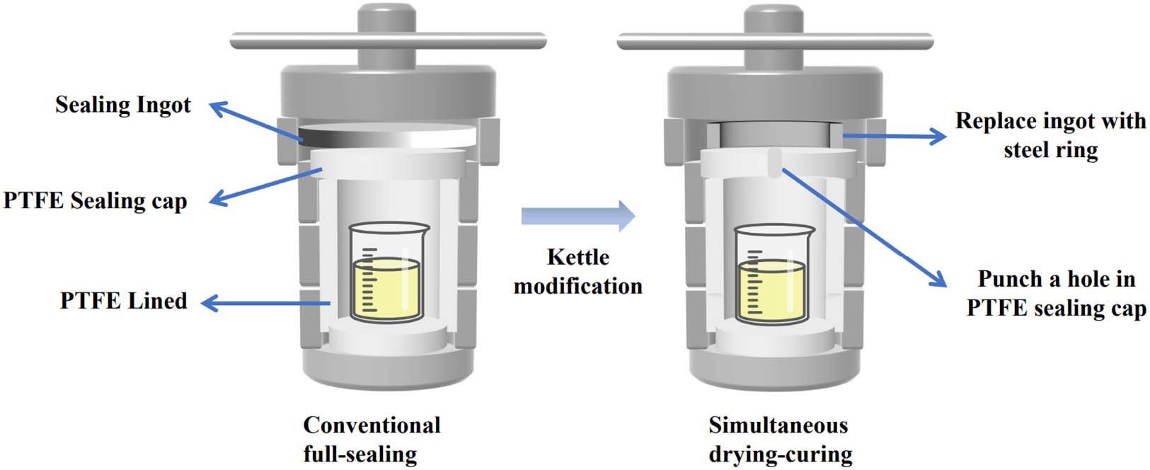
Schematic diagram of the modification of the hydrothermal reactor.
2.3 Performance testing and structural characterization
2.3.1 Micromorphology
Phenolic particles and pore structure were observed by a field emission scanning electron microscope (FESEM; Zeiss Ultra Plus manufactured by Carlzeiss, Germany, operating voltage of 5 kV). The observed samples must be dried at a high temperature of 180°C for 3 h to remove volatile small molecules, and then observed after spraying conductive adhesive.
2.3.2 Pore structure
The specific surface area and mesoporous pore parameters of phenolic aerogel were analyzed by a nitrogen adsorption–desorption test (Micromeritics ASAP2460 manufactured by Make, USA). At the same time, pore size statistics of pores larger than 100 nm in SEM photographs were used to determine the variation rule of the aerogel macropore. The specific surface area of the aerogel was calculated by the BET isotherm equation, which is shown in equation (1).
where V is the volume of adsorbed gas, m refers to the mass of the aerogel, V m refers to the saturated adsorption capacity of the monolayer, p 0 is the saturated vapor pressure of the adsorbed gas, and C is the BET equation constant.
2.3.3 Linear shrinkage
The shrinkage rate of the aerogel is calculated using equation (2) by measuring the inner diameter of the mold and the diameter of the xerogel, and the aerogel’s technological performance is evaluated.
where S l refers to the linear shrinkage rate, L d refers to the diameter of the dry gel, and L m refers to the inner diameter of the mold.
2.3.4 Density
The aerogel was processed into a cuboid of 10 mm × 10 mm × 20 mm, the mass of the cuboid was weighed, and the density of the aerogel was calculated according to equation (3).
where ρ is the density of the aerogel, m refers to the mass of the aerogel, v is the volume of the aerogel, and a, b, and h refer to the length, width, and height of the aerogel, respectively.
2.3.5 Mechanical properties and thermal conductivity
According to the GB/T 2567-2008 standard, the quasi-static compressive mechanical properties of the aerogel cuboids were tested, and the loading speed was 2 mm·min−1. The yield strength of the aerogel with pore collapse and pore wall breakage was used as a parameter to measure the mechanical properties of the aerogel.
A thermal constant analyzer (TPS2500S manufactured by Hot Disk, Sweden) was used to determine the thermal conductivity of aerogel at room temperature.
3 Results and discussion
3.1 Preparation efficiency of new method
In order to characterize the preparation efficiency and safety of the simultaneous drying-curing method, the preparation time and peak temperature during the preparation process reported in the relevant literature are statistics. It can be seen from Table 2 that the preparation time of the works of Yang et al. [22], Wu et al. [24], Jia et al. [28], Shi et al. [33], Li et al. [34], Sepehri et al. [35], Leonard et al. [36], Xiao et al. [37], Cheng et al. [38] and He et al. [39] is ranging approximately from 100 to 200h and the peak temperatures are varying from 80 to 150°C. At the same time, the simultaneous drying-curing method used in this work shortens the preparation time of phenolic aerogel to 76 h, and the peak temperature during the preparation process is only 80°C. This demonstrates that when compared to the conventional full-sealing method, the simultaneous drying-curing method can significantly improve the preparation efficiency and safety during the preparation process.
Comparison of the preparation time and peak temperature of the work including: Yang et al. [22], Wu et al. [24], Jia et al. [28], Shi et al. [33], Li et al. [34], Sepehri et al. [35], Leonard et al. [36], Xiao et al. [37], Cheng et al. [38] and He et al. [39] studied here
| Ref. | Preparation time (h) | Peak temperature (°C) |
|---|---|---|
| Li et al. | Above 200 | 80 |
| Sepehri et al. | Above 200 | 85 |
| Léonard et al. | Above 200 | 90 |
| Wu et al. | Above 170 | 80 |
| Xiao et al. | 144 | — |
| Yang et al. | Above 140 | 90 |
| Jia et al. | 136 | 80 |
| Cheng et al. | 120 | 180 |
| Shi et al. | 116 | 80 |
| He et al. | 98 | 150 |
| This work | 76 | 80 |
3.2 Key mechanism of simultaneous drying-curing
In order to analyze the formation mechanism of pores of different scales in aerogels, high-magnification SEM was used to observe the pore structure of aerogels. It can be found from Figure 2 that the pores of phenolic aerogels can be basically divided into two categories; one is macropores with a pore size in the range of 50 nm−1 µm, and the other is mesopores with a pore size in the range of 2–50 nm. Through the observation of the phenolic particles that constitute these two kinds of pores, it can be found that when the degree of crosslinking between the small phenolic particles is relatively large, a large area of bonding will be formed between a small number of phenolic particles, which will be easily stacked and bonded to form slit-like pores. These pores are generally mesopores; when the degree of cross-linking between large aggregation particles is low, a limited area of bonding forms between the large phenolic particles, causing them to overlap and create macropores. Due to their small pore size, these slit-like mesopores are prone to generating extremely high capillary pressure during drying, causing the aerogel to collapse [27]. Especially during the simultaneous drying process, the wet gel is subjected to high drying capillary pressure before obtaining a strong skeleton, causing it to collapse very easily. At the same time, many studies have shown that the existence of macropores can effectively reduce the collapse of aerogels [26,27]. As a result, increasing the macropore content of the aerogel is the key to achieving simultaneous drying-curing.

SEM local enlargement of aerogel pores.
The capillary pressure generated during the drying process of aerogels has a strong relationship with the pore size. The smaller the pore size of the aerogel, the greater the capillary pressure generated, and the easier it is for the pores of the aerogel to collapse [27]. According to numerous studies [22,25,33,39], the pore parameters of aerogels can be significantly regulated by adjusting the catalyst content. As a consequence, the feasibility of phenolic aerogels prepared by simultaneous drying-curing with different HMTA contents at the same time was investigated.
3.3 Micromorphology of phenolic aerogels
The SEM pictures of different phenolic aerogel samples are shown in Figure 3. It can be seen from Figure 3 that the phenolic aerogels prepared by the simultaneous drying-curing method and the conventional full-sealing method both maintain the microscopic morphology of abundant nanopores. At the same time, the SEM image shows that the phenolic particles are stacked and agglomerated with each other to form a “grape bunch”-like microstructure. The aerogel particle size increased significantly with the increase in HMTA content. In order to further characterize the change in aerogel particle size, Nano measurer was used to count the size of phenolic particles. The particle size distribution histograms of different aerogel samples are shown in Figure 4.

SEM images of different samples: (a) C1/8, which means phenolic aerogel with 1/8 HMTA content prepared by the conventional full-sealing method; (b) C1/7; (c) C1/6; (d) S1/8, which means phenolic aerogel with 1/8 HMTA content prepared by the simultaneous drying-curing method; (e) S1/7; and (f) S1/6.

Histogram of particle size distribution of different aerogel samples: (a) C1/8, which means phenolic aerogel with 1/8 HMTA content prepared by the conventional full-sealing method; (b) C1/7; (c) C1/6; (d) S1/8, which means phenolic aerogel with 1/8 HMTA content prepared by the simultaneous drying-curing method; (e) S1/7; and (f) S1/6.
It can be seen from Figure 4 that with the increase in HMTA content in the phenolic aerogel from 1/8 to 1/7 and 1/6, the average particle size of the aerogel prepared by the conventional full-sealing method continued to increase from 42.47 to 49.22 nm and 57.28 nm; the average particle size of the aerogels prepared by the simultaneous drying-curing method continued to increase from 42.35 nm to 49.43 and 59.25 nm. This is because the catalytic impact of increasing HMTA content enhances the surface activity of the sol particles while also acting as a curing agent to raise the degree of cross-linking between the nanogel particles. This results in the continuous accumulation and fusion of particles, and the particle size of the formed phenolic large particles also increases [33]. At the same time, the particle size distribution of phenolic particles appears to become more scattered as the HMTA content increases. This is caused by the different degree of cross-link stacking during the growth of phenolic particles with the increase in HMTA content.
Figure 4 shows that the average particle size of the phenolic aerogel prepared by the simultaneous drying-curing method and the conventional full-sealing method are nearly identical, indicating that the simultaneous drying process has no effect on the growth and cross-linking of the phenolic particles. This proves, that on the basis of improving production efficiency and safety, the phenolic aerogel produced by the simultaneous drying-curing method still maintains the microscopic morphology of stacked nanoparticles.
3.4 Pore structure of phenolic aerogels
The N2 adsorption–desorption test was used to further investigate the mesoporous structure of the aerogel. Figure 5 depicts the N2 adsorption–desorption curves of various phenolic aerogel samples. Figure 5 shows that the aerogel adsorption–desorption curves belong to the conventional IV isotherm and H3 loop, indicating that the mesoporous pore structure is a slit hole or a conical hole, according to the IUPAC classification standard. This is in agreement with the prior SEM photos at high magnification. The absence of an adsorption plateau in the adsorption–desorption isotherm indicates that some pores are not completely filled with nitrogen during the adsorption process, indicating that there are some macropores (>50 nm) in the aerogel that cannot be detected by nitrogen adsorption [40]. This also confirms the existence of macropores in the SEM images. At the same time, the nitrogen adsorption amount is more than zero in the low pressure area, which indicates that the aerogel retains a few micropores (<2 nm) [41].

N2 adsorption–desorption curves of different phenolic aerogel samples: (a) phenolic aerogels with different HMTA contents prepared by the conventional full-sealing method and (b) phenolic aerogels with different HMTA contents prepared by the simultaneous drying-curing method.
Under the same pressure, the nitrogen adsorption capacity of aerogel prepared by the simultaneous drying-curing method and the conventional full-sealing method both decrease continuously as the HMTA addition amount increases, implying that the specific surface area and pore content of the material may decrease. When comparing Figure 5(a) with Figure 5(b), it can be seen that the peak nitrogen adsorption amount of the phenolic aerogel prepared by the simultaneous drying-curing method is greater than that prepared by the conventional full-sealing method, implying that the aerogel prepared by the simultaneous drying-curing method has a higher macropore content and pore volume.
From the nitrogen adsorption–desorption curve of the aerogel, the average BJH pore size, BET specific surface area, and BJH pore volume were obtained. Simultaneously, the Nano measurer was used to perform pore size statistics on pores larger than 100 nm in SEM images of various aerogel samples to define the average pore size of the macropores in the aerogel. The BJH pore size, BET specific surface area, and BJH pore volume of the aerogel reduced as the HMTA content increased, as shown in Table 3. This is because the pores detected by nitrogen adsorption are primarily slit mesopores generated by the crosslinking and bonding of phenolic particles in the aerogel. The size of such mesopores is continuously decreased by the compression of phenolic particles as HMTA content increases. However, macropore statistical results demonstrate that the average pore size of macropores grows as HMTA content increases, which is exactly the opposite of the changing rule of mesoporous pores. This is because the pore-forming mechanism of macropores in phenolic aerogels is different from that of mesopores. Macropores are mainly formed by the overlapping of agglomerated large particles. The phenolic particles grew larger and more prone to particle agglomeration as the HMTA level increased, resulting in larger macropores formed by overlapping large agglomerated particles.
Pore parameters of different phenolic samples
| Sample ID | BJH Pore diameter (nm) | BET specific surface area (m2·g−1) | BJH pore volume (cm³·g−1) | SEM Average pore diameter (nm) |
|---|---|---|---|---|
| C1/8 | 16.3 | 98.15 | 0.38 | 122.74 |
| C1/7 | 16.1 | 81.77 | 0.31 | 128.72 |
| C1/6 | 14.9 | 54.31 | 0.19 | 130.59 |
| S1/8 | 19.6 | 88.95 | 0.41 | 118.13 |
| S1/7 | 21.6 | 66.06 | 0.34 | 125.85 |
| S1/6 | 17.4 | 54.42 | 0.21 | 150.85 |
By comparing the average pore size of the SEM photos of two different methods in Table 3, it is found that the average pore size of S1/8 macropores is smaller than that of C1/8, while the pore size of S1/6 is larger than that of C1/6. The reason is that with the increase in HMTA content, the macropore content also increased, and the capillary pressure caused by the intense evaporation of ethanol in the simultaneous drying-curing process compressed the small pores in the aerogel, so that the average pore size of S1/6 was larger than C1/6. However, most of the pores in the S1/8 sample have significant shrinkage due to the low content of macropores in the sample, so the average pore size of the macropores in S1/8 is smaller than that of C1/8.
According to the comparison of BET specific surface area and BJH pore volume of aerogel prepared by the simultaneous drying-curing method and the conventional full-sealing method in Table 3, the pore parameters of aerogel prepared by the simultaneous drying-curing method are closer to those of the conventional method as the HMTA content increases. As a result, raising the dose of HMTA can enhance the content of large-size pores, lower the capillary pressure induced by drying, and limit the collapse of nano-pores, allowing the drying and curing of phenolic aerogel to be synchronized.
3.5 Linear shrinkage of phenolic aerogels
The shrinkage rates before and after drying were used to measure the technological properties of different phenolic aerogels. The shrinkage rate histograms of different aerogel samples are shown in Figure 6. Figure 6 demonstrates that the shrinkage rate of the phenolic aerogel generally decreases as the HMTA content increases. This is because the phenolic particles grow in size as the HMTA content increases, increasing the macropore content of the aerogel. The presence of macropores reduces the capillary pressure during drying, thereby reducing drying shrinkage [27]. At the same time, it can be found that the shrinkage rate of the phenolic aerogel prepared by the simultaneous drying-curing method is higher than that of the conventional method. This is because the curing and drying processes occur simultaneously, the porous network structure of the aerogel is not completely cured and has to bear a large drying capillary pressure, resulting in significant shrinkage.

Histogram of the linear shrinkage of different phenolic aerogel samples.
However, the shrinkage difference between the phenolic aerogel generated by the simultaneous drying-curing method and the conventional method rapidly reduces as the HMTA content increases, as shown in Figure 6. The shrinkage difference is only 0.4% when the HMTA content is 1/6. This suggests that appropriately raising the HMTA concentration is more favorable to narrowing the performance gap between the simultaneous drying-curing method and the conventional method, which is consistent with the prior nitrogen adsorption test’s conclusion.
3.6 Density and mechanical properties of phenolic aerogels
Figure 7 shows the density and compressive yield strength histograms of various phenolic aerogel samples. The density of phenolic aerogel generated by simultaneous drying-curing method is higher than that of aerogel prepared by conventional method with the same HMTA content, as shown in Figure 7a and b, which is owing to the high shrinkage rate of phenolic aerogel prepared by this method. This is because the pore structure of the phenolic aerogel generated by simultaneous drying and curing bears a high capillary pressure when it is not fully cured and delicate. Figure 7 shows that when the amount of HMTA in the aerogel increased, the density of the aerogel decreased, which was in line with the changing rule of aerogel shrinkage with HMTA. At the same time, the fact that the density of the C1/7 sample (0.24 g·cm−3) is higher than that of C1/8 (0.19 g·cm−3) is consistent with the rule that C1/7 (13.1%) shrinks more than C1/8 (12.5%). These phenomena indicate that the density parameters of aerogel mainly depend on its shrinkage rate.

Histogram of the density and compressive yield strength of different phenolic aerogel samples: (a) phenolic aerogels with different HMTA contents prepared by the conventional full-sealing method and (b) phenolic aerogels with different HMTA contents prepared by the simultaneous drying-curing method.
Figure 7a and b shows that the phenolic aerogel prepared by the simultaneous drying-curing method has a greater yield strength than the phenolic aerogel prepared by the conventional process. The yield strength of the aerogel prepared by the simultaneous drying-curing method reaches 3.22 MPa when the HMTA content is 1/8, whereas the conventional method only has 0.76 MPa. At the same time, the variation law of aerogel yield strength and density is found to be quite consistent. These phenomena indicate that density is the most critical factor affecting the mechanical properties of the aerogel when the pore size of the aerogels is on the same nanometer scale.
The density and mechanical properties of aerogels show that the pore structure is still the most fundamental parameter for regulating the properties. By increasing the amount of HMTA, the macropore content increases, reducing capillary pressure during the drying process and decreasing the shrinkage rate of the aerogel. Aerogels with low shrinkage have a lower density, but their mechanical properties suffer as well.
3.7 Thermal conductivity of phenolic aerogels
Thermal conductivity at room temperature was used to characterize the thermal insulation ability of phenolic aerogels. Figure 8 depicts the thermal conductivity of various aerogel samples.

Thermal conductivity of various phenolic aerogel samples at room temperature.
Aerogel’s excellent thermal insulation ability is primarily due to its low density and abundance of nanopores. The aerogel’s nanoporous microstructure can significantly inhibit gas heat conduction, while its lower density can further reduce solid heat conduction. In general, the lower the density and average pore size of aerogels, the lower their thermal conductivity at room temperature [22,25,28]. Figure 8 shows that, with the exception of S1/8, the thermal conductivity of phenolic aerogel increases as the amount of HMTA increases. At the same time, Table 3 shows that as the amount of HMTA increases, the macropore content of the aerogel increases as well. The ability of phenolic aerogel to provide thermal insulation decreased as the amount of macropores increased. The thermal conductivity of S1/8 reaches 0.0521 W·(m·K)−1. This is due to its high density (0.33 g·cm−3), which is attributed to its high shrinkage (21.8%) during drying.
The phenolic aerogel prepared by the simultaneous drying-curing method has a higher thermal conductivity than the conventional full-sealing method. S1/7 and S1/6 have values of 0.0494 and 0.0504 W·(m·K)−1, respectively, whereas C1/7 and C1/6 have values of 0.0471 and 0.0483 W·(m·K)−1, respectively. This is due, once again, to the fact that the density of phenolic aerogel during simultaneous drying is higher than that of the conventional method. However, all the samples prepared by the simultaneous drying-curing method exhibit thermal conductivities that are less than 0.06 W·(m·K)−1, demonstrating that they have the potential for widespread industrial use in the field of thermal insulation.
4 Conclusion
In this work, a simultaneous drying-curing method of phenolic aerogel was designed based on the sol–gel route. The morphology, pore structure, shrinkage, density, and mechanical properties of aerogel were characterized, and the performance regulation mechanism of phenolic aerogel was investigated. A new theory of the pore formation mechanism of phenolic aerogel was also proposed. The conclusions are as follows:
Compared with the conventional full-sealing method, the new method not only reduces the preparation time by nearly 50% but also improves the safety of the preparation process by reducing the peak temperature and pressure during the gel. This method provides a low-cost, safe, and rapid way to prepare nanoporous phenolic aerogels.
The nanoporous microstructure of the phenolic aerogel prepared by the simultaneous drying-curing method is still present. The BJH average pore size reaches 19.3 nm, and the BET specific surface area reaches 88.95 m2·g−1 when the HMTA content is 1/8.
Mesopores originate from the slits formed by a small number of phenolic particles bonded and stacked, while macropores are formed by the overlapping of many large phenolic particles.
The performance gap between phenolic aerogels manufactured by the simultaneous drying-curing method and those made by the conventional method can be narrowed by increasing HMTA content. When the HMTA content is 1/6 of the phenolic mass, the density of the aerogel made by the simultaneous drying-curing method and the conventional method was 0.25 and 0.22 g·cm−3, and the BET specific surface area was 54.42 and 54.31 m2·g−1, respectively. The difference between the two linear shrinkage rates is only 0.4%. All the samples prepared by the simultaneous drying-curing method exhibit thermal conductivities that are less than 0.06 W·(m·K)−1, demonstrating that they have the potential for widespread industrial use in the field of thermal insulation.
Acknowledgments
This research was supported by the Fundamental Research Funds for the Central Universities, China (WUT: 2021III003XZ). We also would like to express our sincere gratitude to the editor David Hui and two anonymous reviewers for their valuable comments, which have greatly improved this paper.
-
Funding information: This research was supported by the Fundamental Research Funds for the Central Universities, China (WUT: 2021III003XZ)
-
Author contributions: Y-J.Z.: original draft and writing – review and editing. C-F.Y.: formal analysis and writing – review and editing. J.D.: formal analysis, funding acquisition, supervision, and writing. Y-L.Z.: supervision and writing – review and editing. Y.L.: supervision and writing – review and editing. C-K.W.: supervision, and writing – review and editing. Z-X.H.: formal analysis, funding acquisition, supervision, and writing – review and editing. All authors have read and agreed to the published version of the manuscript.
-
Conflict of interest: The authors declare that there are no conflicts of interest.
-
Data availability statement: Data available on request from the authors.
References
[1] Feng, C. and S. S. Yu. 3D printing of thermal insulating polyimide/cellulose nanocrystal composite aerogels with low dimensional shrinkage. Polymers, Vol. 13, 2021, id. 3614.10.3390/polym13213614Suche in Google Scholar PubMed PubMed Central
[2] Feng, J., S. T. Nguyen, Z. Fan, and H. Duong. Advanced fabrication and oil absorption properties of super-hydrophobic recycled cellulose aerogels. Chemical Engineering Journal, Vol. 270, 2015, pp. 168–175.10.1016/j.cej.2015.02.034Suche in Google Scholar
[3] Hu, P. L., Y. J. Sun, B. Z. Gao, M. Gong, B. Luo, and J. P. Fan. Novel monolithic yttria-alumina aerogel with low thermal conductivity made from inorganic precursors. Ceramics International, Vol. 48, 2022, pp. 18699–18703.10.1016/j.ceramint.2022.03.143Suche in Google Scholar
[4] Song, L. M., Y. Q. Chen, Q. C. Gao, Z. Li, X. Y. Zhang, H. L. Wang, et al. Low weight, low thermal conductivity, and highly efficient electromagnetic wave absorption of three-dimensional graphene/SiC-nanosheets aerogel. Composites Part A: Applied Science and Manufacturing, Vol. 158, 2022, id. 106980.10.1016/j.compositesa.2022.106980Suche in Google Scholar
[5] Tian, J., Y. Yang, T. T. Xue, G. J. Chao, W. Fan, and T. X. Liu. Highly flexible and compressible polyimide/silica aerogels with integrated double network for thermal insulation and fire-retardancy. Journal of Materials Science & Technology, Vol. 105, 2022, pp. 194–202.10.1016/j.jmst.2021.07.030Suche in Google Scholar
[6] Wu, K., J. X. Cao, Z. Qian, Y. Luo, B. Niu, Y. Y. Zhang, et al. Monolithic carbon aerogels within foam framework for high-temperature thermal insulation and organics absorption. Journal of Colloid and Interface Science, Vol. 618, 2022, pp. 259–269.10.1016/j.jcis.2022.03.087Suche in Google Scholar PubMed
[7] Xu, Y., J. C. Yin, J. Wang, and X. B. Wang. Design and optimization of solar steam generation system for water purification and energy utilization: A review. Reviews on Advanced Materials Science, Vol. 58, 2019, pp. 226–247.10.1515/rams-2019-0034Suche in Google Scholar
[8] Yi, Z. Y., T. Jiang, Y. Cheng, and Q. Tang. Effect of SiO2 aerogels loading on photocatalytic degradation of nitrobenzene using composites with tetrapod-like ZnO. Nanotechnology Reviews, Vol. 9, 2020, pp. 1009–1016.10.1515/ntrev-2020-0081Suche in Google Scholar
[9] Zhu, L., Y. Wang, Y. X. Wang, L. J. You, X. Q. Shen, and S. J. Li. An environmentally friendly carbon aerogels derived from waste pomelo peels for the removal of organic pollutants/oils. Microporous and Mesoporous Materials, Vol. 241, 2017, pp. 285–292.10.1016/j.micromeso.2016.12.033Suche in Google Scholar
[10] Alshrah, M., L. H. Mark, C. Zhao, H. Naguib, and C. Park. Nanostructure to thermal property relationship of resorcinol formaldehyde aerogels using the fractal technique. Nanoscale, Vol. 10, 2018, pp. 10564–10575.10.1039/C8NR01375FSuche in Google Scholar PubMed
[11] Chen, X. K., W. C. Yu, L. Ma, S. S. Zhou, and X. X. Liu. Mechanical properties and thermal characteristics of different-density phenolic foams. Journal of Thermal Analysis and Calorimetry, Vol. 144, 2021, pp. 393–401.10.1007/s10973-020-10361-2Suche in Google Scholar
[12] Ding, J., Z. Y. Qin, H. T. Luo, W. Yang, Y. B. Wang, and Z. X. Huang. Nano-silica modified phenolic resin film: manufacturing and properties. Nanotechnology Reviews, Vol. 9, 2020, pp. 209–218.10.1515/ntrev-2020-0018Suche in Google Scholar
[13] Guo, P. L., J. Li, S. Y. Pang, C. L. Hu, S. F. Tang, and H. M. Cheng. Ultralight carbon fiber felt reinforced monolithic carbon aerogel composites with excellent thermal insulation performance. Carbon, Vol. 183, 2021, pp. 525–529.10.1016/j.carbon.2021.07.027Suche in Google Scholar
[14] Jones, S. M. and G. Flynn. Hypervelocity capture of meteoritic particles in nonsilica aerogels. Meteoritics & Planetary Science, Vol. 46, 2011, pp. 1253–1264.10.1111/j.1945-5100.2011.01223.xSuche in Google Scholar
[15] Milos, F. S., M. J. Gasch, and D. K. Prabhu. Conformal phenolic impregnated carbon ablator arcjet. Testing, Ablation, and Thermal Response Journal of Spacecraft Rockets, Vol. 52, 2015, pp. 1–9.10.2514/1.A33216Suche in Google Scholar
[16] Natali, M., J. M. Kenny, and L. Torre. Science and technology of polymeric ablative materials for thermal protection systems and propulsion devices: A review. Progress in Materials Science, Vol. 84, 2016, pp. 192–275.10.1016/j.pmatsci.2016.08.003Suche in Google Scholar
[17] Xu, S. J., J. Li, G. J. Qiao, H. J. Wang, and T. J. Lu. Pore structure control of mesoporous carbon monoliths derived from mixtures of phenolic resin and ethylene glycol. Carbon, Vol. 47, 2009, pp. 2103–2111.10.1016/j.carbon.2009.03.069Suche in Google Scholar
[18] Pekala, R. W., C. T. Alviso, X. Lu, J. Gross, and J. Fricke. New organic aerogels based upon a phenolic-furfural reaction. Journal of Non-Crystalline Solids, Vol. 188, 1995, pp. 34–40.10.1016/0022-3093(95)00027-5Suche in Google Scholar
[19] Pekala, R. W., J. C. Farmer, C. T. Alviso, T. D. Tran, S. T. Mayer, J. M. Miller, et al. Carbon aerogels for electrochemical applications. Journal of Non-Crystalline Solids, Vol. 225, 1998, pp. 74–80.10.1016/S0022-3093(98)00011-8Suche in Google Scholar
[20] Elkhatat, A. M. and S. A. Al-Muhtaseb. Advances in tailoring resorcinol-formaldehyde organic and carbon gels. Advanced Materials, Vol. 23, 2011, pp. 2887–2903.10.1002/adma.201100283Suche in Google Scholar PubMed
[21] Yan, M. F., L. H. Zhang, R. He, and Z. F. Liu. Synthesis and characterization of carbon aerogels with different catalysts. Journal of Porous Materials, Vol. 22, 2015, pp. 699–703.10.1007/s10934-015-9942-8Suche in Google Scholar
[22] Yang, Z., J. Li, X. J. Xu, S. Y. Pang, C. L. Hu, P. L. Guo, et al. Synthesis of monolithic carbon aerogels with high mechanical strength via ambient pressure drying without solvent exchange. Journal of Materials Science & Technology, Vol. 50, 2020, pp. 66–74.10.1016/j.jmst.2020.02.013Suche in Google Scholar
[23] Jin, X. Y., J. G. Xu, Y. W. Pan, H. B. Wang, B. Ma, F. Liu, et al. Lightweight and multiscale needle quartz fiber felt reinforced siliconoxycarbide modified phenolic aerogel nanocomposite with enhanced mechanical, insulative and flame-resistant properties. Composites Science and Technology, Vol. 217, 2022, id. 109100.10.1016/j.compscitech.2021.109100Suche in Google Scholar
[24] Wu, D. C., R. W. Fu, Z. Q. Sun, and Z. Q. Yu. Low-density organic and carbon aerogels from the sol-gel polymerization of phenol with formaldehyde. Journal of Non-Crystalline Solids, Vol. 351, 2005, pp. 915–921.10.1016/j.jnoncrysol.2005.02.008Suche in Google Scholar
[25] Zhang, Z., S. Zhao, G. B. Chen, J. Feng, J. Z. Feng, and Z. C. Yang. Influence of acid-base catalysis on the textural and thermal properties of carbon aerogel monoliths. Microporous and Mesoporous Materials, Vol. 296, 2020, id. 109997.10.1016/j.micromeso.2019.109997Suche in Google Scholar
[26] Fischer, U., R. Saliger, V. Bock, R. Petricevic, and J. Fricke. Carbon aerogels as electrode material in supercapacitors. Journal of Porous Materials, Vol. 4, 1997, pp. 281–285.10.1023/A:1009629423578Suche in Google Scholar
[27] Wu, D. C. and R. W. Fu. Requirements of organic gels for a successful ambient pressure drying preparation of carbon aerogels. Journal of Porous Materials, Vol. 15, 2008, pp. 29–34.10.1007/s10934-006-9048-4Suche in Google Scholar
[28] Jia, X. F., B. W. Dai, Z. X. Zhu, J. T. Wang, W. M. Qiao, D. H. Long, et al. Strong and machinable carbon aerogel monoliths with low thermal conductivity prepared via ambient pressure drying. Carbon, Vol. 6, 2016, id. 33480.10.1016/j.carbon.2016.07.060Suche in Google Scholar
[29] Cheng, H. M., C. Q. Hong, X. H. Zhang, H. F. Xue, S. H. Meng, and J. C. Han. Super flame-retardant lightweight rime-like carbon-phenolic nanofoam. Scientific Reports, Vol. 6, 2016, id. 33480.10.1038/srep33480Suche in Google Scholar PubMed PubMed Central
[30] Cheng, H. M., Z. H. Fan, C. Q. Hong, and X. H. Zhang. Lightweight multiscale hybrid carbon-quartz fiber fabric reinforced phenolic-silica aerogel nanocomposite for high temperature thermal protection. Composites Part A-Applied Science and Manufacturing, Vol. 143, 2021, id. 106313.10.1016/j.compositesa.2021.106313Suche in Google Scholar
[31] Hong, C. Q., J. C. Han, X. H. Zhang, H. David, W. J. Li, Y. X. Chen, et al. Novel phenolic impregnated 3-D fine-woven pierced carbon fabric composites: Microstructure and ablation behavior. Composites Part B-Engineering, Vol. 43, 2012, pp. 2389–2394.10.1016/j.compositesb.2011.12.001Suche in Google Scholar
[32] Wang, C. H., X. Y. Jin, H. M. Cheng, C. Q. Hong, and X. H. Zhang. Organic aerogel-impregnated low-density carbon/carbon composites: Preparation, properties and response under simulated atmospheric re-entry conditions. Materials & Design, Vol. 131, 2017, pp. 177–185.10.1016/j.matdes.2017.06.021Suche in Google Scholar
[33] Shi, J. J., J. Yan, L. Kong, Y. H. Yang, X. B. Zuo, Z. H. Feng, et al. Facile preparation and study of the organic aerogel based on conventional phenolic resins. Acta Polymerica Sinica, Vol. 2, 2016, pp. 179–186.Suche in Google Scholar
[34] Li, J., X. Y. Wang, Y. Wang, Q. H. Huang, C. L. Dai, S. Gamboa, et al. Structure and electrochemical properties of carbon aerogels synthesized at ambient temperatures as supercapacitors. Journal of Non-Crystalline Solids, Vol. 354, 2008, pp. 19–24.10.1016/j.jnoncrysol.2007.07.024Suche in Google Scholar
[35] Sepehri, S., B. B. García, Q. F. Zhang, and G. Z. Cao. Enhanced electrochemical and structural properties of carbon cryogels by surface chemistry alteration with boron and nitrogen. Carbon, Vol. 47, 2009, pp. 1436–1443.10.1016/j.carbon.2009.01.034Suche in Google Scholar
[36] Léonard, A., N. Job, S. Blacher, and J. Pirard. Suitability of convective air drying for the production of porous resorcinol-formaldehyde and carbon xerogels. Carbon, Vol. 43, 2005, pp. 1808–1811.10.1016/j.carbon.2005.02.016Suche in Google Scholar
[37] Xiao, Y. Y., S. H. Liu, Y. B. Hu, S. Z. Zhang, Z. Q. Li, L. J. Li, et al. Excellent antioxidizing, thermally insulating and flame resistance silica-polybenzoxazine aerogels for aircraft ablative materials. Journal of Applied Polymer Science, Vol. 139, 2022, id. 52499.10.1002/app.52499Suche in Google Scholar
[38] Cheng, H. M., H. F. Xue, C. Q. Hong, and X. H. Zhang. Preparation, mechanical, thermal and ablative properties of lightweight needled carbon fibre felt/phenolic resin aerogel composite with a bird’s nest structure. Composites Science and Technology, Vol. 140, 2017, pp. 63–72.10.1016/j.compscitech.2016.12.031Suche in Google Scholar
[39] He, H., L. Y. Geng, F. Liu, B. Ma, W. X. Huang, L. J. Qu, et al. Facile preparation of a phenolic aerogel with excellent flexibility for thermal insulation. European Polymer Journal, Vol. 163, 2022, id. 110905.10.1016/j.eurpolymj.2021.110905Suche in Google Scholar
[40] Yun, S., H. J. Luo, and Y. F. Gao. Low-density, hydrophobic, highly flexible ambient pressure- dried monolithic bridged silsesquioxane aerogels. Journal of Materials Chemistry A, Vol. 3, 2015, pp. 3390–3398.10.1039/C4TA05271DSuche in Google Scholar
[41] Kruk, M. and M. Jaroniec. Gas adsorption characterization of ordered organic-inorganic nanocomposite materials. Chemistry of Materials, Vol. 13, 2001, pp. 3169–3183.10.1021/cm0101069Suche in Google Scholar
© 2022 Yijun Zhang et al., published by De Gruyter
This work is licensed under the Creative Commons Attribution 4.0 International License.
Artikel in diesem Heft
- Review Articles
- State of the art, challenges, and emerging trends: Geopolymer composite reinforced by dispersed steel fibers
- A review on the properties of concrete reinforced with recycled steel fiber from waste tires
- Copper ternary oxides as photocathodes for solar-driven CO2 reduction
- Properties of fresh and hardened self-compacting concrete incorporating rice husk ash: A review
- Basic mechanical and fatigue properties of rubber materials and components for railway vehicles: A literature survey
- Research progress on durability of marine concrete under the combined action of Cl− erosion, carbonation, and dry–wet cycles
- Delivery systems in nanocosmeceuticals
- Study on the preparation process and sintering performance of doped nano-silver paste
- Analysis of the interactions between nonoxide reinforcements and Al–Si–Cu–Mg matrices
- Research Articles
- Study on the influence of structural form and parameters on vibration characteristics of typical ship structures
- Deterioration characteristics of recycled aggregate concrete subjected to coupling effect with salt and frost
- Novel approach to improve shale stability using super-amphiphobic nanoscale materials in water-based drilling fluids and its field application
- Research on the low-frequency multiline spectrum vibration control of offshore platforms
- Multiple wide band gaps in a convex-like holey phononic crystal strip
- Response analysis and optimization of the air spring with epistemic uncertainties
- Molecular dynamics of C–S–H production in graphene oxide environment
- Residual stress relief mechanisms of 2219 Al–Cu alloy by thermal stress relief method
- Characteristics and microstructures of the GFRP waste powder/GGBS-based geopolymer paste and concrete
- Development and performance evaluation of a novel environmentally friendly adsorbent for waste water-based drilling fluids
- Determination of shear stresses in the measurement area of a modified wood sample
- Influence of ettringite on the crack self-repairing of cement-based materials in a hydraulic environment
- Multiple load recognition and fatigue assessment on longitudinal stop of railway freight car
- Synthesis and characterization of nano-SiO2@octadecylbisimidazoline quaternary ammonium salt used as acidizing corrosion inhibitor
- Perforated steel for realizing extraordinary ductility under compression: Testing and finite element modeling
- The influence of oiled fiber, freeze-thawing cycle, and sulfate attack on strain hardening cement-based composites
- Perforated steel block of realizing large ductility under compression: Parametric study and stress–strain modeling
- Study on dynamic viscoelastic constitutive model of nonwater reacted polyurethane grouting materials based on DMA
- Mechanical behavior and mechanism investigation on the optimized and novel bio-inspired nonpneumatic composite tires
- Effect of cooling rate on the microstructure and thermal expansion properties of Al–Mn–Fe alloy
- Research on process optimization and rapid prediction method of thermal vibration stress relief for 2219 aluminum alloy rings
- Failure prevention of seafloor composite pipelines using enhanced strain-based design
- Deterioration of concrete under the coupling action of freeze–thaw cycles and salt solution erosion
- Creep rupture behavior of 2.25Cr1Mo0.25V steel and weld for hydrogenation reactors under different stress levels
- Statistical damage constitutive model for the two-component foaming polymer grouting material
- Nano-structural and nano-constraint behavior of mortar containing silica aggregates
- Influence of recycled clay brick aggregate on the mechanical properties of concrete
- Effect of LDH on the dissolution and adsorption behaviors of sulfate in Portland cement early hydration process
- Comparison of properties of colorless and transparent polyimide films using various diamine monomers
- Study in the parameter influence on underwater acoustic radiation characteristics of cylindrical shells
- Experimental study on basic mechanical properties of recycled steel fiber reinforced concrete
- Dynamic characteristic analysis of acoustic black hole in typical raft structure
- A semi-analytical method for dynamic analysis of a rectangular plate with general boundary conditions based on FSDT
- Research on modification of mechanical properties of recycled aggregate concrete by replacing sand with graphite tailings
- Dynamic response of Voronoi structures with gradient perpendicular to the impact direction
- Deposition mechanisms and characteristics of nano-modified multimodal Cr3C2–NiCr coatings sprayed by HVOF
- Effect of excitation type on vibration characteristics of typical ship grillage structure
- Study on the nanoscale mechanical properties of graphene oxide–enhanced shear resisting cement
- Experimental investigation on static compressive toughness of steel fiber rubber concrete
- Study on the stress field concentration at the tip of elliptical cracks
- Corrosion resistance of 6061-T6 aluminium alloy and its feasibility of near-surface reinforcements in concrete structure
- Effect of the synthesis method on the MnCo2O4 towards the photocatalytic production of H2
- Experimental study of the shear strength criterion of rock structural plane based on three-dimensional surface description
- Evaluation of wear and corrosion properties of FSWed aluminum alloy plates of AA2020-T4 with heat treatment under different aging periods
- Thermal–mechanical coupling deformation difference analysis for the flexspline of a harmonic drive
- Frost resistance of fiber-reinforced self-compacting recycled concrete
- High-temperature treated TiO2 modified with 3-aminopropyltriethoxysilane as photoactive nanomaterials
- Effect of nano Al2O3 particles on the mechanical and wear properties of Al/Al2O3 composites manufactured via ARB
- Co3O4 nanoparticles embedded in electrospun carbon nanofibers as free-standing nanocomposite electrodes as highly sensitive enzyme-free glucose biosensors
- Effect of freeze–thaw cycles on deformation properties of deep foundation pit supported by pile-anchor in Harbin
- Temperature-porosity-dependent elastic modulus model for metallic materials
- Effect of diffusion on interfacial properties of polyurethane-modified asphalt–aggregate using molecular dynamic simulation
- Experimental study on comprehensive improvement of shear strength and erosion resistance of yellow mud in Qiang Village
- A novel method for low-cost and rapid preparation of nanoporous phenolic aerogels and its performance regulation mechanism
- In situ bow reduction during sublimation growth of cubic silicon carbide
- Adhesion behaviour of 3D printed polyamide–carbon fibre composite filament
- An experimental investigation and machine learning-based prediction for seismic performance of steel tubular column filled with recycled aggregate concrete
- Effects of rare earth metals on microstructure, mechanical properties, and pitting corrosion of 27% Cr hyper duplex stainless steel
- Application research of acoustic black hole in floating raft vibration isolation system
- Multi-objective parametric optimization on the EDM machining of hybrid SiCp/Grp/aluminum nanocomposites using Non-dominating Sorting Genetic Algorithm (NSGA-II): Fabrication and microstructural characterizations
- Estimating of cutting force and surface roughness in turning of GFRP composites with different orientation angles using artificial neural network
- Displacement recovery and energy dissipation of crimped NiTi SMA fibers during cyclic pullout tests