A semi-analytical method for dynamic analysis of a rectangular plate with general boundary conditions based on FSDT
-
 ,
,

Abstract
In this paper, the unified Jacobi–Ritz method (JRM) is utilized to analyze the dynamic response of rectangular plates with general boundary conditions. First, the structural energy functional is established in the framework of the first-order shear deformation theory, and the rectangular plate is divided into several equal parts according to the domain decomposition method. Then, the artificial springs are introduced to ensure the continuity of segments and diversified boundary conditions. The Jacobi orthogonal polynomials are expanded to represent the displacement field in one direction. Finally, the free and forced vibration characteristics of the rectangular plate can be obtained by utilizing the Rayleigh–Ritz method, where the Newmark-β integration method is adopted to realize the time-domain solutions for transient vibration response. The results for different structural scale parameters and various boundary conditions are presented, and the validity and accuracy of the presented method are verified by comparing the results from published literature and FEM. The results of the study can provide technical support for vibration control of the plate structure.
1 Introduction
The rectangular plate structure has been widely used in practical engineering, which is usually subjected to various steady and transient loads. Therefore, an accurate analysis of the vibration characteristics of the rectangular plate can guide well its design in actual engineering applications.
In recent years, numerous studies have been conducted on the free and steady vibration of various structures, including the dynamic stiffness method [1], the separation variables method [2,3,4], the Ritz method [5,6,7,8,9], the generalized differential quadrature method [10], and the finite-element method (FEM) [11,12]. Yang et al. [13] carried out the exact solutions for the rectangular ceramic plate based on the 3D linear equations. Considering the influence of the initial stresses, Akbarov et al. [14] applied the 3D FEM to obtain the forced vibration response of the rectangular composite plate based on the 3D linearized theory. Wu et al. [15] studied the dynamic response of the rectangular plate under external load by applying the principle of mixed variables. Fan [16] performed the forced vibration of the rectangular plate by means of the damped complex modes analysis method. Based on the Hamilton variation principle, the research studies of Xiao and his colleagues [17,18,19] demonstrated the free and forced vibration characteristics of a thin rectangular plate on the nonlinear elastic foundation by using the Galerkin method. In the framework of Mindlin’s first-order theory, Zhang et al. [20] illustrated the forced vibration characteristics of the rectangular piezoelectric plate, and the trigonometric series solutions were obtained under two types of boundary conditions. Nasirshoaibi and Mohammadi [21] applied the modal expansion method for vibration analysis of an elastically connected rectangular plate. According to the FSDT, a great deal of research studies on composite plates and shells were conducted by Shi et al. [9,22,23], who developed the improved Fourier series method, and the influences of boundary conditions and material parameters on the vibration characteristics of the structure were also discussed. Agarana and Ehigbochie [24] put to use the finite-difference method to analyze the dynamic response of the elastic orthotropic mindlin plate, and the results were compared with those obtained from the published literature. Yahnioglu and Yesi [25] extended the FEM to study the vibration characteristics of a thick composite plate based on the 3D linearized theory of elastic waves. More research studies on the steady vibration response of rectangular plates can be found in the literature [26,27,28,29,30,31].
With regard to the transient vibration, Ou and Mak [32] developed the time-domain FEM and BEM to investigate the transient vibration and sound radiation of the stiffened plate; the stiffeners can be located at any position inside the plate. Fan [33] obtained the transient vibration solutions of the rectangular plate under viscoelastic restraints by using the modal strain energy (method, and the vibration displacement function was approximately selected as a double infinite series. Geng et al. [34,35] dealt with the transient vibration response of an impacted plate by using the interpolated time-domain equivalent source method, and a steel ball impact experiment was carried out on the clamped rectangular steel plate to verify the effectiveness of the method. Considering the nonlinear effect, He and Kashiwagi [36] carried out the transient vibration response of the vertical plate under the impact of a pulse-type wave by using the full-nonlinear boundary-element method. Based on von Karman’s large deflection plate theory, Sheikh and Mukhopadhyay [37] investigated the transient vibration characteristics of stiffened plate structures by using the spline finite strip method, and the spline functions and finite-element shape functions represented the two direction displacement interpolation functions. Hajheidari and Mirdamadi [38] established the transient vibration analysis model of the laminated plate in the framework of the classical lamination plate theory, and the numerical solutions were obtained by using the spectral FEM. Skocilas et al. [39] carried out the transient vibration response of the thin plate with viscoelastic isotropic and anisotropic materials, in which the selected model was defined by applying the constitutive equations related to stress and deformation. Pang et al. [40] conducted a study on the safety of the platform deck structure caused by the transient impact load during the rocket launch process based on the FEM.
From the above analysis, the published literature have ample analysis ways for the steady vibration response of the rectangular plate; however, the research studies on the transient vibration response of rectangular plate structures are relatively lacking, particularly for damped transient attenuation vibration characteristics. Based on this background, this study aims at conducting the dynamic responses of rectangular plate structures subject to general boundary restraints based on the FSDT. The multi-segment principle and unified Jacobi orthogonal polynomials are introduced to ensure the convergence and effectiveness of the algorithm. Meanwhile, the dynamic response characteristics of the rectangular plate are parameterized research.
2 Mathematical formulation
2.1 Rectangular plate
Figure 1 shows the analytical model of rectangular plate, where a, b, and h represent the length, width, and thickness of the structure, respectively. The cartesian coordinate system (x, y, z) is adopted to describe the model, in which x, y, and z, respectively, represent the length, width, and thickness directions of the structure, u, v, and w, respectively, denote the displacement fields in the x-, y-, and z-directions of the middle surface. The rectangular plate boundary conditions can be obtained by introducing three groups of linear springs (k u , k v , and k w ) and two groups of rotational springs (k x and k y ) at ends x = 0, x = a, y = 0, and y = b. Various boundary conditions can be simulated by setting different spring stiffness values. The rectangular plate is divided into H segments based on the DDM, where the ith segment is connected to the i + 1th segment by artificial springs. Normally, the stiffness of the connecting spring is set to infinity, indicating a direct strong coupling effect. Figure 2 exhibits the excitation point and the test point of the rectangular plate, and the load acts at the center of the structure in the z-direction. There are three vibration test points and one excitation point. The excitation point and test point are signified by first alphabet EP and TP, respectively, for subsequent analysis.

Calculation model of rectangular plate structure.

The excitation point and the examination point of the rectangular plate.
2.2 Expressions of rectangular plate’s energy
The structural energy functional is established based on FSDT [41,42,43], and the assumed displacement field of the ith segment is expressed as
The strains of the rectangular plate are taken as follows:
where
The stress of the rectangular plate is shown as
where
where E and μ represent elastic modulus and Poisson’s ratio, respectively, and the forces and moments can be expressed as,
The following equation can be obtained by substituting equation (4) into equation (6):
where N
x
, N
y,
N
xy
, M
x
, M
y
, M
xy
, Q
xz
, and Q
yz
, respectively, represent the force, moment resultants, and transverse shear force of the structure,
The strain energy is expressed as
The following equation can be obtained by substituting equations (3) and (7) into equation (9)
The boundary potential energy U b for a rectangular plate is shown as
The potential energy of the connective spring is given by
The total potential energy is expressed as
The kinetic energy of the ith segment is shown as below
where
The work done by the external concentrated load on the ith rectangular plate segment is
where
2.3 The displacement function and the characteristic equation of the system
Based on the multi-segment partitioning principle, the Jacobi orthogonal polynomials [44,45,46] are expanded to represent the displacement field in one direction. The recurrence formulas of Jacobi polynomials are derived as
where
Each of the displacement function components of the plate is written in the form of Jacobi polynomials and trigonometric series as follows:
where A m , B m , C m , D m , and E m indicates the expansion coefficients.
The Lagrangian energy function of a rectangular plate is given by
Minimizing the energy function with respect to unknown expansion coefficients
Therefore, the dynamic response equation of rectangular plate is derived as
where K, M, and Q respectively signify the stiffness, mass, and coefficients matrix. By solving equation (21), the free vibration results for the rectangular plate can be obtained.
2.4 Vibration response solution
The unknown coefficients matrix of the rectangular plate under external excitation is derived as
where F denote the external excitation matrix, and the steady forced vibration response of rectangular plate can be obtained by substituting the above results into equation (18).
The Rayleigh damping is used in this study
where C denotes the damping matrix, a and b are denoted as follows:
where w
i
and w
j
denote the ith and jth frequency of the structure and
Assuming that the acceleration is constant within the time range of [t, t + Δt], two parameters β and γ are introduced at the same time:
In this study, β = 1/2, γ = 1/4, and the above formula can be solved to obtain
The incremental balance equation is shown as
Substituting equation (26) into equation (27) can be obtained
where
The response of the structure at any time can be obtained by repeating the iteration until the end of the time.
3 Validation and discussion
The free, clamped, simply support, and elasticity support boundary conditions are signified by F, C, S, and E, respectively. Unless otherwise indicated, the geometrical dimensions and material properties in this study are as follows: a = 1 m, b = 1 m, h = 0.05 m; E = 210 GPa, ρ = 7,800 kg·m−3, μ = 0.3; M = 8, α = 1, β = 1, H = 6. The nondimensional frequency is defined as
3.1 Convergence study
Combined with the specific conditions of simply supported square plates on four sides, the convergence of the method is discussed. It is worth noting that the following conclusions are also valid for rectangular plates with other boundary conditions. As mentioned earlier, the artificial springs and DDM are utilized in the proposed method; therefore, the convergence of the algorithm depends on the spring stiffness, Jacobi parameters, and the number of segments.
The frequency parameters of rectangular plates with different spring stiffnesses are shown in Figure 3. As the spring stiffness changes in the range of 10−1–1015, the boundary conditions and continuity conditions change from free state to clamped state. Obviously, the stiffness value can be selected as zero for the free boundary condition, and the stiffness values can be selected in the range of 1012–1015 for the clamped boundary condition. Whether its a boundary spring or the connective spring, the dimensionless frequency parameter obviously increases rapidly, with the spring value increasing in the range of 106–1010. The boundary conditions of the plate used in this paper are shown in Table 1 [47,48]. It should be noted that although different coupling and boundary conditions can be easily simulated by adjusting the stiffness of the artificial springs, modeling rigid constraints with high stiffness values may generate boundless results [49,50]; the penalty method with negative stiffness can be used to determine the appropriate stiffness to obtain accurate results.

Frequency parameters Ω of rectangular plate with different boundary parameters.
The spring stiffness values of the general edge conditions
| Boundary conditions | k u | k v | k w | k x | k y |
|---|---|---|---|---|---|
| F | 0 | 0 | 0 | 0 | 0 |
| E | 108 | 108 | 108 | 108 | 108 |
| S | 1015 | 1015 | 1015 | 0 | 0 |
| C | 1015 | 1015 | 1015 | 1015 | 1015 |
Figure 4 exhibits the variation of the dimensionless results for a different number of segments and the highest order of the Jacobi polynomial. As expected, the frequency parameters stable quickly when H ≥ 3 and M ≥ 4. However, the matrix pathological can be obtained if the convergence parameters are too large. Therefore, the number of segments H is chosen as 6, and the polynomial truncation number M is selected as 8 in this study.
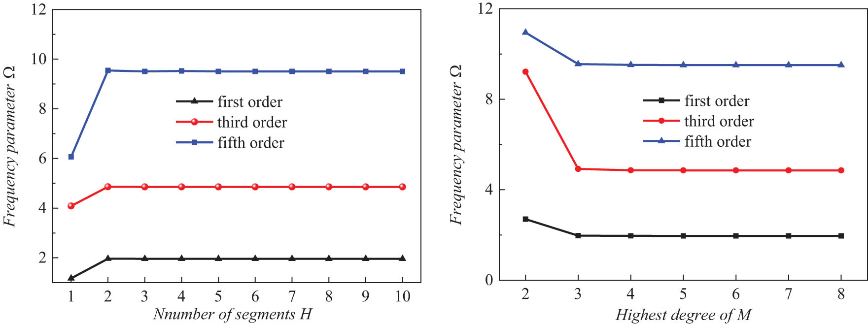
Frequency parameters Ω of rectangular plate with different convergence parameters.
As mentioned earlier, the Jacobi polynomial can be transformed into the Chebyshev polynomial or the Legendre polynomial by selecting different values of Jacobi parameters. The relative percentage errors of rectangular plates with different Jacobi parameters are shown in Figure 5, and α = β = 1 is selected as the reference value. Obviously, the maximum relative percentage error is almost negligible in the existing method regardless of the values of α and β, which means that the introduction of the Jacobi polynomial enriches the selection and diversity of displacement functions.
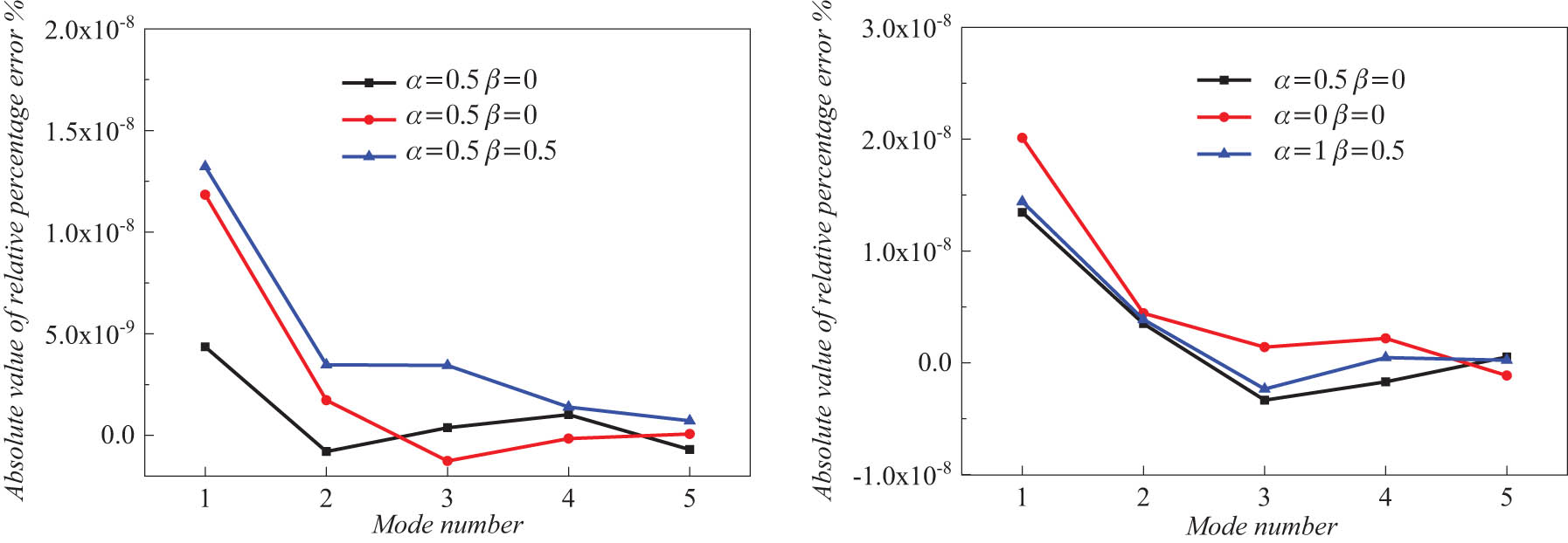
Relative percentage error of rectangular plate with different Jacobi parameters.
3.2 Free vibration characteristics of the rectangular plate
In this section, the free vibration solutions of the rectangular plate under general boundary constraints are compared with the existing literature. Table 2 shows the comparison of dimensionless frequency parameters between the proposed method and the published literature [51]. The comparison study indicates that the current method has higher accuracy for free vibration analysis of the rectangular plate. Figure 6 displays the mode shape of a rectangular plate; it is apparent that the proposed method in this paper can well display the mode shapes of the rectangular plate under general boundary conditions.
Comparison of the natural frequency of present method and published literature
| Boundary conditions | SSSS | SSSC | CSCS | ||||
|---|---|---|---|---|---|---|---|
| Mode.no | Ref. [51] | Present | Ref. [51] | Present | Ref. [51] | Present | |
| a/b = 0.4 | 1 | 7.2500 | 7.2494 | 7.4410 | 7.4447 | 7.6842 | 7.6863 |
| 2 | 10.2500 | 10.2482 | 10.8840 | 10.8832 | 11.6290 | 11.6299 | |
| 3 | 15.2500 | 15.2472 | 16.4120 | 16.4167 | 17.7090 | 17.7157 | |
| 4 | 22.2490 | 22.2462 | 23.9560 | 23.9567 | 25.8040 | 25.8022 | |
| 5 | 25.9990 | 25.9981 | 26.0930 | 26.0977 | 26.2020 | 26.2064 | |
| a/b = 0.6 | 1 | 3.7780 | 3.7775 | 4.0540 | 4.0604 | 4.4270 | 4.4310 |
| 2 | 6.7780 | 6.7772 | 7.5750 | 7.5700 | 8.5095 | 8.5052 | |
| 3 | 11.7780 | 11.7769 | 12.2540 | 12.2515 | 12.4280 | 12.4219 | |
| 4 | 12.1110 | 12.1106 | 13.1200 | 13.1131 | 14.6050 | 14.6161 | |
| 5 | 15.1110 | 15.1098 | 15.6220 | 15.6236 | 16.2170 | 16.2180 | |

The mode shape of rectangular plate.
Table 3 and Figure 7 show the dimensionless frequency parameters of a rectangular plate with different shear correction factors under general boundary restraints. It is not hard to find that the shear correction factor has little influence on the dimensionless frequency parameters. At the same time, the boundary constraint has a significant impact on the vibration characteristics of the rectangular plate, and the frequency parameter gradually increases with the enhancement of the boundary conditions, which means that the enhancement of the boundary conditions increases the overall stiffness of the structure.
Nondimensional frequency parameters of rectangular plate subject to general boundary conditions
| Mode.no | CSCS | SSSS | FSFS | ESES | CSFS | |
|---|---|---|---|---|---|---|
| κ = 3/6 | 1 | 2.8321 | 1.9450 | 0.9677 | 1.8392 | 1.2649 |
| 2 | 5.2943 | 4.7939 | 1.5970 | 3.1285 | 3.2270 | |
| 3 | 6.5499 | 4.7949 | 3.5849 | 4.6285 | 4.0913 | |
| 4 | 8.8248 | 7.4947 | 3.8355 | 5.3910 | 6.0497 | |
| 5 | 9.6420 | 9.3375 | 4.5561 | 6.3000 | 6.8901 | |
| κ = 4/6 | 1 | 2.8547 | 1.9542 | 0.9692 | 1.8753 | 1.2687 |
| 2 | 5.3465 | 4.8322 | 1.6029 | 3.2055 | 3.2498 | |
| 3 | 6.6503 | 4.8331 | 3.6058 | 4.6904 | 4.1175 | |
| 4 | 8.9775 | 7.5860 | 3.8574 | 5.4840 | 6.1128 | |
| 5 | 9.7823 | 9.4634 | 4.5889 | 6.4489 | 6.9747 | |
| κ = 5/6 | 1 | 2.8685 | 1.9601 | 0.9702 | 1.9023 | 1.2710 |
| 2 | 5.3789 | 4.8561 | 1.6067 | 3.2643 | 3.2641 | |
| 3 | 6.7130 | 4.8569 | 3.6191 | 4.7326 | 4.1336 | |
| 4 | 9.0738 | 7.6436 | 3.8708 | 5.5526 | 6.1523 | |
| 5 | 9.8699 | 9.5420 | 4.6094 | 6.5559 | 7.0275 | |
| κ = 1 | 1 | 2.8779 | 1.9642 | 0.9709 | 1.9237 | 1.2727 |
| 2 | 5.4009 | 4.8725 | 1.6093 | 3.3118 | 3.2739 | |
| 3 | 6.7558 | 4.8733 | 3.6285 | 4.7638 | 4.1446 | |
| 4 | 9.1400 | 7.6834 | 3.8799 | 5.6066 | 6.1795 | |
| 5 | 9.9298 | 9.5958 | 4.6234 | 6.6381 | 7.0636 |
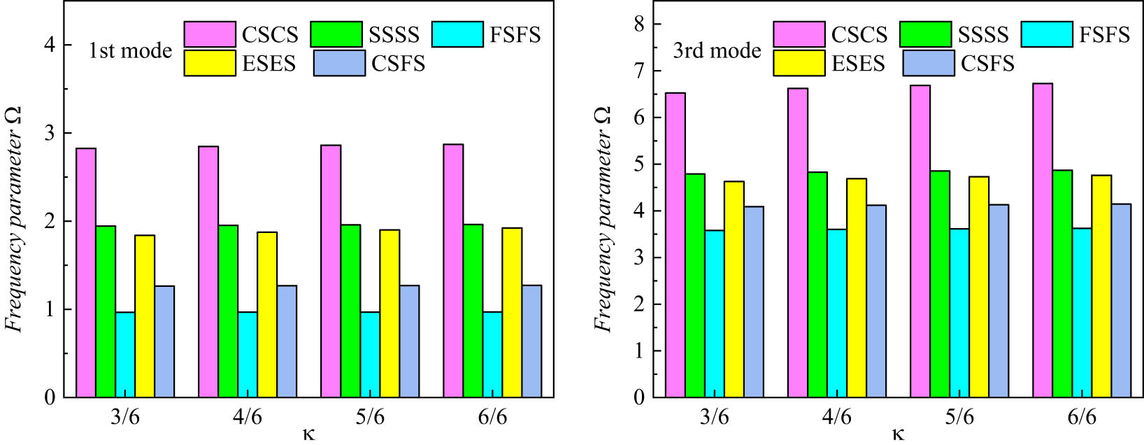
Frequency parameters Ω of rectangular plate with different shear correction factors.
Table 4 and Figure 8 display the dimensionless frequency parameters of the rectangular plate with various a/b ratios under general boundary restraints. The results indicate that the nondimensional frequency parameters gradually decrease in general with the a/b ratio increase. That is to say, when the width (b) of the rectangular plate is fixed, the overall stiffness of the structure gradually decreases as the length (a) increases.
Nondimensional frequency parameters of rectangular plate with different a/b radio
| Mode.no | CSCS | SSSS | FSFS | ESES | CSFS | |
|---|---|---|---|---|---|---|
| a/b = 0.5 | 1 | 8.9615 | 4.8231 | 0.9582 | 2.8350 | 2.2526 |
| 2 | 10.8082 | 7.5613 | 2.6810 | 5.9866 | 4.9644 | |
| 3 | 14.4478 | 12.0863 | 3.8261 | 6.0269 | 9.4592 | |
| 4 | 19.9047 | 15.7744 | 6.2370 | 10.0635 | 9.5061 | |
| 5 | 22.1490 | 18.1974 | 8.4869 | 10.7104 | 12.3241 | |
| a/b = 1 | 1 | 2.8685 | 1.9601 | 0.9702 | 1.9023 | 1.2710 |
| 2 | 5.3789 | 4.8561 | 1.6067 | 3.2643 | 3.2641 | |
| 3 | 6.7130 | 4.8569 | 3.6191 | 4.7326 | 4.1336 | |
| 4 | 9.0738 | 7.6436 | 3.8708 | 5.5526 | 6.1523 | |
| 5 | 9.8699 | 9.5420 | 4.6094 | 6.5559 | 7.0275 | |
| a/b = 2 | 1 | 1.3756 | 1.2385 | 0.9812 | 1.2771 | 1.0497 |
| 2 | 2.3614 | 1.9711 | 1.1739 | 1.9323 | 1.5786 | |
| 3 | 3.8323 | 3.1883 | 1.7673 | 2.7605 | 2.5689 | |
| 4 | 4.2299 | 4.1654 | 2.7593 | 3.8094 | 3.9586 | |
| 5 | 5.1036 | 4.8734 | 3.8973 | 4.1584 | 4.0161 |

Frequency parameters Ω of rectangular plate with different a/b ratio.
3.3 Steady vibration characteristics of the rectangular plate
In this section, the steady forced vibration analysis of the rectangular plate subjected to external excitation load is carried out. The excitation load is the unit concentrated force along the z-direction, the analysis frequency band is from 2 to 1,000 Hz, and the interval is 2 Hz.
Figure 9 displays the comparison results for the steady vibration response of the present method and FEM. Obviously, the proposed method is in good agreement with the FEM results, and the trends of the two curves are basically the same; there is only a small deviation at the single peak. In other words, the current approach can effectively analyze the steady vibration of the rectangular plate.
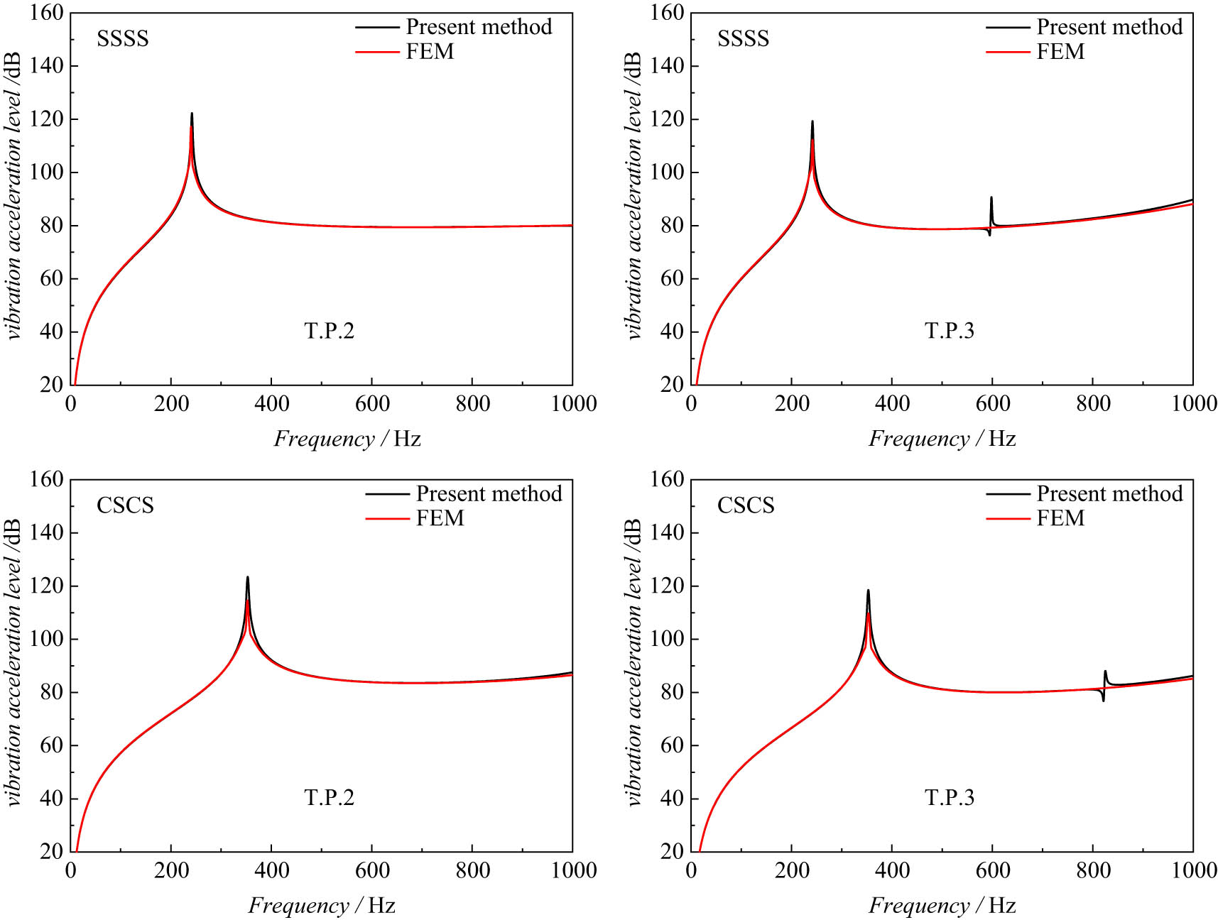
Comparison of the steady vibration response of the present method and FEM results.
After verifying the effectiveness of the proposed method for the steady forced vibration of the rectangular plate, a parametric study on the steady vibration characteristics of the rectangular plate is presented. First, Figure 10 shows the comparison results for the steady vibration response of the rectangular plate under various boundary conditions. The results indicate that the boundary conditions have a significant influence on the steady vibration response of the structure. In addition, the first peak frequency of the steady vibration gradually increases with the increase of the boundary conditions, while the number of peaks gradually decreases. At the same time, it is not difficult to find that the peak of the steady vibration appears at the natural frequency of the rectangular plate. It can be concluded that the natural frequency of the structure gradually increases with the enhancement of boundary conditions, while the number of natural frequencies of the structure within a certain frequency range decrease.
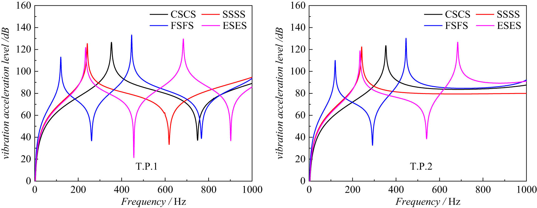
Comparison of the steady vibration of rectangular plate with different boundary conditions.
Figures 11–12 show the comparison results for the steady vibration characteristics of the rectangular plate with different h/a and a/b ratios. The results demonstrate that the first peak frequency gradually increases with increasing h/a ratio, which indicates that the increase of thickness of the rectangular plate has an obvious influence on the structural stiffness. In addition, the first peak frequency of the structure gradually decreases as the length (a) increases when the width (b) of the rectangular plate is fixed, while the number of peaks within a certain frequency range increases, which is consistent with the conclusion of free vibration.

Comparison of the steady vibration of rectangular plate with different h/a ratios.

Comparison of the steady vibration of rectangular plate with different a/b radios.
3.4 Transient vibration characteristics of rectangular plate
For transient vibration response, three different types of time-dependent loads are considered in the paper, which is shown in Figure 13.
Rectangular pulse load
(31)Sine pulse load
(32)Triangular pulse load

Sketch of applied load for rectangular plate with three different types of time-dependent loads.
First, the transient response analysis of the undamped system is carried out. Figure 14 displays comparison results for the undamped transient vibration response of present method and FEM under rectangular pulse load, in which q 0 = 1 N, t 0 = 0.005 s, τ = 0.005 s, Δt = 0.0001 s. Obviously, the proposed method is in good agreement with the FEM calculation results, and the trends of the two curves are basically the same; in other words, the present method can effectively analyze the transient vibration response for the rectangular plate.

Comparison of the undamped transient vibration response of the present method and FEM.
Figure 15 displays the comparison of the undamped transient vibration with different boundary conditions under a rectangular plate. The amplitude of the undamped vibration response increases with the weakening of boundary conditions. Undoubtedly, the weakening of boundary conditions reduces the stiffness of the structure and makes the structure more prone to vibration. Then, the comparison of the undamped transient vibration with different types of time-dependent loads under different boundary conditions is shown in Figure 16, and the vibration pickup points are chosen as point 2; the action time and amplitude of those three kinds of loads are precisely the same. The influence of the rectangular pulse load on the structure is always more significant than that of sine pulse load and triangular pulse load from the perspective of the amplitude of the displacement response at the initial moment of load application. The displacement response of the sine pulse load and the triangle pulse load is basically the same under SSSS boundary conditions, which is smaller than the displacement response caused by the rectangular pulse load with the passage of time. For CSCS boundary conditions, the response caused by the rectangular pulse load is greater than the response caused by the sine pulse load, while the response caused by the triangular pulse load is the smallest with the passage of time, owing to the amplitude of rectangular pulse load acting on the structure is larger than other loads within a certain period.
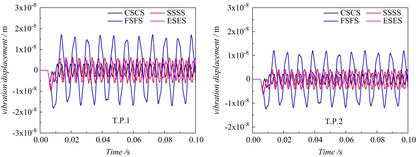
Comparison of the undamped transient vibration with different boundary conditions.

Comparison of the undamped transient vibration with different types of time-dependent loads.
For the damped transient vibration response, Figure 17 displays the comparison of the damped transient vibration with different boundary conditions under the rectangular pulse load. The amplitude of the damped vibration response increases with the weakening of the boundary condition. The comparison of the damped transient vibration with different types of time-dependent loads is shown in Figure 18. Regardless of the boundary condition, the maximum vibration displacement at the initial moment is always caused by the rectangular pulse load, followed by the sine pulse load, and the response caused by the triangle pulse load is the smallest, owing to the amplitude of the rectangular pulse load acting on the structure is larger than other loads within a certain period, which is consistent with the conclusion of the undamped vibration response.

Comparison of the damped transient vibration response with different boundary conditions.

Comparison of the damped transient vibration with different types of time-dependent loads.
4 Conclusion
In this paper, the unified Jacobi–Ritz method (JRM) is utilized to analyze the dynamic response of the rectangular plate with different boundary conditions. The rectangular plate is divided into several equal sections in the framework of the DDM, and the structural energy functional is established based on the FSDT; five groups of artificial springs are introduced to ensure the continuity of the segments and diversified boundary conditions. The unified Jacobi orthogonal polynomials are expanded to represent the displacement field of the plate in one direction, and the other direction is expressed by the trigonometric series. Polynomials such as Legendre and Chebyshev are special forms of Jacobi polynomial; in other words, the introduction of Jacobi polynomials enriches the selection and diversity of displacement functions.
The free, steady, and transient vibration characteristics of the rectangular plate have been well analyzed by utilizing the Rayleigh–Ritz method, in which the Newmark-β integration method is adopted to realize the time-domain solutions for transient vibration response, especially for the damped transient vibration response, as well as the good convergence and feasibility of the present method have been proved. The effectiveness of the proposed method is verified by comparing it with the existing literature and FEM results.
The calculation results of the vibration characteristics for the rectangular plate under different boundary conditions, structural scale parameters, and load types are given, indicating that the constraint conditions and geometric dimensions have a significant impact on the dynamic response of the rectangular plate. The results of the study can support the vibration control of the plate structure and further enrich the research data of the JRM.
Acknowledgments
This research was supported by Harbin Engineering University and Naval Research Institute.
-
Funding information: This study was funded by the National Natural Science Foundation of China (U2006229, 52101351), Ph.D. Student Research and Innovation Fund of the Fundamental Research Funds for the Central Universities (3072020GIP0102), and “Quick Response” Special Project of Harbin Engineering University (3072020CFT0111).
-
Author Contributions: Di Jia: Writing and Editing. Cong Gao: Methodology and investigation. Yuliang Yang: Editing and Revision. Fuzhen Pang: Conceptualization and Methodology. Haichao Li: Revision. Yuan Du: Validation.
-
Conflict of interest: The authors declare that there is no conflict of interest regarding the publication of this paper.
-
Data availability statement: The data used to support the findings of this study are included within the article.
References
[1] Kolarevic, N., M. Nefovska-Danilovic, and M. Petronijevic. Dynamic stiffness elements for free vibration analysis of rectangular Mindlin plate assemblies. Journal of Sound & Vibration, Vol. 359, 2015, pp. 84–106.10.1016/j.jsv.2015.06.031Search in Google Scholar
[2] Kirisik, R. and S. Yueksel. Free vibration analysis of a rectangular plate with Kelvin type boundary conditions. Shock & Vibration, Vol. 14, No. 6, 2013, pp. 447–457.10.1155/2007/307575Search in Google Scholar
[3] Gupta, A. K. and P. Singhal. Thermal effect on free vibration of non-homogeneous orthotropic visco-elastic rectangular plate of parabolically varying thickness. Applied Mathematics, Vol. 1, No. 6, 2010, pp. 456–463.10.4236/am.2010.16060Search in Google Scholar
[4] Su, X., E. Bai, and A. Chen. Symplectic superposition solution of free vibration of fully clamped orthotropic rectangular thin plate on two-parameter elastic foundation. International Journal of Structural Stability and Dynamics, Vol. 21, No. 9, 2021, id. 2150122.10.1142/S0219455421501224Search in Google Scholar
[5] Li, H., F. Pang, H. Chen, and Y. Du. Vibration analysis of functionally graded porous cylindrical shell with arbitrary boundary restraints by using a semi analytical method. Composites Part B: Engineering, Vol. 164, 2019, pp. 249–264.10.1016/j.compositesb.2018.11.046Search in Google Scholar
[6] Du, Y., D. Jia, H. Li, C. Gao, and H. Wang. A unified method to analyze free and forced vibration of stiffened plates under various edge conditions. European Journal of Mechanics a-Solids, Vol. 94, 2022, id. 104573.10.1016/j.euromechsol.2022.104573Search in Google Scholar
[7] Qin, Z., F. Chu, and J. Zu. Free vibrations of cylindrical shells with arbitrary boundary conditions: a comparison study. International Journal of Mechanical Sciences, Vol. 133, 2017, pp. 91–99.10.1016/j.ijmecsci.2017.08.012Search in Google Scholar
[8] Liu, Y., Z. Qin, and F. Chu. Nonlinear forced vibrations of FGM sandwich cylindrical shells with porosities on an elastic substrate. Nonlinear Dynamics, Vol. 104, No. 2, 2021, pp. 1007–1021.10.1007/s11071-021-06358-7Search in Google Scholar
[9] Shi, D., H. Zhang, Q. Wang, and S. Zha. Free and forced vibration of the moderately thick laminated composite rectangular plate on various elastic winkler and pasternak foundations. Shock and Vibration, Vol. 2017, No. PT.4, 2017, pp. 1–23.10.1155/2017/7820130Search in Google Scholar
[10] Javani M., Y. Kiani, and M.R. Eslami. Application of generalized differential quadrature element method to free vibration of FG-GPLRC T-shaped plates. Engineering Structures, Vol. 242, 2021, id. 112510.10.1016/j.engstruct.2021.112510Search in Google Scholar
[11] Huang, J., Y. Tang, H. Li, F. Pang, and Y. Qin. Vibration characteristics analysis of composite floating rafts for marine structure based on modal superposition theory. Reviews on Advanced Materials Science, Vol. 60, No. 1, 2021, pp. 719–730.10.1515/rams-2021-0043Search in Google Scholar
[12] Gao, C., H. Zhang, H. Li, F. Pang, and H. Wang. Numerical and experimental investigation of vibro-acoustic characteristics of a submerged stiffened cylindrical shell excited by a mechanical force. Ocean Engineering, Vol. 249, 2022, id. 110913.10.1016/j.oceaneng.2022.110913Search in Google Scholar
[13] Yang, J., J. Liu, and J. Li. Analysis of a rectangular ceramic plate in electrically forced thickness-twist vibration as a piezoelectric transformer. IEEE Transactions on Ultrasonics, Ferroelectrics and Frequency Control, Vol. 54, No. 4, 2007, pp. 830–835.10.1109/TUFFC.2007.316Search in Google Scholar PubMed
[14] Akbarov, S. D., N. Yahnioglu, and U. B. Yesil. 3D analysis of the forced vibration of a prestressed rectangular composite platewith two neighboring cylindrical cavities. Computers Materials & Continua, Vol. 28, No. 2, 2012, pp. 147–164.Search in Google Scholar
[15] Wu, C. F., S. H. Liu, and Y. J. Chen. Applying the principle of mixed variables solve the problems of forced vibration of the calculating rectangular plate by uniform load. Applied Mechanics & Materials, Vol. 71–78, 2011, pp. 1715–1719.10.4028/www.scientific.net/AMM.71-78.1715Search in Google Scholar
[16] Fan, Z. The effects of viscoelastic boundary supports on the forced vibration of a rectangular plate. Journal of Vibration Engineering, Vol. 14, 2001, pp. 183–186.Search in Google Scholar
[17] Xiao, Y. G. and C. P. Yang. Free vibration analysis for disconnected thin rectangular plate with four free edges on nonlinear elastic foundation. Applied Mechanics & Materials, Vol. 52–54, 2011, pp. 1309–1314.10.4028/www.scientific.net/AMM.52-54.1309Search in Google Scholar
[18] Xiao, Y. G., C. P. Yang, and H. Hu. Nonlinear forced vibration analysis for thin rectangular plate on nonlinear elastic foundation. Applied Mechanics & Materials, Vol. 204–208, 2013, pp. 4716–4721.10.4028/www.scientific.net/AMM.204-208.4716Search in Google Scholar
[19] Zhong, Z., Y. Xiao, and C. Yang. Nonlinear forced vibration analysis for thin rectangular plate on nonlinear elastic foundation. Research Journal of Applied Sciences, Engineering and Technology, Vol. 5, No. 9, 2013, pp. 2163–2167.10.19026/rjaset.5.4767Search in Google Scholar
[20] Zhang, C. L., W. Q. Chen, and J. S. Yang. Electrically forced vibration of a rectangular piezoelectric plate of monoclinic crystals. International Journal of Applied Electromagnetics & Mechanics, Vol. 31, No. 4, 2009, pp. 207–218.10.3233/JAE-2009-1058Search in Google Scholar
[21] Nasirshoaibi, M. and N. Mohammadi. Forced transverse vibration analysis of an elastically connected rectangular double-plate system with a Pasternak middle layer. ARPN Journal of Engineering and Applied Sciences, Vol. 10, No. 14, 2015, pp. 6004–6013.Search in Google Scholar
[22] Wang, Q., D. Shi, Q. Liang, and F. Pang. Free vibration of four-parameter functionally graded moderately thick doubly-curved panels and shells of revolution with general boundary conditions. Applied Mathematical Modelling, Vol. 42, 2017, pp. 705–734.10.1016/j.apm.2016.10.047Search in Google Scholar
[23] Wang, Q., X. Cui, B. Qin, Q. Liang, and J. Tang. A semi-analytical method for vibration analysis of functionally graded (FG) sandwich doubly-curved panels and shells of revolution. International Journal of Mechanical Sciences, Vol. 134, 2017, pp. 479–499.10.1016/j.ijmecsci.2017.10.036Search in Google Scholar
[24] Agarana, M. C. and A. I. Ehigbochie. Forced vibration numerical analysis of rectangular elastic orthotropic damped inclined mindlin plate using finite difference algorithm. Applied Mathematics, Vol. 9, No. 6, 2018, pp. 618–632.10.4236/am.2018.96043Search in Google Scholar
[25] Yahnioglu, N. and U. B. Yesil. Forced vibration of an initial stressed rectangular composite thick plate with a cylindrical hole. ASME International Mechanical Engineering Congress & Exposition, Vol. 15, 2009, pp. 337–343.10.1115/IMECE2009-10475Search in Google Scholar
[26] Ju-Hai, M. A. The method of mixed variables for solving the problems of forced vibration of the rectangular plate under uniform load. World Earthquake Engineering, Vol. 23, No. 3, 2007, pp. 158–162.Search in Google Scholar
[27] Chen, X., L. Chen, S. Huang, M. Li, and X. Li. Nonlinear forced vibration of in-plane bi-directional functionally graded materials rectangular plate with global and localized geometrical imperfections – ScienceDirect. Applied Mathematical Modelling, Vol. 93, 2021, pp. 443–466.10.1016/j.apm.2020.12.033Search in Google Scholar
[28] Kim, S. M. Influence of horizontal resistance at plate bottom on vibration of plates on elastic foundation under moving loads. Engineering Structures, Vol. 26, No. 4, 2004, pp. 519–529.10.1016/j.engstruct.2003.12.002Search in Google Scholar
[29] Niu Y, and M. Yao. Linear and nonlinear vibrations of graphene platelet reinforced composite tapered plates and cylindrical panels. Aerospace Science and Technology, Vol. 115, 2021, id. 106798.10.1016/j.ast.2021.106798Search in Google Scholar
[30] Yang, Y., B. Chen, W. Lin, Y. Li, and Y. Dong. Vibration and symmetric thermal buckling of asymmetric annular sandwich plates with piezoelectric/GPLRC layers rested on foundation. Aerospace Science and Technology, Vol. 110, 2021, id. 106495.10.1016/j.ast.2021.106495Search in Google Scholar
[31] Gunasekaran, V., J. Pitchaimani, and L. Chinnapandi. Vibro-acoustics response of an isotropic plate under non-uniform edge loading: An analytical investigation. Aerospace Science and Technology, Vol. 105, 2020, id. 106052.10.1016/j.ast.2020.106052Search in Google Scholar
[32] Ou, D. and C. M. Mak. Transient vibration and sound radiation of a stiffened plate. Journal of Vibration and Control, Vol. 19, No. 9, 2013, pp. 1378–1385.10.1177/1077546312450731Search in Google Scholar
[33] Fan, Z. Transient vibration and sound radiation of a rectangular plate with viscoelastic boundary supports. International Journal for Numerical Methods in Engineering, Vol. 51, No. 5, 2001, pp. 619–630.10.1002/nme.197.absSearch in Google Scholar
[34] Geng, L., X. Zhang, Y. Zhang, and L. Xu. Reconstruction of transient vibration and sound radiation of an impacted plate[C]//INTER-NOISE and NOISE-CON Congress and Conference Proceedings. Institute of Noise Control Engineering, Vol. 253, No. 6, 2016, pp. 2288–2295.Search in Google Scholar
[35] Geng, L., X. Z. Zhang, and C. X. Bi. Reconstruction of transient vibration and sound radiation of an impacted plate using time domain plane wave superposition method. Journal of Sound & Vibration, Vol. 344, 2015, pp. 114–125.10.1016/j.jsv.2015.01.046Search in Google Scholar
[36] He, G. and M. Kashiwagi. Nonlinear solution for vibration of vertical plate and transient waves generated by wave impact. International Journal of Offshore & Polar Engineering, Vol. 19, No. 19, 2009, pp. 189–197.Search in Google Scholar
[37] Sheikh, A. H. and M. Mukhopadhyay. Linear and nonlinear transient vibration analysis of stiffened plate structures. Finite Elements in Analysis and Design, Vol. 38, No. 6, 2002, pp. 477–502.10.1016/S0168-874X(01)00081-6Search in Google Scholar
[38] Hajheidari, H. and H. R. Mirdamadi. Free and transient vibration analysis of an un-symmetric cross-ply laminated plate by spectral finite elements. Acta Mechanica, Vol. 223, No. 11, 2012, pp. 2477–2492.10.1007/s00707-012-0719-8Search in Google Scholar
[39] Skočilas, J., B. Skočilasová, and J. Soukup. Determination of the rheological properties of thin plate under transient vibration. Latin American Journal of Solids & Structures, Vol. 10, No. 1, 2013, pp. 189–195.10.1590/S1679-78252013000100018Search in Google Scholar
[40] Pang, F., Y. Qin, H. Li, Y. Teng, Q. Gong, and S. Wang. Study on impact resistance of composite rocket launcher. Reviews on Advanced Materials Science, Vol. 60, No. 1, 2021, pp. 615–630.10.1515/rams-2021-0045Search in Google Scholar
[41] Pang, F., H. Li, H. Chen, and Y. Shan. Free vibration analysis of combined composite laminated cylindrical and spherical shells with arbitrary boundary conditions. Mechanics of Advanced Materials and Structures, Vol. 28, No. 2, 2021, pp. 182–199.10.1080/15376494.2018.1553258Search in Google Scholar
[42] Gao, C., F. Pang, H. Li, and L. Li. An approximate solution for vibrations of uniform and stepped functionally graded spherical cap based on Ritz method. Composite Structures, Vol. 233, 2020, id. 111640.10.1016/j.compstruct.2019.111640Search in Google Scholar
[43] Li, H., F. Pang, X. Miao, and Y. Li. Jacobi–Ritz method for free vibration analysis of uniform and stepped circular cylindrical shells with arbitrary boundary conditions: A unified formulation. Computers & Mathematics with Applications, Vol. 77, No. 7, 2019, pp. 427–440.10.1016/j.camwa.2018.09.046Search in Google Scholar
[44] Gao, C., F. Pang, H. Li, H. Wang, J. Cui, and J. Huang. Free and forced vibration characteristics analysis of a multispan timoshenko beam based on the Ritz method. Shock and Vibration, Vol. 2021, 2021, id. 4440250. (WOS: 000683141400004).10.1155/2021/4440250Search in Google Scholar
[45] Du, Y., F. Pang, L. Sun, and H. Li. A unified formulation for dynamic behavior analysis of spherical cap with uniform and stepped thickness distribution under different edge constraints. Thin-Walled Structures, Vol. 146, 2020, id. 106445.10.1016/j.tws.2019.106445Search in Google Scholar
[46] Gao, C., F. Pang, H. Li, D. Jia, and Y. Tang. Steady and transient vibration analysis of uniform and stepped annular/circular plates based on FSDT. Acta Mechanica, Vol. 233, No. 3, 2022, pp. 1061–1082.10.1007/s00707-022-03157-ySearch in Google Scholar
[47] Su, Z., G. Jin, and T. Ye. Free vibration analysis of moderately thick functionally graded open shells with general boundary conditions. Composite Structures, Vol. 117, 2014, pp. 169–186.10.1016/j.compstruct.2014.06.026Search in Google Scholar
[48] Shi, Z., X. Yao, F. Pang, and Q. Wang. An exact solution for the free-vibration analysis of functionally graded carbon-nanotube-reinforced composite beams with arbitrary boundary conditions. Scientific reports, Vol. 7, No. 1, 2017, id. 12909.10.1038/s41598-017-12596-wSearch in Google Scholar PubMed PubMed Central
[49] Qin, Z., Z. Yang, J. Zu, and F. Chu. Free vibration analysis of rotating cylindrical shells coupled with moderately thick annular plates. International Journal of Mechanical Sciences, Vol. 142, 2018, pp. 127–139.10.1016/j.ijmecsci.2018.04.044Search in Google Scholar
[50] Ilanko, S., L. Monterrubio, and Y. Mochida. The Rayleigh–Ritz method for structural analysis. John Wiley & Sons, 2014.10.1002/9781118984444Search in Google Scholar
[51] Xing Y, and B. Liu. Closed form solutions for free vibrations of rectangular Mindlin plates[J]. Acta Mechanica Sinica, Vol. 25, No. 5, 2009, pp. 689–698.10.1007/s10409-009-0253-7Search in Google Scholar
© 2022 Di Jia et al., published by De Gruyter
This work is licensed under the Creative Commons Attribution 4.0 International License.
Articles in the same Issue
- Review Articles
- State of the art, challenges, and emerging trends: Geopolymer composite reinforced by dispersed steel fibers
- A review on the properties of concrete reinforced with recycled steel fiber from waste tires
- Copper ternary oxides as photocathodes for solar-driven CO2 reduction
- Properties of fresh and hardened self-compacting concrete incorporating rice husk ash: A review
- Basic mechanical and fatigue properties of rubber materials and components for railway vehicles: A literature survey
- Research progress on durability of marine concrete under the combined action of Cl− erosion, carbonation, and dry–wet cycles
- Delivery systems in nanocosmeceuticals
- Study on the preparation process and sintering performance of doped nano-silver paste
- Analysis of the interactions between nonoxide reinforcements and Al–Si–Cu–Mg matrices
- Research Articles
- Study on the influence of structural form and parameters on vibration characteristics of typical ship structures
- Deterioration characteristics of recycled aggregate concrete subjected to coupling effect with salt and frost
- Novel approach to improve shale stability using super-amphiphobic nanoscale materials in water-based drilling fluids and its field application
- Research on the low-frequency multiline spectrum vibration control of offshore platforms
- Multiple wide band gaps in a convex-like holey phononic crystal strip
- Response analysis and optimization of the air spring with epistemic uncertainties
- Molecular dynamics of C–S–H production in graphene oxide environment
- Residual stress relief mechanisms of 2219 Al–Cu alloy by thermal stress relief method
- Characteristics and microstructures of the GFRP waste powder/GGBS-based geopolymer paste and concrete
- Development and performance evaluation of a novel environmentally friendly adsorbent for waste water-based drilling fluids
- Determination of shear stresses in the measurement area of a modified wood sample
- Influence of ettringite on the crack self-repairing of cement-based materials in a hydraulic environment
- Multiple load recognition and fatigue assessment on longitudinal stop of railway freight car
- Synthesis and characterization of nano-SiO2@octadecylbisimidazoline quaternary ammonium salt used as acidizing corrosion inhibitor
- Perforated steel for realizing extraordinary ductility under compression: Testing and finite element modeling
- The influence of oiled fiber, freeze-thawing cycle, and sulfate attack on strain hardening cement-based composites
- Perforated steel block of realizing large ductility under compression: Parametric study and stress–strain modeling
- Study on dynamic viscoelastic constitutive model of nonwater reacted polyurethane grouting materials based on DMA
- Mechanical behavior and mechanism investigation on the optimized and novel bio-inspired nonpneumatic composite tires
- Effect of cooling rate on the microstructure and thermal expansion properties of Al–Mn–Fe alloy
- Research on process optimization and rapid prediction method of thermal vibration stress relief for 2219 aluminum alloy rings
- Failure prevention of seafloor composite pipelines using enhanced strain-based design
- Deterioration of concrete under the coupling action of freeze–thaw cycles and salt solution erosion
- Creep rupture behavior of 2.25Cr1Mo0.25V steel and weld for hydrogenation reactors under different stress levels
- Statistical damage constitutive model for the two-component foaming polymer grouting material
- Nano-structural and nano-constraint behavior of mortar containing silica aggregates
- Influence of recycled clay brick aggregate on the mechanical properties of concrete
- Effect of LDH on the dissolution and adsorption behaviors of sulfate in Portland cement early hydration process
- Comparison of properties of colorless and transparent polyimide films using various diamine monomers
- Study in the parameter influence on underwater acoustic radiation characteristics of cylindrical shells
- Experimental study on basic mechanical properties of recycled steel fiber reinforced concrete
- Dynamic characteristic analysis of acoustic black hole in typical raft structure
- A semi-analytical method for dynamic analysis of a rectangular plate with general boundary conditions based on FSDT
- Research on modification of mechanical properties of recycled aggregate concrete by replacing sand with graphite tailings
- Dynamic response of Voronoi structures with gradient perpendicular to the impact direction
- Deposition mechanisms and characteristics of nano-modified multimodal Cr3C2–NiCr coatings sprayed by HVOF
- Effect of excitation type on vibration characteristics of typical ship grillage structure
- Study on the nanoscale mechanical properties of graphene oxide–enhanced shear resisting cement
- Experimental investigation on static compressive toughness of steel fiber rubber concrete
- Study on the stress field concentration at the tip of elliptical cracks
- Corrosion resistance of 6061-T6 aluminium alloy and its feasibility of near-surface reinforcements in concrete structure
- Effect of the synthesis method on the MnCo2O4 towards the photocatalytic production of H2
- Experimental study of the shear strength criterion of rock structural plane based on three-dimensional surface description
- Evaluation of wear and corrosion properties of FSWed aluminum alloy plates of AA2020-T4 with heat treatment under different aging periods
- Thermal–mechanical coupling deformation difference analysis for the flexspline of a harmonic drive
- Frost resistance of fiber-reinforced self-compacting recycled concrete
- High-temperature treated TiO2 modified with 3-aminopropyltriethoxysilane as photoactive nanomaterials
- Effect of nano Al2O3 particles on the mechanical and wear properties of Al/Al2O3 composites manufactured via ARB
- Co3O4 nanoparticles embedded in electrospun carbon nanofibers as free-standing nanocomposite electrodes as highly sensitive enzyme-free glucose biosensors
- Effect of freeze–thaw cycles on deformation properties of deep foundation pit supported by pile-anchor in Harbin
- Temperature-porosity-dependent elastic modulus model for metallic materials
- Effect of diffusion on interfacial properties of polyurethane-modified asphalt–aggregate using molecular dynamic simulation
- Experimental study on comprehensive improvement of shear strength and erosion resistance of yellow mud in Qiang Village
- A novel method for low-cost and rapid preparation of nanoporous phenolic aerogels and its performance regulation mechanism
- In situ bow reduction during sublimation growth of cubic silicon carbide
- Adhesion behaviour of 3D printed polyamide–carbon fibre composite filament
- An experimental investigation and machine learning-based prediction for seismic performance of steel tubular column filled with recycled aggregate concrete
- Effects of rare earth metals on microstructure, mechanical properties, and pitting corrosion of 27% Cr hyper duplex stainless steel
- Application research of acoustic black hole in floating raft vibration isolation system
- Multi-objective parametric optimization on the EDM machining of hybrid SiCp/Grp/aluminum nanocomposites using Non-dominating Sorting Genetic Algorithm (NSGA-II): Fabrication and microstructural characterizations
- Estimating of cutting force and surface roughness in turning of GFRP composites with different orientation angles using artificial neural network
- Displacement recovery and energy dissipation of crimped NiTi SMA fibers during cyclic pullout tests