Deterioration of concrete under the coupling action of freeze–thaw cycles and salt solution erosion
-
Hao Li
 and
Yuan Zhang
and
Yuan Zhang

Abstract
In this article, the deterioration law of concrete under the coupling action of freeze–thaw cycles and salt solution erosion is studied through the comprehensive thermal analysis, the field emission electron microscope, and the nuclear magnetic resonance, and the influence of salt solution type and salt solution concentration is considered. The results show that the freeze–thaw damage of concrete in the salt solution is the combined effect of the expansion pressure of the freeze–thaw erosion product, the crystallization pressure of the salt solution, and the frost heave pressure of the fresh water; the damage degree increases with the increase of freezing and thawing cycles; the damage degree of concrete in the chloride solution is greater than that in the sulfate solution and fresh water before 150 freezing and thawing cycles; the damage degree of concrete in the sulfate solution is greater than that in the chloride solution after 150 freezing and thawing cycles; the pores size of concrete in the salt solution is larger than that in fresh water, the main peak of the difference of pore size proportion shifts to the harmful pore area, and the secondary peak and third peak appear in the seriously harmful pore area; the pore diameters of the main peak, the secondary peak and the third peak of concrete in different salt solution, and the limiting pore diameters are 0.0662, 1.145, and 10.116 μm, respectively; the safe service life of concrete in salt solution environment after freezing and thawing cycles is predicted by the Weibull distributed life evaluation model. The maximum life after the freeze–thaw cycle is 33 years, which is at least 42% lower than that in the fresh water environment after freezing and thawing cycles.
1 Introduction
The Eurasian continent, North America continent, and southeastern South America at 40–60° north-south latitude belong to the typical temperate continental climate. Due to the long distance from the ocean or the obstruction of topographical features, it is difficult for the humid ocean airflow to reach the area, so the climate is dry and the rainfall is low, which leads to the extremely high salt content in rocks, lakes, and groundwater, most of which are salt solutions composed of corrosive ions such as chloride ions, sulfate ions, sodium ions, and magnesium ions [1,2,3,4]. The erosion of sulfate ions and chloride ions is one of the main reasons that cause concrete damage [5]. Sulfate ions and chloride ions chemically reacted with the internal ions of the concrete to generate expansive and extensible reaction products, which cause the internal microstructure of the concrete to expand, deteriorate, and collapse, and ultimately lead to the destruction of the concrete. In addition, the mid-to-high latitudes above 40° north-south latitudes lasted for a long time in winter, with extremely low temperatures, large temperature differences between day and night, and the concrete structure often suffered from the freeze–thaw damage [6], and hence, concrete structures in mid-to-high latitudes were damaged by the coupling of salt solution erosion and freezing and thawing cycles.
Currently, some scholars have carried out some research on the durability of concrete under the condition of salt solution. An et al. [7] investigated the freeze–thaw damage of concrete in 5% NaCl solution and found that internal damage of concrete could be repaired by filling pores less than 100 nm with reaction products. Yan et al. [8] found that the water absorption and porosity of high-strength concrete gradually increased with the increase of the number of freeze–thaw cycles. Yuan et al. [9] reported that the sulfate solution had both inhibitory and promoting effects on the freeze–thaw damage of concrete, and the promoting effect increased with the increase of sulfate concentration. Liu et al. [10] investigated the sodium sulfate salt crystallization distress on carbonized concrete and found that the sodium sulfate crystallization was the main cause of concrete damage. Tan et al. [11] found that the magnesium sulfate and the elastic load had a significant impact on the mechanical properties of concrete. Alnahhal et al. [12] studied the crack evolution and performance degradation of concrete under the magnesium sulfate environment. Zhou et al. [13] and Wang et al. [14] investigated the performance evolution and mechanism of asphalt under the action of chloride salt erosion. Tian et al. [15,16] investigated the bond strength between rebar and recycled coarse aggregate concrete and found that the bond strength decreased with the increase of salt-frost cycles. However, the influence of sulfate on the frost resistance of concrete was not considered in these studies. Wen [17], Hu and Wu [18], and Tian et al. [19,20] conducted research on the salt frost resistance of concrete and found that the concrete damage in the salt solution was greater than that in fresh water under the same freeze–thaw cycles. However, they did not consider the effect of different salt solutions on concrete performance.
In summary, the current research is limited to a single concentration and single type of salt solution, and there are few studies on the freeze–thaw damage and degradation laws of concrete in different concentrations and different types of salt solutions. The objective of this article is to investigate the deterioration law of concrete under the coupling action of freeze–thaw cycle and salt solution erosion by considering different types of salt solutions and different salt solution concentrations, and to evaluate the freeze–thaw durability life of concrete based on the freeze–thaw damage theory.
2 Experimental program
2.1 Materials
In this article, the coarse aggregate (CA) was gravel with a particle size of 4.75–31.5 mm, and fine aggregate (FA) was natural river sand. The typical physical characteristics of CA and FA are listed in Tables 1 and 2, respectively. The sieving results of CA and FA are shown in Figures 1 and 2, respectively. The cement was P. O. 42.5 ordinary Portland cement produced by Hohhot Jidong Cement Co., Ltd., and the cement properties are listed in Table 3. The fly ash obtained was Grade II fly ash produced by Hohhot Jinqiao Thermal Power Co., Ltd, and the fly ash properties are listed in Table 4. The water-reducing agent adopts naphthalene-based powder water-reducing agent, and the water-reducing efficiency was 16% (Table 5).
Properties of CA
| Volume density (kg·m−3) | Apparent density (kg·m−3) | Soil content (%) | Crush index (%) |
|---|---|---|---|
| 1,570 | 2,695 | 0.6 | 3.80 |
Properties of FA
| Volume density (kg·m−3) | Apparent density (kg·m−3) | Soil content (%) | Water absorption (%) | Fineness module |
|---|---|---|---|---|
| 1,639 | 2,631 | 0.5 | 1.32 | 3.0 |
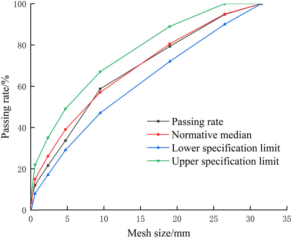
Grading curve of CA.
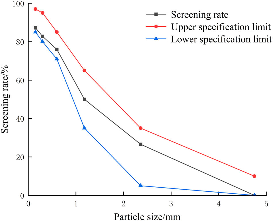
Grading curve of FA.
Properties of cement
| Specific surface area (m2/kg) | Initial setting times (min) | Final setting times (min) | Contents of SO2 (%) | Ignition loss (%) |
|---|---|---|---|---|
| 376 | 160 | 325 | 2.30 | 2.54 |
Properties of fly ash
| Specific surface area (m2/kg) | Fineness (%) | Ignition loss (%) | Contents of SO2 (%) |
|---|---|---|---|
| 496 | 8.40 | 2.90 | 0.80 |
2.2 Mixture proportions and cubic compressive strength
Table 5 shows the mixture proportions of concrete. The specimens were cured for 36 h after being fabricated, then demolded and cured for 28 days. During the curing process, the concrete cubic compressive strength of different ages was tested, and the test results are shown in Table 6.
Mixture proportions of concrete
| Water (kg·m−3) | Cement (kg·m−3) | CA (kg·m−3) | FA (kg·m−3) | Fly ash (kg·m−3) | Water-reducing agent (kg·m−3) |
|---|---|---|---|---|---|
| 160 | 298 | 1,214 | 654 | 74 | 1.12 |
Cubic compressive strength of different ages
| Age of concrete (days) | Cubic compressive strength (MPa) |
|---|---|
| 7 | 31.78 |
| 14 | 32.70 |
| 21 | 34.81 |
| 28 | 36.10 |
2.3 Specimens
The working condition design of concrete specimens is presented in Table 7.
Working conditions of concrete specimens
| Solution type | Chloride concentration (g·L−1) | Sulfate concentration (g·L−1) |
|---|---|---|
| QS* | — | — |
| C-1 | 1.3 | 0.53 |
| C-2 | 39.0 | 15.9 |
| C-3 | 51.5 | 26.5 |
| S-1 | — | 0.53 |
| S-2 | — | 15.9 |
| S-3 | — | 26.5 |
*QS is fresh water.
2.4 Test method
The concrete specimens cured for 24 days were put into the solution under different working conditions for 4 days to make the specimens saturated with water. Then, the rapid freeze–thaw test was carried out according to the Standard for Test Methods of Long-term Performance and Durability of Ordinary Concrete (GBT50082-2009) [21].
Sigma 500/VP field emission scanning electron microscope (SEM) and TG/DTA7300-integrated thermal analyzer were used to observe the internal microstructure of concrete in different salt solution types and analyze the mineral composition and element content of the erosion products.
Before the nuclear magnetic resonance test, the concrete was cut into the concrete specimen of Φ = 50 mm, and the specimens absorbed water for 24 h in a vacuum environment of −0.1 MPa to reach the saturated water absorption state, and then, specimens are placed into the low magnetic field of nuclear magnetic resonance testing machine for testing. The T2 spectrum can be obtained after inversion of the measured spectrum signal, and the pore characteristic quantity of concrete can be measured at the same time [22].
3 Results and analysis
3.1 Microstructure analysis
The microscopic morphology of concrete after freeze–thaw cycles is shown in Figure 3. Figure 3(a) and (b) show that the interior of the concrete was relatively dense before the freeze–thaw cycle, but there was still incompletely hydrated gel material inside, which was mainly concentrated in the interface transition zone at the small-sized aggregate, which was similar to that reported by Elsharief et al. [23]. At the same time, the layered Ca(OH)2 and the clustered C–S–H gel were formed inside. Due to the large amount of Ca(OH)2, it formed needle-shaped ettringite crystals (AFt) in some small cavities with water and sulfate ions, which compacted the internal pores of the concrete. Yuebo et al. [24] found that the hydration products of concrete in the chloride environment would combine with Cl– to generate a large amount of Friedel salt, and OH– would be released during the reaction, which would combine with Ca ions to form Ca(OH)2. Although there were no large-scale developed cracks in the concrete after freezing and thawing cycles, a large amount of hexagonal plate-shaped Friedel salt appeared in the ettringite crystal (AFt) cluster in the transition zone between the cement paste and the aggregate interface. At the same time, the amount of Ca(OH)2 increased. The production of Friedel salt and Ca(OH)2 reduced the interfacial cohesive force, leading to the freeze–thaw damage of concrete, which was similar to that reported by Zongxi et al. [25].
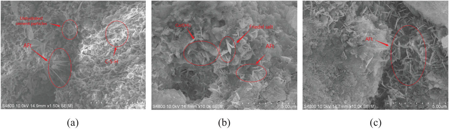
Microscopic morphology of concrete after freeze–thaw cycles: (a) 0 freeze–thaw cycles, (b) 200 freeze–thaw cycles in the chlorine solution, and (c) 200 freeze–thaw cycles in the sulfate solution.
Figure 3(c) shows that after freeze–thaw cycles in the sulfate solution, the amount of Ca(OH)2 and cluster-like C–S–H gel decreased, gradually separated and decomposed, and obvious developmental cracks appeared in the concrete internal structure, and a lot of AFt growing in all directions were generated in the gaps and a large number of AFt also caused the cracks to develop rapidly, eventually leading to the expansion failure of concrete.
The comprehensive thermal analysis diagram of concrete is shown in Figure 4. It can be seen that the hydration products in concrete gradually decreased as the number of freeze–thaw cycles increased, while the types and content of erosion products gradually increased. By comparing with the literature [25,26,27], it can be seen that the endothermic peak at 70°C was the evaporation of nonchemically bound water; the endothermic peak at 80–140°C was the primary dehydration of monosulfide hydrated calcium sulfoaluminate (AFm) and C–S–H; the endothermic peak at 260–280°C was the secondary dehydration of AFm and C–S–H; the endothermic peak at 420°C was caused by the decomposition of Ca(OH)2, and the endothermic peak at 670°C was caused by the thermal decomposition of calcite in the aggregate. As shown in Figure 4(b), the endothermic peak at 80–140°C and 420°C of the concrete in the salt solution after freezing and thawing cycles was significantly reduced compared with that without freezing and thawing cycles, indicating that C–S–H and Ca(OH)2 were consumed in the erosion process and converted into other substances. Yuebo et al. [24] and Ying [29] had confirmed that the conversion products were Friedel salt and Ettringite. The endothermic peak of concrete in the salt solution after freezing and thawing cycles increased at 80–140°C, 150–200°C, and 850–900°C, which is due to the increase of ettringite and mirabilite content in the erosion products. At 150–200°C, the corrosion product mirabilite was dehydrated into sodium sulfate, and gypsum was dehydrated into hemihydrate gypsum. At 850°C, the sodium sulfate melted by absorbing heat. The concrete in the chlorine solution after freezing and thawing cycles had an obvious endothermic peak at 360°C, which is due to the increase in the content of Friedel salt as the number of freezing and thawing cycles increases.
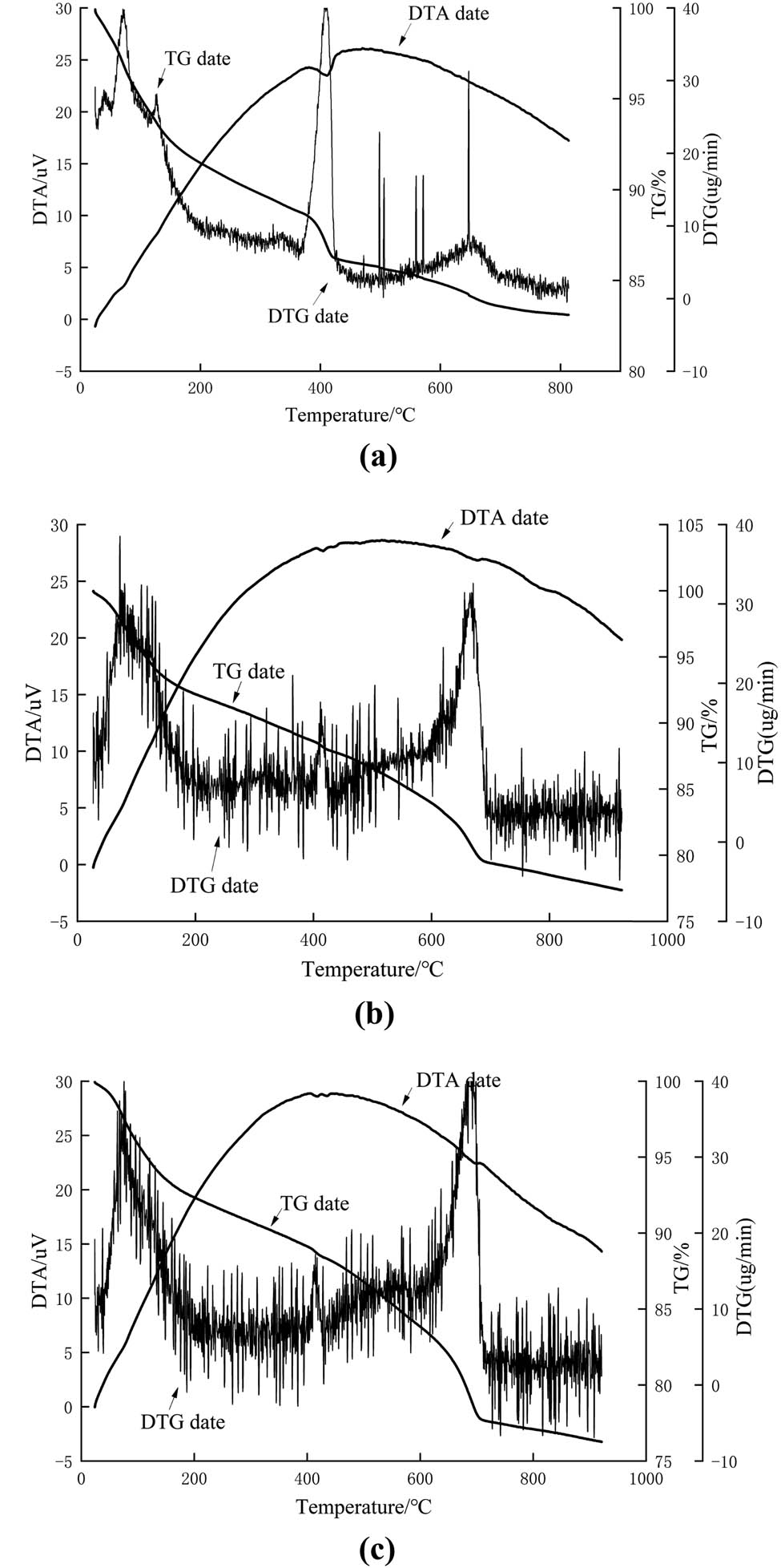
Comprehensive thermal analysis diagram: (a) 0 freeze–thaw cycles; (b) 200 freeze–thaw cycles in chlorine solution; and (c) 200 freeze–thaw cycles in the sulfate solution.
In summary, the freeze–thaw damage of concrete in the salt solution was the combined effect of the expansion pressure of the freeze–thaw erosion product, the crystallization pressure of the salt solution, and the frost heave pressure of the fresh water. Under the influence of this, the surface cracks of the concrete appeared like net, and the erosion occurred, resulting in a decrease in physical properties of concrete. As the freeze–thaw cycle progresses, the damage gradually deepened, eventually the aggregates were exposed and the concrete broke.
3.2 Deterioration of concrete durability
3.2.1 Deterioration law
The life of concrete was reduced in the salt solution after the freezing and thawing cycles, which is essentially due to the damage of concrete with the freezing and thawing cycles and the decrease of internal compactness.
The mass loss of concrete after freezing and thawing cycles is shown in Figure 5. It can be seen that the mass loss of concrete in the chlorine solution and sulfate solution increased with the increase of freezing and thawing cycles, which means that the performance of concrete gradually deteriorated with the increase of freezing and thawing cycles, and its external damage was gradually increased. In addition, the mass loss of concrete in the chloride solution was greater than that in the sulfate solution, and the mass loss of concrete increased with the increase of chloride concentration. After 150 freezing and thawing cycles, the mass loss of concrete in the sulfate solution showed a greater degree of external erosion, and the mass loss exceeded that in the chloride solution.
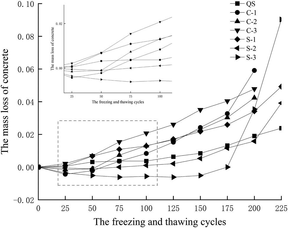
Mass loss of concrete.
In this experiment, the relative dynamic elastic modulus was used as the concrete performance index, and the damage degree D n expressed by the relative dynamic elastic modulus was used to express the damage degree of the concrete [28], as shown in equation (1):
where
The damage degree D n after freezing and thawing cycles is presented in Table 8 and Figure 6. It can be seen that the damage degree D n increased with the increase of freezing and thawing cycles, which means that the internal damage of concrete increased with the increase of freezing and thawing cycles. The damage degree of concrete in different solutions was different. The damage degree D n in the chloride salt solution increased linearly, and the damage rate was basically unchanged. The damage degree D n in the sulfate solution first increased linearly and then accelerated.
Damage degree D n after freezing and thawing cycles
| Number of freeze–thaw cycles | Damage degree (D n ) | ||||||
|---|---|---|---|---|---|---|---|
| QS | C-1 | C-2 | C-3 | S-1 | S-2 | S-3 | |
| 25 | 0.007296 | 0.048108 | 0.033898 | 0.037088 | 0.016659 | 0.008076 | 0.002771 |
| 50 | 0.046968 | 0.091079 | 0.10536 | 0.092033 | 0.024988 | 0.062233 | 0.028176 |
| 75 | 0.056544 | 0.154134 | 0.138342 | 0.14011 | 0.054604 | 0.07981 | 0.056813 |
| 100 | 0.075239 | 0.185427 | 0.179569 | 0.174451 | 0.122166 | 0.091686 | 0.088684 |
| 125 | 0.108527 | 0.200841 | 0.211177 | 0.180861 | 0.130958 | 0.115439 | 0.133487 |
| 150 | 0.126767 | 0.217188 | 0.226752 | 0.224817 | 0.151782 | 0.137292 | 0.184758 |
| 175 | 0.153671 | 0.232135 | 0.26798 | 0.291667 | 0.160574 | 0.190974 | 0.288684 |
| 200 | 0.179207 | 0.257823 | 0.306459 | 0.34478 | 0.21888 | 0.24133 | 0.317321 |
| 225 | 0.227542 | 0.40822 | 0.459459 | 0.419872 | 0.33503 | 0.355819 | 0.376443 |
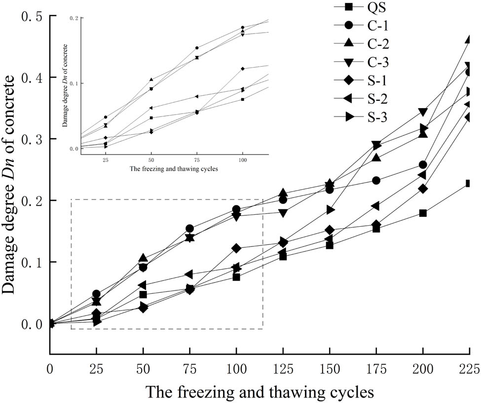
Damage degree D n of concrete.
Before 150 freezing and thawing cycles, the damage degree of concrete in the chloride solution was greater than that in the sulfate solution and fresh water. The loss of elastic modulus of concrete in the chloride solution was 1.2–1.6 times that of in the sulfate solution. After 150 freezing and thawing cycles, the damage degree of concrete in the sulfate solution increased rapidly, which was greater than that in the chloride solution.
To further explain the destruction mechanism of concrete in the salt solution environment, the ionic reaction in concrete was analyzed from the basic chemistry. The negative electric charge particles (Cl− and
3.2.2 Nuclear magnetic resonance spectrum analysis
The nuclear magnetic resonance signal was processed according to the principle of nuclear magnetic resonance [35,36], and the nuclear magnetic resonance T2 spectrum of concrete after freezing and thawing cycles was obtained, as shown in Figure 7. It can be seen that the T2 relaxation time value of the concrete without freezing and thawing cycles was smaller than that after freezing and thawing cycles (the T2 relaxation time represents the energy level transition time of all hydrogen atoms in the pore, and the larger the pore size, the more the hydrogen atoms and the longer the relaxation time). In addition, the concrete without freezing and thawing cycles had a significant single peak, and the single peak value was lower than that after freezing and thawing cycles. The single peak value of concrete in fresh water after 200 freezing and thawing cycles was significantly larger than that without freezing and thawing cycles, and the single peak value shifted to the right at the relaxation time, which means that the internal pores of the concrete were developing in the direction of large pores, but the moving value was smaller than that of concrete in the salt solution. Therefore, it can be seen that the freeze–thaw damage of the concrete in the salt solution was greater than that in fresh water.
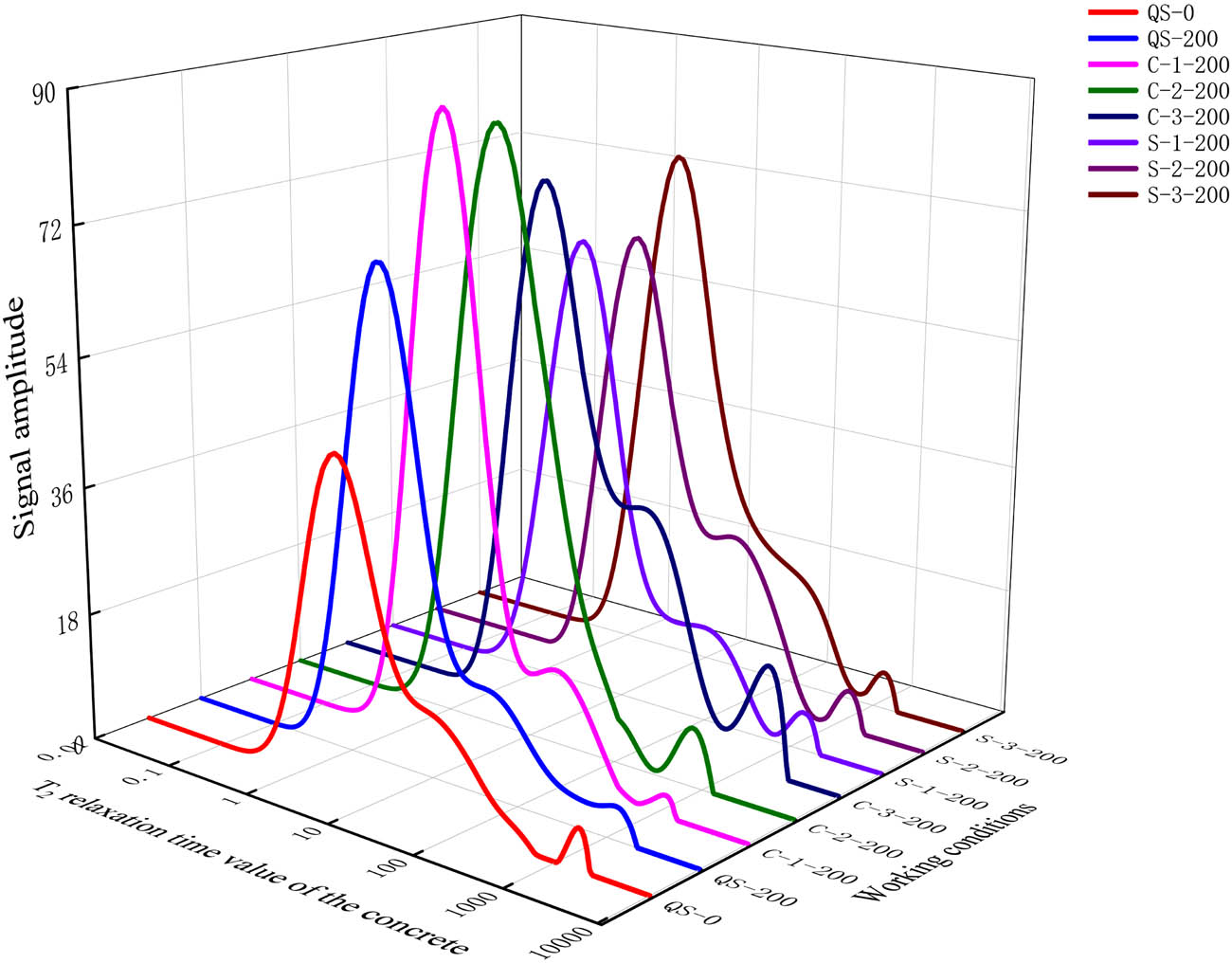
Nuclear magnetic resonance T2 spectrum.
The pores inside the concrete were extremely small and could be approximated as a spherical shape. In addition, the T2 relaxation time of concrete was directly proportional to the pore diameter, the relationship between the relaxation time and the pore diameter can be expressed by equation (2):
where
According to equation (2), the T2 spectrum of concrete could be transformed into the pore size distribution of concrete. According to Wu Zhongwei’s concrete pore type classification theory [37], it can be known that pore radius less than 0.02 μm was harmless pore, pore radius between 0.02 and 0.05 μm was less harmful pore, pore radius between 0.05–0.20 μm was harmful pore, and pore radius greater than 0.20 μm was seriously harmful pore. The pore size proportion of concrete after freezing and thawing cycles can be obtained, as shown in Figure 8, and the difference in pore size proportion of concrete after freezing and thawing cycles is shown in Figure 9.
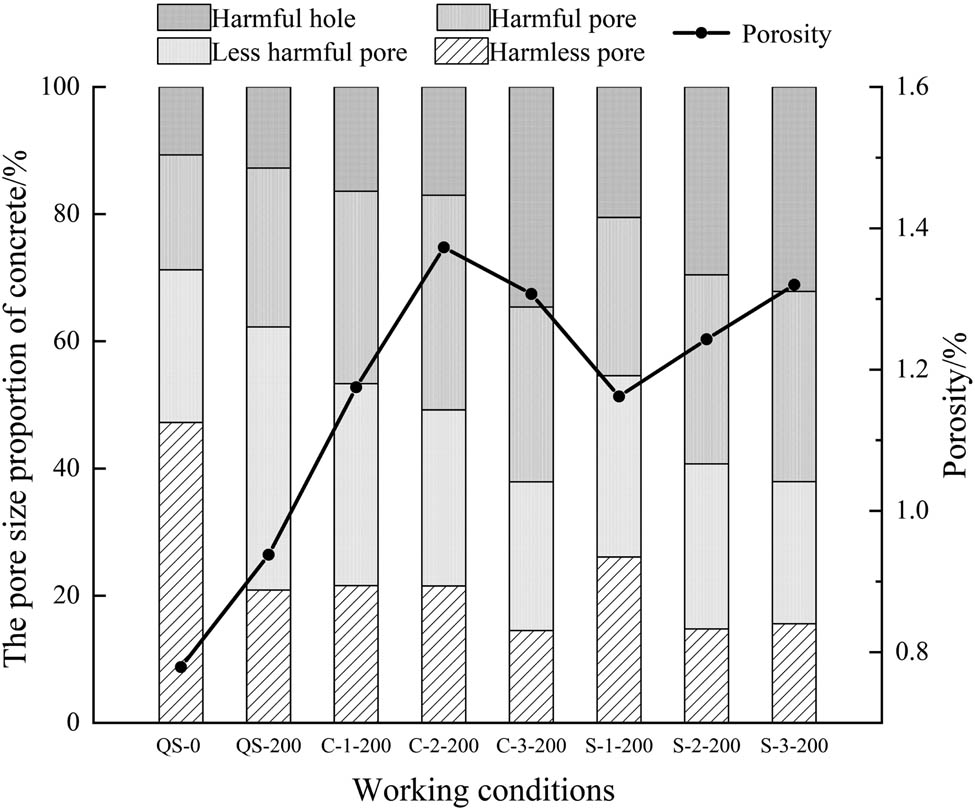
Pore size proportion of concrete after freezing and thawing cycles.
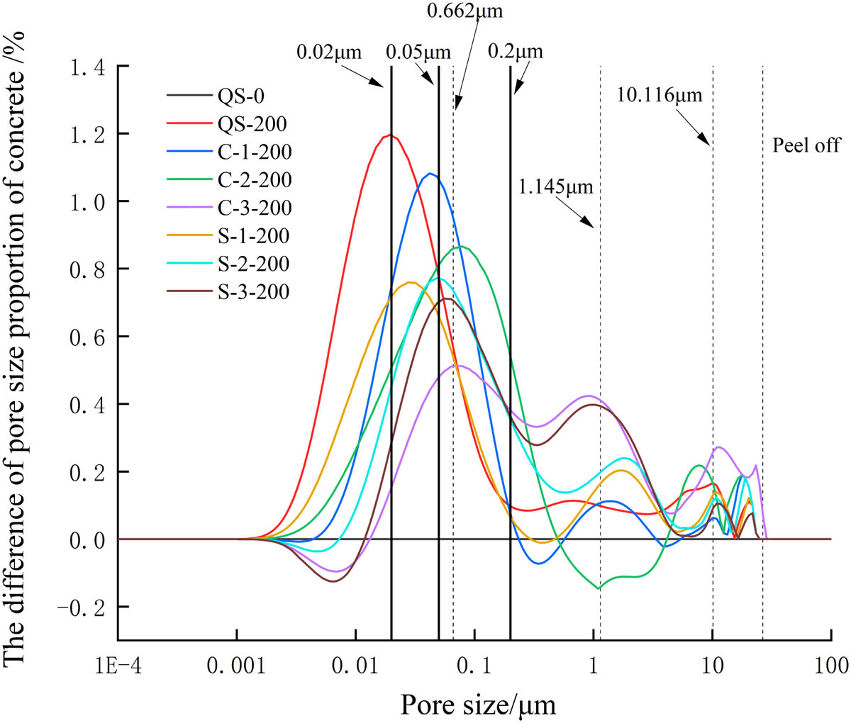
Difference of pore size proportion of concrete after freezing and thawing cycles.
Figure 9 shows that the pore size was mainly concentrated between 0.001 and 23.27 μm after 200 freezing and thawing cycles. The pores of concrete in fresh water after freezing and thawing were mainly harmless pores and less harmful pores, the main peak of the difference in pore size proportion was in the harmless pore area, and these were no obvious secondary peaks. The pore size of concrete in the salt solution was larger than that in fresh water, the main peak of the difference of pore size proportion shifted to the harmful pore area, and the secondary peak and third peak appeared in the seriously harmful pore area. The transfer range of the main peak of the difference of pore size proportion increased with the increase of the salt solution concentration, and the porosity of concrete in the salt solution after freezing and thawing cycles was greater than that without freezing and thawing cycles and greater than that in fresh water after freezing and thawing cycles. This showed that concrete damage in the salt solution was larger than that in fresh water, and it increased with the increase of the salt solution concentration.
The main peak position of the difference of pore size proportion in the chloride solution was slightly to the right than that in the sulfate solution, and the secondary peak and the third peak position were to the right and the peak values were lower. This situation can be explained from the ion reaction theory and the Goldschmidt radius: the contact radius of Cl− is smaller than
The porosity decreased with the increase of the salt solution concentration. It is because that with the increase of the salt solution concentration, the Friedel salt formed by the reaction of the higher concentration of Cl− ions with the cement paste further separated the cement paste from the aggregate.
In addition, Figure 9 shows that when the pore diameter of concrete exceeded the peak, the pore diameter changed rapidly to the next peak. Therefore, the pore diameter at the peak position can be regarded as the limiting pore diameter (the limiting pore diameter is the minimum pore diameter when the concrete was frozen in the salt solution). The limiting pore diameter deteriorated as the concrete froze, and the concrete will be eroded and damaged when the pore diameter of the concrete exceeded the final limiting pore diameter. The main peak position, the second peak position, and the third peak position of the difference of pore size proportion in different salt solution environment were similar. Therefore, the concrete in different salt solution environment had the same limiting pore diameters. Fitting the pore diameters of the main peak, the secondary peak and the third peak of concrete in different salt solution, the limiting pore diameters were 0.0662, 1.145, and 10.116 μm, respectively.
3.3 Life evaluation of concrete in salt solution after freeze–thaw cycles
Concrete is a multidirectional nonuniform material, and so the freeze–thaw damage of concrete is also multidirectional random. Therefore, the life evaluation of concrete in the salt solution after freeze–thaw cycles should be carried out from the perspective of probability theory [38].
Weibull distribution can use probability values to infer distribution parameters [39], and it is widely used in data processing of various life tests and the design of strength failure distribution functions. In this article, Weibull distribution was used as the theoretical basis of concrete life evaluation, and the life evaluation model was established through the least-square method.
Assuming that the freeze–thaw cycle life of concrete (N) conforms to the Weibull distribution, the three major influencing parameters (scale, shape, and position parameters) of the Weibull distribution can be used to obtain the concrete performance degradation distribution, which can ultimately evaluate the life of concrete in the salt solution after freezing and thawing cycles. The Weibull distribution of freeze–thaw cycle life of concrete (N) was established according to the three-parameter model, as shown in equation (3):
where
The concrete has a relative maximum life before freeze–thaw cycle, and its values is greater than or equal to 0, so that
After the freeze–thaw cycles, the relative maximum life showed the decreasing trend, until the relative maximum life was reduced to 0, and the damage degree D n = 1.
Carry out the Weibull transform of equation (4):
Let
According to Table 8 and equations (4)–(6), the Weibull calculations were performed to obtain the Weibull parameter b and c of concrete life in the salt solution after freezing and thawing cycles, as shown in Figure 10 and Table 9. The regression relationship coefficient R 2 was greater than 0.9. The parameters in the corresponding test were brought into the Weibull regression equation of concrete life in the salt solution after freezing and thawing cycles, and the evaluation life of concrete in salt solution after freeze–thaw cycles were done.
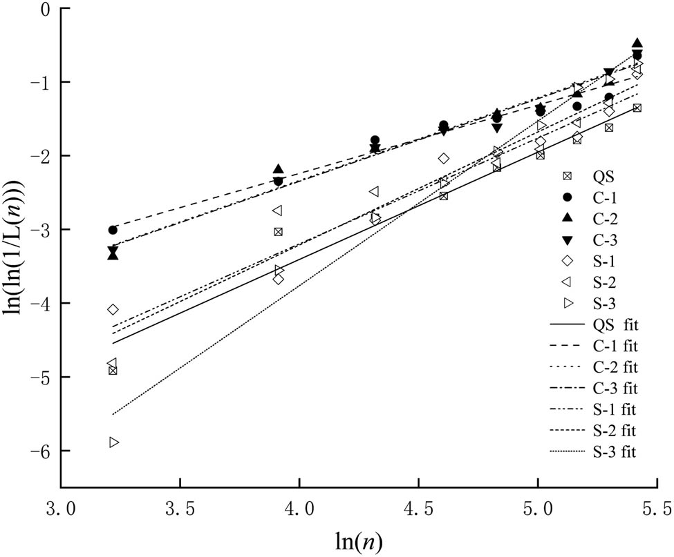
Weibull distribution life linear regression line.
Webb regression results of concrete life
| Operating condition | b | c | R 2 |
|---|---|---|---|
| QC | 1.3662 | −9.2781 | 0.9711 |
| C-1 | 0.9276 | −5.9517 | 0.9501 |
| C-2 | 1.1231 | −6.8284 | 0.9602 |
| C-3 | 1.12 | −6.6884 | 0.9792 |
| S-1 | 1.4355 | −8.9387 | 0.9540 |
| S-2 | 1.5337 | −9.3471 | 0.9292 |
| S-3 | 2.2335 | −12.6975 | 0.9809 |
In addition, the average number of freeze–thaw cycles in the northwestern region was 8.8 [40], and the safe service life of concrete in the salt solution was obtained after freezing and thawing cycles. Table 10 presents the evaluation life and the safe service life of concrete in the salt solution after freezing and thawing cycles. It can be seen that Cl− and
Evaluation life and safe service life of concrete in the salt solution after freezing and thawing cycles
| Operating condition | Evaluation life (time) | Safe service life of concrete (year) |
|---|---|---|
| QS | 544 | 62 |
| C-1 | 296 | 33 |
| C-2 | 240 | 26 |
| C-3 | 215 | 24 |
| S-1 | 317 | 36 |
| S-2 | 286 | 32 |
| S-3 | 217 | 24 |
4 Conclusion
The freeze–thaw damage of concrete in the salt solution is the combined effect of the expansion pressure of the freeze–thaw erosion product, the crystallization pressure of the salt solution, and the frost heave pressure of the fresh water.
The damage degree increases with the increase of freezing and thawing cycles. Before 150 freezing and thawing cycles, the damage degree of concrete in the chloride solution is greater than that in the sulfate solution and fresh water. After 150 freezing and thawing cycles, the damage degree of concrete in the sulfate solution is greater than that in the chloride solution.
The pore size of concrete in the salt solution is larger than that in fresh water, the main peak of the difference in pore size proportion shifts to the harmful pore area, and the secondary peak and third peak appear in the seriously harmful pore area. The pore diameters of the main peak, the secondary peak and the third peak of concrete in different salt solution, and the limiting pore diameters are 0.0662, 1.145, and 10.116 μm, respectively.
The safe service life of concrete in the salt solution environment after freezing and thawing cycles is at least 42% lower than that in a fresh water environment after freezing and thawing cycles.
Acknowledgments
Thank you for all editors and reviewers.
-
Funding information: The study was carried out with the support of the research foundation of education department of inner Mongolia (NJZZ18044); the Initiation fee for doctoral degree of Inner Mongolia Agricultural University (BJ2015-2); and the general program of science foundation of inner Mongolia (2021MS05045).
-
Author contributions: Hao Li: investigation, methodology, writing – original draft preparation; Haolong Guo: writing – original draft preparation, check original draft, methodology; Yuan Zhang: visualization, check original draft, formal analysis.
-
Conflict of interest: Authors state no conflict of interest.
-
Data availability statement: All data, models, and code generated or used during the study appear in the submitted article.
References
[1] Xiaochuan, Q., L. Jiaping, S. Liang, M. Song, C. Jingshun, W. Zhenjie, et al. Research progress of concrete durability test methods and devices under the coupling effect of load and chloride ion. Materials Reports, Vol. 34, No. 3, 2020, pp. 112–121 (in Chinese).Search in Google Scholar
[2] Shujuan, Y., Y. Shuyan, C. Jialing, and L. Xila. Study on the resistance of sodium sulfate semi-soaked cement-based materials to chloride ion permeability under capillary action. Chinese Journal of Civil and Environmental Engineering (Chinese and English), Vol. 42, No. 3, 2020, pp. 133–140.Search in Google Scholar
[3] Lidong, Y., N. Ditao, J. Lei, S. Yingzhao, and F. Qiannan. Study on damage of concrete under the combined action of sulfate attack and freeze–thaw cycle. Bulletin of the Chinese Ceramic Society, Vol. 32, No. 6, 2013, pp. 1171–1176.Search in Google Scholar
[4] Jiabin, W., N. Ditao, H. Hui, and S. Zhanping. Durability degradation and corrosion mechanism of shotcrete in salt lake environment. China Civil Engineering Journal, Vol. 52, No. 06, 2019, pp. 67–80 (in Chinese).Search in Google Scholar
[5] Yue, W., A. Mingze, Y. Zirou, S. Han, and J. Wenyue. Durability of reactive powder concrete under chloride-salt freeze–thaw cycling. Materials and Structures, Vol. 50, No. 1, 2017, id. 18.10.1617/s11527-016-0878-5Search in Google Scholar
[6] Saboori, A. and A. Saboori. Application of damage mechanics to describe the behavior of concrete under fatigue and freeze–thaw processes. Dissertations & Theses – Gradworks, Vol. 29, No. 1, 2015, pp. 3–22.Search in Google Scholar
[7] An, M., Y. Wang, and Z. Yu. Damage mechanisms of ultra-high-performance concrete under freeze–thaw cycling in salt solution considering the effect of rehydration. Construction and Building Materials, Vol. 198, 2019, pp. 546–552.10.1016/j.conbuildmat.2018.11.175Search in Google Scholar
[8] Yan, L., L. Henglin, Y. Huiguang, L. Ruixue, L. Bing, and Z. Lianying. Test research on the water absorption properties of C60 concrete after freeze–thawing cycles. Concrete, Vol. 9, 2014, pp. 15–18 (in chinese).Search in Google Scholar
[9] Yuan, L.-D., D.-T. Niu, L. Jiang, Y.-Z. Sun, and Q.-N. Fei. Study on damage of concrete under the combined action of sulfate attack and freeze–thaw cycles. Bulletin of the Chinese Ceramic Society, Vol. 32, No. 06, 2013, pp. 1171–1176 (in Chinese).Search in Google Scholar
[10] Liu, Z., L. Hou, D. Deng, F. Zhang, and W. Hu. Sodium sulfate salt crystallization distress on carbonized concrete. Journal of The Chinese Ceramic Society, Vol. 45, No. 11, 2017, pp. 1621–1628 (in Chinese).Search in Google Scholar
[11] Tan, Y., H. Yu, H. Ma, Y. Zhang, and C. Wu. Study on the micro-crack evolution of concrete subjected to stress corrosion and magnesium sulfate. Construction & Building Materials, Vol. 141, 2017, pp. 453–460.10.1016/j.conbuildmat.2017.02.127Search in Google Scholar
[12] Alnahhal, M. F., U. J. Alengaram, M. Z. Jumaat, B Alsubari, M. A. Alqedra, and K. H. Mo. Effect of aggressive chemicals on durability and microstructure prop-erties of concrete containing crushed new concrete aggregate and non-traditional supplementary cementitious materials. Construction & Building Materials, Vol. 163, 2018, pp. 482–495.10.1016/j.conbuildmat.2017.12.106Search in Google Scholar
[13] Zhou, P., W. Wang, L. Zhu, H. Wang, and Y. Ai. Study on performance damage and mechanism analysis of asphalt under action of chloride salt erosion. Materials, Vol. 14, 2021, id. 3089.10.3390/ma14113089Search in Google Scholar
[14] Wang, F., X. Qin, W. Pang, and W. Wang. Performance deterioration of asphalt mixture under chloride salt erosion. Materials, Vol. 14, 2021, id. 3339.10.3390/ma14123339Search in Google Scholar
[15] Tian, S., T. Wang, C. Wang, and H. Yi. The influence of salt-frost cycles on the bond behavior distribution between rebar and recycled coarse aggregate concrete. Journal of Building Engineering, Vol. 45, 2022, id. 103568.10.1016/j.jobe.2021.103568Search in Google Scholar
[16] Tian, S., T. Wang, H. Yi, R. Zheng, Y. Liu, H. Zhai, et al. Finite element analysis on the bond behavior of steel bar in salt–frost-damaged recycled coarse aggregate concrete. Reviews on Advanced Materials Science, Vol. 60, No. 1, 2021, pp. 853–861.10.1515/rams-2021-0063Search in Google Scholar
[17] Wen, D. Study on mechanical properties and salt freezing-resistance of recycled aggregate concrete [Masters degree], Huazhong University of Science and Technology, Wuhan, 2013.Search in Google Scholar
[18] Hu, J. and J. Wu. Mechanical properties and uni-axial compression stress-strain relation of recycled coarse aggregate concrete subjected to salt-frost cycles. Construction and Building Materials, Vol. 197, No. 2, 2019, pp. 652–666.10.1016/j.conbuildmat.2018.11.213Search in Google Scholar
[19] Tian, S., W. Jin, Y. Guixin, and Z. Zhenghao. Bond behavior between recycled coarse aggregate concrete and steel bar after salt-frost cycles. Construction and Building Materials, Vol. 226, No. 11, 2019, pp. 673–685.10.1016/j.conbuildmat.2019.07.301Search in Google Scholar
[20] Tian, S., W. Jin, Z. Zhenghao, and Y. Jifeng. Bond performance of steel bar in RAC under salt-frost and repeated loading. Journal of Materials in Civil Engineering, Vol. 32, No. 9, 2020, id. 04020261–1.10.1061/(ASCE)MT.1943-5533.0003303Search in Google Scholar
[21] GB/T 50082-2009. Standard for long-term performance and durability test methods of ordinary concrete, China Building Industry Press, China Academy of Building Research, Beijing, China, 2010 (in Chinese).Search in Google Scholar
[22] Wei, L. and X. Li. NMR logging, Petroleum Industry Press, Beijing, 2011, pp. 33–49 (in chinese).Search in Google Scholar
[23] Elsharief, A., M. D. Cohen, and J. Olek. Influence of aggregate size, water cement ratio and age on the microstructure of the interfacial transition zone. Cement & Concrete Research, Vol. 33, No. 11, 2003, pp. 1837–1849.10.1016/S0008-8846(03)00205-9Search in Google Scholar
[24] Yuebo, C., L. Rui, and W. Changyi. Microstructure analysis of cement-ground slag hydration product-F salt. Journal of Water Resources and Water Transport Engineering, Vol. 1, 2001, pp. 45–49 (in Chinese).Search in Google Scholar
[25] Zongxi, W., Y. Zhanquan, H. Liang, W. Hanhan, and L. Zimei. Effect of nano-SiO2 on the corrosion resistance and corrosion life of concrete. Journal of Building Materials, Vol. 24, No. 4, 2021, pp. 744–773 (in Chinese).Search in Google Scholar
[26] Zuqi, W. Thermal analysis curve Atlas, Metallurgical Industry Press, Beijing, 1978 (in Chinese).Search in Google Scholar
[27] Nanru, Y. and Y. Haiwen. Inorganic non-metallic materials atlas manual, Wuhan University of Technology Press, Wuhan, 2000 (in Chinese).Search in Google Scholar
[28] Cundong, X., Z. Peng, L. Haidong, W. Yan, L. Zhen, and G. Fengyou. Life prediction of concrete buildings in irrigated areas based on Weibull distribution. Bulletin of the Chinese Ceramic Society, Vol. 284, No. 5, 2020, pp. 136–143 (in Chinese).Search in Google Scholar
[29] Ying, M. The effect of alkali metal sulfate on the early hydration and hardening of Portland cement [Masters degree], Chongqing University, Chongqing, China, 2017 (in Chinese).Search in Google Scholar
[30] Yuanzhang, C., G. Liping, Z. Wenjie, Z. Jian, and X. Xiaoli. Failure mechanism of cement-based materials subjected to the interaction between chloride and sulfate-a review. Materials Guide, Vol. 32, No. 23, 2018, pp. 4142–4149 (in Chinese).Search in Google Scholar
[31] Zongshou, L. Cementitious materials science, Wuhan University of Technology Press, 2014 (in Chinese).Search in Google Scholar
[32] Qian, H., W. Chong, Z. Liang, and Z. Min. Effect of nano-SiO2 on the sulfate resistance of cement mortar under partial immersion. Journal of Building Materials, Vol. 22, No. 6, 2019, pp. 978–985 (in Chinese).Search in Google Scholar
[33] Qianqing, X. Research on ionic radius. Journal of Hainan Normal University (Natural Science Edition), Vol. 3, 2001, pp. 68–75 (in Chinese).Search in Google Scholar
[34] Gaifei, P., L. Yefeng, and H. Tingyu. Current status of field test technology for concrete surface layer permeability at home and abroad: Summary. See: Xing Feng. Durability and design methods of concrete structures in coastal areas, People Communications Press, Beijing, 2004, pp. 287–296 (in Chinese).Search in Google Scholar
[35] Haibo, L., Z. Juyi, and G. Hekun. Research on the conversion method of pore radius distribution by nuclear magnetic resonance T2 spectrum. Journal of Spectroscopy, Vol. 25, No. 2, 2008, pp. 273–280 (in Chinese).Search in Google Scholar
[36] Xiaoxiao, W., S. Xiangdong, W. Hailong, G. Chu, and Z. Tong. Nuclear magnetic resonance analysis of freeze–thaw damage in natural pumice concrete. Materiales de Construcción, Vol. 66, No. 322, 2016, p. e087.10.3989/mc.2016.09014Search in Google Scholar
[37] Zhongwei, W. and L. Huizhen. High performance concrete, China Railway Press, Beijing, 1999, pp. 41–43 (in Chinese).Search in Google Scholar
[38] Tian, L. and L. Xila. Analysis and design of concrete structure durability, Science Press, Beijing, 1999, pp. 134–165 (in Chinese).Search in Google Scholar
[39] Skiadas, C. H. and C. Skiadas. Relation of the Weibull shape parameter with the healthy life years lost estimates: Analytical derivation and estimation from an extended life table, Demography of Population Health, Aging and Health Expenditures, Springer, Cham, Switzerland, 2020.10.1007/978-3-030-44695-6_2Search in Google Scholar
[40] Jinyu, L. Durability design and construction guidelines for concrete structures in freeze–thaw environments. Cement-based Materials Proceedings of the 2003 Academic Annual Meeting of the Chinese Ceramic Society, Vol. 2, 2003 (in Chinese).Search in Google Scholar
© 2022 Hao Li et al., published by De Gruyter
This work is licensed under the Creative Commons Attribution 4.0 International License.
Articles in the same Issue
- Review Articles
- State of the art, challenges, and emerging trends: Geopolymer composite reinforced by dispersed steel fibers
- A review on the properties of concrete reinforced with recycled steel fiber from waste tires
- Copper ternary oxides as photocathodes for solar-driven CO2 reduction
- Properties of fresh and hardened self-compacting concrete incorporating rice husk ash: A review
- Basic mechanical and fatigue properties of rubber materials and components for railway vehicles: A literature survey
- Research progress on durability of marine concrete under the combined action of Cl− erosion, carbonation, and dry–wet cycles
- Delivery systems in nanocosmeceuticals
- Study on the preparation process and sintering performance of doped nano-silver paste
- Analysis of the interactions between nonoxide reinforcements and Al–Si–Cu–Mg matrices
- Research Articles
- Study on the influence of structural form and parameters on vibration characteristics of typical ship structures
- Deterioration characteristics of recycled aggregate concrete subjected to coupling effect with salt and frost
- Novel approach to improve shale stability using super-amphiphobic nanoscale materials in water-based drilling fluids and its field application
- Research on the low-frequency multiline spectrum vibration control of offshore platforms
- Multiple wide band gaps in a convex-like holey phononic crystal strip
- Response analysis and optimization of the air spring with epistemic uncertainties
- Molecular dynamics of C–S–H production in graphene oxide environment
- Residual stress relief mechanisms of 2219 Al–Cu alloy by thermal stress relief method
- Characteristics and microstructures of the GFRP waste powder/GGBS-based geopolymer paste and concrete
- Development and performance evaluation of a novel environmentally friendly adsorbent for waste water-based drilling fluids
- Determination of shear stresses in the measurement area of a modified wood sample
- Influence of ettringite on the crack self-repairing of cement-based materials in a hydraulic environment
- Multiple load recognition and fatigue assessment on longitudinal stop of railway freight car
- Synthesis and characterization of nano-SiO2@octadecylbisimidazoline quaternary ammonium salt used as acidizing corrosion inhibitor
- Perforated steel for realizing extraordinary ductility under compression: Testing and finite element modeling
- The influence of oiled fiber, freeze-thawing cycle, and sulfate attack on strain hardening cement-based composites
- Perforated steel block of realizing large ductility under compression: Parametric study and stress–strain modeling
- Study on dynamic viscoelastic constitutive model of nonwater reacted polyurethane grouting materials based on DMA
- Mechanical behavior and mechanism investigation on the optimized and novel bio-inspired nonpneumatic composite tires
- Effect of cooling rate on the microstructure and thermal expansion properties of Al–Mn–Fe alloy
- Research on process optimization and rapid prediction method of thermal vibration stress relief for 2219 aluminum alloy rings
- Failure prevention of seafloor composite pipelines using enhanced strain-based design
- Deterioration of concrete under the coupling action of freeze–thaw cycles and salt solution erosion
- Creep rupture behavior of 2.25Cr1Mo0.25V steel and weld for hydrogenation reactors under different stress levels
- Statistical damage constitutive model for the two-component foaming polymer grouting material
- Nano-structural and nano-constraint behavior of mortar containing silica aggregates
- Influence of recycled clay brick aggregate on the mechanical properties of concrete
- Effect of LDH on the dissolution and adsorption behaviors of sulfate in Portland cement early hydration process
- Comparison of properties of colorless and transparent polyimide films using various diamine monomers
- Study in the parameter influence on underwater acoustic radiation characteristics of cylindrical shells
- Experimental study on basic mechanical properties of recycled steel fiber reinforced concrete
- Dynamic characteristic analysis of acoustic black hole in typical raft structure
- A semi-analytical method for dynamic analysis of a rectangular plate with general boundary conditions based on FSDT
- Research on modification of mechanical properties of recycled aggregate concrete by replacing sand with graphite tailings
- Dynamic response of Voronoi structures with gradient perpendicular to the impact direction
- Deposition mechanisms and characteristics of nano-modified multimodal Cr3C2–NiCr coatings sprayed by HVOF
- Effect of excitation type on vibration characteristics of typical ship grillage structure
- Study on the nanoscale mechanical properties of graphene oxide–enhanced shear resisting cement
- Experimental investigation on static compressive toughness of steel fiber rubber concrete
- Study on the stress field concentration at the tip of elliptical cracks
- Corrosion resistance of 6061-T6 aluminium alloy and its feasibility of near-surface reinforcements in concrete structure
- Effect of the synthesis method on the MnCo2O4 towards the photocatalytic production of H2
- Experimental study of the shear strength criterion of rock structural plane based on three-dimensional surface description
- Evaluation of wear and corrosion properties of FSWed aluminum alloy plates of AA2020-T4 with heat treatment under different aging periods
- Thermal–mechanical coupling deformation difference analysis for the flexspline of a harmonic drive
- Frost resistance of fiber-reinforced self-compacting recycled concrete
- High-temperature treated TiO2 modified with 3-aminopropyltriethoxysilane as photoactive nanomaterials
- Effect of nano Al2O3 particles on the mechanical and wear properties of Al/Al2O3 composites manufactured via ARB
- Co3O4 nanoparticles embedded in electrospun carbon nanofibers as free-standing nanocomposite electrodes as highly sensitive enzyme-free glucose biosensors
- Effect of freeze–thaw cycles on deformation properties of deep foundation pit supported by pile-anchor in Harbin
- Temperature-porosity-dependent elastic modulus model for metallic materials
- Effect of diffusion on interfacial properties of polyurethane-modified asphalt–aggregate using molecular dynamic simulation
- Experimental study on comprehensive improvement of shear strength and erosion resistance of yellow mud in Qiang Village
- A novel method for low-cost and rapid preparation of nanoporous phenolic aerogels and its performance regulation mechanism
- In situ bow reduction during sublimation growth of cubic silicon carbide
- Adhesion behaviour of 3D printed polyamide–carbon fibre composite filament
- An experimental investigation and machine learning-based prediction for seismic performance of steel tubular column filled with recycled aggregate concrete
- Effects of rare earth metals on microstructure, mechanical properties, and pitting corrosion of 27% Cr hyper duplex stainless steel
- Application research of acoustic black hole in floating raft vibration isolation system
- Multi-objective parametric optimization on the EDM machining of hybrid SiCp/Grp/aluminum nanocomposites using Non-dominating Sorting Genetic Algorithm (NSGA-II): Fabrication and microstructural characterizations
- Estimating of cutting force and surface roughness in turning of GFRP composites with different orientation angles using artificial neural network
- Displacement recovery and energy dissipation of crimped NiTi SMA fibers during cyclic pullout tests