Perforated steel for realizing extraordinary ductility under compression: Testing and finite element modeling
-
Yingwu Zhou
 ,
Xiaoxu Huang
,
Xiaoxu Huang

Abstract
One key obstacle restricting the application of fiber-reinforced polymer (FRP) bars from being used as reinforcement in structural concrete is the significantly reduced ductility because FRP under tension is linear elastic up to brittle rupture at small strain. Recently, a new structural concept, compression yielding (CY), has been proposed as a way to overcome the insufficient ductility of concrete structures reinforced with FRP bars or other non-ductile materials. In the CY structural system, the compression-zone of normal concrete is replaced by a ductile material within the plastic hinge. This enables the flexural deformation to be achieved by the compressive deformation of CY material rather than a tensile deformation of longitudinal reinforcing bars. To this end, an ideal CY material requires strength to be maintained during the extraordinarily large deformation process. This study tries to identify methods for developing this kind of CY material by designing and optimizing perforations inside a mild steel block. The effects of key parameters, including ratio, diameter, and arrangement of perforations on the stiffness, strength, and ductility of CY materials were experimentally investigated. In addition, a finite element (FE) model was developed to predict the behavior of the proposed CY material.
1 Introduction
The durability of reinforced concrete (RC) structures in coastal environments has attracted the attention of the research community [1], with special emphasis given to the corrosion of steel reinforcement, which is one of the most detrimental factors in the degradation of structural performance [2,3]. Due to the advantages of corrosion resistance, lightweight, high strength, fatigue resistant, convenient construction, good chemical stability, and low maintenance costs, fiber-reinforced polymers (FRPs) have been adopted in terms of strengthening degraded RC structures and reinforcing new RC structures [4,5,6]. However, using FRP bars as reinforcement in concrete structures is subjected to a significant drawback, namely, the remarkably reduced ductility. This is because the tensile strain capacity of FRP bars is low, and the linear elastic stress–strain behavior up to rupture without yielding normally results in the failure mode of concrete crush [7]. Naaman [8] says that “unless ductility requirements are satisfied, FRP materials cannot be used reliably in structural engineering applications.”
Recently, though, the introduction of an innovative structural concept, compression yielding (CY), is attempting to counteract the ductility defects of RC structures with FRP bars used as the main reinforcement [7,9]. In a CY concrete beam, the CY block is made from extraordinary ductile material and replaces the normal concrete on the compression side within the plastic hinge zone, as shown in Figure 1(a). In the CY structural system, the large ductile flexural deformation comes from the compressive deformation of the CY zone rather than the tensile yielding of longitudinal reinforcement. Previous experiments have shown the ability of this new structural system to significantly enhance the ductility of members with non-ductile longitudinal reinforcement, e.g., carbon FRP (CFRP), as depicted in Figures 1(b) and (c). Because the ductile deformation of the CY structure depends on the deformation capacity of the CY block, the CY-material used must reach enormous ductility while maintaining its strength. Much information about the CY structural system can be found in the literature [7,9,10,11].
![Figure 1
CY structural system [7,11]: (a) CY beam with non-ductile reinforcement, (b) responses of test specimens, and (c) load vs mid-span displacement.](/document/doi/10.1515/rams-2022-0021/asset/graphic/j_rams-2022-0021_fig_001.jpg)
Generally, two methods can be used to develop the CY material. The first is the cementitious-based approach, which uses slurry infiltrated fiber concrete (SIFCON) to replace the concrete in the plastic hinge zone to form the so-called CY block. Although SIFCON can provide some ductility for concrete beams with non-ductile longitudinal reinforcement [12], SIFCON can hardly reach the level of extraordinary ductility demanded by CY material in some situations [11]. The second is the metallic-based method. Using graphene to reinforce the metal matrix, which not only enhances the strength of the composite materials but also greatly improves the ductility [13]. However, when proposed for large-scale applications, the metallic-based method carries high costs and can be considered to be an uneconomical and impractical CY structural system.
Wu et al. [11] and Liu et al. [14] noted that low carbon steel blocks with well-designed perforations can be an ideal material for the blocks used in a CY structural system. The low carbon steel has high ductility, and the perforations can further enhance the ductility as well as adjust the strength. Wu et al. [11] confirmed this to be effective using perforated SIFCON to reach the desired ductility of both CY material and CY structural beams. Although the material properties of steel are well known, knowledge of the design and material properties of perforated steel blocks remain unknown, especially when it comes to reaching extraordinary ductility while maintaining strength simultaneously. Therefore, it is necessary to develop and optimize the design of perforated steel blocks by identifying the key parameters involved and evaluating the resulting mechanical properties.
In this article, the perforated steel block is developed to provide sufficient ductility and with the strength maintained (within a certain range) for the CY structural system. To this end, first, critical parameters were identified by experimentally examining their effects on the material properties and failure modes on the designed perforated steel blocks. The parameters considered were hole arrangement, void ratio, hole diameter, and hole arrangement shape at specimen ends. Then, the finite element (FE) model was developed to further understand the design and mechanical behavior of the perforated steel blocks.
2 Experiment program
2.1 Specimen design
All the specimens involved in this test were made from low-carbon steel Q235A (yield strength = 235 MPa), including two solid cuboid specimens and 10 cuboid steel blocks with perforations, as shown in Figure 2. The dimensions (length × width × height) of the two solid cuboids (Figure 2(a)) were 25 mm3 × 25 mm3 × 50 mm3 and 25 mm3 × 25 mm3 × 100 mm3, corresponding to the aspect ratios of 2.0 and 4.0, respectively. The main purpose of these reference specimens was to obtain the yield strength of the material through the compression test and to validate the FE model from a material behavior point of view. The 10 perforated specimens were designed with the same global geometrical dimensions (Figure 2[a]), i.e., 50 mm in length, 50 mm in width, and 150 mm in height, corresponding to a height-to-width ratio of 3.0. The main test variables were the diameter of a hole (D), the horizontal distance of hole (C), the vertical distance of hole (H), void ratio (r = D/C), hole pattern coefficient (h = H/C), and wedge pattern of holes at the block’s end (ϕ = m/n), as illustrated in Figures 2(b) and (c). The details of the test specimens are shown in Table 1. The two solid specimens were labeled as CB1 and CB2, respectively, and the ten perforated specimens were named CY1–CY10.

Test specimens: (a) CY block, (b) 3D view, and (c) dimensions.
Specimen details
| Spec. ID | Dimensionsa (mm) | Hole diameter D (mm) | Hole distance C (mm) | Hole distance H (mm) | Void ratio r (D/C) | Hole layout factor at end ϕ (m/n) | Hole layout coefficient h (H/C) |
|---|---|---|---|---|---|---|---|
| CB1 | 25 × 25 × 50 | — | — | — | — | — | |
| CB2 | 25 × 25 × 100 | — | — | — | — | — | |
| CY1 | 50 × 50 × 150 | 8.75 | 12.5 | 10.825 | 0.7 | 2/4 | 0.866 |
| CY2 | 50 × 50 × 150 | 8 | 10 | 10 | 0.8 | 2/5 | 1.0 |
| CY3 | 50 × 50 × 150 | 5 | 6.25 | 6.25 | 0.8 | 3/8 | 1.0 |
| CY4 | 50 × 50 × 150 | 17.5 | 25 | 21.65 | 0.7 | 2/2 | 0.866 |
| CY5 | 50 × 50 × 150 | 20 | 25 | 21.65 | 0.8 | 2/2 | 0.866 |
| CY6 | 50 × 50 × 150 | 22.5 | 25 | 21.65 | 0.9 | 2/2 | 0.866 |
| CY7 | 50 × 50 × 150 | 10 | 12.5 | 10.825 | 0.8 | ¼ | 0.866 |
| CY8 | 50 × 50 × 150 | 10 | 12.5 | 10.825 | 0.8 | 2/4 | 0.866 |
| CY9 | 50 × 50 × 150 | 10 | 12.5 | 10.825 | 0.8 | ¾ | 0.866 |
| CY10 | 50 × 50 × 150 | 10 | 12.5 | 10.825 | 0.8 | 4/4 | 0.866 |
Note: a = length × width × height; C = hole distance in horizontal direction; H = hole distance in vertical direction; m = the hole number at the first layer; n = maximum values of the hole number at one layer.
2.2 Material properties
Figure 3 shows the uniaxial compressive test results of two solid steel blocks, and the yield loads of CB1 and CB2 were both 173 kN. The yield strength of the two solid blocks was consistent, and their average value (277 MPa) was viewed as the (compressive) yield strength of the material used in the FE simulation. For specimen CB1, loading was terminated at 500 kN, corresponding to a compressive displacement of 13 mm. A bulging segment was observed near the center of the block at that time. For specimen CB2, the applied load was terminated at 400 kN, corresponding to a compressive displacement of 18 mm. An obvious bending was observed because of the uneven compressive deformation indicating that, at a larger aspect ratio, the load-carrying capacity would deteriorate because an instability failure occurred.
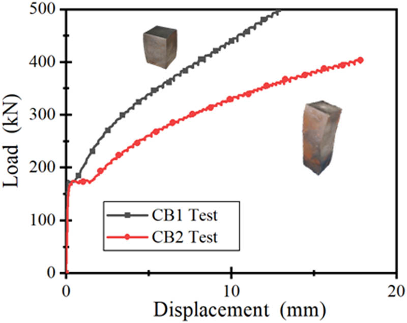
Compression test curve of the solid test block.
2.3 Test setup and instrumentations
A 3,000 kN universal testing system was used to apply the uniaxial compressive loading. The static compressive load was applied in a displacement control mode at a rate of 2 mm·min−1. In the whole loading process, a digital image correlation (DIC) system monitored the strain fields, and two linear variable differential transformers were used to capture the global vertical compressive deformation. The compression load was measured and recorded by a load cell. The test setup is shown in Figure 4.

Test setup: (a) loading protocol and DIC system and (b) schematic.
3 Experimental results and analyses
3.1 Failure modes and corresponding typical stress–strain responses
For the 10 perforated steel blocks tested in this study, three typical failure modes were observed, as shown in Figure 5. For type I, type II, and type III failure modes, corresponding typical stress–strain responses are seen in Figures 6(a), (b), and (c), respectively.

Three typical failure modes: (a) Type I, (b) Type II, and (c) Type III.
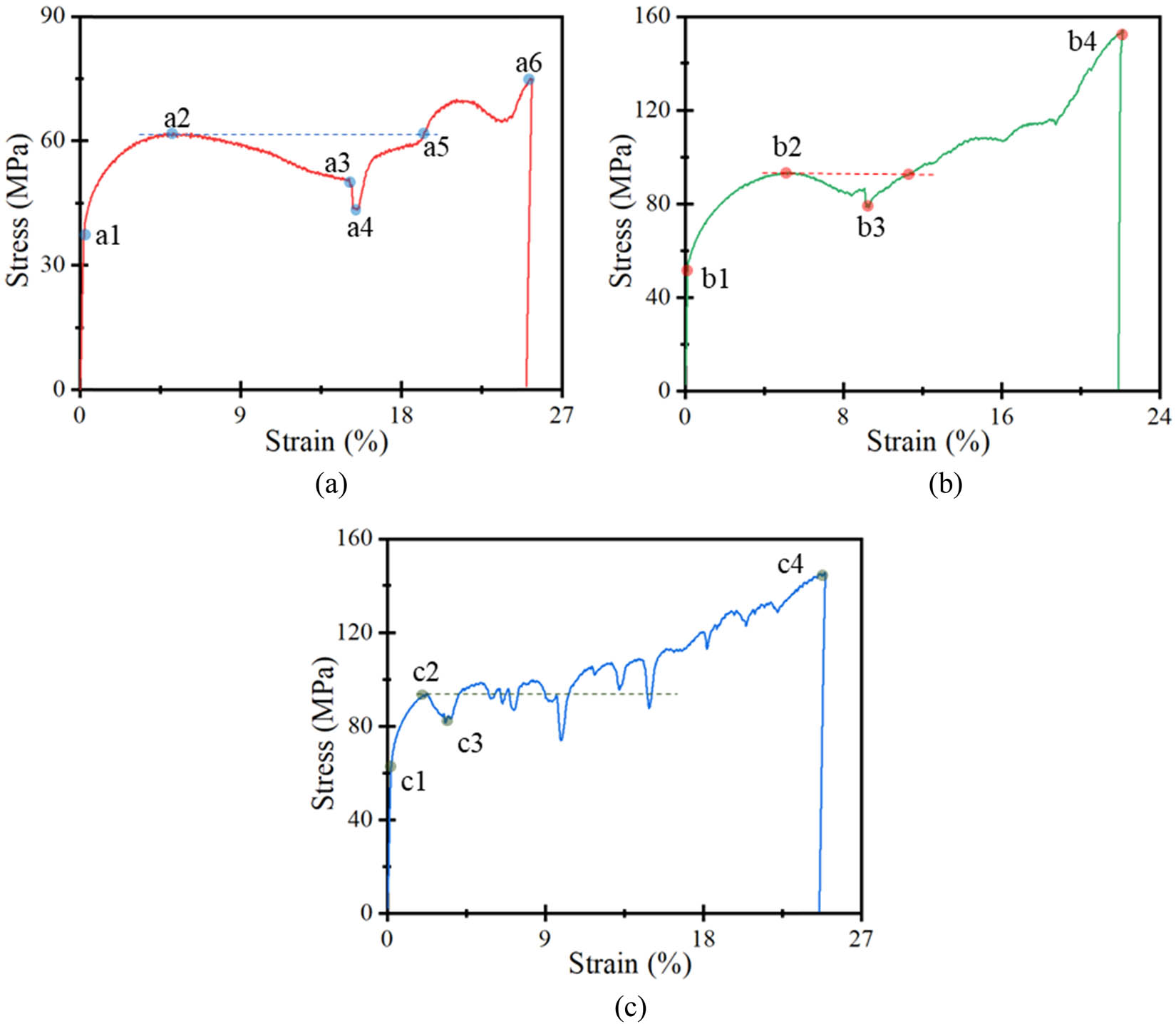
Three typical stress–strain curves corresponding to three failure modes: (a) stress–strain curve of failure mode type I, (b) stress–strain curve of failure mode type II, and (c) stress–strain curve of failure mode type III.
Type I failure mode (Figure 5(a)) resulted in enormous inelastic deformation (strain) with the stress fluctuating around the first peak stress during the whole loading process (Figure 6(a)), which was identified as the high ductile mode and ideal for CY material. For the stress–strain curve of failure mode type I, the elastic limit reached point a1, and the first peak stress after large inelastic straining occurred at point a2. Afterward, from points a2 to a3, the stress decreased moderately because of the gradual compressive buckling of the thin-walled steel skeleton after perforation. From there, a sudden and sharp drop of stress occurred until point a4, caused by the unstable buckling and squashed perforations at the middle height of the specimen. After point a4, the stress started to increase again because the squashed perforations could continue to carry the applied load. Although smaller fluctuations occurred for the reasons stated previously, the increasing trend was maintained and terminated at point a6 when the member failed. The stress level at point a5 was almost the same as that at point a2. Specimens CY1, CY2, CY4, CY5, CY8, CY9, and CY10 all followed this kind of stress–strain response and failure mode classifications.
Type II failure mode, which involved a smaller perforation size and a wedge-shaped perforation layout at the specimen’s end (Figure 5(b)), also showed a larger deformation (straining) capacity. However, its stress increased sharply with increasing strain (Figure 6[b]), which hindered it to be the ideal CY material that requires maintained strength under extraordinary ductility [11]. As shown in Figure 6(b), points b1 and b2 represented the limit of elasticity and the first peak stress, respectively. The gradual compressive buckling and subsequent unstable and sudden buckling and squashing of perforations resulted in the curve portion from b2 to b3. The squashed perforations contributed to the continued increase in stress, and the contact of two wedge-shaped steel blocks after the squashed perforations further enabled the sharp increase in stress with increase in straining. Finally, the specimen failed at point b4. Specimen CY7 followed this kind of stress–strain response.
With the smallest perforation sizes and the denser and multiple layouts of the perforations (Figure 5(c)), the stress–strain response of failure mode type III also experienced large straining. The extent of stress rate increase fell between failure modes type I and type II, as shown in Figure 6(c). After the elastic limit (point c1) and the first peak stress (c2), many more perforations and the multiple-layer layout of the perforations led to a layer-by-layer compressive buckling, which in turn resulted in the gradual increase in stress with frequent and small fluctuations until final failure at point c4. The reasons for these stress fluctuations were discussed previously. Notably, the uneven compressive deformation of perforation layers caused the middle segment of the specimens to buckle outward and eventually fail from the unstable deformation (Figure 6(c)). Specimens CY3 followed this kind of stress–strain response and failure mode classifications.
In general, the stress–strain behavior of failure mode I agreed well with the concept of CY material, which requires stress to be maintained within only slight increases or decreases during the straining process until an extraordinarily large strain level is reached [7,9,10,11].
3.2 Strength and ductility
Compressive strength is one of the mechanical properties used to determine the resistance of engineering materials until fracture or excessive deformation under loading. In this study, following Wu et al. [11], compressive strength was calculated based on the total cross-section area of the material including the pores. The stress and strain were calculated using the following equations σ = P/A and ε = ΔL/L, where P, A, ΔL, and L are applied load, gross cross-section area, vertical deformation within gauge length L, and gauge length, respectively. The vertical deformation ΔL was monitored and recorded by DIC, as shown in Figure 4(b).
Ductility refers to the ability of a material, an element or a structure to withstand deformation without significant reduction in its bearing capacity after entering nonlinear loading. In order to measure and compare the ductility of a member, an explicit index is needed, which is generally represented by the ductility ratio (ultimate deformation/yield deformation). In this article, however, the ductility ratio was expressed as μ = ε u/ε y, where ε u and ε y were ultimate and yielding strains, respectively, following Wu et al. [11]. The ductility ratio was subsequently presented and analyzed.
4 Discussion
4.1 Effect of hole arrangement
In this test, two kinds of hole layouts were investigated, and the values of hole layout coefficient h were 0.866 and 1.0, respectively, as summarized in Table 1. The hole layout coefficient h was defined as H/C, as shown in Figures 2(c) and 7(a) and (b). Thus, h values of 0.866 and 1.0 represented the centers of three adjacent holes when they formed an equilateral triangle and an isosceles triangle, respectively. Specimens CY1 and CY8 corresponded to h = 0.866, whereas CY2 and CY3 to h = 1.0, as shown in Figure 7(c).

Effect of hole arrangement: (a) h = 0.866, (b) h = 1.0, (c) hole arrangement, and (d) stress–strain curve.
The void ratios of CY2 and CY8 were the same (r = 0.8). The ultimate stress of specimen CY2 (with an h value of 1.0) was significantly larger than that of CY8 (with an h value of 0.866), as shown in Figure 7(d). Additionally, the ultimate stress of CY1 with a smaller void ratio (r = 0.7 and h = 0.886) was similar to that of CY2 with a larger void ratio (r = 0.8 and h = 1.0). Both these observations indicate that holes arranged in a manner of an isosceles triangle (h = 1) resulted in larger ultimate stresses than that of an equilateral triangle (h = 0.866). On the other hand, though the specimens where h = 1 contributed to larger yield stress than those where h = 0.886, the increment ratio was smaller than that of ultimate stress under the same conditions. Thus, holes arranged in a manner of an isosceles triangle (h = 1) will result in a much larger ultimate stress to yield stress ratio. Using the concepts of CY material [11] and structural fuse [15], holes arranged in a manner of an isosceles triangle (h = 0.886) will be better in terms of maintaining strength under an extraordinarily large strain. In a CY structural system, if the stress continuously increases with strain in a CY material, though the member deformation can be enhanced, the resultant stresses in the longitudinal reinforcement and adjacent area of the CY block will also increase. In this way, the CY structural member will possibly fail from a tensile rupture of longitudinal reinforcement, or from a failure of an adjacent area of CY block. Thus, for an ideal CY block, the ultimate stress to yield stress ratio should be reasonably close to or around 1.0 during the process of reaching a very large strain.
4.2 Effect of void ratio
The void ratio r was defined as the diameter of a hole divided by the central distance of two adjacent holes in the horizontal direction (r = D/C), as shown in Figure 2(c). The r values of specimens CY4, CY5, and CY6 were 0.7, 0.8, and 0.9 (Figure 8(a)), respectively, and the other parameters of those specimens were identical, as summarized in Table 1. The experimental results showed that the void ratio significantly affected the yielding strength, ultimate strength, and to a less extent, the straining capacity, as illustrated in Figure 8(b). Generally, both the yielding strength and ultimate strength were weakened with the increase in the void ratio. This result is easy to understand in that the thickness of the steel skeleton under relatively slight perforation was thicker, which in turn contributed to the larger load-carrying capacity. The straining capacity of CY5 was the best, and its stress changed only slightly during the whole straining process, indicating it is a superior CY material when compared with CY4 and CY6. When the void ratio r ≤ 0.7 (e.g., specimen CY4), the ultimate strength will increase further after the yielding point, because the hole walls contact each other under a certain degree of compression enabling the specimen to resist a much larger load, as depicted in Figures 8(b) and (c). For the specimens with larger r values (e.g., greater than 0.9), the excessively thin thickness of the remaining steel skeleton after perforations caused lateral instability and the fracture of the hole wall to appear at the early stage of loading (Figure 8[c]), which led to the poor performance of both strength and straining capacity (Figure 8[b]). Therefore, this study’s experimental evidence suggests that the ultimate strength of a steel block at a very large strain can be obtained with designs where the values of void ratio r are near 0.8.

The effect of void ratio: (a) hole arrangement, (b) stress–strain curves, (c) failure mode in test, and (d) failure mode in FEM.
4.3 Effect of hole diameter
With a fixed transverse cross-section area, the more the holes n that were arranged, the smaller the hole spacing C became. The void ratio r of specimens CY5 and CY9 were both 0.8, and the void area was also similar. The main difference was the size of the hole diameter D, as shown in Figure 9(a). The experimental results showed that the ultimate strength of a member with a larger pore diameter (CY5) was much lower than that of a member with a small pore diameter (CY9), as illustrated in Figure 9(b). Additionally, those two specimens reached comparative straining capacities. Although the ultimate strength increased with the decrease in the hole diameter D, it can be inferred that this influence will tend to be stable once the hole diameter was smaller than a certain value under the same void ratio. In practical application, a larger aperture was preferred to reduce the processing cost.

The effect of void ratio: (a) hole arrangement and (b) stress–strain curves.
4.4 Effect of hole arrangement shape at specimen’s end
When using the same aspect ratio, the wedge-shaped arrangement of holes at the two ends of the perforated steel block enhanced the lateral stability. The wedge-shaped ends also allowed the perforated steel block to be anchored in a composite beam incorporating the CY system, as shown in Figure 1(c). For specimens with four holes in the transverse cross-section within the main body of the perforated steel block, there were four possible arrangements of holes at the specimen’s end, corresponding to the four kinds of wedge-shaped arrangements, as shown in Figure 10(a). Figure 10(c) shows the failure modes, which confirmed that a wedge-shaped arrangement of holes did restrain the outward buckling and instability of the specimens. Specimen CY10 showed the worst outward buckling, and specimen CY8 exhibited much less instability trend with specimen CY9 between them. By comparing the stress–strain curves of specimens CY7, CY8, CY9, and CY10, it can be found that the wedge-shaped hole arrangements slightly increased the elastic stiffness. The wedge-shaped hole patterns slightly increased the value of the first peak stress but decreased the strain at this point, as shown in Figure 10(b). The strength of CY7 was the largest because of the contact of the hole walls and the support of the wedge-shaped solids (Figure 10[c]). However, an excessively large ultimate stress to yielding stress ratio prevented it from being an ideal CY material. Instead, the mechanical properties of CY8 and CY9 were much better at maintaining strength (no sharp increases or decreases in stress under large deformation) even at very large straining.

The effect of hole arrangement shape at specimen end: (a) hole arrangement, (b) stress–strain curves, (c) failure mode in test, and (d) failure mode in FEM.
4.5 Ductility ratio
To ensure the high ductility of a beam in a CY system, the ductility of CY material is required to be very large [7]. According to Wu [9], if the displacement ductility ratio of a beam is designed to be 3.5, then the ductility ratio required for the CY zone (with a length of 10% beam span) is required to be between 20 and 40. Notably, during the whole deformation process of the CY material, the strength should be maintained or only fluctuate within a small range. For a ductile CY block used as a structural fuse, ductility performance is another important index to evaluate [15].
The stress at the elastic limit is defined as σ y, and the strain corresponding to this point is ε y. The stress at the point where the first peak stress is reached is defined as σ p, and the corresponding strain at this point is represented by ε p. For the ultimate point, two cases were considered. First, after the first peak stress σ p, as the member deformation increases, the strain at the point where the stress reached σ p again is defined as the ultimate point with the strain and stress represented by σ u and ε u, respectively. Second, if the stress continuously decreases after the first peak σ p, and there is no point where the stress recovered to σ p again, then, the point where the applied load dropped sharply is viewed as the ultimate point. Thus, the yield stress to ultimate stress ratio is defined as σ y/ σ u, and the ductility ratio is expressed by ε u/ε y [11]. Table 2 summarizes the yield-to-ultimate stress ratios and ductility ratios of specimens tested in this study. Generally, ductility ratios of perforated steel blocks varied from 42 to 200 and were much larger than the value (20–40) required for a CY beam to reach a displacement ductility ratio of 3.5 [9]. The yield stress to ultimate stress ratios fluctuated between 0.49 and 0.88, which were affected by the hole arrangement, void ratio, hole diameter, and hole arrangement at the specimen ends.
Summaries of strength, strain, and ductility
| Spec. ID | σ y (MPa) | σ p (MPa) | ε y (%) | ε p (%) | ε u (%) | Yield-to-peak stress ratio σ y/ σ p | Ductility ratio μ = ε u/ ε y |
|---|---|---|---|---|---|---|---|
| CY1 | 70 | 130 | 0.13 | 8.1 | 11.5 | 0.54 | 62 |
| CY2 | 70 | 143 | 0.09 | 7.2 | 15.5 | 0.49 | 172 |
| CY3 | 62 | 95 | 0.1 | 2.3 | 4.2 | 0.65 | 42 |
| CY4 | 70 | 142 | 0.12 | 20 | 24 | 0.49 | 200 |
| CY5 | 40 | 62 | 0.14 | 5.5 | 19.5 | 0.65 | 139 |
| CY6 | 12 | 16 | 0.13 | 3 | 18 | 0.88 | 138 |
| CY7 | 55 | 94 | 0.12 | 5.3 | 12 | 0.59 | 100 |
| CY8 | 46 | 90 | 0.12 | 6 | 14 | 0.51 | 117 |
| CY9 | 45 | 85 | 0.13 | 6 | 12 | 0.53 | 92 |
| CY10 | 44 | 85 | 0.13 | 7 | 24 | 0.52 | 185 |
5 FE simulation and implementation
In this section, the general FE software ABAQUS [16] was used to analyze the mechanical behavior of the perforated steel block. The test results, i.e., the stress–strain behaviors and failure modes, obtained in this study were used to calibrate the applicability and accuracy of the proposed FE model.
5.1 FE modeling
Compared with the three-dimensional (3D) model, the two-dimensional (2D) model can greatly reduce the cost of computation. Thus, the 2D modeling technique was used in this study. For a specimen under axial compression, the displacements and rotations of the upper and lower ends of the specimen were restrained with the exception of the vertical movement of the upper end. Therefore, in the FE model, the same boundary conditions were used as those that occurred in tests. To improve the efficiency in geometrical modeling, the computer-aided design software was adopted to draw the 2D model, which was then imported into ABAQUS to conduct FE analysis.
Under continuous compression, the squashed holes caused the internal and external hole walls to contact each other, which were also clearly observed in the experimental phenomenon. This occurred within one hole and two adjacent holes, as shown in Figures 8(c) and (d) and 10(c) and (d). Thus, to reasonably capture key responses of the perforated steel block under compression, the effects of surface contact were considered in the FE model, including the normal and tangential actions. For normal action, hard contact was used to allow for the transfer of compression force only with the tensile force ignored. For tangential action, certain frictional force existed between the hole walls that contacted each other during deformation, and the penalty function of the Coulomb friction model in ABAQUS was selected as the friction law. According to Xiao and Ma [17], the frictional coefficient between the hole walls that contacted each other was set as 0.1 in this analysis. The CPS4R solid element was used in this simulation. After careful comparison of simulations using various mesh sizes, a mesh size of around 2 mm was eventually chosen for the FE model, as shown in Figure 11.

FE mesh.
5.2 FE model calibration using material behavior
The model proposed by Han [18] was used to represent the stress–strain relationship of steel, as shown in Figure 12. The stress–strain curve can be divided into four stages: the elastic portion with the stiffness of E s, the plastic section in a strain varying from ε y to 12ε y, the hardening segment that went from 12ε y to 120ε y with the stiffness of E 2, and the second plastic flow ending at a strain of 0.5. In the model, f y and f u are the yield stress and tensile strength of the steel, respectively.

Constitutive relation of mild steel.
The experimental results presented in Section 2.2 showed that the yield strength of the solid steel blocks is 277 MPa. The initial modulus of elasticity (E s) and the Poisson’s ratio (ν) are 210 GPa and 0.27, respectively. The density of steel is 7.85 × 10³ kg·m−3. The ultimate stress f u equals 2f y, and the fracture strain of steel is 0.5. Figure 13 shows the comparisons of the load-displacement curves obtained through testing and FE simulations. As the figure shows, the results of the FE simulation agree with the experimental data, which provided a basis for the subsequent simulations.

FE model verification using material behavior.
5.3 FE model calibration using perforated steel block behavior
Figure 14 compares the stress–strain responses of the experimental data and the simulation results. The stress (σ FE) and strain (ε FE) in FE simulations were obtained using the following equations σ FE = P FE/A FE and ε FE = ΔL FE/L FE, where P FE, A FE, ΔL FE, and L FE are load, gross cross-section area, vertical deformation within, and specimen height in FE models, respectively. Notably, the methods for determining A FE, ΔL FE, and L FE are the same as those in experimental tests. For each specimen, it can be seen from the figure that the elastic stiffness of the FE simulation was basically consistent with that of the experimental one. For the inelastic behavior, although certain differences existed between the FE simulations and test results, their general variation trends were similar, and the errors of ultimate strength for most of the specimens were smaller than 10%. The simulated failure modes also agreed well with the observed ones in tests, as shown in Figures 8(c) and (d) and 10(c) and (d). The outward buckling and local deformation of holes were reasonably captured by the FE model. Thus, the FE model established in this study can be used to predict the mechanical behaviors of the perforated steel blocks under uniaxial compression with reasonable accuracy.

Comparison between experimental results and simulations: (a) specimens CY1, CY2, and CY3, (b) specimens CY4, CY5, and CY6, and (c) specimens CY7, CY8, CY9, and CY10.
6 Conclusion
Based on the concepts of the CY structural system, the development of a CY material that can maintain its strength under extraordinarily large straining is a key issue to ensure the displacement ductility of a beam reinforced with nonductile reinforcement (e.g., FRP bars). Well-distributed perforations combined with the ductile steel blocks have been suggested as a method for satisfying this requirement. Thus, in this work, the ductility and stress–strain behavior of perforated steel blocks containing different kinds of perforations were experimentally and numerically investigated. The effects of key parameters, including hole arrangement, void ratio, hole diameter, and hole arrangement shape at the specimen’s end, on the behaviors of the perforated steel block, were presented, compared, and analyzed. The following conclusions can be drawn from this study:
The appropriate number of holes and hole arrangement at the specimen’s end should be determined first to ensure that the CY block can realize the required ductility and failure mode.
A smaller h value can increase the yield stress to ultimate stress ratio, while decreasing the strength and stiffness of perforated steel blocks.
The void ratio r is the most significant factor affecting the performance of the perforated steel blocks because it governs the expected strength and ductility of the perforated steel blocks.
Within a certain range, the strength of the perforated steel blocks with large pore sizes is lower than that of those with small pore sizes. Wedge-shaped hole arrangements at the specimen’s end can facilitate the lateral stability of the perforated steel blocks at large deformation.
The stress–strain behavior and failure mode predicted by the developed FE models are in good agreement with the experimental results.
In addition to ensuring the displacement ductility of a beam reinforced with nonductile reinforcement (e.g., FRP bars), perforated steel blocks can also be used as a structural fuse for early warnings of excessive loading or deformation.
Acknowledgements
The authors gratefully acknowledge the financial support from the National Natural Science Foundation of China (NSFC) (Grants No. 51878414 and 52008255), the Ministry of Science and Technology of China (Grant No. 2018YFE0125000), NSFC and Guangdong province (Grant No. U2001226), Natural Science Foundation of Guangdong province (Grant No. 2021A1515010474), and Guangdong Provincial Key Laboratory of Durability for Marine Civil Engineering (Grant No. 2020B1212060074).
-
Funding information: National Natural Science Foundation of China (NSFC) (Grants No. 51878414 and 52008255), the Ministry of Science and Technology of China (Grant No. 2018YFE0125000), NSFC and Guangdong province (Grant No. U2001226), Natural Science Foundation of Guangdong province (Grant No. 2021A1515010474), and Guangdong Provincial Key Laboratory of Durability for Marine Civil Engineering (Grant No. 2020B1212060074).
-
Author contributions: Yingwu Zhou: conceptualization, funding acquisition, writing – original draft; Li Zhuang: investigation, visualization; Zhiheng Hu: visualization, validation; Biao Hu: formal analysis, writing – original draft, writing – review & editing; Xiaoxu Huang: validation; Zhongfeng Zhu: validation.
-
Conflict of interest: Authors state no conflict of interest.
References
[1] Zhang, P., H. S. Zhang, G. Cui, X. D. Yue, J. J. Guo, and D. Hui. Effect of steel fiber on impact resistance and durability of concrete containing nano-SiO2. Nanotechnology Reviews, Vol. 10, No. 1, 2021, pp. 504–517.10.1515/ntrev-2021-0040Search in Google Scholar
[2] Zhou, Y. W., X. Chen, X. H. Wang, L. L. Sui, X. X. Huang, M. H. Guo, et al. Seismic performance of large rupture strain FRP retrofitted RC columns with corroded steel reinforcement. Engineering Structures, Vol. 216, 2020, id. 110744.10.1016/j.engstruct.2020.110744Search in Google Scholar
[3] Hu, B., Y. W. Zhou, F. Xing, L. L. Sui, and M. S. Luo. Experimental and theoretical investigation on the hybrid CFRP-ECC flexural strengthening of RC beams with corroded longitudinal reinforcement. Engineering Structures, Vol. 200, 2019, id. 109717.10.1016/j.engstruct.2019.109717Search in Google Scholar
[4] Zhou, Y. W., M. H. Guo, L. L. Sui, F. Xing, B. Hu, Z. Y. Huang, et al. Shear strength components of adjustable hybrid bonded CFRP shear-strengthened RC beams. Composites Part B, Vol. 163, 2019, pp. 36–51.10.1016/j.compositesb.2018.11.020Search in Google Scholar
[5] Zhou, Y. W., L. L. Sui, X. X. Huang, M. H. Guo, M. S. Luo, B. Hu, et al. Enhancing the EB-FRP strengthening effectiveness by incorporating a cracking-control layer of ECC with different thicknesses. Construction and Building Materials, Vol. 286, 2021, id. 122975.10.1016/j.conbuildmat.2021.122975Search in Google Scholar
[6] Hu, Z. H., X. Q. Zhou, M. H. Guo, X. X. Huang, and B. Hu. Enhancing the performance of CFRP shear-strengthened RC beams using “ductile” anchoring devices. Frontiers in Materials, Vol. 7, 2020, id. 292.10.3389/fmats.2020.00292Search in Google Scholar
[7] Wu, Y. F. New avenue of achieving ductility for reinforced concrete members. Journal of Structural Engineering, Vol. 132, No. 9, 2006, pp. 1502–1506.10.1061/(ASCE)0733-9445(2006)132:9(1502)Search in Google Scholar
[8] Naaman, A. E. FRP reinforcements in structural concrete: Assessment, progress and prospects. Fibre-Reinforced Polymer Reinforcement for Concrete Structures, World Scientific, Singapore, 2003.10.1142/9789812704863_0001Search in Google Scholar
[9] Wu, Y. F. Ductility demand of compression yielding fiber-reinforced polymer-reinforced concrete beams. ACI Structural Journal, Vol. 105, No. 1, 2008, pp. 104–110.10.14359/19074Search in Google Scholar
[10] Wu, Y. F. and Y. W. Zhou. Controlling the damage of concrete columns through compression yielding. Structural Control & Health Monitoring, Vol. 18, No. 8, 2011, pp. 890–907.10.1002/stc.409Search in Google Scholar
[11] Wu, Y. F., J. F. Jiang, and K. Liu. Perforated SIFCON blocks – an extraordinarily ductile material ideal for use in compression yielding structural systems. Construction and Building Materials, Vol. 24, No. 12, 2010, pp. 2454–2465.10.1016/j.conbuildmat.2010.06.011Search in Google Scholar
[12] Naaman, A. E. and S. M. Jeong. Structural ductility of concrete beams prestressed with FRP tendons. Proceedings of the 2nd International Symposium on Non-metallic (FRP) Reinforcement for Concrete Structures, L. Taerwe, editor, RILEM proceedings 29, E & FN Spon, Ghent, Belgium, London, August 1995, pp. 379–386.Search in Google Scholar
[13] Kośla, K., M. Olejnik, and K. Olszewska. Preparation and properties of composite materials containing graphene structures and their applicability in personal protective equipment: a Review. Reviews on Advanced Materials Science, Vol. 59, No. 1, 2020, pp. 215–242.10.1515/rams-2020-0025Search in Google Scholar
[14] Liu, X. C., Y. F. Wu, A. Y. T. Leung, and J. G. Hou. Mechanical behavior of mild steel compressive yielding blocks. Asia–Pacific Conference on FRP in Structures, Hong Kong, China, 2007.Search in Google Scholar
[15] Wu, Y. F., Y. W. Zhou, B. Hu, X. X. Huang, and S. T. Smith. Fused structures for safer and more economical constructions. Frontiers of Structural and Civil Engineering, Vol. 14, No. 1, 2020, pp. 1–9.10.1007/s11709-019-0541-7Search in Google Scholar
[16] Simulia, D. Abaqus 6.11 analysis user’s manual, Dassault Systèmes Simulia Corp., Providence, RI, USA, 2011.Search in Google Scholar
[17] Xiao, Y. X. and T. J. Ma. Research on finite element simulation of sheet metal stamping. Forging & Stamping Technology, Vol. 37, No. 1, 2012, pp. 165–168 (In Chinese).Search in Google Scholar
[18] Han, L. H. Concrete filled steel tubular structures: theory and practice, 3rd edn, Science Press, Beijing, China, 2016.Search in Google Scholar
© 2022 Yingwu Zhou et al., published by De Gruyter
This work is licensed under the Creative Commons Attribution 4.0 International License.
Articles in the same Issue
- Review Articles
- State of the art, challenges, and emerging trends: Geopolymer composite reinforced by dispersed steel fibers
- A review on the properties of concrete reinforced with recycled steel fiber from waste tires
- Copper ternary oxides as photocathodes for solar-driven CO2 reduction
- Properties of fresh and hardened self-compacting concrete incorporating rice husk ash: A review
- Basic mechanical and fatigue properties of rubber materials and components for railway vehicles: A literature survey
- Research progress on durability of marine concrete under the combined action of Cl− erosion, carbonation, and dry–wet cycles
- Delivery systems in nanocosmeceuticals
- Study on the preparation process and sintering performance of doped nano-silver paste
- Analysis of the interactions between nonoxide reinforcements and Al–Si–Cu–Mg matrices
- Research Articles
- Study on the influence of structural form and parameters on vibration characteristics of typical ship structures
- Deterioration characteristics of recycled aggregate concrete subjected to coupling effect with salt and frost
- Novel approach to improve shale stability using super-amphiphobic nanoscale materials in water-based drilling fluids and its field application
- Research on the low-frequency multiline spectrum vibration control of offshore platforms
- Multiple wide band gaps in a convex-like holey phononic crystal strip
- Response analysis and optimization of the air spring with epistemic uncertainties
- Molecular dynamics of C–S–H production in graphene oxide environment
- Residual stress relief mechanisms of 2219 Al–Cu alloy by thermal stress relief method
- Characteristics and microstructures of the GFRP waste powder/GGBS-based geopolymer paste and concrete
- Development and performance evaluation of a novel environmentally friendly adsorbent for waste water-based drilling fluids
- Determination of shear stresses in the measurement area of a modified wood sample
- Influence of ettringite on the crack self-repairing of cement-based materials in a hydraulic environment
- Multiple load recognition and fatigue assessment on longitudinal stop of railway freight car
- Synthesis and characterization of nano-SiO2@octadecylbisimidazoline quaternary ammonium salt used as acidizing corrosion inhibitor
- Perforated steel for realizing extraordinary ductility under compression: Testing and finite element modeling
- The influence of oiled fiber, freeze-thawing cycle, and sulfate attack on strain hardening cement-based composites
- Perforated steel block of realizing large ductility under compression: Parametric study and stress–strain modeling
- Study on dynamic viscoelastic constitutive model of nonwater reacted polyurethane grouting materials based on DMA
- Mechanical behavior and mechanism investigation on the optimized and novel bio-inspired nonpneumatic composite tires
- Effect of cooling rate on the microstructure and thermal expansion properties of Al–Mn–Fe alloy
- Research on process optimization and rapid prediction method of thermal vibration stress relief for 2219 aluminum alloy rings
- Failure prevention of seafloor composite pipelines using enhanced strain-based design
- Deterioration of concrete under the coupling action of freeze–thaw cycles and salt solution erosion
- Creep rupture behavior of 2.25Cr1Mo0.25V steel and weld for hydrogenation reactors under different stress levels
- Statistical damage constitutive model for the two-component foaming polymer grouting material
- Nano-structural and nano-constraint behavior of mortar containing silica aggregates
- Influence of recycled clay brick aggregate on the mechanical properties of concrete
- Effect of LDH on the dissolution and adsorption behaviors of sulfate in Portland cement early hydration process
- Comparison of properties of colorless and transparent polyimide films using various diamine monomers
- Study in the parameter influence on underwater acoustic radiation characteristics of cylindrical shells
- Experimental study on basic mechanical properties of recycled steel fiber reinforced concrete
- Dynamic characteristic analysis of acoustic black hole in typical raft structure
- A semi-analytical method for dynamic analysis of a rectangular plate with general boundary conditions based on FSDT
- Research on modification of mechanical properties of recycled aggregate concrete by replacing sand with graphite tailings
- Dynamic response of Voronoi structures with gradient perpendicular to the impact direction
- Deposition mechanisms and characteristics of nano-modified multimodal Cr3C2–NiCr coatings sprayed by HVOF
- Effect of excitation type on vibration characteristics of typical ship grillage structure
- Study on the nanoscale mechanical properties of graphene oxide–enhanced shear resisting cement
- Experimental investigation on static compressive toughness of steel fiber rubber concrete
- Study on the stress field concentration at the tip of elliptical cracks
- Corrosion resistance of 6061-T6 aluminium alloy and its feasibility of near-surface reinforcements in concrete structure
- Effect of the synthesis method on the MnCo2O4 towards the photocatalytic production of H2
- Experimental study of the shear strength criterion of rock structural plane based on three-dimensional surface description
- Evaluation of wear and corrosion properties of FSWed aluminum alloy plates of AA2020-T4 with heat treatment under different aging periods
- Thermal–mechanical coupling deformation difference analysis for the flexspline of a harmonic drive
- Frost resistance of fiber-reinforced self-compacting recycled concrete
- High-temperature treated TiO2 modified with 3-aminopropyltriethoxysilane as photoactive nanomaterials
- Effect of nano Al2O3 particles on the mechanical and wear properties of Al/Al2O3 composites manufactured via ARB
- Co3O4 nanoparticles embedded in electrospun carbon nanofibers as free-standing nanocomposite electrodes as highly sensitive enzyme-free glucose biosensors
- Effect of freeze–thaw cycles on deformation properties of deep foundation pit supported by pile-anchor in Harbin
- Temperature-porosity-dependent elastic modulus model for metallic materials
- Effect of diffusion on interfacial properties of polyurethane-modified asphalt–aggregate using molecular dynamic simulation
- Experimental study on comprehensive improvement of shear strength and erosion resistance of yellow mud in Qiang Village
- A novel method for low-cost and rapid preparation of nanoporous phenolic aerogels and its performance regulation mechanism
- In situ bow reduction during sublimation growth of cubic silicon carbide
- Adhesion behaviour of 3D printed polyamide–carbon fibre composite filament
- An experimental investigation and machine learning-based prediction for seismic performance of steel tubular column filled with recycled aggregate concrete
- Effects of rare earth metals on microstructure, mechanical properties, and pitting corrosion of 27% Cr hyper duplex stainless steel
- Application research of acoustic black hole in floating raft vibration isolation system
- Multi-objective parametric optimization on the EDM machining of hybrid SiCp/Grp/aluminum nanocomposites using Non-dominating Sorting Genetic Algorithm (NSGA-II): Fabrication and microstructural characterizations
- Estimating of cutting force and surface roughness in turning of GFRP composites with different orientation angles using artificial neural network
- Displacement recovery and energy dissipation of crimped NiTi SMA fibers during cyclic pullout tests