Displacement recovery and energy dissipation of crimped NiTi SMA fibers during cyclic pullout tests
-
Eunsoo Choi

 ,
Jong-Han Lee
,
Jong-Han Lee

Abstract
This study examines the cyclic pullout behavior of two types of cold-drawn NiTi shape memory alloy fibers, such as paddled and crimped fibers. For this, two diameters of 1.0 and 0.7 mm are considered. The experimental cyclic pullout results show that the deep crimped fibers produce a higher maximum pullout resistance than the shallow crimped fibers. When heated, the shallow crimped fiber increases the diameter more significantly than the deep crimped fiber, whereas the fiber wave depth decreases more than the deep crimped fiber. Thus, the maximum pullout resistance increases for the heated shallow crimped fiber and decreases for the heated deep crimped fiber. The displacement recovery ratio (DRR) reduction with an increasing slip is significant for the fiber with a low anchoring bond. The high anchoring bond fiber also introduces a higher average DRR than the fiber with a relatively low anchoring bond. Under heating treatment, the average DRR increases due to the prestressing in the fiber due to the shape memory effect. However, the anchoring bond of the fiber is enough to produce prestressing in the fiber. The anchoring bond of the fiber and the prestressing also influence the energy dissipation (ED). The higher anchoring bond results in a higher ED value, and the prestressing in the fiber contributes more to the increased ED values.
1 Introduction
In recent years, shape memory alloys (SMAs) have been widely used for civil structures and smart devices [1–5]. Among several SMAs, NiTi SMAs are the most popular candidate for several applications of self-centering, prestressing, or crack-closing/healing in cement materials because of their excellent superelasticiy and shape memory effect (SME) compared to other types of SMAs [6–10]. For these reasons, several types of SMA elements, such as bars, cables, and wires, have been used [8–14]. Bars have been used under tension and compression for steel frames to provide self-centering or energy dissipation (ED). Cables or wires act only in tension. As a result, they have been used for tension only applications, such as restrainers and as elements in a smart device, or they have been embedded in cement materials to achieve the performance of self-centering or prestressing. In general, for the self-centering capacity, superelastic (SE) SMAs are used because of their recovery capacity from deformation due to phase transformation during unloading [15,16]. Meanwhile, for the prestressing or crack-closing effect, martensitic SMAs with the SME are used because the recovery stress is needed for the above effects [17–19]. However, recently, it has been found that martensitic SMA wires with the recovery stress realized the self-centering performance in mortar beams [6,20]. In that case, a few tedious procedures should be conducted. First, a long SMA wire should be elongated to introduce prestrain in the wire. However, the direct tension is almost not applicable for such a long wire. Next, after embedding the wire in cement materials, the wire should be heated to increase its temperature in order to induce the phase transformation to an austenitic state, resulting in the development of recovery stress. For the heating, external heating methods, such as hot air using heat guns or flame, and electric resistance heating can be used. For the electric resistance heating, the voltage and ampere of the electric current should be controlled for different material types of SMAs. For example, for the NiTi SMAs, relatively low voltage and ampere are enough to increase the temperature, while for Fe-based SMAs, relatively high voltage and ampere are required. However, the external heating methods cannot heat all parts of the SMA elements equally, while the electrical resistance heating can increase the temperature uniformly and quickly when compared to the external heating. For the SE SMAs, the pre-elongation and heating procedures are not required to provide the self-centering capacity. However, the SMAs with the SME can provide the self-centering capacity as well as the prestressing effect. Thus, the use of SMAs with the recovery stress can provide more benefits for cement materials and members.
For applications of SMA wires for cementitious materials, bond resistance should be developed around the SMA wires. The SMA wires, in general, are straight with a circular cross-section, and their surface is very smooth. Thus, only chemical and frictional bond resistances can develop, as these bond resistances are too small to bear slip behavior due to external loadings [21]. For long wires, end-anchoring devices can be used to hold the slip and, thus, can stand against external loadings without a slip [22,23]. When short fibers are embedded in cementitious materials, the end-anchoring device cannot be used. In this case, the short fiber should have bond resistance by itself. Thus, for this purpose, end-deformed shapes and/or surface treatment have been used. Several types of short SMA fibers have been suggested, such as, end-hooked with a L- or N-shape, dog-bone shaped, paddled, and chipped [24,25]. Among these, only dog-bone shaped and chipped SMA fibers were found to be suitable for mass production, while the others need to be made manually one by one. However, unfortunately, the dog-bone shaped and chipped fibers showed relatively small bond resistance compared with the L- or N-shaped and paddled fibers. In recent years, crimped SMA fibers, which can be manufactured continuously using a special machine, have been suggested, and they showed satisfactory bond resistance during the pullout tests [26–28]. Moreover, the prestrain of the SMA wires for inducing recovery stress can be introduced by cold drawing work, which is very effective compared to the direct tension method. If crimped SMA fibers are made by cold-drawn SMA wires, the crimped fiber can show recovery stress for prestressing and self-centering capacities as well as enough bond resistance. However, the crimping work cannot be applied for SE SMA wires because the applied deformation of crimping can be recovered. Thus, for the SE SMA wires used for self-centering, the end-anchoring devices should prevent the SE SMA wires from slipping, while the crimped SME SMA wires do not need such end-anchoring devices because of their enough bond resistance. Accordingly, the crimped SME SMA wires are more beneficial and convenient than the SE SMA wires for applications of cementitious materials.
The monotonic pullout tests of crimped SMA fibers have been conducted, and the results were discussed [12]. The crimped SMA fibers have shown a wave-shaped pullout response. However, the cyclic pullout tests of SMA fibers indicated that the fibers with end shapes of straight, L- and N- did not show any displacement recovery, while only the paddled fiber showed flag-shaped behavior with a large displacement [24]. The crimped SMA fibers may show displacement recovery due to their geometry, and they were pulled out through wave like ducts during a pull out test. Therefore, this study investigates the displacement recovery of crimped SMA fibers through cyclic pullout tests and estimates ED during the loading and unloading cycles. The displacement recovery of SMA fibers could be helpful to reduce the crack-width in concrete during the unloading phase.
2 Specimens and pullout test
2.1 Specimens
2.1.1 SMA fibers
Ni50.4–Ti (wt%) SMA fibers with 0.7 and 1.0 mm were prepared using the cold drawing work to introduce prestrain. The cold drawing process began by heating the fibers at 500°C and reducing to room temperature at about 25°C. During heating, the fibers bulged in diameter to 0.702 and 1.020 mm, respectively, and then the final diameters after cooling down were 0.660 and 0.955 mm, respectively. Thus, the percentage of area reductions for the fibers in the cold drawing process was 12.3 and 11.6%, respectively. Previous studies indicated that the cold-drawn SMA fibers that had a percentage area reduction over 10% would show phase transformation when heated [29–33]. This was confirmed, as shown in Figure 1, which presents the tensile behavior of the cold-drawn SMA fibers. The fiber in Figure 1 is described as “heating condition, shape fiber, and diameter.” For example, the “H-ST07” indicates a cold-drawn straight fiber with 0.7 mm diameter with heating, whereas the “N-ST07” denotes the cold-drawn straight fiber with 0.7 mm diameter without heating.

Tensile behavior of cold-drawn SMA fibers with and without heating.
The non-heated fibers showed apparently elastoplastic behavior with yield strengths of 730 MPa for the N-ST07 fiber and 960 MPa for the N-ST10 fiber. After the yielding point, the fibers showed softening behavior until they were fractured. For the heated fibers, the H-ST07 fiber showed a clear phase transformation with the starting and finishing phase transformation stresses of 450 and 550 MPa, respectively. The phase transformation caused more deformation of the H-ST07 fiber compared to the N-ST07 fiber after the starting phase transformation point. However, the H-ST10 fiber presented just a short phase transformation part with a little increasing longitudinal deformation. This behavior indicated that the ST10 fiber with a larger diameter compared to the ST07 fiber might not perfectly complete phase transformation. The heated fibers presented the same yield strength as the non-heated ones with 730 and 960 MPa, respectively, for the ST07 and ST10 fibers.
After the cold drawing process, the as-received straight fibers were fabricated into paddled and crimped shapes. The paddled fiber was manufactured by pressing the 5 mm end-part of the as-received straight fiber. The paddled end of both the 0.7 and 1.0 mm diameter fibers had the same width of 1.5 mm and the same length of 5 mm. Meanwhile, the crimped fiber was produced by using a special rolling device with two gears, and the gap between the two gears was controlled to fabricate the crimped fibers with various wave depths. The wavelength, which was the distance between the two adjacent summits at the same side, was fabricated with 3.3 mm. The fabricated paddled and crimped fibers were presented in detail in previous studies [12,24,26]. The shapes of the two fibers are shown in Figure 2, and the dimensions of the fibers with and without heating are presented in Table 1. For the paddled fiber, when heated, the diameter bulged, and thus, the diameter increased. However, for the crimped fiber with heating, its wave depth decreased because of the stretching effect, while the diameter bulged. The increased diameter as well as the reduced wave depth are shown in Table 1. The bulged diameter and the reduced wave depth could influence the pullout resistance of the crimped fiber.

Photo of (a) paddled and (b) crimped fibers.
Dimensions of paddled and crimped fibers
| Fiber | Non-heating | Heating | Increased diameter (mm) | Reduced wave depth (mm) | ||
|---|---|---|---|---|---|---|
| Diameter (mm) | Wave depth (mm) | Diameter (mm) | Wave depth (mm) | |||
| PA07 | 0.660 | — | 0.671 | — | 0.011 | — |
| CR07-1 | 0.665 | 0.055 | 0.671 | 0.034 | 0.006 | −0.021 |
| CR07-2 | 0.666 | 0.061 | 0.672 | 0.037 | 0.006 | −0.024 |
| CR07-3 | 0.667 | 0.091 | 0.672 | 0.064 | 0.005 | −0.027 |
| CR07-4 | 0.667 | 0.124 | 0.670 | 0.092 | 0.003 | −0.032 |
| PA10 | 0.955 | — | 0.971 | — | 0.016 | — |
| CR10-1 | 0.965 | 0.053 | 0.973 | 0.030 | 0.008 | −0.023 |
| CR10-2 | 0.966 | 0.073 | 0.974 | 0.040 | 0.008 | −0.033 |
| CR10-3 | 0.972 | 0.105 | 0.977 | 0.060 | 0.005 | −0.045 |
| CR10-4 | 0.972 | 0.166 | 0.976 | 0.112 | 0.004 | −0.054 |
2.1.2 Mortar matrix
The composition of the mortar matrix included Portland cement, fly ash, silica sand, and water-reducing admixture, as can be seen in Table 2. The compressive strength of the mortar matrix was 55 MPa. After mixing, the fresh mortar was cast into plastic molds containing one embedded SMA fiber so that 15 mm of the fiber length was extruded from the mortar matrix.
Composition of mortar matrix by weight ratio
| Portland cement type I | Silica sand | Fly ash | Water | Water-reducing admixture |
|---|---|---|---|---|
| 1.00 | 1.00 | 0.15 | 0.35 | 0.002 |
2.1.3 Specimens
For each fiber type, four specimens were prepared, and half of them were heated in an oven at 150°C for 6 h to induce the SME for the fiber. The symbols “N” and “H” before the name of the fiber indicate non-heated and heated specimens, respectively. For example, the “H-CR07-1” denotes that the specimen contains one cold-drawn SMA crimped fiber with 0.665 mm diameter and 0.055 wave depth and was heated before conducting the pullout test. Overall, a total of 40 specimens were cast.
2.2 Test setup and procedure
A grip at the bottom clamped the dog-bone-shaped part of the specimen while the protruded part of the fiber was held by a top actuator, which applied the displacement pullout load in the vertical direction. The holding point of the fiber was about 5 mm away from the top specimen surface; that point was as close to the top specimen’s surface as possible to reduce the error measured displacement caused by the stretching effect of the free length of crimped fiber [28]. The pullout speed was set to be 1.0 mm·min−1, with a sampling rate of 5.0 Hz. The stroke of the actuator measured the displacement of the fiber, whereas the pullout force was measured by a load cell. The unloading started from a corresponding pullout force at a specific displacement to zero value, and then the reloading increased from zero to the next highest displacement. The cyclic pullout test setup for a single fiber specimen is presented in Figure 3.

Cyclic pullout test setup.
3 Test results and discussions
Figures 4 and 5 show the cyclic pullout responses of the paddled and crimped fibers with and without heating. The x-axis denotes pullout displacement of the fiber, whereas the y-axis indicates pullout stress of the fiber, which is calculated by dividing the measured pullout force and the cross-sectional area of the fiber. The stress–slip curve of each specimen has multiple cycles with two distinct parts of the unloading branch and reloading branch. The envelope curves of the cyclic pullout tests, which were created by connecting the unloading points, had the same shape as those of the stress–slip curves of the monotonic pullout tests conducted previously.

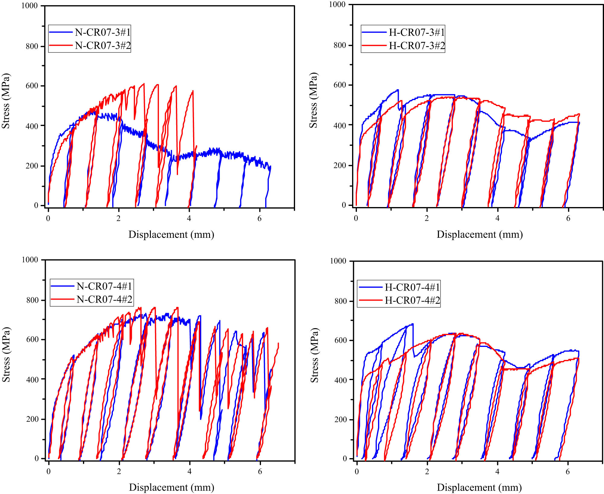
Pullout response of crimped fiber with 0.7 mm diameter.


Pullout response of crimped fiber with 1.0 mm diameter.
The displacement recovery ratio (DRR) and the fiber’s ED during cyclic pullout tests are defined in Figure 6, and their values are summarized in Table 3. Considering the loading process that started from reloading point “A” to unloading “B” and then ended at point “C” (Figure 6), the displacement due to loading from points “A” to “B” was called cycle loading displacement (x), and the displacement due to unloading from points “B” to “C” was called cycle unloading displacement (r). The DRR was defined as the ratio between r and x. The ED was defined as the loop area, which was the area with the red hatch in Figure 6.

Pullout response of crimped fiber with 1.0 mm diameter.
Cyclic pullout parameters of crimped fibers
| Test series | Samples | Maximum pullout stress (MPa) | Displacement (mm) | DRR (%) | Dissipation (N·mm) | Average max pullout stress (MPa) | Average DRR (%) | Average dissipation (N·mm) |
|---|---|---|---|---|---|---|---|---|
| N-PA07 | #1 | 1,100 | 0.7 | 67.6 | 10.7 | 1,100 | 64.5 | 9.9 |
| 1.4 | 65.3 | 28.2 | 62.7 | 25.9 | ||||
| 2.1 | 63.7 | 40.3 | 61.2 | 34.9 | ||||
| 2.8 | 62.0 | 46.2 | 60.3 | 39.7 | ||||
| 3.5 | 62.2 | 46.6 | 60.3 | 44.4 | ||||
| #2 | 1,100 | 0.7 | 61.4 | 9.0 | 61.8 | |||
| 1.41 | 60.2 | 23.7 | ||||||
| 2.11 | 58.7 | 29.4 | ||||||
| 2.81 | 58.6 | 33.2 | ||||||
| 3.5 | 58.3 | 42.1 | ||||||
| N-CR07-1 | #1 | 395 | 0.7 | 31.4 | 3.4 | 356 | 27.9 | 2.6 |
| 1.41 | 30.1 | 5.1 | 24.7 | 3.5 | ||||
| 2.11 | 24.5 | 3.3 | 19.1 | 2.0 | ||||
| 2.8 | 23.7 | 2.5 | 18.0 | 1.3 | ||||
| 3.5 | 16.3 | 1.0 | 12.5 | 0.5 | ||||
| #2 | 317 | 0.7 | 24.3 | 1.9 | 20.4 | |||
| 1.41 | 19.3 | 1.9 | ||||||
| 2.11 | 13.8 | 0.8 | ||||||
| 2.8 | 12.3 | 0.1 | ||||||
| 3.5 | 8.8 | 0.0 | ||||||
| N-CR07-2 | #1 | 480 | 0.7 | 38.6 | 3.1 | 438 | 34.3 | 3.0 |
| 1.41 | 36.3 | 8.0 | 32.3 | 6.1 | ||||
| 2.11 | 33.0 | 8.3 | 29.6 | 6.4 | ||||
| 2.8 | 30.1 | 5.8 | 24.8 | 4.1 | ||||
| 3.5 | 18.8 | 1.9 | 16.1 | 1.4 | ||||
| #2 | 396 | 0.7 | 30.0 | 2.9 | 27.4 | |||
| 1.41 | 28.3 | 4.3 | ||||||
| 2.11 | 26.2 | 4.5 | ||||||
| 2.8 | 19.6 | 2.4 | ||||||
| 3.5 | 13.5 | 0.9 | ||||||
| N-CR07-3 | #1 | 471 | 0.7 | 37.1 | 5.6 | 540 | 39.3 | 5.0 |
| 1.4 | 35.4 | 9.7 | 36.5 | 10.1 | ||||
| 2.11 | 27.6 | 6.6 | 32.3 | 10.6 | ||||
| 2.81 | 26.3 | 4.3 | 28.2 | 7.4 | ||||
| 3.5 | 17.9 | 1.9 | 23.3 | 5.4 | ||||
| #2 | 609 | 0.7 | 41.4 | 4.5 | 31.9 | |||
| 1.41 | 37.6 | 10.5 | ||||||
| 2.11 | 37.0 | 14.5 | ||||||
| 2.81 | 30.1 | 10.5 | ||||||
| 3.5 | 28.7 | 9.0 | ||||||
| N-CR07-4 | #1 | 718 | 0.7 | 52.9 | 13.2 | 737.5 | 55.7 | 13.3 |
| 1.41 | 51.1 | 25.0 | 54.4 | 24.4 | ||||
| 2.11 | 52.8 | 34.3 | 55.3 | 36.3 | ||||
| 2.8 | 53.0 | 37.5 | 54.8 | 36.4 | ||||
| 3.5 | 51.1 | 35.0 | 53.1 | 33.1 | ||||
| #2 | 757 | 0.7 | 58.6 | 13.3 | 54.7 | |||
| 1.4 | 57.6 | 23.9 | ||||||
| 2.11 | 57.8 | 38.4 | ||||||
| 2.81 | 56.7 | 35.3 | ||||||
| 3.5 | 55.1 | 31.2 | ||||||
| H-PA07 | #1 | 1,100 | 0.7 | 70.0 | 18.0 | 1,100 | 66.4 | 16.5 |
| 1.41 | 75.8 | 45.4 | 72.3 | 36.2 | ||||
| 2.11 | 68.9 | 58.2 | 64.5 | 49.6 | ||||
| 2.8 | 65.0 | 59.2 | 61.4 | 50.2 | ||||
| 3.51 | 63.3 | 57.4 | 60.3 | 49.3 | ||||
| #2 | 1,100 | 0.7 | 62.9 | 15.0 | 65.0 | |||
| 1.41 | 68.7 | 27.0 | ||||||
| 2.1 | 60.1 | 41.0 | ||||||
| 2.8 | 57.9 | 41.3 | ||||||
| 3.51 | 57.3 | 41.2 | ||||||
| H-CR07-1 | #1 | 463 | 0.7 | 48.6 | 3.9 | 480.5 | 47.1 | 6.2 |
| 1.4 | 33.8 | 8.8 | 37.8 | 11.1 | ||||
| 2.11 | 32.0 | 7.4 | 36.4 | 10.5 | ||||
| 2.81 | 26.2 | 3.7 | 34.0 | 8.4 | ||||
| 3.5 | 17.7 | 1.6 | 27.5 | 5.9 | ||||
| #2 | 498 | 0.7 | 45.7 | 8.4 | 36.5 | |||
| 1.41 | 41.7 | 13.3 | ||||||
| 2.11 | 40.7 | 13.7 | ||||||
| 2.8 | 41.7 | 13.2 | ||||||
| 3.5 | 37.3 | 10.3 | ||||||
| H-CR07-2 | #1 | 680 | 0.71 | 46.5 | 9.0 | 663.5 | 45.5 | 7.7 |
| 1.41 | 44.7 | 16.2 | 43.8 | 18.2 | ||||
| 2.1 | 43.0 | 9.9 | 43.0 | 17.2 | ||||
| 2.8 | 36.1 | 7.8 | 35.9 | 13.1 | ||||
| 3.5 | 33.0 | 5.6 | 32.1 | 7.2 | ||||
| #2 | 647 | 0.7 | 44.4 | 6.4 | 40.1 | |||
| 1.41 | 43.0 | 20.2 | ||||||
| 2.11 | 43.0 | 24.6 | ||||||
| 2.8 | 35.6 | 18.3 | ||||||
| 3.5 | 31.2 | 8.8 | ||||||
| H-CR07-3 | #1 | 551 | 0.71 | 56.3 | 13.4 | 546 | 54.9 | 12.6 |
| 1.41 | 46.4 | 20.3 | 46.3 | 19.4 | ||||
| 2.1 | 41.7 | 15.6 | 41.7 | 15.4 | ||||
| 2.8 | 41.7 | 14.7 | 42.7 | 14.5 | ||||
| 3.5 | 40.0 | 12.5 | 40.9 | 13.0 | ||||
| #2 | 541 | 0.71 | 53.5 | 11.8 | 45.3 | |||
| 1.41 | 46.3 | 18.6 | ||||||
| 2.11 | 41.7 | 15.3 | ||||||
| 2.8 | 43.7 | 14.3 | ||||||
| 3.5 | 41.8 | 13.4 | ||||||
| H-CR07-4 | #1 | 673 | 0.7 | 78.6 | 22.8 | 650.5 | 72.1 | 17.5 |
| 1.4 | 75.2 | 51.9 | 66.6 | 38.6 | ||||
| 2.11 | 60.9 | 39.3 | 57.0 | 30.8 | ||||
| 2.81 | 54.3 | 29.6 | 53.6 | 24.3 | ||||
| 3.5 | 52.0 | 26.7 | 50.1 | 21.6 | ||||
| #2 | 628 | 0.7 | 65.7 | 12.1 | 59.9 | |||
| 1.41 | 58.0 | 25.4 | ||||||
| 2.11 | 53.0 | 22.3 | ||||||
| 2.81 | 52.9 | 18.9 | ||||||
| 3.5 | 48.3 | 16.6 | ||||||
| N-PA10 | #1 | 1,100 | 0.52 | 58.3 | 4.5 | 1,100 | 55.6 | 3.4 |
| 1.03 | 57.6 | 15.9 | 51.8 | 10.8 | ||||
| 1.82 | 55.4 | 30.6 | 49.9 | 22.8 | ||||
| 2.51 | 54.0 | 55.6 | 48.9 | 38.1 | ||||
| 2.92 | 52.6 | 66.1 | 46.9 | 50.6 | ||||
| #2 | 1,100 | 0.51 | 52.9 | 2.2 | 50.6 | |||
| 1.00 | 46.1 | 5.7 | ||||||
| 1.82 | 44.4 | 15.0 | ||||||
| 2.50 | 43.8 | 20.6 | ||||||
| 2.92 | 41.1 | 35.0 | ||||||
| N-CR10-1 | #1 | 427 | 0.52 | 45.4 | 2.4 | 383.5 | 40.4 | 2.0 |
| 1.00 | 41.5 | 8.8 | 36.2 | 6.1 | ||||
| 1.83 | 25.5 | 7.8 | 21.5 | 4.6 | ||||
| 2.51 | 13.5 | 1.5 | 8.5 | 0.8 | ||||
| 2.92 | 5.6 | 0.0 | 26.6 | |||||
| #2 | 340 | 0.52 | 35.4 | 1.7 | ||||
| 1.00 | 30.8 | 3.4 | ||||||
| 1.83 | 17.5 | 1.4 | ||||||
| 2.51 | 3.5 | 0.0 | ||||||
| N-CR10-2 | #1 | 491 | 0.52 | 51.7 | 4.7 | 528 | 50.4 | 5.9 |
| 1.00 | 50.0 | 15.9 | 48.6 | 16.3 | ||||
| 1.83 | 29.9 | 13.7 | 32.9 | 18.6 | ||||
| 2.51 | 23.3 | 5.3 | 27.1 | 8.7 | ||||
| 2.92 | 20.0 | 0.5 | 21.3 | 1.5 | ||||
| #2 | 565 | 0.52 | 49.1 | 7.1 | 36.1 | |||
| 1.00 | 47.2 | 16.8 | ||||||
| 1.83 | 35.9 | 23.5 | ||||||
| 2.51 | 30.9 | 12.1 | ||||||
| 2.92 | 22.7 | 2.6 | ||||||
| N-CR10-3 | #1 | 662 | 0.52 | 67.3 | 12.9 | 772.5 | 67.5 | 10.8 |
| 1.00 | 66.3 | 37.5 | 65.7 | 37.2 | ||||
| 1.82 | 59.9 | 41.2 | 61.4 | 59.8 | ||||
| 2.51 | 57.6 | 30.1 | 59.0 | 68.0 | ||||
| 2.92 | 55.3 | 22.2 | 55.7 | 64.4 | ||||
| #2 | 882 | 0.52 | 67.7 | 8.7 | 61.9 | |||
| 1.00 | 65.1 | 36.9 | ||||||
| 1.82 | 63.0 | 78.4 | ||||||
| 2.51 | 60.5 | 105.9 | ||||||
| 2.92 | 56.2 | 106.5 | ||||||
| N-CR10-4 | #1 | 979 | 0.52 | 73.1 | 10.3 | 905.5 | 66.3 | 9.3 |
| 1.03 | 72.0 | 45.5 | 65.3 | 40.4 | ||||
| 1.82 | 66.7 | 101.8 | 62.2 | 92.7 | ||||
| 2.51 | 65.7 | 127.9 | 60.5 | 106.2 | ||||
| 2.92 | 62.8 | 115.9 | 58.9 | 89.6 | ||||
| #2 | 832 | 0.52 | 59.6 | 8.3 | 62.7 | |||
| 1.00 | 58.6 | 35.4 | ||||||
| 1.82 | 57.7 | 83.6 | ||||||
| 2.51 | 55.4 | 84.6 | ||||||
| 2.92 | 55.0 | 63.4 | ||||||
| H-PA10 | #1 | 1,100 | 0.51 | 71.5 | 6.5 | 1,100 | 69.1 | 5.8 |
| 1.03 | 72.7 | 23.6 | 68.6 | 24.3 | ||||
| 1.82 | 73.0 | 75.2 | 68.3 | 80.5 | ||||
| 2.51 | 74.8 | 108.2 | 67.7 | 113.7 | ||||
| 2.92 | 79.8 | 115.3 | 66.8 | 119.9 | ||||
| #2 | 1,100 | 0.52 | 66.7 | 5.2 | 68.1 | |||
| 1.00 | 70.6 | 25.0 | ||||||
| 1.82 | 73.6 | 85.7 | ||||||
| 2.51 | 74.6 | 119.1 | ||||||
| 2.92 | 79.8 | 124.4 | ||||||
| H-CR10-1 | #1 | 468 | 0.31 | 41.9 | 1.0 | 415 | 37.1 | 1.3 |
| 1.51 | 22.6 | 9.3 | 19.0 | 14.7 | ||||
| 3.02 | 3.3 | 0.1 | 3.7 | 0.1 | ||||
| #2 | 362 | 0.31 | 32.3 | 1.7 | 19.9 | |||
| 1.51 | 15.4 | 20.1 | ||||||
| 3.02 | 4.1 | 0.1 | ||||||
| H-CR10-2 | #1 | 498 | 0.31 | 54.8 | 1.7 | 562 | 59.7 | 1.5 |
| 1.51 | 27.7 | 20.1 | 35.7 | 35.2 | ||||
| 3.02 | 3.7 | 0.1 | 14.8 | 13.9 | ||||
| #2 | 626 | 0.31 | 64.5 | 1.3 | 36.7 | |||
| 1.51 | 43.6 | 50.3 | ||||||
| 3.02 | 25.9 | 27.7 | ||||||
| H-CR10-3 | #1 | 787 | 0.52 | 76.1 | 8.3 | 780.5 | 74.6 | 6.6 |
| 1.00 | 75.6 | 38.0 | 72.6 | 37.1 | ||||
| 1.83 | 64.9 | 79.0 | 64.0 | 78.4 | ||||
| 2.51 | 62.8 | 88.9 | 61.8 | 88.6 | ||||
| 2.92 | 60.7 | 66.4 | 60.3 | 70.9 | ||||
| #2 | 774 | 0.52 | 73.1 | 4.8 | 66.6 | |||
| 1.03 | 69.7 | 36.2 | ||||||
| 1.82 | 63.1 | 77.8 | ||||||
| 2.51 | 60.8 | 88.3 | ||||||
| 2.92 | 59.9 | 75.3 | ||||||
| H-CR10-4 | #1 | 881 | 0.52 | 77.1 | 7.0 | 849.5 | 76.1 | 9.5 |
| 1.00 | 76.7 | 39.3 | 75.2 | 41.7 | ||||
| 1.82 | 73.4 | 115.2 | 68.0 | 103.3 | ||||
| 2.51 | 72.0 | 147.1 | 67.0 | 125.2 | ||||
| 2.92 | 70.9 | 141.6 | 65.5 | 116.2 | ||||
| #2 | 818 | 0.52 | 75.1 | 12.0 | 70.3 | |||
| 1.00 | 73.6 | 44.1 | ||||||
| 1.82 | 62.6 | 91.5 | ||||||
| 2.51 | 62.1 | 103.4 | ||||||
| 2.92 | 60.1 | 90.9 |
In a previous study, the SE SMA fibers with L- and N-shapes did not show displacement recovery as well as ED because the anchoring bond of these fibers was too weak [24]. Only the SE SMA paddled fiber with a high bond resistance presented flag-shaped behavior at a large displacement with displacement recovery and ED capacities. In this study, the cold-drawn paddled and crimped fibers all showed hysteretic behavior from the initial cycle loading. This was caused from the tensile behavior and the high anchoring resistance of the cold-drawn fiber. As previously mentioned, the cold-drawn fiber did not show perfect elastic and plastic behavior. Thus, the fiber contained residual displacement after each cycle loading, even at a small displacement loading. Moreover, the high anchoring bond guaranteed that the fiber was deformed during loading and then could recover the displacement when unloading.
3.1 Maximum pullout stress
The comparison of the maximum pullout stress of crimped fibers in heating and non-heating cases is presented in Figure 7. For the N-CR07 fibers, the maximum pullout stress increased from CR1 to CR4 fibers due to the increase of the wave depth, which ranged from 0.055 to 0.124 mm. Due to the SME under heating treatment, the fiber bulged in diameter and reduced the wave depth, as shown in Table 1. The increasing diameter was significant for shallow crimped fibers, while the decreasing wave depth was dramatic for deep crimped fibers. The diameter increased from 0.006 to 0.003 mm, and the wave depth reductions were from −0.021 to −0.032 mm for the CR07-1 to CR07-4 fiber, respectively. Thus, the H-CR07-1 and H-CR07-2 fibers introduced a significantly higher maximum pullout stress than the non-heated fibers, whereas the H-CR07-3 fiber provided a little higher maximum pullout stress compared to the N-CR07-3 fiber. In addition, the H-CR07-4 fiber showed a smaller maximum pullout stress than the N-CR07-4 fiber.

Maximum pullout stress of crimped fibers with and without heating.
The same phenomenon occurred for the CR10 fibers. Deep crimped fibers had a higher maximum pullout stress compared to shallow crimped fibers in the non-heating case. In the heating case, the CR10-1, CR10-2, and CR10-3 fibers increased the maximum pullout stress because of the significantly increasing diameter and the slightly reducing wave depth, while the CR10-4 fibers decreased the maximum pullout stress.
The different wave depth fibers produced different changes in the diameter and wave depth due to heating. Therefore, the wave depth of crimped fibers is an important parameter that must be considered to introduce reasonable pullout resistances to the crimped fiber in both heating and non-heating cases. These pullout resistances contribute to the tensile behavior and crack-closing of the reinforced concrete/mortar. A wave depth of about 0.1 mm for the CR07-3 and CR10-3 fibers seems to be optimal wave depth for the constant maximum pullout stress due to heating. The maximum pullout stress differences due to the heating of the CR07-3 and CR10-3 fibers are only 6 and 8 MPa, respectively.
Moreover, the variation of the maximum pullout stress due to heating is more serious for the CR07 fibers. The maximum pullout stress increased by about 124.5, 225.5, and 6 MPa for the CR07-1 to CR07-3 fibers and decreased by about 87 MPa for the CR07-4 fiber. These values were only 31.5, 34, and 8 MPa increments for the CR10-1 to CR10-3 fibers and 56 MPa decrement for the CR10-4 fiber. This behavior can be explained by the thin shape and lower flexural stiffness of the CR07 fibers. The small diameter of the CR07 fiber guaranteed that all parts of the fibers completed phase transformation. Moreover, the flexural stiffness of the CR07 fiber is only a quarter of the CR10 fiber when considering the same wave depth. Previous monotonic pullout tests also verified this behavior [12].
3.2 Displacement recovery ratio (DRR)
The recovery displacement mechanism of the fiber is explained in Figure 8. For simplicity, the fiber with end-anchorage is illustrated. However, this mechanism is also true for other anchoring fibers, such as crimped fibers. In reloading, the fiber slipped and deformed into longitudinal fiber (x). The adhesive bond between the fiber and surrounding mortar matrix was fractured when the slip occurred. Then, the anchoring bond and frictional bond contributed to the pullout resistance of the fiber. The adhesive bond was small and just appeared in the initial slip. Thus, it was neglected in the cyclic pullout behavior of the fiber. In unloading, the fiber recovered its deformation (r), which depended on the fiber’s tensile properties, and caused a recovery force in the fiber. Noting that, the anchoring bond was important for recovery deformation. The anchorage played as a fixed point, while other parts of fiber recovered the deformation at the anchoring point.

Recovery deformation mechanism of the fiber at each cycle loading.
Figure 9 presents the DRRs of the paddled and crimped fibers in heating and non-heating cases, which are also summarized in Table 3. Generally, the DRR of the non-heated 0.7 mm diameter fibers reduced after each cycle loading. The reductions of the DRRs after the first-five cycles until displacement of 3.5 mm were 6.6% for the N-PA07 fiber and 55.5, 52.9, 40.7, and 4.7% for the N-CR07-1 to N-CR07-4 fibers. This phenomenon happened because of reduced friction due to the damage of the mortar duct after each unloading–reloading cycle. The N-PA07 and N-CR07-4 fibers had high anchoring bonds due to their paddled end or high wave depth; their anchoring bond was significantly higher than their frictional bond. Thus, the reduction of the DRR of these fibers was significant. In contrast, the N-CR07-1 to N-CR07-3 fibers with a shallow wave depth depended more on the frictional bond and thus were influenced more by the damage of the mortar duct. The reductions of the DRR for these shallow crimped fibers were relatively large, with about 40.7–55.5%. For the heating case, the fiber diameters increased due to the SME, whereas the wave depth of the crimped fibers became smaller due to the stretching effect. The bugling in diameter of the H-CR07-1 to H-CR07-3 fibers seemed more significant than the stretching. The increased frictional resistance caused the DRR reduction; the values were 42.55, 28.29, and 25.45%, respectively. For the high anchoring bond fibers of CR07-4 and PA07 fibers, the frictional resistance was small compared to the anchoring bond. Thus, the DRR reduction was almost unchanged. These values were 9.5 and 9.09%, respectively.
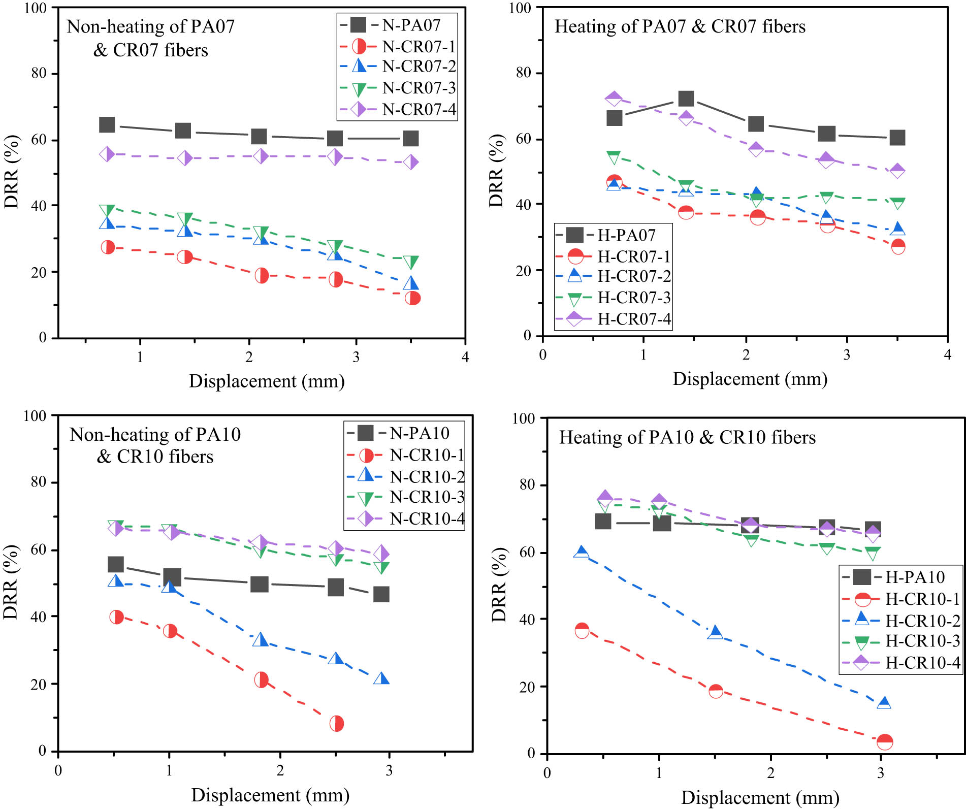
DRRs of paddled and crimped fibers with and without heating.
The average DRRs after the first-five cycles of the fibers were 61.8, 20.4, 27.4, 31.9, and 54.7% for N-PA07 and N-CR07-1 to N-CR07-4 fibers, respectively. The fibers with a higher anchoring bond produced a higher average DRR. In the heating case, the average DRRs of the heated fibers were 65.0, 36.5, 40.1, 45.3, and 59.9%, respectively. Thus, the average DRR of each fiber after the first-five cycles increased due to heating. In the previous monotonic pullout test [12], the authors found that the cold-drawn SMA fiber shrunk at temperatures higher than the finished austenite temperature (A f) and exhibited prestressing in the fiber.
For the non-heating case, the displacement recovery behavior of 1.0 mm diameter fibers was similar to that of the 0.7 mm diameter fibers. A deeper crimped fiber showed a smaller DRR reduction than a shallow fiber. The DRR reductions until 3 mm displacement of the N-CR10-3 and CR10-4 fibers were 17.91 and 9.09%, respectively. In comparison, those of the N-CR10-1 and CR10-2 fibers were significant with 78.75 and 58.0%, respectively. The N-PA10 fibers also presented a relatively small DRR reduction of only 16.36% because of the high anchoring bond provided by the paddled-end anchorage. The average DRRs decreased from 62.7% for N-CR10-4 fibers to 26.6% for N-CR10-1 fibers. These average DRRs of N-CR10 fibers were not much higher than those of N-CR07 fibers, while the cross-sectional area of N-CR10 fibers was double that of the N-CR07 fibers.
For the heating case, the DRR reductions after cycle loading were 90.0, 74.87, 19.57, and 13.82% for the H-CR10-1 to H-CR10-4 fibers. The DRR reductions of the H-CR10 fibers were significant due to the heating. This behavior was different from that of H-CR07 fibers. The reason was the stretching effect that exceeded the bugling effect for H-CR10 fibers. The CR10 fibers had a larger cross-sectional area than the H-CR07 fibers; thus, it may be hard to activate full phase transformation in all parts in the cross-section of the H-CR10 fiber. The prestressing in the H-CR10 fibers because of the SME due to heating also changed the DRRs. In turn, the average DRRs of the H-CR10-1 to H-CR10-4 fibers were 19.9, 36.7, 66.6, and 70.3%, respectively. The H-CR10-4 fibers increased average DRR due to the heating, while the other shallower H-CR10 fibers decreased the average DRRs. Noting that, the CR07-1 to CR07-3 fibers and the CR10-1 to CR10-3 fibers had almost the same shallow wave depth of 0.03–0.064 mm. However, they showed the opposite trend of average DRRs due to the heating. The CR07-4 and CR10-4 fibers had a relatively large wave depth of 0.092 and 0.112 mm presented in the same increasing trend of average DRRs due to the heating. The pullout resistance of fiber seems important for DRR behavior. The high anchoring bond guarantees the prestressing because of SME. However, if the anchoring bond is too weak, the prestressing could show its effect.
The H-PA10 fiber also introduced a relatively small DRR reduction of 3.3% after the first-five cycle loadings. This behavior was similar to that of the H-PA07 fiber and could be explained by the significantly high anchoring bond compared to the frictional bond of the PA fiber. Generally, the average DRRs of all heated 1.0 mm diameter fibers increased because of the prestressing in fiber due to the heating. The maximum average DRR of the H-CR10 fibers was 70.3% for the H-CR10-4 fibers, which was a little higher than the maximum average DRR of 59.9% for the H-CR07 fibers (CR07-4 fiber). Thus, the H-CR07 fibers were more effective than the H-CR10 fibers in recovery displacement behavior. Moreover, high wave depth crimped fibers that produce high anchoring resistance should be used to introduce a relatively high DRR value.
3.3 Energy dissipation (ED)
The ED after each cycle until 3.5 mm displacement of the fibers are presented in Figure 10; these values are summarized in Table 3. Overall, the shape of the ED–displacement curve looked like that of the pullout stress response of the fiber. There was an increased curve for the PA fibers and a parabolic curve for the CR fibers. This phenomenon was due to the area of each loop (i.e., ED) being influenced by the pullout stress at an unloading point.

EDs of paddled and crimped fibers with and without heating.
The ED depended on the pullout resistance of the fiber. This was relatively high for the PA07 and CR07-4 fibers and was small for the low anchoring bond fibers of the CR07-1 to CR07-3 fibers (Figure 10a and b). The same phenomenon occurred for the 1.0 mm diameter fibers. The ED curve of the CR10-4 fiber was above that of the CR10-3 fiber, the next one was the ED curve of the CR10-2 fiber, and the lowest one was of the CR10-1 fiber, as shown in Figure 10c and d. It was easy to understand this because the ED depended on the pullout stress and the DRR value. The high anchoring bond fibers, including the PA fiber and the crimped fiber with high wave depth, introduced a relatively high pullout stress, as presented and discussed in Section 3.1. Moreover, the DRR was also relatively high for fibers with a high anchoring bond, as demonstrated in Section 3.2.
The prestressing in the fiber, which is due to the SME with heating generally increased the ED. The maximum EDs were relatively high with 44.4 and 36.4 N·mm for the N-PA07 and N-CR07-4 fibers, and small for the N-CR07-1 to N-CR07-3 fibers with only 3.5, 6.4, and 10.6 N·mm, respectively. Due to heat treatment, the maximum EDs increased to 50.2, 11.1, 18.2, 19.4, and 38.6 N·mm for H-PA07 and H-CR07-1 to H-CR07-4 fibers. The 1.0 mm diameter fibers showed the same ED behavior compared to the 0.7 mm diameter fiber. The maximum EDs of N-CR10-1 to N-CR10-4 fibers were 6.1, 18.6, 68.0, and 106.2 N·mm, respectively. In comparison, the values of the H-CR10-1 to H-CR10-4 fibers were 14.7, 35.2, 88.6, and 125.2 N·mm, respectively. The maximum ED of the PA10 fiber also increased from 50.6 to 119.9 N·mm.
Concerning the diameter effect, the 1.0 mm diameter fibers introduced higher maximum EDs than the 0.7 mm diameter fibers in both non-heating and heating cases. For example, regarding the N-CR07-1 and N-CR10-1 fibers with nearly the same wave depth of 0.055 mm, their maximum EDs were 3.5 and 6.1 N·mm, respectively. Meanwhile, the H-CR07-2 and H-CR10-2 fibers with nearly the same wave depth of 0.037 mm had maximum EDs of 187.2 and 35.2 N·mm, respectively. However, it should be noted that the cross-sectional area of the 0.7 mm diameter fiber was just half when compared to the 1.0 mm diameter fiber. Thus, with the same volume fiber, the number of 0.7 mm diameter fiber mixed in a mortar matrix was double that of the 1.0 mm diameter fiber. Thus, the mono fiber of 1.0 mm diameter showed higher maximum EDs than that of the 0.7 mm diameter fiber. However, the reinforced mortar that contained 1.0 mm diameter fiber might not have higher maximum EDs than the 0.7 mm diameter fiber-reinforced mortar.
4 Discussions
The bent steel fibers, namely, end-hooked and crimped, are assumed to be yielded at the bent part during the pulling out process [34]. Plastic deformation was developed at the bent part while passing through the duct, and, thus, a large ED occurred. However, the crimped SMA fibers were generally manufactured to not be yielded during the pulling out process, but also the yielding inhibited the inducement of the recovery stress in the SMA fiber. Therefore, the stress distribution of such steel fibers at the bent part was assumed to be rectangular with the yield stress for both tensile and compressive parts (Figure 11a). However, the stress distribution of the crimped SMA fiber should be linear from the maximum tensile stress to the corresponding compressive stress as shown in Figure 11b. For the bent steel fiber, the plastic energy was dissipated, but the strain energy of the crimped SMA fiber was stored. As a result, the stored energy was released during the unloading process. It was expected that the stored energy would help recover the loaded displacement because the stored energy helped recover the deformation at the elastic bent part. Consequently, it can be argued that more stored energy can induce more displacement recovery.
![Figure 11
Stress and strain distribution of bent fibers subjected to tension: (a) plastic bent fiber [34] and (b) elastic bent fiber.](/document/doi/10.1515/rams-2022-0285/asset/graphic/j_rams-2022-0285_fig_011.jpg)
Stress and strain distribution of bent fibers subjected to tension: (a) plastic bent fiber [34] and (b) elastic bent fiber.
Ho et al. [27] estimated the stress distribution of the crimped SMA fiber during pulling out using a finite element model. They showed that the stress distribution of the convex part (the A-A cross-section in Figure 12) of the SMA fiber was reversed at the concave part of the fiber (i.e., the B-B cross section).
![Figure 12
Stress distributions of the crimped SMA fiber at different locations [27].](/document/doi/10.1515/rams-2022-0285/asset/graphic/j_rams-2022-0285_fig_012.jpg)
Stress distributions of the crimped SMA fiber at different locations [27].
This indicates that the stresses at the top and bottom of the fiber could be maximized when the convex part of the fiber was placed at the concave shape of the duct. Thus, the stored energy would be maximized, resulting in maximum displacement recovery during the unloading. The N-CR10-1 and N-CR10-2 cases in Figure 13a showed the maximum displacement recovery with a slip of around half of the wavelength, which was 1.65 mm in this study. The two SMA fibers had a relatively small wave depth, and, thus, the developed stress was below the yield stress. However, the other two fibers of the N-CR10-3 and N-CR10-4 cases had a relatively large wave depth, which resulted in a large stress in the fiber and elongated the period of pullout response as shown in Figure 5g and i. Thus, the conjecture was not valid, and the maximum displacement recovery occurred at the deviated location from the half wavelength. For the heated crimped SMA fibers, the displacement recovery showed the same trend as the non-heated cases. For the CR07 SMA fibers in Figure 13c and d, the maximum displacement recovery occurred around of the 1.5 mm slip, and, thus, it can be said that the above conjecture was valid for the CR07 SMA fiber. However, the displacement recovery trend did not match well with the conjecture. It seemed that the relatively low flexural rigidity of the CR07 SMA fiber compared to that of the CR10 fiber induced such displacement recovery.

Displacement recovery of crimped SMA fibers (a) N-CR10, (b) H-CR10, (c) N-CR07, and (d) H-CR07.
The notable thing was that the displacement recovery became larger with a larger wave depth of the fiber, regardless of the fiber’s diameter and heating. Thus, a crimped SMA fiber with a larger wave depth could save more stored energy during pulling out. Finally, it should be noted that the trend of the displacement recovery was almost the same as that of the dissipated energy in Figure 10. The ED was mainly from the friction during the displacement recovery. Thus, it can be said that more displacement recovery induces more ED.
The DRR was used to estimate the displacement recovery capacity of the SE SMA fibers in a previous study [35]. If the displacement recovery was a function of applied incremental displacement, which is x in Figure 6, the DRR could be used and had meaningful information. However, in the tests of this study, the recovery displacement might not have been related to the applied incremental displacement, but it depended on the unloading position. Thus, if the applied incremental displacement became large, the DRR at a specific unloading point should decrease because the displacement recovery at a specific point was the same, regardless of the applied incremental displacement. Thus, in this study, the recovered displacement seemed to be more essential to understand the displacement recovery behavior of the crimped SMA fiber.
5 Conclusions
This study investigated the cyclic pullout behavior of cold-drawn crimped fibers, including the maximum pullout stress, the displacement recovery, and the ED. The cold-drawn paddled fibers were also examined to compare the cyclic pullout behavior of crimped fibers with multiple anchoring bonds and that of paddled fibers with a high end-anchoring bond. For this purpose, the fibers with two diameters of 0.7 and 1.0 mm were prepared, prestrain was introduced by cold drawing work, and paddled and crimped shapes were fabricated. The pullout specimens were tested in heating and non-heating cases to investigate the effect of recovery stress in the fiber due to heating on the cyclic pullout behavior. Based on the experimental results, the following conclusions can be drawn:
The maximum pullout stress of crimped SMA fibers depended on the fiber’s wave depth, and the crimped SMA fibers with a larger wave depth induced a higher pullout resistance.
The fiber’s diameter increased due to heating, while the fiber’s wave depth decreased. The diameter’s increment was significant for the shallow crimped fibers to increase pullout resistance, while the wave depth reduction was critical for the deep crimped fibers to decrease the pullout resistance. Thus, the heating increased the maximum pullout stress of the shallow crimped fibers but decreased that of the deep crimped fibers.
The DRRs of the paddled and crimped fibers were reduced after cyclic loadings due to the reduction of friction caused by the damaged mortar duct. The DRR reductions were significant for low anchoring bond fibers and were neglected for the high anchoring bond fibers. Moreover, the higher anchoring bond fiber introduced a higher average DRR.
The average DRR of the fibers increased due to the heating. The prestressing in the fibers because of the SME due to heating shrunk the fiber and produced more displacement recovery. However, the prestressing only presented its effect for the fiber with a high anchoring bond.
The fibers with a higher anchoring bond generated a higher ED. For the heating case, the prestressing in the fiber contributed more to the increased ED. The 1.0 mm diameter fiber produced a higher ED than the 0.7 mm diameter for both non-heating and heating cases.
The pattern of the displacement recovery was similar to the shape of the fiber’s wave, and the maximum displacement recovery occurred with the slip of half the wavelength. Moreover, the trend of the displacement recovery was almost the same as ED. This means that a larger displacement recovery can induce a larger ED.
-
Funding information: This work was supported by a National Research Foundation of Korea (NRF) grant funded by the Korean government (MEST) (Project No. NRF 2020R1A4A-1018826).
-
Author contributions: Conceptualization, methodology, E.C.; formal analysis, E.C and J.H.L.; investigation and data curation, J.C. and J.H.L; writing – original draft preparation, E.C.; writing – review and editing, J.C. and J.H.L.; visualization, J.C.; supervision, E.C.; project administration, E.C.; and funding acquisition, E.C. All authors have accepted responsibility for the entire content of this manuscript and approved its submission.
-
Conflict of interest: The authors state no conflict of interest.
References
[1] Janke, L., C. Czaderski, M. Motavalli, and J. Ruth. Applications of shape memory alloys in civil engineering structures – overview, limits and new ideas. Materials and Structures, Vol. 38, No. 5, 2005, pp. 578–592.10.1007/BF02479550Search in Google Scholar
[2] Ostadrahimi, A. and F. Taheri-Behrooz. Analytical solution for twinning deformation effect of pre-strained shape memory effect beam-columns. Journal of Intelligent Material Systems and Structures, Vol. 30, No. 14, 2019, pp. 2147–2165.10.1177/1045389X19862380Search in Google Scholar
[3] Ostadrahimi, A., J. Arghavani, and S. Poorasadion. An analytical study on the bending of prismatic SMA beams. Smart Materials and Structures, Vol. 24, No. 12, 2015, id. 125035.10.1088/0964-1726/24/12/125035Search in Google Scholar
[4] Choi, E., H. V. Ho, and J. Seo. Dynamic behaviors of mortar reinforced with NiTi SMA fibers under impact compressive loading. Materials, Vol. 14, No. 17, 2021, id. 4933.10.3390/ma14174933Search in Google Scholar PubMed PubMed Central
[5] Ostadrahimi, A., F. Taheri-Behrooz, and E. Choi. Effect of tension–compression asymmetry response on the bending of prismatic martensitic SMA beams: analytical and experimental study. Materials, Vol. 14, No. 18, 2021, id. 5415.10.3390/ma14185415Search in Google Scholar PubMed PubMed Central
[6] Choi, E., A. Ostadrahimi, W. J. Kim, and J. Seo. Prestressing effect of embedded Fe-based SMA wire on the flexural behavior of mortar beams. Engineering Structures, Vol. 227, 2021, id. 111472.10.1016/j.engstruct.2020.111472Search in Google Scholar
[7] Wierschem, N. and B. Andrawes. Superelastic SMA–FRP composite reinforcement for concrete structures. Smart Materials and Structures, Vol. 19, No. 2, 2010, id. 025011.10.1088/0964-1726/19/2/025011Search in Google Scholar
[8] Liang, D., Y. Zheng, C. Fang, M. C. Yam, and C. Zhang. Shape memory alloy (SMA)-cable-controlled sliding bearings: development, testing, and system behavior. Smart Materials and Structures, Vol. 29, No. 8, 2020, id. 085006.10.1088/1361-665X/ab8f68Search in Google Scholar
[9] Taheri-Behrooz, F., M. J. Mahdavizade, and A. Ostadrahimi. Micromechanics of stress transfer in shape memory alloy reinforced three-phase composites. Journal of Intelligent Material Systems and Structures, Vol. 29, No. 15, 2018, pp. 3151–3164.10.1177/1045389X18783086Search in Google Scholar
[10] Shi, Y., H. Qian, L. Kang, Z. Li, and L. Xia. Cyclic behavior of superelastic SMA cable and its application in an innovative self-centering BRB. Smart Materials and Structures, Vol. 30, No. 9, 2021, id. 095019.10.1088/1361-665X/ac1907Search in Google Scholar
[11] Qiu, C., C. Fang, D. Liang, X. Du, and M. C. Yam. Behavior and application of self-centering dampers equipped with buckling-restrained SMA bars. Smart Materials and Structures, Vol. 29, No. 3, 2020, id. 035009.10.1088/1361-665X/ab6883Search in Google Scholar
[12] Choi, E., H. V. Ho, and J. S. Jeon. Active reinforcing fiber of cementitious materials using crimped NiTi SMA fiber for crack-bridging and pullout resistance. Materials, Vol. 13, No. 17, 2020, id. 3845.10.3390/ma13173845Search in Google Scholar PubMed PubMed Central
[13] Ho, H. V., E. Choi, D. Kim, and J. Kang. Straining behavior of mortar reinforced by cold drawn crimped and dog-bone-shaped fibers under monotonic and cyclic compressions. Materials, Vol. 14, No. 6, 2021, id. 1522.10.3390/ma14061522Search in Google Scholar PubMed PubMed Central
[14] Vahidi, S., J. Arghavani, E. Choi, and A. Ostadrahimi. Mechanical response of single and double-helix SMA wire ropes. Mechanics of Advanced Materials and Structures, 2021. https://doi.org/10.1080/15376494.2021.1955313.10.1080/15376494.2021.1955313Search in Google Scholar
[15] Dong, H., X. Du, and Q. Han. Seismic responses of steel frame structures with self-centering energy dissipation braced on shape memory alloy cables. Advances in Structural Engineering, Vol. 22, No. 9, 2019, pp. 2136–2148.10.1177/1369433219834752Search in Google Scholar
[16] Wang, B. and S. Zhu. Seismic behavior of self-centering reinforced concrete wall enabled by superelastic shape memory alloy bars. Bulletin of Earthquake Engineering, Vol. 16, No. 1, 2018, pp. 479–502.10.1007/s10518-017-0213-8Search in Google Scholar
[17] Shajil, N., S. M. Srinivasan, and M. Santhanam. Self-centering of shape memory alloy fiber reinforced cement mortar members subjected to strong cyclic loading. Materials and Structures, Vol. 46, No. 4, 2013, pp. 651–661.10.1617/s11527-012-9923-1Search in Google Scholar
[18] Dehghani, A. and F. Aslani. Crack recovery and re-centring performance of cementitious composites with pseudoelastic shape memory alloy fibres. Construction and Building Materials, Vol. 298, 2021, id. 123888.10.1016/j.conbuildmat.2021.123888Search in Google Scholar
[19] Wang, Y., F. Aslani, and Y. Liu. The effect of tensile and bond characteristics of NiTi shape memory alloy, steel and polypropylene fibres on FRSCC beams under three-point flexural test. Construction and Building Materials, Vol. 233, 2020, id. 117333.10.1016/j.conbuildmat.2019.117333Search in Google Scholar
[20] Sherif, M. M., E. M. Khakimova, O. E. Ozbulut, D. K. Harris, and H. C. Ozyildirim. Behavior of mortar beams with randomly distributed superelastic shape memory alloy fibers. Journal of Intelligent Material Systems and Structures, Vol. 29, No. 4, 2018, pp. 684–695.10.1177/1045389X17721029Search in Google Scholar
[21] Choi, E., D. Kim, Y. S. Chung, and T. H. Nam. Bond–slip characteristics of SMA reinforcing fibers obtained by pullout tests. Materials Research Bulletin, Vol. 58, 2014, pp. 28–31.10.1016/j.materresbull.2014.04.060Search in Google Scholar
[22] Maji, A. K. and I. Negret. Smart prestressing with shape-memory alloy. Journal of Engineering Mechanics, Vol. 124, No. 10, 1998, pp. 1121–1128.10.1061/(ASCE)0733-9399(1998)124:10(1121)Search in Google Scholar
[23] Li, L., Q. Li, and F. Zhang. Behavior of smart concrete beams with embedded shape memory alloy bundles. Journal of Intelligent Material Systems and Structures, Vol. 18, No. 10, 2007, pp. 1003–1014.10.1177/1045389X06071974Search in Google Scholar
[24] Choi, E., B. Mohammadzadeh, J. H. Hwang, and W. J. Kim. Pullout behavior of superelastic SMA fibers with various end-shapes embedded in cement mortar. Construction and Building Materials, Vol. 167, 2018, pp. 605–616.10.1016/j.conbuildmat.2018.02.070Search in Google Scholar
[25] Kim, D. J., H. A. Kim, Y. S. Chung, and E. Choi. Pullout resistance of deformed shape memory alloy fibers embedded in cement mortar. Journal of Intelligent Material Systems and Structures, Vol. 27, No. 2, 2016, pp. 249–260.10.1177/1045389X14566524Search in Google Scholar
[26] Choi, E., A. Ostadrahimi, and J. H. Lee. Pullout resistance of crimped reinforcing fibers using cold-drawn NiTi SMA wires. Construction and Building Materials, Vol. 265, 2020, id. 120858.10.1016/j.conbuildmat.2020.120858Search in Google Scholar
[27] Ho, H. V., E. Choi, and S. J. Park. Investigating stress distribution of crimped SMA fibers during pullout behavior using experimental testing and a finite element model. Composite Structures, Vol. 272, 2021, id. 114254.10.1016/j.compstruct.2021.114254Search in Google Scholar
[28] Ho, H. V., E. Choi, and J. W. Kang. Analytical bond behavior of cold drawn SMA crimped fibers considering embedded length and fiber wave depth. Reviews on Advanced Materials Science, Vol. 60, No. 1, 2021, pp. 862–883.10.1515/rams-2021-0066Search in Google Scholar
[29] Lin, H. C., S. K. Wu, T. S. Chou, and H. P. Kao. The effects of cold rolling on the martensitic transformation of an equiatomic TiNi alloy. Acta Metallurgica et Materialia, Vol. 39, No. 9, 1991, pp. 2069–2080.10.1016/0956-7151(91)90177-3Search in Google Scholar
[30] Babacan, N., J. Ma, O. S. Turkbas, I. Karaman, and B. Kockar. The effects of cold rolling and the subsequent heat treatments on the shape memory and the superelasticity characteristics of Cu73Al16Mn11 shape memory alloy. Smart Materials and Structures, Vol. 27, No. 1, 2017, id. 015028.10.1088/1361-665X/aa9cc5Search in Google Scholar
[31] Pattabi, M. and M. S. Murari. Effect of cold rolling on phase transformation temperatures of NiTi shape memory alloy. Journal of Materials Engineering and Performance, Vol. 24, No. 2, 2015, pp. 556–564.10.1007/s11665-014-1344-6Search in Google Scholar
[32] Choi, E., A. Ostadrahimi, and J. Park. On mechanical properties of NiTi SMA wires prestrained by cold rolling. Smart Materials and Structures, Vol. 29, 2020, id. 6.10.1088/1361-665X/ab84bbSearch in Google Scholar
[33] Choi, E., A. Ostadrahimi, and H. Youn. Analytical and experimental study of shape memory alloy reinforcement on the performance of butt-fusion welded joints in high-density polyethylene pipe. Journal of Intelligent Material Systems and Structures, Vol. 31, No. 17, 2020, pp. 2029–2043.10.1177/1045389X20942583Search in Google Scholar
[34] Zile, E. and O. Zile. Effect of the fiber geometry on the pullout response of mechanically deformed steel fibers. Cement and Concrete Research, Vol. 44, 2013, pp. 18–24.10.1016/j.cemconres.2012.10.014Search in Google Scholar
[35] Choi, E., A. Ostadrahimi, Y. Lee, J.-S. Jeon, and I. Kim. Enabling shape memory effect wires for acting like superelastic wires in terms of showing recentering capacity in mortar beams. Construction and Building Materials, Vol. 319, 2022, id. 126047.10.1016/j.conbuildmat.2021.126047Search in Google Scholar
© 2022 the author(s), published by De Gruyter
This work is licensed under the Creative Commons Attribution 4.0 International License.
Articles in the same Issue
- Review Articles
- State of the art, challenges, and emerging trends: Geopolymer composite reinforced by dispersed steel fibers
- A review on the properties of concrete reinforced with recycled steel fiber from waste tires
- Copper ternary oxides as photocathodes for solar-driven CO2 reduction
- Properties of fresh and hardened self-compacting concrete incorporating rice husk ash: A review
- Basic mechanical and fatigue properties of rubber materials and components for railway vehicles: A literature survey
- Research progress on durability of marine concrete under the combined action of Cl− erosion, carbonation, and dry–wet cycles
- Delivery systems in nanocosmeceuticals
- Study on the preparation process and sintering performance of doped nano-silver paste
- Analysis of the interactions between nonoxide reinforcements and Al–Si–Cu–Mg matrices
- Research Articles
- Study on the influence of structural form and parameters on vibration characteristics of typical ship structures
- Deterioration characteristics of recycled aggregate concrete subjected to coupling effect with salt and frost
- Novel approach to improve shale stability using super-amphiphobic nanoscale materials in water-based drilling fluids and its field application
- Research on the low-frequency multiline spectrum vibration control of offshore platforms
- Multiple wide band gaps in a convex-like holey phononic crystal strip
- Response analysis and optimization of the air spring with epistemic uncertainties
- Molecular dynamics of C–S–H production in graphene oxide environment
- Residual stress relief mechanisms of 2219 Al–Cu alloy by thermal stress relief method
- Characteristics and microstructures of the GFRP waste powder/GGBS-based geopolymer paste and concrete
- Development and performance evaluation of a novel environmentally friendly adsorbent for waste water-based drilling fluids
- Determination of shear stresses in the measurement area of a modified wood sample
- Influence of ettringite on the crack self-repairing of cement-based materials in a hydraulic environment
- Multiple load recognition and fatigue assessment on longitudinal stop of railway freight car
- Synthesis and characterization of nano-SiO2@octadecylbisimidazoline quaternary ammonium salt used as acidizing corrosion inhibitor
- Perforated steel for realizing extraordinary ductility under compression: Testing and finite element modeling
- The influence of oiled fiber, freeze-thawing cycle, and sulfate attack on strain hardening cement-based composites
- Perforated steel block of realizing large ductility under compression: Parametric study and stress–strain modeling
- Study on dynamic viscoelastic constitutive model of nonwater reacted polyurethane grouting materials based on DMA
- Mechanical behavior and mechanism investigation on the optimized and novel bio-inspired nonpneumatic composite tires
- Effect of cooling rate on the microstructure and thermal expansion properties of Al–Mn–Fe alloy
- Research on process optimization and rapid prediction method of thermal vibration stress relief for 2219 aluminum alloy rings
- Failure prevention of seafloor composite pipelines using enhanced strain-based design
- Deterioration of concrete under the coupling action of freeze–thaw cycles and salt solution erosion
- Creep rupture behavior of 2.25Cr1Mo0.25V steel and weld for hydrogenation reactors under different stress levels
- Statistical damage constitutive model for the two-component foaming polymer grouting material
- Nano-structural and nano-constraint behavior of mortar containing silica aggregates
- Influence of recycled clay brick aggregate on the mechanical properties of concrete
- Effect of LDH on the dissolution and adsorption behaviors of sulfate in Portland cement early hydration process
- Comparison of properties of colorless and transparent polyimide films using various diamine monomers
- Study in the parameter influence on underwater acoustic radiation characteristics of cylindrical shells
- Experimental study on basic mechanical properties of recycled steel fiber reinforced concrete
- Dynamic characteristic analysis of acoustic black hole in typical raft structure
- A semi-analytical method for dynamic analysis of a rectangular plate with general boundary conditions based on FSDT
- Research on modification of mechanical properties of recycled aggregate concrete by replacing sand with graphite tailings
- Dynamic response of Voronoi structures with gradient perpendicular to the impact direction
- Deposition mechanisms and characteristics of nano-modified multimodal Cr3C2–NiCr coatings sprayed by HVOF
- Effect of excitation type on vibration characteristics of typical ship grillage structure
- Study on the nanoscale mechanical properties of graphene oxide–enhanced shear resisting cement
- Experimental investigation on static compressive toughness of steel fiber rubber concrete
- Study on the stress field concentration at the tip of elliptical cracks
- Corrosion resistance of 6061-T6 aluminium alloy and its feasibility of near-surface reinforcements in concrete structure
- Effect of the synthesis method on the MnCo2O4 towards the photocatalytic production of H2
- Experimental study of the shear strength criterion of rock structural plane based on three-dimensional surface description
- Evaluation of wear and corrosion properties of FSWed aluminum alloy plates of AA2020-T4 with heat treatment under different aging periods
- Thermal–mechanical coupling deformation difference analysis for the flexspline of a harmonic drive
- Frost resistance of fiber-reinforced self-compacting recycled concrete
- High-temperature treated TiO2 modified with 3-aminopropyltriethoxysilane as photoactive nanomaterials
- Effect of nano Al2O3 particles on the mechanical and wear properties of Al/Al2O3 composites manufactured via ARB
- Co3O4 nanoparticles embedded in electrospun carbon nanofibers as free-standing nanocomposite electrodes as highly sensitive enzyme-free glucose biosensors
- Effect of freeze–thaw cycles on deformation properties of deep foundation pit supported by pile-anchor in Harbin
- Temperature-porosity-dependent elastic modulus model for metallic materials
- Effect of diffusion on interfacial properties of polyurethane-modified asphalt–aggregate using molecular dynamic simulation
- Experimental study on comprehensive improvement of shear strength and erosion resistance of yellow mud in Qiang Village
- A novel method for low-cost and rapid preparation of nanoporous phenolic aerogels and its performance regulation mechanism
- In situ bow reduction during sublimation growth of cubic silicon carbide
- Adhesion behaviour of 3D printed polyamide–carbon fibre composite filament
- An experimental investigation and machine learning-based prediction for seismic performance of steel tubular column filled with recycled aggregate concrete
- Effects of rare earth metals on microstructure, mechanical properties, and pitting corrosion of 27% Cr hyper duplex stainless steel
- Application research of acoustic black hole in floating raft vibration isolation system
- Multi-objective parametric optimization on the EDM machining of hybrid SiCp/Grp/aluminum nanocomposites using Non-dominating Sorting Genetic Algorithm (NSGA-II): Fabrication and microstructural characterizations
- Estimating of cutting force and surface roughness in turning of GFRP composites with different orientation angles using artificial neural network
- Displacement recovery and energy dissipation of crimped NiTi SMA fibers during cyclic pullout tests