Dynamic characteristic analysis of acoustic black hole in typical raft structure
-
Yang Tang
 ,
Fuzhen Pang
,
Fuzhen Pang

Abstract
As a hot content of research in recent years, acoustic black holes have bright application prospects in the field of vibration and noise reduction. In this article, based on the acoustic black hole theory, we carry out a study on the dynamic characteristics of a typical raft structure. The manuscript gives the simplified method of the acoustic black hole model, verifies the validity of the method by the structure natural frequency and vibration response, and discusses the influence of the main parameters such as acoustic black hole tip cutoff ratio and damping thickness ratio on the vibration characteristics of the raft frame structure. The better values of the parameters were applied to the raft structure on this basis, and the results showed that the peak value of some frequency points decreased by about 10 dB after the acoustic black hole was laid in the raft structure, which improved the vibration isolation performance of the raft.
Graphical abstract

1 Introduction
The quality of vibration and noise is the important index to evaluate modern ship equipment. With the continuous development of large-scale, lightweight, and high-speed ships, the requirements for vibration and noise reduction are also increasing. The dynamic excitation force generated by a large ship power plant will cause large vibration of the hull, and the noise will propagate through the air and structure. At this stage, the control methods of vibration and noise [1,2] can be divided into two categories: active control and passive noise reduction. Passive noise reduction has been more widely used because of its simple design and no additional energy consumption compared to active control.
A floating raft vibration isolation system [3] is a common passive control method. The multi-type equipment is installed on the same mass and then connected with the base, thereby reducing the transmission of vibration in the structure. Experts and scholars have carried out a lot of research. Tang et al. [4] constructed a flat plate structure with microfloating raft arrays to solve the random vibration problem of the plate. Wang et al. [5] implemented the design of a flexible foundation floating raft vibration isolation system using elastic beams and investigated the relationship between flexibility and vibration isolation effect. Fang et al. [6] introduced the periodic truss device into the ship floating raft and carried out experimental research. It is concluded that the periodic truss floating raft with the same mass has a better vibration isolation effect than the plate floating raft. The vibration isolation performance of the raft is not only related to the vibration isolator connecting the equipment and the base but also greatly influenced by the structure of the raft. Reducing the reflection of elastic waves on the edge of the raft structure is one of the effective means of vibration reduction, and the essence is to control the transmission characteristics of elastic waves in the structure. Similar methods include phononic crystal [7], acoustic metamaterial, and acoustic black hole (ABH). The above concepts open up a new way for structural vibration control methods.
As a typical periodic structure, phononic crystal can achieve the effect of vibration and noise reduction by its bandgap characteristics [8]. In the bandgap frequency range, the propagation of the elastic wave is suppressed, and in the passband frequency range, the elastic wave can propagate without loss under the effect of the dispersion relation. The formation mechanism of phononic crystal bandgap mainly includes Bragg scattering mechanism [9] and local resonance mechanism [10]. Researchers have conducted in-depth research on its energy band structure and formed a variety of bandgap calculation methods such as Transfer Matrix method [11], Plane Wave Expansion method [12], and Finite Difference Time Domain method [13].
Although the phononic crystal structure has excellent elastic wave operation characteristics, its internal structure is complex and the Bragg bandgap is difficult to obtain the low-frequency bandgap below 1 kHz under small periodic size conditions, which is difficult to solve the problem of low-frequency vibration and noise caused by the operation of mechanical equipment. The ABH structure proposed by analogy with the concept of the black hole in astrophysics has outstanding elastic wave manipulation characteristics of the simple structure.
In the study of the ABH, Krylov and Shuvalov [14], Krylov and Tilman [15], and Krylov and Winward [16] analyzed the propagation and reflection characteristics of elastic wave in the ideal wedge edge based on geometric acoustic theory and discussed the influence of damping material on the reflection coefficient of the acoustic black. The semi-analytical method is a relatively mature calculation method, which can simulate the free and forced vibration of the structure. It is well verified in the solving process of the classical Euler–Bernoulli ABH beam with rectangular section [17,18] and the classical Euler–Bernoulli ABH beam with circular section [19]. Deng et al. used the Rayleigh–Lize method to better describe the displacement field of the ABH area and carried out the vibration response research of the beam [20], plate [21] and shell [22] structures of the ABH. Gao et al. [23] discussed the periodic nested ABH phononic structure is presented and different complex band structures and corresponding evanescent Bloch wave propagation. Sheng et al. [24] periodically set the ABH structure along a single direction and analyzed its vibration characteristics by using the transfer matrix method. According to the analysis results, the structure was optimized to meet the stiffness requirements. Conlon et al. [25] embed the two-dimensional (2D) ABH into the thin plate periodically and establish the finite element model and boundary element model of the composite structure. The vibration response and acoustic characteristics of the structure are obtained by simulation.
In addition, the researchers also carried out a large number of experimental studies on ABH structure. Bowyer and Krylov [26] explored the influence of machining error on ABH effect using experimental method. Yan et al. [27] used the laser to generate Lamb waves to study the propagation process in a plate containing a 2D ABH. Conlon and Feurtado [28] concluded through tests that the treatment of embedded ABHs can significantly increase the damping of plates. Du et al. [29] tested the sound insulation performance of a 2D ABH plate, revealing that the influence of the damping layer on the sound insulation performance is mainly concentrated in the damping control region of the thin plate.
The dynamic characteristic of structures is a common concern for designers and users. Numerical methods are one of the effective ways to study the vibration and noise characteristics of structures. Pang et al. [30] analyzed the vibration characteristics of composite rocket launchers under transient impact load by FEM. Dehghan and Baradaran [31] analyzed the vibration characteristics of composite laminates with a certain thickness using the hybrid FEM. Gao et al. [32] analyzed the vibro-acoustic characteristics of a submerged stiffened cylindrical shell. Avi et al. [33] applied FEM to ship vibration analysis and discussed the optimal modeling method. Du and Gao [34,35] used a unified method to study the vibration characteristics of plate structures under different states, and verified the accuracy of the method through experiments. Pang and his team [36,37,38] solved the free vibration of composite structures under different boundary conditions by a semi-analytical method.
According to the above research, experts and scholars have carried out a lot of research work on the theory, numerical, and experimental of the ABH and achieved fruitful results. In fact, the solid element modeling analysis method used in most literature is a generally applicable numerical research method, which seriously affects the efficiency of calculation and analysis. An efficient model simplification method needs to be proposed. At the same time, the ABH has been well applied in the vehicle engineering and construction field, but the research on vibration and noise reduction of ships is not enough. The determination of structural parameters and systematic application process of the ABH in practical engineering have not been well solved. Therefore, this article takes the ABH as the research object, proposes the model simplification method, and applies it to the ship raft to carry out the dynamic analysis of a typical raft structure, which has certain engineering significance.
2 Theoretical equations
The ABH structure is a new bending wave control technology. When the bending wave enters the structure whose thickness follows the exponential relationship and gradually decreases to zero, the phase velocity decreases and the wave propagation slows down. The time that the wave reaches the tip is infinitely prolonged, and the ABH edge does not reflect, to achieve the purpose of vibration reduction. Researchers have described this phenomenon in detail [39,40], and the basic principle of the ABH is derived as follows (Figure 1).
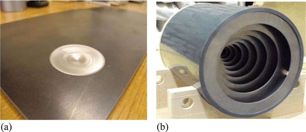
ABH: (a) 2D; (b) 3D.
2.1 Propagation characteristics of one-dimensional (1D) acoustic black hole
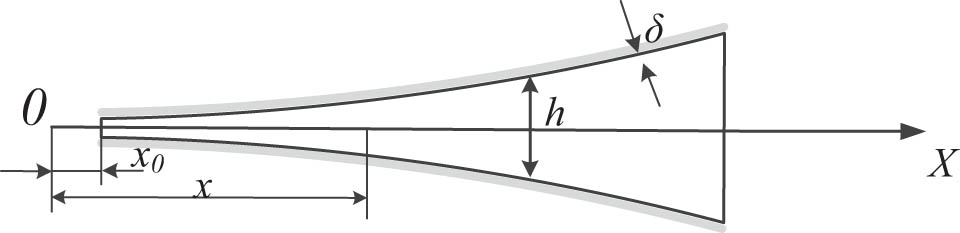
Taking the simplest ABH structure as an example, the structure is shown in Figure 2. Taking the end of the ABH structure as the coordinate origin, the thickness of the black hole structure satisfies the equation h(x) = εx m (m ≥ 2), ε is a constant, and the elastic wave is transmitted to the origin along the negative direction of the x-axis. According to the geometric acoustic theory, the overall wave phase from any point of the ABH section to the coordinate origin is shown in the following equation:

1D ABH.
where k(x) is the bending wave in structure, and the specific value is:
where k p is the wavenumber of symmetric plate wave, c p is the wavenumber of the wave; c t and c l are the wave velocity of the longitudinal wave and shear wave propagating in the structure, respectively. At a specific frequency, k p is a constant. When m ≥ 2, x → 0, k(x) tends to infinity. At this time, the overall wave phase φ is infinite, indicating that at the tip of the structure, the local wavenumber tends to infinity and the wavelength tends to 0. The bending wave can never reach the tip of the structure, and the reflection phenomenon will not occur.
However, the convergence of the ABH tip thickness to zero is difficult to achieve due to the processing limitations. Usually, the ABH structure is truncated at the tip position, so the ideal state of the 1D ABH cannot be realized. At this time, the lower limit of the integration phase of the whole wave is the truncation length x 0 of the ABH. So the 1D ABH tip reflectivity R 0 is as follows:
It can be found that even if the tip position of the ABH model is truncated to a very small length, the value of reflectivity R 0 will reach 50–70%, and the non-reflection characteristics of the ABH will be greatly reduced. The adverse effects caused by the truncation of the tip of the model are usually added to the damping material with a thickness of Δ at the tip of the structure. In order to explore the influence of the damping layer on the vibration characteristics of ABH structure, symmetric and asymmetric ABH structures with additional damping materials are considered, as shown in Figures 2 and 3. In practice, the symmetrical ABH structure requires complex cutting on both sides at the same time, and the damping layer can be selectively attached to the flat side, so in practice, it is more inclined to the asymmetric ABH structure with additional damping material in Figure 4.
Symmetrical ABH structure with damping material.

Asymmetric ABH structure with additional damping material.
First, the thin damping layer is analyzed, considering only the energy attenuation characteristics of the damping layer structure, the bending deformation and longitudinal displacement in the plate satisfy the following equation.
Then, the physical properties of damping materials are analyzed, and it is considered that the physical properties of damping materials are linearly related to the frequency, and the dimensionless constant ν is defined as the energy loss factor. A damping material with a thickness of Δ is attached on both sides of a plate with a thickness of h, and the additional loss factor is shown below.
In the equation, ν is the loss factor of the damping material itself, E
1 and E
2 are the elastic modulus of ABH plate material and damping material, respectively. Considering that the thickness of damping material is small enough to satisfy
The damping material is attached to the two sides of the symmetrical ABH structure, and the imaginary part of the bending wave propagation wavenumber in the structure is expressed as follows:
where h(x) is the local thickness of the ABH structure, and η is the loss factor of the main structure of the ABH. When the thickness of the ABH structure conforms to the quadratic power function, h(x) = εx 2, the reflection coefficient R 0 of the tip of the ABH structure with thin damping material can be obtained by introducing equation (9).
For the ABH structure with unilateral additional damping material, the expression form of the reflection coefficient is consistent with equation (11), and only μ is replaced by the following equation:
2.2 Propagation characteristics of 2D acoustic black hole
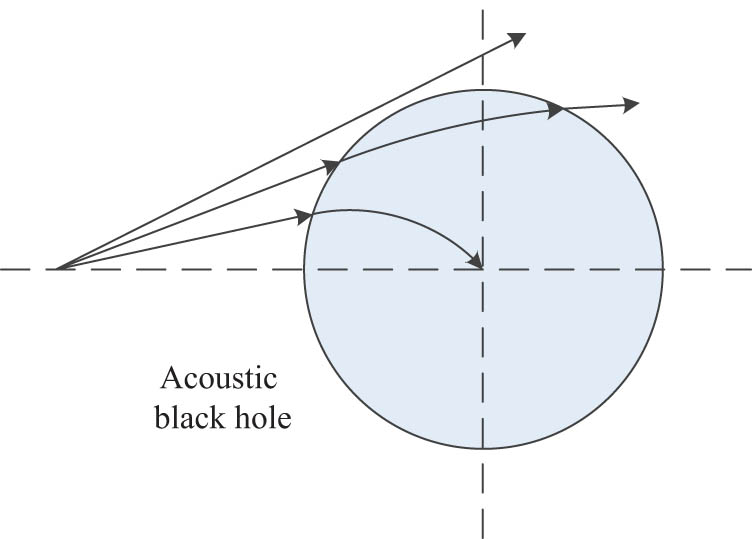
For the rectangular plate of 2D ABH structure shown in Figure 5, the polar coordinate system is established with the center of ABH as the origin of coordinate, and the propagation path of bending wave in the structure can be expressed in the following form.

Polar coordinate diagram.
In the equation, α is the angle between the propagation vector of the bending wave and the coordinate axis r in the polar coordinate system, n(r) is the refractive index of the bending wave in the ABH region, and the refractive index n(r) can be expressed as
where p is the newly introduced parameter to describe the trajectory of bending waves with different incident angles. For rectangular plates without black hole structure, given parameters r
0 and α
0, the propagation trajectory of the bending wave is a straight line. But for rectangular plates with 2D ABHs, the trajectory will no longer be a straight line. When the thickness of the ABH plate satisfies
Propagation trajectory of bending wave.
The above bending wave propagation trajectory only appears in the ideal ABH structure. However, it is difficult to realize the structure with zero center thickness in practical engineering. Researchers usually cut in a certain area of the center of the ABH structure and replace it with an equal thickness circular plate, as shown in Figure 7.

Tip-truncated ABH structure.
The thickness variation of structural plate satisfies the following equation:
For thin plate
where w is the transverse displacement of the plate, D is the bending stiffness of the structure, E is Young’s modulus of the structure, ν is Poisson’s ratio, ρ is the material density, and ω is the circular frequency. Based on the theory of geometric acoustics, the solution of equation (19) is as follows.
Bringing equation (18) into equation (21), ignoring the second-order small quantity, the bending wave path function equation shown in equation (22) is obtained.
where

Black-hole propagation trajectory.
Suppose that r(s) is the position vector of a point on the curved wave ray propagation trajectory and ds is the different segment of the point trajectory (Figure 8); then, equation (22) can be rewritten as follows:
Simultaneous derivation on both sides of the equal sign leads to the propagation trajectory equation of the flexural wave:
Through the above derivation and combined with previous research results, it can be found that for the 2D ABH structure with tip truncation, although the bending wave cannot be perfectly aggregated at the center of the ABH, it still has a certain aggregation effect on the bending wave. The aggregation effect is related to the structural characteristic parameters of the ABH structure, including the power–law relationship between the model truncation length and the model thickness. As the model truncation length increases, the aggregation effect of the ABH structure weakens, and the tip truncation will have a negative impact on the damping effect of the ABH structure.
3 Numerical results and discussion
3.1 Simplified method of acoustic black hole modeling
The thickness of ABH structure conforms to a specific power–law relation. The thickness of each part in the ABH area is not the same, and the surface element cannot be used for modeling and analysis. However, the solid element modeling will lead to a huge calculation scale and seriously affect the analysis efficiency. Therefore, the manuscript used a modeling simplification method (step simplification method) of ABH structure to improve the speed of simulation calculation of ABH structure.
The ABH region is evenly divided into finite intervals of length L, and each interval is simplified to the same thickness d. At this time, surface elements with different thickness attributes can be used to model the ABH structure. Figures 9 and 10 are the process of model simplification for the 1D ABH using this idea. For the modeling of 2D ABHs, the ladder simplification method is also applicable, and 2D ABHs are composed of finite rings with different thicknesses.

1D ABH model (before simplification).

1D ABH model (after simplification).
3.2 Validation of simplification method
In order to verify the effectiveness of the stepped simplified modeling method of ABH, a set of FEMs before and after the simplification of different ABH structures are established. Based on ABAQUS finite element calculation environment, the vibration modes and vibration responses before and after the simplification of the ABH model are compared, and the differences before and after the simplification of the model are analyzed to determine the effectiveness of the simplified method.
3.2.1 Comparative analysis of vibration modes before and after simplification
The difference between the simplified model and the original model in terms of vibration characteristics is compared and analyzed. The calculation models of the 2D ABH shown in Figure 11 are set. The mesh with the same size is used to discrete the model. Since the simplified model is a surface element model, the number of meshes is significantly less than that of the solid element model before simplification, which significantly improves the computational efficiency of the ABH model.
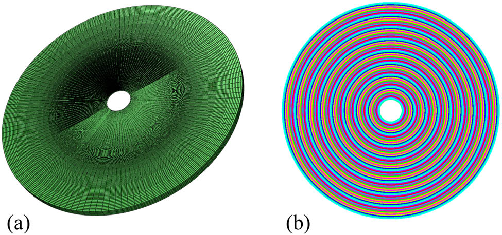
FEM before and after simplification of ABH: (a) 2D ABH model before simplification (273,451 elements); (b) 2D ABH model after simplification (31,564 elements).
The radius of ABH is 100 mm. The thickness of ABH accords with function
Comparison of vibration modes before and after simplification of 2D ABH
| Modes | Before simplification | After simplification | Error (%) |
|---|---|---|---|
| 1st |

|

|
2.9 |
| 381.0 Hz | 391.9 Hz | ||
| 2nd |

|

|
3.0 |
| 619.5 Hz | 638.3 Hz | ||
| 3rd |

|

|
1.8 |
| 963.5 Hz | 981.2 Hz | ||
| 4th |

|
|
2.9 |
| 1061.3 Hz | 1092.1 Hz |
By analyzing the first four modal shapes and natural frequencies of the 2D ABH before and after simplification, it can be found that they are in good agreement, and the calculation error of natural frequency is controlled by 3.0%. It is enough to illustrate that the simplified 2D ABH model can effectively simulate the vibration characteristics of the original structure. It is effective to simplify the ABH by the ladder simplification method.
3.2.2 Comparative analysis of vibration response before and after simplification
In order to further verify the effectiveness of the simplified ABH model, the comparative analysis of the vibration response of the model before and after simplification is carried out. Considering the calculation cost and efficiency, the 1D ABH is taken as the research object to establish the calculation model of 1D ABH as shown in Figure 12. The model is 290 mm long, 50 mm wide, 6 mm thick, and the total length of ABH area is 90 mm. Structural thickness follows the change of h(r) = 6r 2/10,000 power exponential function. Apply a unit force at point P 0 on the centerline of the length direction of the ABH model at a distance of 50 mm to the right. At the same time, observation points P 1, P 2, and P 3 are set as in Figure 13.

1D ABH model.

The location of loading points and observation points.
Based on the stepped simplification method of the ABH, the 1D ABH solid element model and shell element model are established, respectively. We made an evaluation of the vibration response difference before and after the model simplification under the action of unit force (Figure 14).
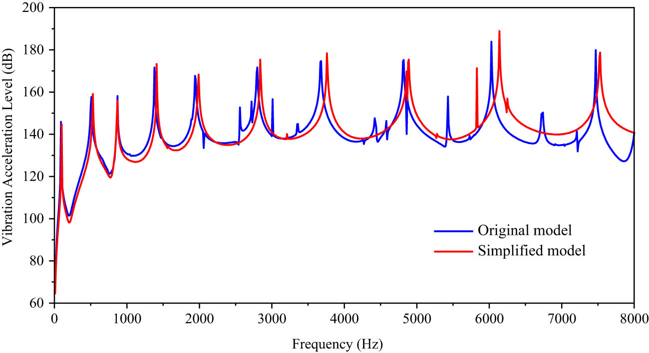
Average vibration acceleration level of observation points.
We can find that, in the frequency range of 10–2,000 Hz, the peak frequency is basically consistent, and the peak value difference is 1–3 dB. In the middle- and high-frequency range above 2,000 Hz, due to the difference in natural frequency, the peak value of vibration response deviates to a certain extent. The frequency error corresponding to the peak value is less than 3.0%, and the difference between the peak value is controlled within 5 dB. On the whole, the simplified model can better reflect the vibration characteristics of the original model. Especially in the low-frequency range, the average vibration acceleration level curves of the calculation model before and after simplification are in good agreement; the effectiveness of the method is verified.
3.3 Influence of 2D ABH characteristic parameters on structural vibration
The ABH structure has the effect of bending wave aggregation and dissipation and can suppress structural vibration. But the vibration suppression effect is affected by many parameters such as cutoff length, damping material parameters, and ABH size. Based on the step simplification method, this section explores the influence of various parameters of the 2D ABH on the vibration characteristics of typical raft structures.
In order to simplify the description method of the ABH structure, the truncated ABH parameters are defined. Since the 2D ABH is obtained by 1D ABH rotating around the structural tip for one week. The 1D ABH is easy to describe, and the parameters of the 1D ABH are defined.
It is shown in Figure 15 that L is the length of the perfect ABH structure, D is the maximum thickness of the ABH, L
0 is the truncated length of the ABH tip, and L
n
and D
n
are the length and thickness of the damping layer. On this basis, the following dimensionless parameters are defined: ABH tip truncation ratio

1D ABH parameters after truncation.
The raft mainly includes the main structures such as the upper panel, the lower panel, the vertical support panel connecting the upper and lower panels, and the isolator connection panel. Usually, in order to reduce the overall height of the raft structure, the upper and lower isolator connection panels are placed between the upper and lower panels. As shown in Figure 16, the upper and lower panels of the raft are 680 mm in length, 580 mm in width, and 11 mm in thickness. The thickness of the vertical support plate is 12 mm. The thickness of the upper isolator connection plate is 18 mm. The thickness of the lower isolator connection plate is 11 mm. The overall height of the raft is 400 mm. The whole raft is made of Q235 marine steel.

Typical raft structure: (a) geometric model; (b) FEM.
Combined with the isolator installation method, four unit-force excitation points are set at the upper vibration isolator panel, and the center point of the lower vibration isolator panel is set as the vibration acceleration observation point. The shell181 element is used to discrete the typical raft structure, with a total of 19,061 elements.
3.3.1 Vibration response analysis of typical raft structure
First, the vibration response of a typical raft structure without the ABH is calculated, and it is used as the comparison benchmark for subsequent structural calculation. Apply the unit force at the excitation point to extract the vibration acceleration response at the observation point, as shown in Figure 17.
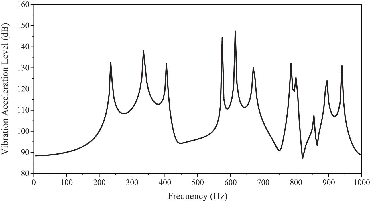
Vibration response of typical raft structure.
It can be seen from the figure that the vibration response of the connecting position of the lower isolator has multiple peaks in the frequency domain of 1,000 Hz. The corresponding peak frequencies before 500 Hz are 235, 335, and 405 Hz. The maximum vibration acceleration level appears at 615 Hz, and the peak value is 147.4 dB. The vibration response diagrams at some frequencies are as follows (Figue 18).

Vibration response diagram: (a) 335 Hz; (b) 615 Hz.
3.3.2 Influence of tip truncation ratio on vibration of typical raft structure
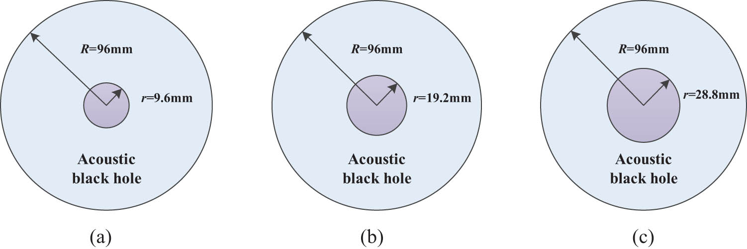
In the practical application of ABH, it will be truncated at a certain length position and filled with steel plates of the same thickness as the truncated surface, so as to ensure the thickness continuity. To investigate the effect of the tip cutoff ratio of the ABH structure on the vibration reduction performance of the structure, as shown in Figure 19, a 2D ABH is placed at the center of the lower isolator support plate. The radius of the ABH is 96 mm, and the ABH tip truncation ratios λ = 10%, λ = 15%, and λ = 20% are set to carry out calculation and analysis.
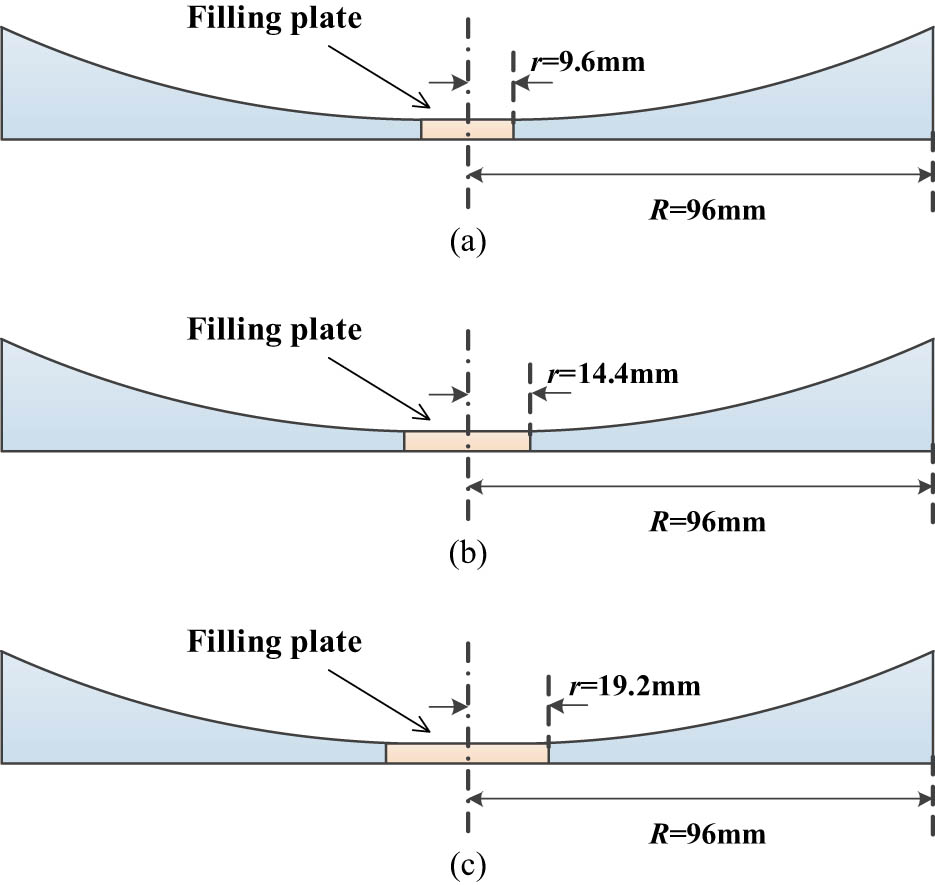
Truncation ratio analysis model of ABH tip: (a) λ = 10%, (b) λ = 15%, and (c) λ = 20%.
The calculation results are shown in Figure 20. In order to reflect the difference in results clearly, we draw the figure in the range of 500–700 Hz. Due to the truncation of the model tip, the structural change is reflected in the overall weight, resulting in the lag of the peak frequency. The truncation part is relatively small in the overall structure quality, and the offset of peak frequency is limited. The three cutoff ratios models can effectively reduce most of the peak values of vibration response within 1,000 Hz and show the rule that the vibration reduction effect of the ABH structure increases with the decrease of λ. The main peak damping effect is shown in Table 2. Where f is the peak frequency, and Δ is the difference in vibration response between the model with different tip truncation ratios and the original model.
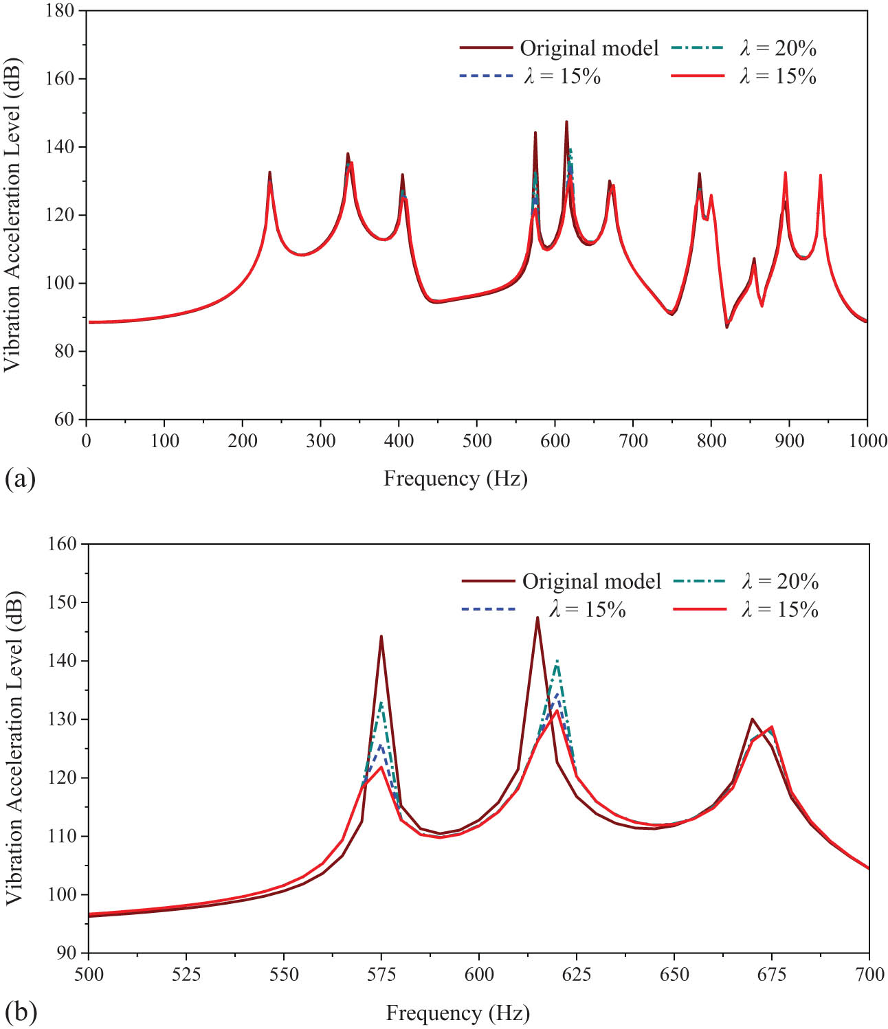
Vibration acceleration level figure: (a) 10–1,000 Hz; (b) 500–700 Hz.
Response of peak damping effect under different tip truncation ratios (dB)
| Peak frequency (Hz) | Original model | λ = 10% | λ = 15% | λ = 20% | |||
|---|---|---|---|---|---|---|---|
| Value | Δ | Value | Δ | Value | Δ | ||
| 235 | 132.6 | 129.6 | 3.0 | 130.2 | 2.4 | 130.6 | 2.0 |
| 335 | 138.1 | 135.4 | 2.7 | 136.3 | 1.8 | 136.8 | 1.3 |
| 405 | 131.9 | 125.0 | 6.9 | 125.7 | 6.2 | 127.0 | 4.9 |
| 575 | 144.2 | 121.8 | 22.4 | 125.9 | 18.3 | 133.0 | 11.2 |
| 615 | 147.4 | 131.5 | 15.9 | 134.4 | 13.0 | 140.0 | 7.4 |
| 670 | 130.1 | 128.7 | 1.4 | 128.5 | 1.6 | 128.1 | 2.0 |
| 785 | 132.2 | 126.9 | 5.3 | 127.4 | 4.8 | 127.9 | 4.3 |
| 940 | 131.2 | 131.8 | −0.6 | 131.7 | −0.5 | 131.7 | −0.5 |
The table shows that when

Typical raft structure vibration (615 Hz): (a) original model; (b) λ = 10%.
3.3.3 Influence of damping length ratio on vibration of typical raft structure.
Damping performance of ABH is greatly reduced due to tip truncation. Therefore, we attach the damping material at the center to realize energy absorption and consumption. To investigate the effect of the ABH damping length ratio on the damping performance of ABHs, the damping material is added at the center of the ABH, and three ABH models with damping length ratios
Different damping length ratio models of the ABH: (a) φ = 10%, (b) φ = 20%, and (c) φ = 30%.
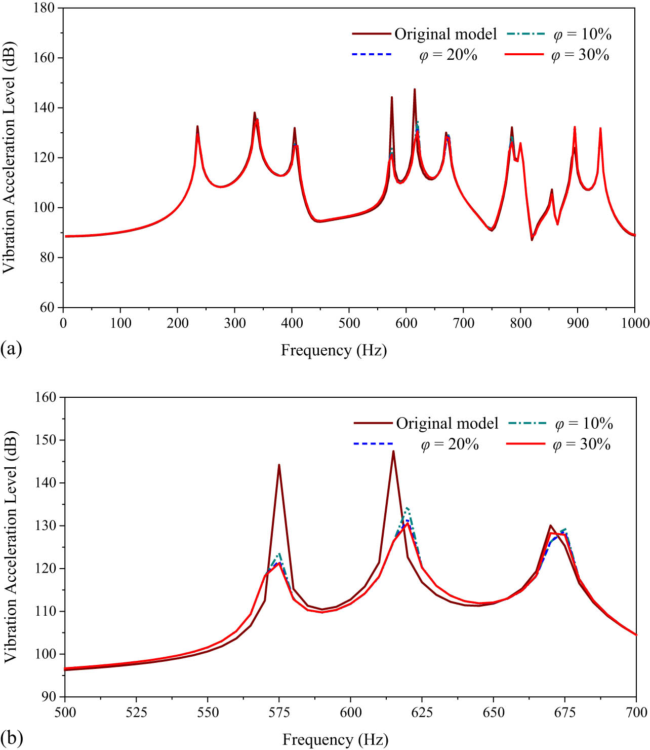
Vibration acceleration level figure: (a) 10–1000 Hz; (b) 500–700 Hz.
It can be seen from the vibration acceleration level curve that when the damping material replaces the original steel structure, the overall physical characteristics of the structure have changed and are reflected in the peak frequency. What is more, the response of the three damping length ratio models is consistent with the trend of frequency change within 1,000 Hz and can effectively reduce the vibration of the observation point. In a certain range, the damping effect of ABH structure gradually improves as the damping length ratio increases. Table 3 shows the peak damping effect of the ABH response curves with different damping length ratios. Here, f is the peak frequency, and Δ is the difference of response between the model with different tip truncation ratios and the original model.
Response of peak damping effect under different damping length ratios (dB)
| Peak frequency (Hz) | Original model | φ = 10% | φ = 20% | φ = 30% | |||
|---|---|---|---|---|---|---|---|
| Value | Δ | Value | Δ | Value | Δ | ||
| 235 | 132.6 | 130.1 | 2.5 | 129.6 | 3.0 | 129.4 | 3.2 |
| 335 | 138.1 | 135.8 | 2.3 | 135.4 | 2.7 | 135.3 | 2.8 |
| 405 | 131.9 | 125.8 | 6.1 | 125.0 | 6.9 | 124.7 | 7.2 |
| 575 | 144.2 | 123.6 | 20.6 | 121.8 | 22.4 | 121.2 | 23.0 |
| 615 | 147.4 | 134.6 | 12.8 | 131.5 | 15.9 | 130.6 | 16.8 |
| 670 | 130.1 | 129.5 | 0.6 | 128.7 | 1.4 | 128.2 | 1.9 |
| 785 | 132.2 | 128.9 | 3.3 | 126.9 | 5.3 | 126.1 | 6.1 |
| 940 | 131.2 | 131.8 | −0.6 | 131.8 | −0.6 | 131.8 | −0.6 |
When the damping length ratio φ = 20%, the damping effect of the ABH can reach 3–7 dB at most frequency points, and the damping effect can reach more than 20 dB at some frequency points. Comparing the model calculation results of three different damping length ratios, the damping effect is optimal at φ = 30%, but the damping effect is not much different from that at φ = 20%, so the excessive increase in damping length does not improve the damping effect significantly.
3.3.4 Influence of damping thickness ratio on vibration of typical raft structure.
In this section, the influence of the damping thickness ratio on the damping performance of ABH is investigated by changing the damping thickness ratio of the ABH set at the center of the lower isolator support plate. Three calculation models of damping thickness ratios µ = 10%, µ = 20%, and µ = 30% (Figure 24) are set to carry out the calculation and analysis.

Different damping thickness ratio models of the ABH: (a) μ = 10%, (b) μ = 20%, and (c) μ = 30%.
Figure 25 shows the vibration acceleration response results in the frequency range of 1,000 Hz. The frequency corresponding to the main peak is related to the natural frequency of the structure. It can be found that the ABHs with three damping thickness ratios can effectively reduce the vibration response of the main peak. And the damping effect of the ABH structure increases with the increase in damping thickness ratio. Table 4 shows the damping effect of the three damping thickness ratio conditions.

Vibration acceleration level figure: (a) 10–1,000 Hz; (b) 500–700 Hz.
Response of peak damping effect under different damping thickness ratios (dB)
| Peak frequency (Hz) | Original model | μ = 10% | μ = 20% | μ = 30% | |||
|---|---|---|---|---|---|---|---|
| Value | Δ | Value | Δ | Value | Δ | ||
| 235 | 132.6 | 131.2 | 1.4 | 129.6 | 3.0 | 128.4 | 4.2 |
| 335 | 138.1 | 136.6 | 1.5 | 135.4 | 2.7 | 134.5 | 3.6 |
| 405 | 131.9 | 127.7 | 4.2 | 125 | 6.9 | 123.6 | 8.3 |
| 575 | 144.2 | 127 | 17.2 | 121.8 | 22.4 | 118.9 | 25.3 |
| 615 | 147.4 | 136.1 | 11.3 | 131.5 | 15.9 | 130.2 | 17.2 |
| 670 | 130.1 | 128.8 | 1.3 | 128.7 | 1.4 | 128.5 | 1.6 |
| 785 | 132.2 | 128.7 | 3.5 | 126.9 | 5.3 | 126 | 6.2 |
| 940 | 131.2 | 131.7 | −0.5 | 131.8 | −0.6 | 131.6 | −0.4 |
By comprehensively comparing the model calculation results under three different damping thickness ratios, it is found that the damping effect is the best when μ = 30%. However, an excessive increase in damping thickness does not significantly improve the damping effect.
3.3.5 Influence of power exponent m on vibration of typical raft structure
It can be seen from the previous discussion that ABH thickness follows power law
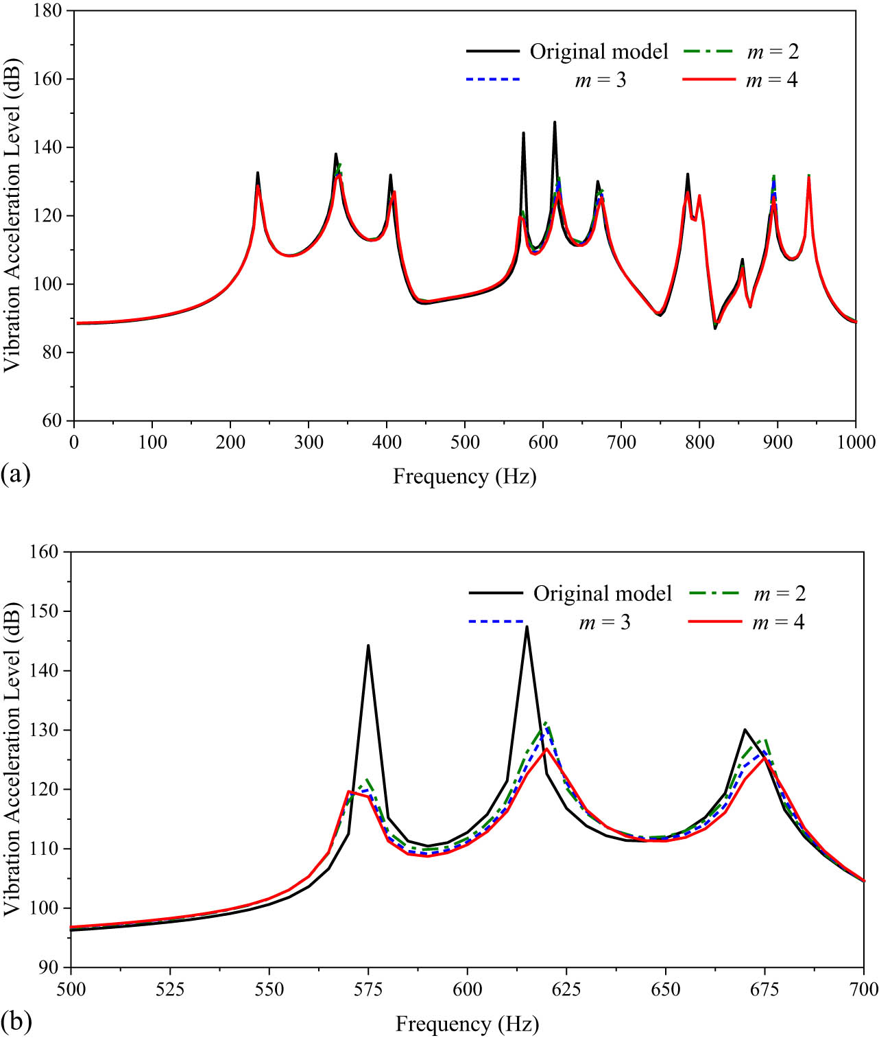
Vibration acceleration level figure: (a) 10–1,000 Hz; (b) 500–700 Hz.
Most peak vibration responses can be effectively reduced in the frequency range of 1,000 Hz regardless of power exponent. At the same time, it can be found that with the increase in m, the vibration reduction effect of the ABH structure is better. Table 5 shows the peak damping effect of the ABH response curves.
Response of peak damping effect under different power exponents (dB)
| Peak frequency (Hz) | Original model | m = 2 | m = 3 | m = 4 | |||
|---|---|---|---|---|---|---|---|
| Value | Δ | Value | Δ | Value (Hz) | Δ | ||
| 235 | 132.6 | 129.6 | 3.0 | 129.1 | 3.5 | 128.8 | 3.8 |
| 335 | 138.1 | 135.4 | 2.7 | 132.4 | 3.0 | 131.9 | 3.5 |
| 405 | 131.9 | 125.0 | 6.9 | 126.0 | 5.9 | 127.0 | 4.9 |
| 575 | 144.2 | 121.8 | 22.4 | 119.9 | 24.3 | 118.8 | 25.4 |
| 615 | 147.4 | 131.5 | 15.9 | 130.1 | 17.3 | 126.8 | 20.6 |
| 670 | 130.1 | 128.7 | 1.4 | 126.5 | 3.6 | 125.3 | 4.8 |
| 785 | 132.2 | 126.9 | 5.3 | 127.3 | 4.9 | 126.8 | 5.4 |
| 940 | 131.2 | 131.8 | −0.6 | 131.6 | −0.4 | 131.2 | 0 |
When the power exponent m = 2 and m = 3, the vibration reduction effect at most frequencies can reach 3–7 dB, and the vibration reduction effect at some frequencies can reach more than 20 dB. When m = 4, most of the peak damping effect is only about 1 dB higher than that of m = 3, and the vibration reduction effect is not significantly improved.
3.4 Application of two-dimensional the acoustic black hole in raft
According to the discussion and analysis above, the optimal solution of each parameter of the ABH in the practical application process is obtained. In this section, the optimal parameters are applied to the raft, and the application of the ABH in the raft is studied.
3.4.1 Calculation model of raft structure
In order to carry out the influence of the application of the ABHs on the vibration characteristics of raft structure, the raft model is first established as shown in Figure 27. The main scale of the raft structure is 1,000 mm × 1,500 mm × 300 mm, and the thickness of the panel is 14 mm. Four columns and three rows of vertical support webs were set with a thickness of 12 mm and spacing of 500 mm. The structural materials were all Q235 marine steel.

Calculation model of raft structure: (a) geometric model; (b) FEM.
We developed the finite element simulation model based on the geometric model. Combined with the actual installation of the raft, four unit-force excitation points are set on its upper surface, and 10 observation points are selected on its lower surface.
According to the above calculation and analysis, taking λ = 10%, φ = 20%, μ = 20%, and m = 2 as the main parameters of the ABH. According to the size of the raft vertical support plate, the radius of the ABH is determined to be 120 mm, and the ABH tip is cut within 12 mm. The length of the damping layer is 24 mm, and the thickness is 2.4 mm. Embed the ABH into the raft structure, as shown in Figure 28.
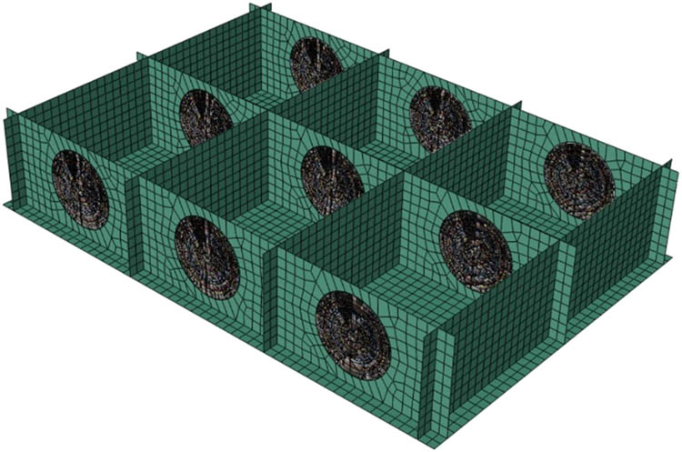
FEM of raft structure with ABHs.
3.4.2 Vibration analysis of the acoustic black hole raft structure
Figure 29 shows the vibration response curve of the raft structure in the frequency range of 1,000 Hz. In general, the vibration acceleration curves of the observation points of the two models increase with the increase in frequency and are relatively smooth within 300 Hz, followed by obvious fluctuations. Compared with the original model, the vibration response of the raft observation point decreases to varying degrees after embedding the ABH. The embedded ABH has little effect on the vibration characteristics of the structure in the frequency range of 300–400 Hz, and the peak value decreases by about 2–3 dB. In the frequency domain range of 500–1,000 Hz, compared with the original model, the peak frequency changes greatly, and there is a significant deviation. Most peaks are reduced, and the decline amplitude can reach more than 10 dB.
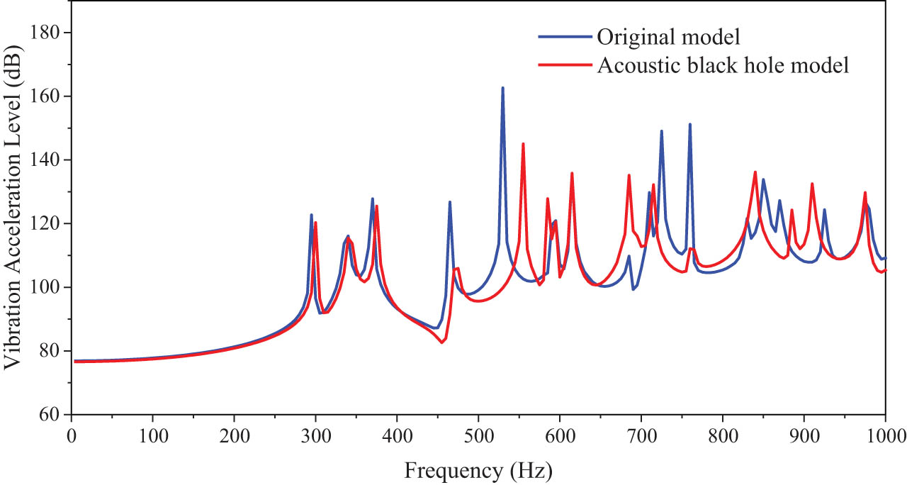
Vibration acceleration-level figure.
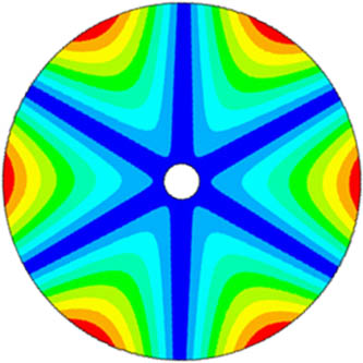
From the vibration response image of some frequency points, it can be found that there is an obvious energy aggregation effect at the center of the ABH. By adding damping materials at the center of the ABH, the energy gathered in the center of the structure is dissipated, and the vibration response is greatly attenuated. It is proved that the ABH has the effect of suppressing structural vibration, and the raft embedded with the ABH has an obvious improvement in vibration reduction performance (Figure 30).

Vibration response diagram: (a) f = 305 Hz; (b) f = 375 Hz; and (c) f = 555 Hz.
4 Conclusion
In this article, the vibration characteristics of the typical raft structure of the ABH are studied. The propagation characteristics of the ABH are briefly introduced based on geometric acoustic theory. The influence of various parameters of the ABH on the vibration characteristics is studied, and the optimal values of parameters are obtained. In addition, the dynamic performance analysis of the raft structure is carried out. The following conclusions are drawn:
The ladder simplification method is applied to the ABH modeling, which can greatly improve computational efficiency. Compared with the original model, the natural frequency error is less than 3%, and the vibration response curve is in good agreement. The method is effective and feasible.
When the cutoff ratio of the ABH tip λ = 10%, damping length ratio φ = 20%, damping thickness ratio μ = 20%, and power exponent m = 2 or 3, better results can be obtained in both actual processing and vibration performance.
The optimal value of the main parameters of the ABH is applied to the raft structure so that the average vibration response peak of the raft is significantly reduced, especially if the vibration acceleration level in the frequency domain above 500 Hz is reduced by about 10 dB, which significantly improves the vibration isolation performance of the structure.
The ABH can effectively reduce the vibration response of typical raft structure and has broad application prospects in the field of ship vibration isolation devices.
Acknowledgments
This research was supported by Harbin Engineering University, China Ship Research and Development Academy and Marine Design and Research Institute of China.
-
Funding information: This study was funded by the National Natural Science Foundation of China (Grant Numbers. 52101351 and U2006229).
-
Author contributions: Five authors have made irreplaceable work on this paper. Yang Tang provided theoretical support and research ideas. Jiangtao Liu analyzed the data and complete the corresponding chapter. Liu Ning modified and improved the manuscript. Fuzhen Pang provided necessary guidance. Yu Wang performed the simulation.
-
Conflict of interest: Authors state no conflict of interest.
References
[1] Vo, N., M. K. Nguyen, and T. D. Le. Analytical study of a pneumatic vibration isolation platform featuring adjustable stiffness. Communications in Nonlinear Science and Numerical Simulation, Vol. 98, No. 23, 2021, id. 105775.10.1016/j.cnsns.2021.105775Search in Google Scholar
[2] Xiong, F., Y. Li, and W. Chun. Review on vibration isolation technology. Journal of Physics: Conference Series, Vol. 1820, No. 1, 2021, id. 012009.10.1088/1742-6596/1820/1/012009Search in Google Scholar
[3] Gao, M., G. Xu, T. Y. Liu, W. C. Tang, J. L. Wen, and S. X. Li. Vibration control of a marine centrifugal pump using floating raft isolation system. Journal of Low Frequency Noise, Vibration and Active Control, Vol. 39, 2019, id. 146134841984302.10.1177/1461348419843024Search in Google Scholar
[4] Tang, S., S. Liu, D. Zhao, X. Ren, W. Zhang, and Y. Liu. Vibration response analysis of plate with microfloating raft arrays under multi-point random excitation. Archive of Applied Mechanics, Vol. 91, No. 10, 2021, pp. 4081–4096.10.1007/s00419-021-02028-7Search in Google Scholar
[5] Wang, H., Z. Y. Weng, G. Xiang, B. Lu, H. G. Ding, and H. W. You. The vibration isolation effect research of the floating raft isolation system based on the adjustable flexibility of foundation. Advanced Materials Research, Vol. 819, 2013, pp. 115–119.10.4028/www.scientific.net/AMR.819.115Search in Google Scholar
[6] Fang, Y., Y. Zuo, and Z. Xia. Study on design method and vibration reduction characteristic of floating raft with periodic structure. IOP Conference Series. Materials Science and Engineering, Vol. 322, No. 4, 2018, id. 042025.10.1088/1757-899X/322/4/042025Search in Google Scholar
[7] Muhammad, C. W. Lim, From Photonic Crystals to Seismic Metamaterials: A Review via Phononic Crystals and Acoustic Metamaterials. Archives of Computational Methods in Engineering, Vol. 29, No.2, 2022, pp. 1137–1198.10.1007/s11831-021-09612-8Search in Google Scholar
[8] Martínez-Sala, R., J. Sancho, J. V. Sánchez, V. Gómez, J. Llinares, and F. Meseguer. Sound attenuation by sculpture. Nature, Vol. 378, No. 6554, 1995, pp. 241–241.10.1038/378241a0Search in Google Scholar
[9] Sigalas, M. M. and E. N. Economou. Elastic and acoustic wave band structure. Journal of Sound and Vibration, Vol. 158, No. 2, 1992, pp. 377–382.10.1016/0022-460X(92)90059-7Search in Google Scholar
[10] Liu, Z., X. Zhang, Y. Mao, Y. Y. Zhu, Z. Yang, C. T. Chan, et al. Locally resonant sonic materials. Science, Vol. 289, No. 5485, 2000, pp. 1734–1736.10.1126/science.289.5485.1734Search in Google Scholar PubMed
[11] Sigalas, M. M. and C. M. Soukoulis. Elastic-wave propagation through disordered and/or absorptive layered systems. Physical Review B: Condensed Matter, Vol. 51, No. 5, 1995, pp. 2780–2789.10.1103/PhysRevB.51.2780Search in Google Scholar PubMed
[12] Wu, F., Z. Liu, and Y. Liu. Acoustic band gaps in 2D liquid phononic crystals of rectangular structure. Journal of Physics. D, Applied Physics, Vol. 35, No. 2, 2001, pp. 162–165.10.1088/0022-3727/35/2/309Search in Google Scholar
[13] Sigalas, M. M. and A. Garc. Theoretical study of three dimensional elastic band gaps with the finite-difference time-domain method. Journal of Applied Physics, Vol. 87, No. 6, 2000, pp. 3122–3125.10.1063/1.372308Search in Google Scholar
[14] Krylov, V. V. and A. L. Shuvalov. Propagation of localised flexural vibrations along plate edges described by a power law. Institute of Acoustics, Vol. 22, 2000, pp. 263–270.Search in Google Scholar
[15] Krylov, V. V. and F. Tilman. Acoustic ‘black holes’ for flexural waves as effective vibration dampers. Journal of Sound and Vibration, Vol. 274, No. 3–5, 2004, pp. 605–619.10.1016/j.jsv.2003.05.010Search in Google Scholar
[16] Krylov, V. V. and R. Winward. Experimental investigation of the acoustic black hole effect for flexural waves in tapered plates. Journal of Sound and Vibration, Vol. 300, No. 1–2, 2007, pp. 43–49.10.1016/j.jsv.2006.07.035Search in Google Scholar
[17] Georgiev, V. B., J. Cuenca, F. Gautier, L. Simon, and V. V. Krylov. Damping of structural vibrations in beams and elliptical plates using the acoustic black hole effect. Journal of Sound and Vibration, Vol. 330, No. 11, 2011, pp. 2497–2508.10.1016/j.jsv.2010.12.001Search in Google Scholar
[18] Tang, L., L. Cheng, H. Ji, and J. Qiu. Characterization of acoustic black hole effect using a one-dimensional fully-coupled and wavelet-decomposed semi-analytical model. Journal of Sound and Vibration, Vol. 374, 2016, pp. 172–184.10.1016/j.jsv.2016.03.031Search in Google Scholar
[19] Zeng, P., L. Zheng, J. Deng, A. Elsabbagh, S. Xiang, T. Yan, et al. Flexural wave concentration in tapered cylindrical beams and wedge-like rectangular beams with power-law thickness. Journal of Sound and Vibration, Vol. 452, 2019, pp. 82–96.10.1016/j.jsv.2019.04.002Search in Google Scholar
[20] Deng, J., L. Zheng, P. Zeng, Y. Zuo, and O. Guasch. Passive constrained viscoelastic layers to improve the efficiency of truncated acoustic black holes in beams. Mechanical Systems and Signal Processing, Vol. 118, 2018, pp. 461–476.10.1016/j.ymssp.2018.08.053Search in Google Scholar
[21] Deng, J., O. Guasch, and L. Zheng. Ring-shaped acoustic black holes for broadband vibration isolation in plates. Journal of Sound and Vibration, Vol. 458, 2019, pp. 109–122.10.1016/j.jsv.2019.06.017Search in Google Scholar
[22] Deng, J., O. Guasch, L. Maxit, and L. Zheng. Vibration of cylindrical shells with embedded annular acoustic black holes using the Rayleigh-Ritz method with Gaussian basis functions. Mechanical Systems and Signal Processing, Vol. 150, 2021, id. 107225.10.1016/j.ymssp.2020.107225Search in Google Scholar
[23] Gao, N., B. Wang, K. Lu, and H. Hou. Complex band structure and evanescent Bloch wave propagation of periodic nested acoustic black hole phononic structure. Applied Acoustics, Vol. 177, No. 3, 2021, id. 107906.10.1016/j.apacoust.2020.107906Search in Google Scholar
[24] Sheng, H., M.-X. He, X.-F. Lyu, and Q. Ding. Ultra-low frequency broadband gap optimization of 1D periodic structure with dual power-law acoustic black holes. Journal of Intelligent Material Systems and Structures, 2021, id. 1045389X211018841.10.1177/1045389X211018841Search in Google Scholar
[25] Conlon, S. C., J. B. Fahnline, and F. Semperlotti. Numerical analysis of the vibroacoustic properties of plates with embedded grids of acoustic black holes. Journal of the Acoustical Society of America, Vol. 137, No. 1, 2015, pp. 447–457.10.1121/1.4904501Search in Google Scholar PubMed
[26] Bowyer, E. P. and V. V. Krylov. Slots of power-law profile as acoustic black holes for flexural waves in metallic and composite plates. Structures, Vol. 6, 2016, pp. 48–58.10.1016/j.istruc.2016.02.002Search in Google Scholar
[27] Yan, S., A. M. Lomonosov, and Z. Shen. Numerical and experimental study of Lamb wave propagation in a two-dimensional acoustic black hole. Journal of Applied Physics, Vol. 119, No. 21, 2016, id. 605.10.1063/1.4953221Search in Google Scholar
[28] Conlon, S. C. and P. A. Feurtado. Progressive phase trends in plates with embedded acoustic black holes. Journal of the Acoustical Society of America, Vol. 143, No. 2, 2018, pp. 921–930.10.1121/1.5024235Search in Google Scholar PubMed
[29] Du, X., D. Huang, Q. Fu, and J. Zhang. Effects of acoustic black hole parameters and damping layer on sound insulation performance of ABH circular plate. Applied Sciences (Basel, Switzerland), Vol. 9, No. 24, 2019, id. 5366.10.3390/app9245366Search in Google Scholar
[30] Pang, F., Y. Qin, H. Li, Y. Teng, Q. Gong, and S. Wang. Study on impact resistance of composite rocket launcher. Reviews on Advanced Materials Science, Vol. 60, No. 1, 2021, pp. 615–630.10.1515/rams-2021-0045Search in Google Scholar
[31] Dehghan, M. and G. H. Baradaran. Buckling and free vibration analysis of thick rectangular plates resting on elastic foundation using mixed finite element and differential quadrature method. Applied Mathematics and Computation, Vol. 218, No. 6, 2011, pp. 2772–2784.10.1016/j.amc.2011.08.020Search in Google Scholar
[32] Gao, C., H. Zhang, H. Li, F. Pang, and H. Wang. Numerical and experimental investigation of vibro-acoustic characteristics of a submerged stiffened cylindrical shell excited by a mechanical force. Ocean Engineering, Vol. 249, 2022, id. 110913.10.1016/j.oceaneng.2022.110913Search in Google Scholar
[33] Avi, E., A. Laakso, J. Romanoff, H. Remes, and I. Lillemäe-Avi. Coarse mesh finite element model for cruise ship global and local vibration analysis. Marine Structures, Vol. 79, No. 4, 2021, id. 103053.10.1016/j.marstruc.2021.103053Search in Google Scholar
[34] Du, Y., D. Jia, H. Li, C. Gao, and H. Wang. A unified method to analyze free and forced vibration of stiffened plates under various edge conditions. Eur J Mechanics – A/Solids, Vol. 94, 2022, id. 104573.10.1016/j.euromechsol.2022.104573Search in Google Scholar
[35] Gao, C., F. Pang, H. Li, D. Jia, and Y. Tang. Steady and transient vibration analysis of uniform and stepped annular/circular plates based on FSDT. Acta Mechanica, Vol. 233, No. 3, 2022, pp. 1061–1082.10.1007/s00707-022-03157-ySearch in Google Scholar
[36] Li, H., F. Pang, X. Miao, Y. Du, and H. Tian. A semi-analytical method for vibration analysis of stepped doubly-curved shells of revolution with arbitrary boundary conditions. Thin-Walled Structures, Vol. 129, 2018, pp. 125–144.10.1016/j.tws.2018.03.026Search in Google Scholar
[37] Pang, F., H. Li, H. Chen, and Y. Shan. Free vibration analysis of combined composite laminated cylindrical and spherical shells with arbitrary boundary conditions. Mechanics of Advanced Materials and Structures, Vol. 28, No. 2, 2021, pp. 182–190.10.1080/15376494.2018.1553258Search in Google Scholar
[38] Li, H., F. Pang, X. Miao, and Y. Li. Jacobi-Ritz method for free vibration analysis of uniform and stepped circular cylindrical shells with arbitrary boundary conditions: A unified formulation. Computers & Mathematics with Applications (Oxford, England), Vol. 77, No. 2, 2019, pp. 427–440.10.1016/j.camwa.2018.09.046Search in Google Scholar
[39] Huang, W., H. Ji, J. Qiu, and L. Cheng. Analysis of ray trajectories of flexural waves propagating over generalized acoustic black hole indentations. Journal of Sound and Vibration, Vol. 417, 2018, pp. 216–226.10.1016/j.jsv.2017.12.012Search in Google Scholar
[40] Kim, S. Y. and D. Lee. Numerical analysis of wave energy dissipation by damping treatments in a plate with acoustic black holes. Journal of Mechanical Science and Technology, Vol. 32, No. 8, 2018, pp. 3547–3555.10.1007/s12206-018-0705-8Search in Google Scholar
© 2022 Yang Tang et al., published by De Gruyter
This work is licensed under the Creative Commons Attribution 4.0 International License.
Articles in the same Issue
- Review Articles
- State of the art, challenges, and emerging trends: Geopolymer composite reinforced by dispersed steel fibers
- A review on the properties of concrete reinforced with recycled steel fiber from waste tires
- Copper ternary oxides as photocathodes for solar-driven CO2 reduction
- Properties of fresh and hardened self-compacting concrete incorporating rice husk ash: A review
- Basic mechanical and fatigue properties of rubber materials and components for railway vehicles: A literature survey
- Research progress on durability of marine concrete under the combined action of Cl− erosion, carbonation, and dry–wet cycles
- Delivery systems in nanocosmeceuticals
- Study on the preparation process and sintering performance of doped nano-silver paste
- Analysis of the interactions between nonoxide reinforcements and Al–Si–Cu–Mg matrices
- Research Articles
- Study on the influence of structural form and parameters on vibration characteristics of typical ship structures
- Deterioration characteristics of recycled aggregate concrete subjected to coupling effect with salt and frost
- Novel approach to improve shale stability using super-amphiphobic nanoscale materials in water-based drilling fluids and its field application
- Research on the low-frequency multiline spectrum vibration control of offshore platforms
- Multiple wide band gaps in a convex-like holey phononic crystal strip
- Response analysis and optimization of the air spring with epistemic uncertainties
- Molecular dynamics of C–S–H production in graphene oxide environment
- Residual stress relief mechanisms of 2219 Al–Cu alloy by thermal stress relief method
- Characteristics and microstructures of the GFRP waste powder/GGBS-based geopolymer paste and concrete
- Development and performance evaluation of a novel environmentally friendly adsorbent for waste water-based drilling fluids
- Determination of shear stresses in the measurement area of a modified wood sample
- Influence of ettringite on the crack self-repairing of cement-based materials in a hydraulic environment
- Multiple load recognition and fatigue assessment on longitudinal stop of railway freight car
- Synthesis and characterization of nano-SiO2@octadecylbisimidazoline quaternary ammonium salt used as acidizing corrosion inhibitor
- Perforated steel for realizing extraordinary ductility under compression: Testing and finite element modeling
- The influence of oiled fiber, freeze-thawing cycle, and sulfate attack on strain hardening cement-based composites
- Perforated steel block of realizing large ductility under compression: Parametric study and stress–strain modeling
- Study on dynamic viscoelastic constitutive model of nonwater reacted polyurethane grouting materials based on DMA
- Mechanical behavior and mechanism investigation on the optimized and novel bio-inspired nonpneumatic composite tires
- Effect of cooling rate on the microstructure and thermal expansion properties of Al–Mn–Fe alloy
- Research on process optimization and rapid prediction method of thermal vibration stress relief for 2219 aluminum alloy rings
- Failure prevention of seafloor composite pipelines using enhanced strain-based design
- Deterioration of concrete under the coupling action of freeze–thaw cycles and salt solution erosion
- Creep rupture behavior of 2.25Cr1Mo0.25V steel and weld for hydrogenation reactors under different stress levels
- Statistical damage constitutive model for the two-component foaming polymer grouting material
- Nano-structural and nano-constraint behavior of mortar containing silica aggregates
- Influence of recycled clay brick aggregate on the mechanical properties of concrete
- Effect of LDH on the dissolution and adsorption behaviors of sulfate in Portland cement early hydration process
- Comparison of properties of colorless and transparent polyimide films using various diamine monomers
- Study in the parameter influence on underwater acoustic radiation characteristics of cylindrical shells
- Experimental study on basic mechanical properties of recycled steel fiber reinforced concrete
- Dynamic characteristic analysis of acoustic black hole in typical raft structure
- A semi-analytical method for dynamic analysis of a rectangular plate with general boundary conditions based on FSDT
- Research on modification of mechanical properties of recycled aggregate concrete by replacing sand with graphite tailings
- Dynamic response of Voronoi structures with gradient perpendicular to the impact direction
- Deposition mechanisms and characteristics of nano-modified multimodal Cr3C2–NiCr coatings sprayed by HVOF
- Effect of excitation type on vibration characteristics of typical ship grillage structure
- Study on the nanoscale mechanical properties of graphene oxide–enhanced shear resisting cement
- Experimental investigation on static compressive toughness of steel fiber rubber concrete
- Study on the stress field concentration at the tip of elliptical cracks
- Corrosion resistance of 6061-T6 aluminium alloy and its feasibility of near-surface reinforcements in concrete structure
- Effect of the synthesis method on the MnCo2O4 towards the photocatalytic production of H2
- Experimental study of the shear strength criterion of rock structural plane based on three-dimensional surface description
- Evaluation of wear and corrosion properties of FSWed aluminum alloy plates of AA2020-T4 with heat treatment under different aging periods
- Thermal–mechanical coupling deformation difference analysis for the flexspline of a harmonic drive
- Frost resistance of fiber-reinforced self-compacting recycled concrete
- High-temperature treated TiO2 modified with 3-aminopropyltriethoxysilane as photoactive nanomaterials
- Effect of nano Al2O3 particles on the mechanical and wear properties of Al/Al2O3 composites manufactured via ARB
- Co3O4 nanoparticles embedded in electrospun carbon nanofibers as free-standing nanocomposite electrodes as highly sensitive enzyme-free glucose biosensors
- Effect of freeze–thaw cycles on deformation properties of deep foundation pit supported by pile-anchor in Harbin
- Temperature-porosity-dependent elastic modulus model for metallic materials
- Effect of diffusion on interfacial properties of polyurethane-modified asphalt–aggregate using molecular dynamic simulation
- Experimental study on comprehensive improvement of shear strength and erosion resistance of yellow mud in Qiang Village
- A novel method for low-cost and rapid preparation of nanoporous phenolic aerogels and its performance regulation mechanism
- In situ bow reduction during sublimation growth of cubic silicon carbide
- Adhesion behaviour of 3D printed polyamide–carbon fibre composite filament
- An experimental investigation and machine learning-based prediction for seismic performance of steel tubular column filled with recycled aggregate concrete
- Effects of rare earth metals on microstructure, mechanical properties, and pitting corrosion of 27% Cr hyper duplex stainless steel
- Application research of acoustic black hole in floating raft vibration isolation system
- Multi-objective parametric optimization on the EDM machining of hybrid SiCp/Grp/aluminum nanocomposites using Non-dominating Sorting Genetic Algorithm (NSGA-II): Fabrication and microstructural characterizations
- Estimating of cutting force and surface roughness in turning of GFRP composites with different orientation angles using artificial neural network
- Displacement recovery and energy dissipation of crimped NiTi SMA fibers during cyclic pullout tests