Performing laboratory study of the behavior of reactive powder concrete on the shear of RC deep beams by the drilling core test
-
Azhar Ayad Jaafar


Abstract
In the past decade, it has been observed that the applications of modern materials have developed a lot, especially effective reactive powder concrete (RPC), due to its superior performance properties. As a result of the superior resistance of RPC, it will give a longer construction life with less maintenance and more resistance to various environmental conditions and exhibits high-performance features such as high porosity, very high strength, and excellent corrosion resistance. The parameters studied in the present research were used to investigate the effect of maximum load, deflection, tensile and strain of concrete, first shear crack, crack pattern, and crack width. Considering the aforesaid cause and objective, one specimen of RPC RC deep beams has a rectangular cross-section of 150 mm in width, 500 mm in depth, and a total length of 1.2 m. One control specimen was tested for comparison. Moreover, 12 control specimens including cylinders and cubes were cast and tested to obtain the mechanical properties of the normal and RPC deep beams. Following the specimens’ processing, they were subjected to two concentrated load pressure tests through a hydraulic jack. Based on the results, the ultimate strength, deflection, and first shear crack capacity for the reactive powder concrete deep beam (RPCDB) have increased by 68, 10.5, and 62.5%, respectively, compared with concrete deep beam (CDB). Moreover, with respect to the width, the delay in the appearance of the first shear crack was reduced by 11 and 78%, respectively, compared with CDB at 65% of the final shear load. In addition, regarding the stress-strain results, RPCDB has increased by 118% at the maximum stress compared with CDB and in contrast, the strain scores for CDB increased by 22.5% at maximum stress compared to RPCDB.
1 Introduction
In recent years, the techniques, and materials for repairing, refurbishing, and reinforcing reinforcement concrete (RC) beams have been widely applied due to their high-performance qualities. Reactive powder concrete (RPC) is a new type of concrete characterized by having particles with a diameter not exceeding 600 mm and with very high compression and tensile strength [1]. Many parameters affect the enclosure efficiency of concrete deep beams with RPC, including concrete strength, deflection, crack pattern, crack width, first crack load, failure load, and mode of failure. It was concluded that ultra high performance fiber reinforced concrete shows a large difference in the mixing ratio and strength according to the purpose of the research required, but still there is difficulty in developing a design method in general [2]. RPC materials have superior performance properties that can be characterized by very high resistance that can reach 150 MPa with high ductility and toughness due to the presence of steel fibers. Moreover, the reinforcement schemes have improved the shear strength of deep beams to greater than those provided by reinforcing the web steel [3]. The study proved that the deep beams failure mode is a diagonal compression failure, with a small shear span to depth ratio, which is affected by the orientation and the amount of web strengthening [4]. Deep beams are among the most structural members to be a shear failure, and therefore, structural reinforcement for shear failure will be a very important repair because of structural failure [5]. A study proved that the use of steel fibers with a U-shape as well as rebars in RC deep beams will increase the maximum shear strength of deep beams and will produce inelastic and stable behavior for long periods in comparison to the beam with the stirrups [6]. The improved compressive strength is likely to be the input resonance (Vf) of the tensile range of RPC given a validated view of concrete under uniaxial compression, load failure due to lateral tensile stress inflicted by the effects of Poisson’s rate, and a mechanical property of containerized RPC on Vf probe [7]. For high hardness, the incorporation of steel fibers can increase the cracking energy of RPC to 20,000–40,000 J/m2. Compared with conventional concrete, the tear strength of RPC is an order of magnitude higher, and the refractive energy is two orders of magnitude higher [8,9,10]. In addition, the decrease in the w/b ratio achieves an optimal porous structure and is impermeable which contributes to the remarkable toughness of RPC [11,12]. As a result of its superior ductility, the energy absorption of RPC will provide greater structural precision [13]. RPC has high tensile strength, which means all major tensile stresses can be imported from the same concrete except for tensile stresses. Shear rejection and more additional rebar give the structural member endless freedom for the structure. RPC is also a material that has superior abrasion resistance and will be in demand where physical wear is more likely than ordinary concrete, such as bridge decks and industrial floors [14]. Recent studies have examined the effects of maximum coarse aggregate size and type on the workability of new UHPC and the mechanical behavior of hardened UHPC. The results of this study concluded that the workability and mechanical properties of C200 UHPC will be significantly affected by the type and size of the maximum coarse aggregate [15]. The axial compression test results showed that the steel and RPC acted cooperatively in the premier stage, and the ultimate failure mode of the columns was a split failure, mainly at the column ends, with a longitudinal main crack extending to the center of the column and forming [16]. Orthogonal ties have a distinctive effect in confining the RPC core when the proportion of the bearing plate area to the reactive powder core area surrounded by orthogonal ties exceeds 1.0 [17]. A recent study for the proposed prefabricated steel reactive powder concrete (PSRPC) has shown in tests that the ultimate failure mode of PSRPC is cracking at the column ends and the study revealed that throughout the loading process, the RPC and the section steel harmonize and fully demonstrate their strength; the side effects of the RPC on the section steel and the restraining effects of the composite stirrup sand section steel on the RPC core significantly enhance the ultimate bearing capacity of the PSRPC. These effects increase the strength of the RPC [18].
2 Experimental program
The test program includes two samples of simple reinforced concrete beams one with a reference beam and the other with RPC, with an overall beam length (L) of 1,200 mm, overall height (H) of 500 mm, thickness of 150 mm, and shear span to effective depth ratio (a/d) of 0.77. Using a hydraulic jack under a four-point loading configuration, all beams were tested as shown in Figure 1. Three Ø16 mm diameter rebar was used as longitudinal tensile strength for the bottom zone, two Ø12 mm as longitudinal tension reinforcement for the top zone, and Ø12 mm @200 mm c/c for stirrups. The concrete cover was 40 mm.
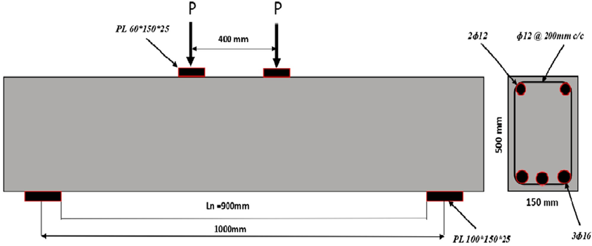
Specifics of tested reinforced CDBs with and without RPC.
2.1 Material specification
The material properties used in this study and the feasibility of making RPC blends are described here.
2.1.1 Cement
The local ordinary Portland cement type was used for casting the deep beam samples, in compliance with Iraqi Standard Specification I.Q.S. No. 5 (IQS 1984) [19].
2.1.2 Fine aggregate
Washed laboratory sand which is available locally in Najaf was used as the concrete mix components in this study. To obtain a very dense production of RPC mix, fine sand aggregate with a very fine gradation was used without particles of large sizes. Using a sieves with a maximum size of (450 micrometers) and a minimum size of (100 micrometers) (single classification) the fine aggregate was passed (Richard and Cheyrezy 1995) [20].
2.1.3 Silica fume
One of the characteristics of silica fume is that it mixes quickly and can be used in specific small proportions to improve the properties of concrete ACI 234 R (ACI 1996) [21]. Condensed silica fumes were used in this study (Sika® Fume S 92 D). According to the codes, the micro-silica used in this research is ASTM C1240 (ASTM 2015b) [22].
2.1.4 Superplasticizer
GLENIUM® 54 is a modern advanced material that is added to the concrete as a superplasticizer. These superplasticizers comply with standard specifications ASTM C494/C494M (ASTM 2015a) [23]. The superplasticizer is usually used in the concrete mix as a percentage of the weight of the cement where it has been used in a proportion of 2% of the weight of the cement as a water-reducing admixture. This modern material has many properties when used in the concrete mixture, including that it will significantly reduce the mixing water, increase the workability, obtain early and high-strength concrete with high porosity, thereby obtaining optimum density, improving water porosity, and obtaining a high-quality surface.
2.1.5 Steel fibers
Steel fibers are a substitute for coarse aggregate in the RPC mix. Steel fibers will be used in RPC to obtain reinforcing properties and improve ductility. The steel fiber has a length of almost 13 mm and a diameter of about 0.2 mm depending on ASTM A820/A820M (ASTM 2011) [24]. Steel fiber properties obtained from the manufacturer are shown in Table 1.
Properties of steel fibers*
| Property | Value |
|---|---|
| Length | 13 mm |
| Diameter | 0.2 mm |
| Density | 7,800 kg/m³ |
| Tensile strength | 2,600 MPa |
| Aspect ratio | 65 |
*Supplied by the manufacturer.
2.1.6 Steel reinforcing bars
The steel reinforcement used in the tensile and shear reinforcement zones in the deep reinforced concrete beams are according to the requirements (ASTM A615, 2001) [25].
A sample of Ukrainian reinforcing steel rods, used in tensile strength of Ø 16 mm and shear for the size of Ø 12 mm, were tested to determine their mechanical properties. The results are shown in Table 2.
Characteristics of steel reinforcement
| Property | Value Ø16 | Value Ø12 |
|---|---|---|
| Nominal diameter (mm) | 16 | 12 |
| Area (mm²) | 201 | 113 |
| Yield stress (MPa) | 580 | 338 |
| Ultimate strength (MPa) | 710 | 498 |
| Elongation at ultimate strength (%) | 13.25 | 14.35 |
3 Specimens preparation
In this study, plywood with a thickness of 20 mm was used to manufacture the sample mold and it was according to the required dimensions. Oil is used to coat the mold to ensure that the concrete does not stick, and the mold is removed easily. The rebar of the deep beams was lowered into these molds, and small concrete cubes measuring 2.5 cm were placed to achieve the required concrete cover. Mixing materials were weighed for normal concrete and RPC, according to the weight ratios of the required concrete mix. To mix the concrete components, a small mixer with a capacity of 0.25 cubic meters was used. Twelve cylinders (100 × 200) mm for each series were cast to specify the concrete properties. All things mentioned above are shown in Figure 2.
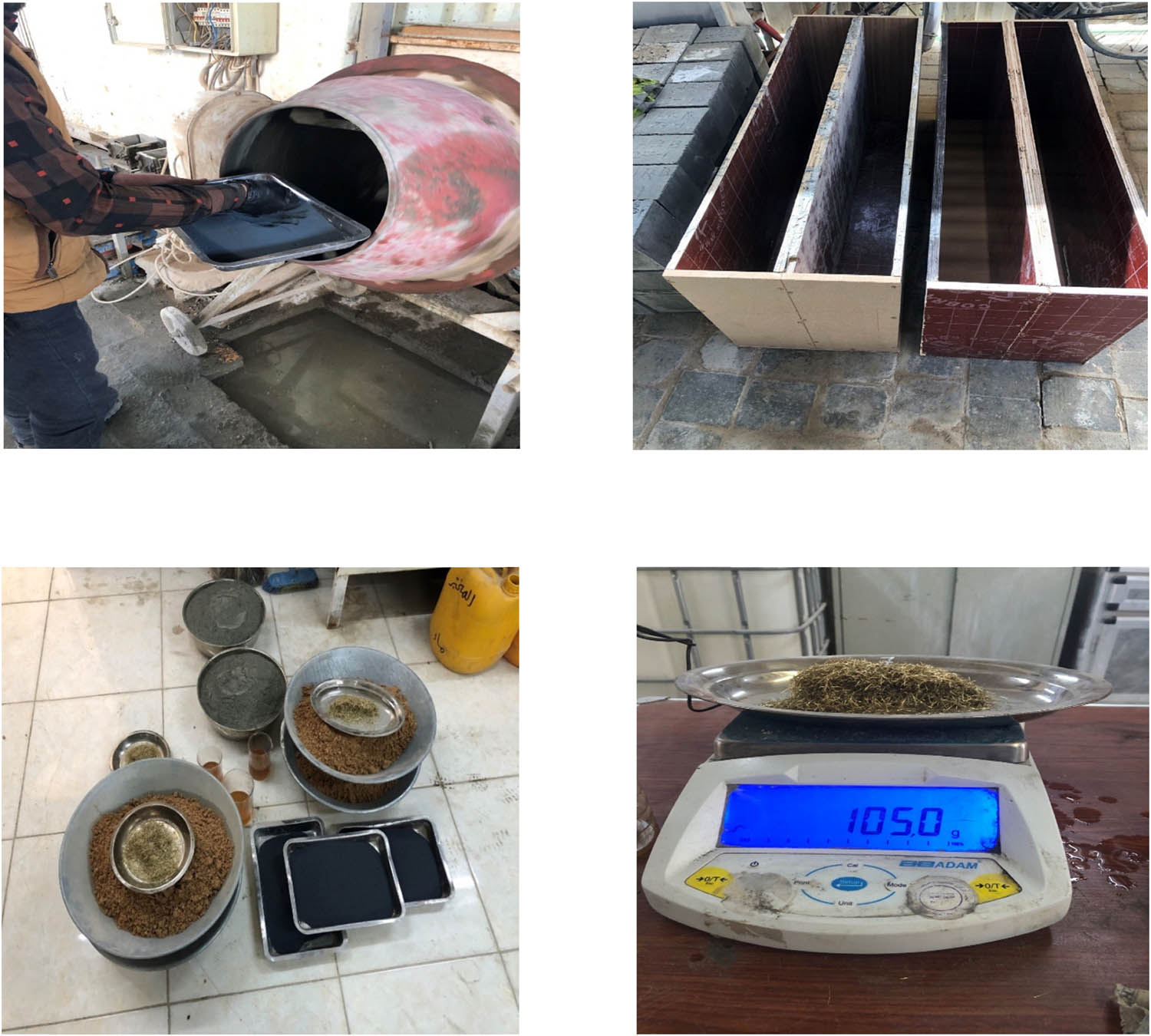
Specimens preparation and materials of RPC.
4 Concrete mix design
Before starting the concrete mix, a slump test was taken for the concrete mix, and it was the limits of the required specification as shown in Figure 3. Several experimental mixtures were used in this study before the mixture required for RPC was obtained. All deep beam samples as well as samples (cubes, cylinders, and drill cores) were 1∶1∶0.08 (cement:fine sand:silica fume) with a W/C of 0.25. The superplasticizer was used at the rate of 2% by weight of the cement, and for the steel fibers, the percentage of the weight was 0.7% in all mixtures. The values of the mechanical properties of specimens cast in the laboratory based on the codes to determine the required concrete properties (Table 3):
150 mm × 150 mm cubes based on ASTM C39 [26]. for compressive strength.
150 mm diameter × 150 mm long drilling core samples for getting real mechanical properties based on ASTM C42/C42M-18a [28]. such as (compressive strength, modulus of elasticity, Poison’s ratio, stress–strain curve, and longitudinal–lateral strain).
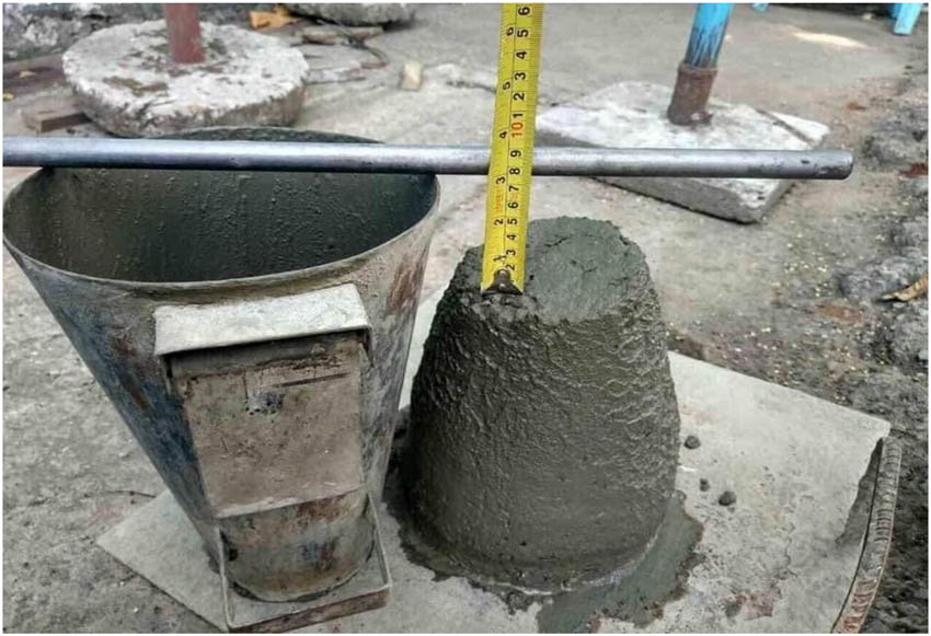
Slump test.
Mechanical properties of deep beam specimens
| Beam | *
|
*
|
*
|
*
|
*E c (Exp.) (GPa) | *E c equation (1) (GPa) | *E c equation (2) (GPa) | *ᶹ |
|---|---|---|---|---|---|---|---|---|
| *CDB | 32.7 | 38.7 | 25 | 2.20 | 23.5 | 26.8 | 25.88 | 0.2 |
| *RPCDB | 61.8 | 66.3 | 55.2 | 2.80 | 42.5 | — | — | 0.25 |
*CDB Control deep beam without RPC.
*RPCDB Reactive Powder Concrete deep beams.
*
*
*
*
*E c(exp.) modulus of elasticity of concrete based on (ASTM C469-02) [29] and is calculated from the stress–strain curve using slop = Rise/Run.
*E
c modulus of elasticity of ordinary concrete based on (ACI-318M-14) [30] and is computed using equation (1):
*E
c modulus of elasticity of ordinary concrete based on (ACI 363R-92) [31] and is computed using equation (2):
*ᶹ Poison’s ratio based on (ASTM C469-02) [29].
Note.
1. The values of
2. we can note that the above two equations are for calculating E c for normal concrete only, and there is no equation for calculating E c for RPC until now.
3. We can observe that the value of the drilling core compressive (
5 Testing procedure
After the completion of the curing process of the deep beams at the age of 28 days, they were removed from the water. To find out the crack propagation behavior, the specimens of deep beams were cleaned, white-painted, and marked. Using a jack hydraulic machine with two points load as shown in Figure 4, all deep beams were tested to study their behavior. To note the development of cracks, strains, and deflections of the beam, the test machine was stopped at every 10 kN. The deflection dial gauge was placed in the middle of the deep beam between the two points of the applied load and in contact with the lower face. When the cracks began to develop with the gradual increase in the load, the maximum failure load and load removal were recorded to take pictures of the final crack pattern. In addition, after the failure, six core drill specimens were taken from the undamaged regions (areas without cracks) of deep beams’ body as shown in Figure 5. The specimens taken from the deep beam body with normal concrete and deep beam with RPC have been divided into three specimens each. The specimens were subjected to testing using the compression strength machine. In conjunction with testing specimens under the compression machine, a digital caliper and mini digital thickness gauge were used, which have been manufactured manually to get the real mechanical properties, especially the stress–strain curve as shown in Figure 6.
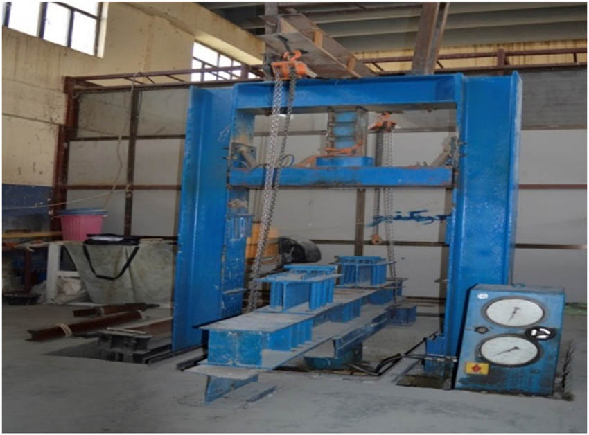
Universal testing machine.
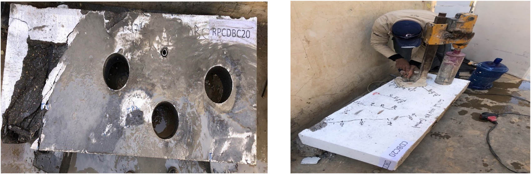
Taking drilling core samples.
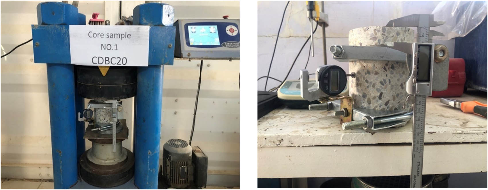
Testing compression machine with two gauges to calculate the strains.
6 Results and discussion
The experimental results obtained are summarized in Table 4, including the first cracking load, final load, final shear strength, failure mode, and crack patterns. Moreover, load-deflection, shear crack width, and stress–strain curves of these beams are analyzed and studied. They are illustrated in Figures 7–11. The CDB (reference specimen) failed in shear. It was noticed that in the middle of the deep beam region, the appearance of the first flexural crack for the load period of 80 kN, and when the load was increased to a load of 140 kN, we noticed the appearance of another crack. With the increase in the load, more propagation of flexural cracks was observed but they stopped at 240 kN load. On the other hand, when loading 160 kN, it was noticed that the first shear crack appeared, which extended from the inner edge of the support toward the point load. When the load was increased little by little until it reached 200 kN, another primary shear crack appeared in the middle of the support base. It was also observed that the type of bending crack and shear spread on increasing the load. Upon failure at full load, the main shear crack occurred at an angle of 58° as shown in Figure 7. The failure occurred in the control deep beam CDB when the load reached 440 kN or the shear load reached 220 kN. Through the results, it was observed that the beam suddenly failed, and the failure mode was the shear-compression failure type. The specimen RPCDB (with RPC) failed in shear. The appearance of the first bending crack was observed in the center of the sample when the load reading was about 80 kN. Other small cracks appeared widely between the two supports starting from the bottom toward the load points when the load gradually started to increase. Other diagonal shear cracks formed (in the left as well as the right shear span of the beam) were observed first at different points at a load of 260 kN and then started to extend towards the loading points. With the increase in the load, these cracks rapidly spread and widened. The type of failure that occurred in the beam was shear failure type and its location was at the edge of the beam, at the support, and was crushing and dislodging part of the deep beam extending from the support towards the loading point as shown in Figure 8. Through the readings, we note that the failure of the RPCDB sample was at a load of 740 kN or a shear load of 370 kN. Through the results, it was observed that the beam suddenly failed, and the failure mode was the shear-compression failure type. Also, from the significant decrease in shear strength of the reference beam, when compared CDB to the RPCDB, the presence of reactive concrete powder reduces the shear capacity. In addition, the sample RPCDB had decreased shear strength by 68% compared to the shear strength of the CDB reference beam. The behavior of the cracks was represented by the emergence and extension from the support point to the load point, at an angle of approximately 58°, and distributed on both types of deep beams.
Mechanical properties of deep beam specimens
| Specimen | First shear crack strength (kN) | Ultimate strength (kN) | Shear force (kN) | Increase in the first shear crack capacity (%) | Increase in ultimate capacity (%) | Modes of failure |
|---|---|---|---|---|---|---|
| CDB | 160 | 440 | 220 | 0 (reference) | 0 (reference) | Shear – Compression |
| RPCDB | 260 | 740 | 370 | 62.5 | 68 | Shear – Compression |
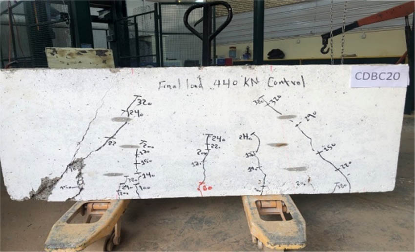
Failure mode and crack pattern for CDB.
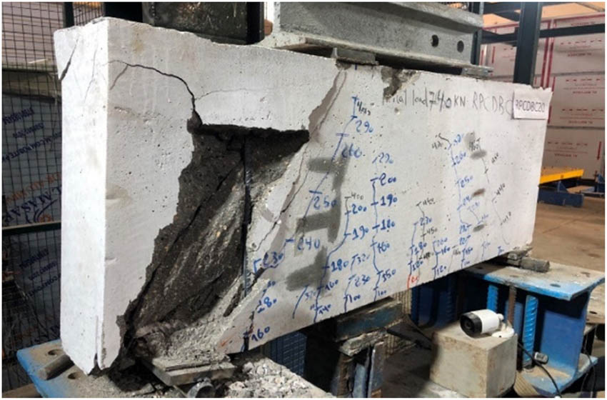
Failure mode and crack pattern for RPCDB.
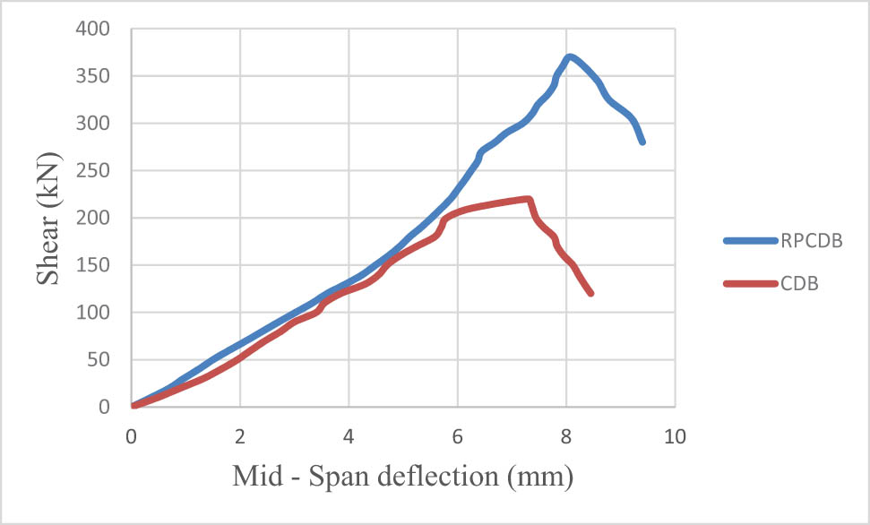
Deflection profile for beams in CDB and RPCDB.
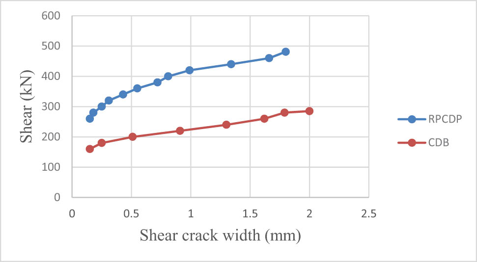
Crack width profile for beams in CDB and RPCDB.
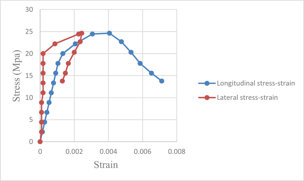
Stress–strain curve for beam CDB.
Figure 9 shows the deflection behavior of CDB and RPCDB deep beams. Deflection readings were recorded at each overload until sample failure. Depending on the deflection instrument, a deflection value of 8.05 mm was read for the RPCDB beam at the highest peak but only a value of 7.29 mm for the CDB beam was recorded. However, after maximum load, the behavior of the highest peak in the graph for RPCDB and CDB beams showed similar patterns, represented by a decrease in load but the deflection will start to gradually increase. The RPCDB beam had a more gradual post-peak increase in deflection compared to CDB. Before complete failure, the RPCDB beam was followed up with a maximum deflection reading of 9.40 mm while a reading of 8.45 mm was recorded for CDB.
Using a special microscope, the readings of the shear crack width of the deep beams were recorded during the loading stages. For the reference beam CDB, the first shear crack was observed at 160 kN, and the crack width was read with a value of 0.15 mm. Upon reaching 65% of the final shear load (285 kN), it was observed that the crack width continued to expand with each load and the crack diagonal increased to 2 mm. On the other hand, at a load of 260 kN, the occurrence of the first shear crack of the RPCDB beam was confirmed, and a crack width reading of 0.15 mm was recorded with increasing loading, and a shear diagonal crack reading of 1.8 mm was recorded at the load of 480 kN. Figure 10 shows the evolution of shear crack widths for the CDB and RPCDB loading samples. From observation, the beam (RPCDB) delayed the appearance of the first shear crack by (78%) with respect to the load compared with the beam (CDB) due to the higher shear capacity of specimen RPCDB. Moreover, the beam (RPCDB) reduced the first shear crack width by (11%) compared with the beam (CDB) at (65%) of the ultimate shear load.
From the drilled core test based on ASTM C42/C42M-18a [19] applied on beams RPCDB and CDB, real and realistic data for those deep beams were obtained, which were translated in the form of stress–strain curves which include longitudinal and lateral stress–strain curves for concrete compression zone of beams CDB and RPCDB, as shown in Figures 11 and 12. A longitudinal stress–strain curve of the concrete compressive zone of CDB and RPCDB samples was combined with one aggregation curve to compare the results between these two samples as shown in Figure 13. In Figure 13, the stress–strain curve of the CDB reference sample is shown, which shows the drop at the loading end. However, the behavior of the RPCDB sample is very different compared to that of the CDB sample of the higher stress and decreased strain of the RPCDB and this is evident by the high peak and little extension of the curve. The Young’s modulus increased from 27,932 MPa for reference mixings to 43,029 MPa for mixings that have 10% silica fume powder. In addition, the flexural strength rises by rising silica fume content to 12.5%, after which the value decreases [32].
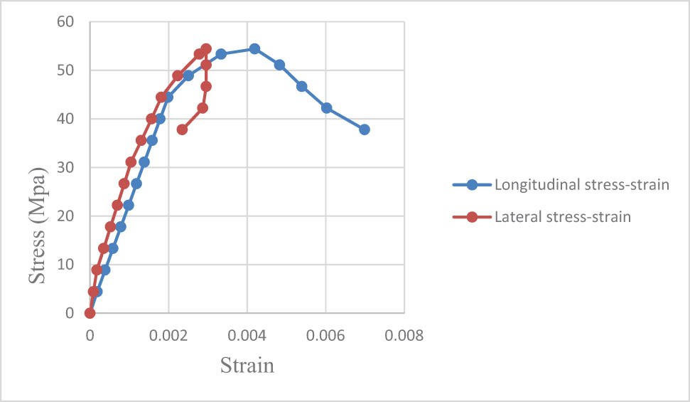
Stress–strain curve for beam RPCDB.
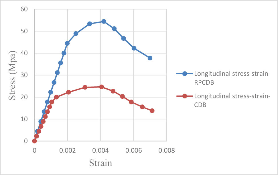
Stress–strain curve for beam RPCDB and CDB.
From the split-cylinder test based on ASTM C496 [18], the stress-strain results were obtained for the concrete tensile zone for CDB and RPCDB samples as shown in Figure 14.
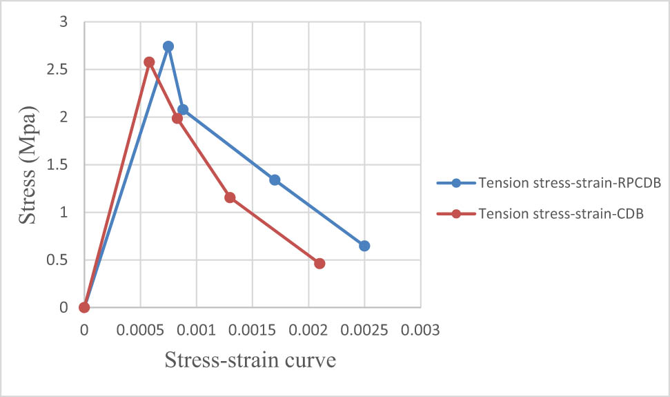
Stress–strain curve for tension zone in beams RPCDB and CDB.
In Figure 14, for the stress–strain curves for the stress in the tension zone for CDB and RPCDB samples, it can be observed that the tension stress of beam RPCDB is higher than beam CDB. Moreover, the strain of the sample beam RPCDB is higher than that of the sample CDB. The increase in tensile stress for the RPCDB sample at maximum stress compared with the CDB sample is 10%, while the increase in tensile strain for the RPCDB sample at maximum stress is 29%.
All the results of stress-strain for samples RPCDB and CDB were compared based on the results of previous studies as shown in Figure 15 and it showed an acceptable agreement with those results, which proves the validity of these laboratory results.
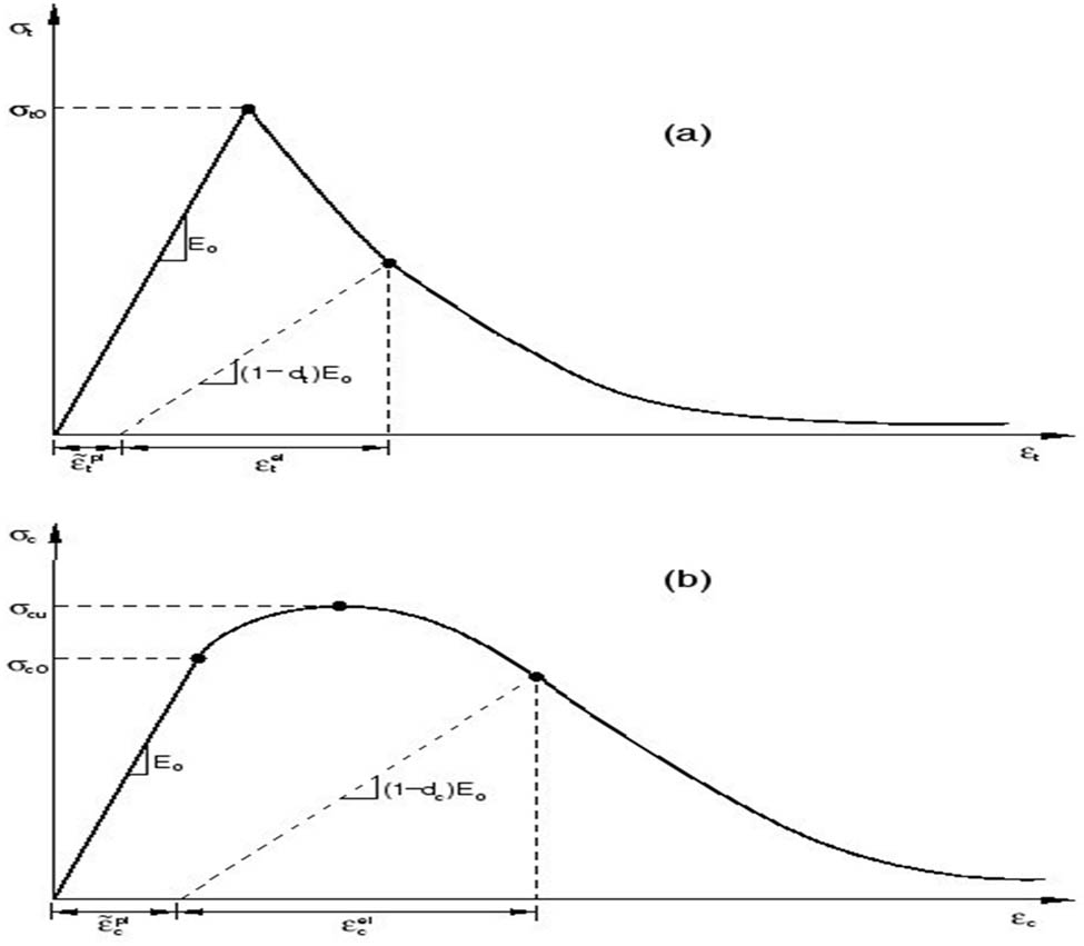
Stress-strain for (a) tension and (b) compression zone in concrete.
7 Conclusion
The presence of the RPC caused an exponential increase in the final strength of the RPCDB sample. The maximum strength of the RPCDB sample in this research increased by about 68% from the final strength of the CDB.
The presence of RPC caused an exponential increase in the first shear crack capacity of the deep beams. The RPCDB sample increased by approximately 62.5% of the maximum capacity of the CDB.
Through this study, we can observe that the value of the drilling core compressive (
The resistance of the RPCDB sample increased at all stages of loading and thus led to an increase in the deflection at the corresponding loads. The maximum deflection overload of the RPCDB was increased by about 10–11% compared with CDB specimen.
From this study, the beam (RPCDB) delayed the appearance of the first shear crack by 78% with respect to the load compared with the beam (CDB) due to the higher shear capacity of specimen RPCDB. Moreover, the beam (RPCDB) reduced the first shear crack width by 11% compared with the beam (CDB) at 65% of the ultimate shear load.
From the drilled core test based on ASTM C42/C42M-18a [28] applied on beams RPCDB and CDB real has observed that the stress results of RPCDB have increased by 118% at the maximum stress compared with CDB. In contrast, the strain scores for CDB increased by 22.5% at maximum stress compared to RPCDB.
From the stress-strain results of split-cylinder test based on ASTM C496 [27], the increase in tensile stress for the RPCDB sample at maximum stress compared with the CDB sample is 10%, while the increase in tensile strain for the RPCDB sample at maximum stress is 29%.
Acknowledgements
The authors wish to extend their thanks to the Fourth Dimension Contracting Company for their support and guidance and expertise that greatly assisted the research, especially in preparing the research materials and laboratory.
-
Conflict of interest: The authors declare that they have no conflict of interest.
-
Data availability statement: Most datasets generated and analyzed in this study are comprised in this submitted manuscript. The other datasets are available on reasonable request from the corresponding author with the attached information.
References
[1] Chadli M, Mekki M, Mezghiche B. Formulation and study of metal fiber-reinforced reactive powder concrete. World J Eng. 2018;15(4):531–9.10.1108/WJE-04-2017-0094Suche in Google Scholar
[2] Bae BI, Lee MS, Choi CS, Jung HS, Choi HK. Evaluation of the ultimate strength of the ultra-high-performance fiber-reinforced concrete beams. Appl Sci. 2021;11(7):2951.10.3390/app11072951Suche in Google Scholar
[3] Albidah A, Abadel A, Abbas H, Almusallam T, Al-Salloum Y. Experimental and analytical study of strengthening schemes for shear deficient RC deep beams. Constr Build Mater. 2019;216:673–86.10.1016/j.conbuildmat.2019.05.024Suche in Google Scholar
[4] Zhang JH, Li SS, Xie W, Guo YD. Experimental study on shear capacity of high strength reinforcement concrete deep beams with small shear span–depth ratio. Materials. 2020;13(5):1218.10.3390/ma13051218Suche in Google Scholar PubMed PubMed Central
[5] Rahim NI, Mohammed BS, Al-Fakih A, Wahab MMA, Liew MS, Anwar A, et al. Strengthening the structural behavior of web openings in RC deep beam using CFRP. Materials. 2020;13(12):2804.10.3390/ma13122804Suche in Google Scholar PubMed PubMed Central
[6] Abadel AA, Albidah AS. Investigation of shear reinforcement schemes for RC deep beams. Arab J Sci Eng. 2021;46:4747–63.10.1007/s13369-020-05123-zSuche in Google Scholar
[7] Lee N, Chisholm D. Reactive Powder Concrete, Study Report SR 146. Ltd, Judgeford, New Zealand, 2005.Suche in Google Scholar
[8] Huynh L, Foster S, Valipour H, Randall R. High strength and reactive powder concrete columns subjected to impact: Experimental investigation. Constr Build Mater. 2015;78:153–71.10.1016/j.conbuildmat.2015.01.026Suche in Google Scholar
[9] Liu S, Xie G, Rao M. Effect of waste glass powder on properties and microstructure of ultrahigh performance cement based materials. Mater Res Innov. 2013;17(sup1):210–4.10.1179/1432891713Z.000000000217Suche in Google Scholar
[10] Richard P. A new ultra-high strength cementitious material. In Proc. 4th Intl. Symp. on Utilization of High Strength/High Performance Cencrete; 1996. p. 1343–9.Suche in Google Scholar
[11] Matte V, Moranville M. Durability of reactive powder composites: influence of silica fume on the leaching properties of very low water/binder pastes. Cem Concr Compos. 1999;21(1):1–9.10.1016/S0958-9465(98)00025-0Suche in Google Scholar
[12] Yu R, Spiesz P, Brouwers HJH. Mix design and properties assessment of ultra-high performance fibre reinforced concrete (UHPFRC). Cem Concr Res. 2014;56:29–39.10.1016/j.cemconres.2013.11.002Suche in Google Scholar
[13] Gao R, Stroeven P, Hendriks CF. Mechanical properties of reactive powder concrete beams. Spec Publ. 2005;228:1237–52.Suche in Google Scholar
[14] Warnock R. Short-term and time-dependent flexural behavior of steel-fiber reinforced reactive powder concrete beams. Experimental and theoretical study. University of New South Wales; 2005.Suche in Google Scholar
[15] Yujing L, Wenhua Z, Fan W, Peipei W, Weizhao Z, Fenghao Y. Static mechanical properties and mechanism of C200 ultra-high performance concrete (UHPC) containing coarse aggregates. Sci Eng Composite Mater. 2020;27(1):186–95. 10.1515/secm-2020-0018.Suche in Google Scholar
[16] Li H, Wu F, Bu L, Liu Y, Yao J. Study on the compression performance of steel reactive powder concrete columns. Adv Struct Eng. 2020;23(10):2018–29.10.1177/1369433220903986Suche in Google Scholar
[17] Geng X, Zhou W, Yan J. Reinforcement of orthogonal ties in steel-fiber-reinforced reactive powder concrete anchorage zone. Adv Struct Eng. 2019;22(10):2311–21.10.1177/1369433219838085Suche in Google Scholar
[18] Du G, Zhang X, Bu L, Hou Q. Axial compression capacity analysis of prefabricated steel reactive powder concrete columns in prefabricated modular buildings. Adv Struct Eng. 2022;25(5):1072–90.10.1177/13694332211063673Suche in Google Scholar
[19] IQS (Iraqi Specifications of Central Agency for Standardization and Quality Control of Planning Council). Standard specification for portland cement. IQS 5-1984. Baghdad, Iraq: IQS; 1984.Suche in Google Scholar
[20] Richard P, Cheyrezy M. Composition of reactive powder concretes. Cem Concr Res. 1995;25(7):1501–11.10.1016/0008-8846(95)00144-2Suche in Google Scholar
[21] Aldred JM, Holland TC, Morgan DR, Roy DM, Bury MA, Hooton RD, et al. Guide for the use of silica fume in concrete. ACI–American Concrete Institute–Committee: Farmington Hills, MI, USA, 234; 2006.Suche in Google Scholar
[22] ASTM. Standard specification for silica fume used in cementitious mixtures. ASTM C1240. West Conshohocken, PA: ASTM; 2015b.Suche in Google Scholar
[23] ASTM. Standard specification for chemical admixtures for concrete. ASTM C494/C494M. West Conshohocken, PA: ASTM; 2015a.Suche in Google Scholar
[24] ASTM. Standard specification for steel fibers for fiber-reinforced concrete. ASTM A820/A820M. West Conshohocken, PA: ASTM; 2011.Suche in Google Scholar
[25] ASTM Designation A615/A615M-01b. Standard Specifications for Deformed and Plain Billet-Steel Bars for Concrete Reinforcement, Annual Book of ASTM Standards. American Society for Testing and Materials, Philadelphia, Pennsylvania, vol. 1.04; 2001.Suche in Google Scholar
[26] ASTM. Standard Test Method for Compressive Strength of Cylindrical Concrete Specimens. ASTM C39/C39M-18. West Conshohocken, PA: ASTM; 2018.Suche in Google Scholar
[27] ASTM. Standard Test Method for Splitting Tensile Strength of Cylindrical Concrete Specimens. ASTM C496-96. West Conshohocken, PA: ASTM; 2017.Suche in Google Scholar
[28] ASTM. Standard Test Method for Obtaining and Testing Drilled Cores and Sawed Beams of Concrete. ASTM C42/C42M-18a. West Conshohocken, PA: ASTM; 2018.Suche in Google Scholar
[29] ASTM. Standard Test Method for Static Modulus of Elasticity and Poisson’s Ratio of Concrete in Compression. ASTM C469-02. West Conshohocken, PA: ASTM; 2002.Suche in Google Scholar
[30] ACI Committee 318. Building Code Requirements for Structural Concrete and Commentary. Reported by ACI Committee 318M, 2014; 2014.Suche in Google Scholar
[31] ACI Committee-363. State of the Art Report on High Strength Concrete (ACI 363R-92). American Concrete Institute, Detroit; 1997.Suche in Google Scholar
[32] Mezher TM, Breesem KM, Hassen DR, Jaafar AA. Stress-strain behavior and flexural strength of silica fume polymer-modified concrete. In IOP Conference Series: Materials Science and Engineering. Vol. 881, No. 1. IOP Publishing; 2020, July. p. 012167.10.1088/1757-899X/881/1/012167Suche in Google Scholar
© 2023 the author(s), published by De Gruyter
This work is licensed under the Creative Commons Attribution 4.0 International License.
Artikel in diesem Heft
- Regular Articles
- Design optimization of a 4-bar exoskeleton with natural trajectories using unique gait-based synthesis approach
- Technical review of supervised machine learning studies and potential implementation to identify herbal plant dataset
- Effect of ECAP die angle and route type on the experimental evolution, crystallographic texture, and mechanical properties of pure magnesium
- Design and characteristics of two-dimensional piezoelectric nanogenerators
- Hybrid and cognitive digital twins for the process industry
- Discharge predicted in compound channels using adaptive neuro-fuzzy inference system (ANFIS)
- Human factors in aviation: Fatigue management in ramp workers
- LLDPE matrix with LDPE and UV stabilizer additive to evaluate the interface adhesion impact on the thermal and mechanical degradation
- Dislocated time sequences – deep neural network for broken bearing diagnosis
- Estimation method of corrosion current density of RC elements
- A computational iterative design method for bend-twist deformation in composite ship propeller blades for thrusters
- Compressive forces influence on the vibrations of double beams
- Research on dynamical properties of a three-wheeled electric vehicle from the point of view of driving safety
- Risk management based on the best value approach and its application in conditions of the Czech Republic
- Effect of openings on simply supported reinforced concrete skew slabs using finite element method
- Experimental and simulation study on a rooftop vertical-axis wind turbine
- Rehabilitation of overload-damaged reinforced concrete columns using ultra-high-performance fiber-reinforced concrete
- Performance of a horizontal well in a bounded anisotropic reservoir: Part II: Performance analysis of well length and reservoir geometry
- Effect of chloride concentration on the corrosion resistance of pure Zn metal in a 0.0626 M H2SO4 solution
- Numerical and experimental analysis of the heat transfer process in a railway disc brake tested on a dynamometer stand
- Design parameters and mechanical efficiency of jet wind turbine under high wind speed conditions
- Architectural modeling of data warehouse and analytic business intelligence for Bedstead manufacturers
- Influence of nano chromium addition on the corrosion and erosion–corrosion behavior of cupronickel 70/30 alloy in seawater
- Evaluating hydraulic parameters in clays based on in situ tests
- Optimization of railway entry and exit transition curves
- Daily load curve prediction for Jordan based on statistical techniques
- Review Articles
- A review of rutting in asphalt concrete pavement
- Powered education based on Metaverse: Pre- and post-COVID comprehensive review
- A review of safety test methods for new car assessment program in Southeast Asian countries
- Communication
- StarCrete: A starch-based biocomposite for off-world construction
- Special Issue: Transport 2022 - Part I
- Analysis and assessment of the human factor as a cause of occurrence of selected railway accidents and incidents
- Testing the way of driving a vehicle in real road conditions
- Research of dynamic phenomena in a model engine stand
- Testing the relationship between the technical condition of motorcycle shock absorbers determined on the diagnostic line and their characteristics
- Retrospective analysis of the data concerning inspections of vehicles with adaptive devices
- Analysis of the operating parameters of electric, hybrid, and conventional vehicles on different types of roads
- Special Issue: 49th KKBN - Part II
- Influence of a thin dielectric layer on resonance frequencies of square SRR metasurface operating in THz band
- Influence of the presence of a nitrided layer on changes in the ultrasonic wave parameters
- Special Issue: ICRTEEC - 2021 - Part III
- Reverse droop control strategy with virtual resistance for low-voltage microgrid with multiple distributed generation sources
- Special Issue: AESMT-2 - Part II
- Waste ceramic as partial replacement for sand in integral waterproof concrete: The durability against sulfate attack of certain properties
- Assessment of Manning coefficient for Dujila Canal, Wasit/-Iraq
- Special Issue: AESMT-3 - Part I
- Modulation and performance of synchronous demodulation for speech signal detection and dialect intelligibility
- Seismic evaluation cylindrical concrete shells
- Investigating the role of different stabilizers of PVCs by using a torque rheometer
- Investigation of high-turbidity tap water problem in Najaf governorate/middle of Iraq
- Experimental and numerical evaluation of tire rubber powder effectiveness for reducing seepage rate in earth dams
- Enhancement of air conditioning system using direct evaporative cooling: Experimental and theoretical investigation
- Assessment for behavior of axially loaded reinforced concrete columns strengthened by different patterns of steel-framed jacket
- Novel graph for an appropriate cross section and length for cantilever RC beams
- Discharge coefficient and energy dissipation on stepped weir
- Numerical study of the fluid flow and heat transfer in a finned heat sink using Ansys Icepak
- Integration of numerical models to simulate 2D hydrodynamic/water quality model of contaminant concentration in Shatt Al-Arab River with WRDB calibration tools
- Study of the behavior of reactive powder concrete RC deep beams by strengthening shear using near-surface mounted CFRP bars
- The nonlinear analysis of reactive powder concrete effectiveness in shear for reinforced concrete deep beams
- Activated carbon from sugarcane as an efficient adsorbent for phenol from petroleum refinery wastewater: Equilibrium, kinetic, and thermodynamic study
- Structural behavior of concrete filled double-skin PVC tubular columns confined by plain PVC sockets
- Probabilistic derivation of droplet velocity using quadrature method of moments
- A study of characteristics of man-made lightweight aggregate and lightweight concrete made from expanded polystyrene (eps) and cement mortar
- Effect of waste materials on soil properties
- Experimental investigation of electrode wear assessment in the EDM process using image processing technique
- Punching shear of reinforced concrete slabs bonded with reactive powder after exposure to fire
- Deep learning model for intrusion detection system utilizing convolution neural network
- Improvement of CBR of gypsum subgrade soil by cement kiln dust and granulated blast-furnace slag
- Investigation of effect lengths and angles of the control devices below the hydraulic structure
- Finite element analysis for built-up steel beam with extended plate connected by bolts
- Finite element analysis and retrofit of the existing reinforced concrete columns in Iraqi schools by using CFRP as confining technique
- Performing laboratory study of the behavior of reactive powder concrete on the shear of RC deep beams by the drilling core test
- Special Issue: AESMT-4 - Part I
- Depletion zones of groundwater resources in the Southwest Desert of Iraq
- A case study of T-beams with hybrid section shear characteristics of reactive powder concrete
- Feasibility studies and their effects on the success or failure of investment projects. “Najaf governorate as a model”
- Optimizing and coordinating the location of raw material suitable for cement manufacturing in Wasit Governorate, Iraq
- Effect of the 40-PPI copper foam layer height on the solar cooker performance
- Identification and investigation of corrosion behavior of electroless composite coating on steel substrate
- Improvement in the California bearing ratio of subbase soil by recycled asphalt pavement and cement
- Some properties of thermal insulating cement mortar using Ponza aggregate
- Assessment of the impacts of land use/land cover change on water resources in the Diyala River, Iraq
- Effect of varied waste concrete ratios on the mechanical properties of polymer concrete
- Effect of adverse slope on performance of USBR II stilling basin
- Shear capacity of reinforced concrete beams with recycled steel fibers
- Extracting oil from oil shale using internal distillation (in situ retorting)
- Influence of recycling waste hardened mortar and ceramic rubbish on the properties of flowable fill material
- Rehabilitation of reinforced concrete deep beams by near-surface-mounted steel reinforcement
- Impact of waste materials (glass powder and silica fume) on features of high-strength concrete
- Studying pandemic effects and mitigation measures on management of construction projects: Najaf City as a case study
- Design and implementation of a frequency reconfigurable antenna using PIN switch for sub-6 GHz applications
- Average monthly recharge, surface runoff, and actual evapotranspiration estimation using WetSpass-M model in Low Folded Zone, Iraq
- Simple function to find base pressure under triangular and trapezoidal footing with two eccentric loads
- Assessment of ALINEA method performance at different loop detector locations using field data and micro-simulation modeling via AIMSUN
- Special Issue: AESMT-5 - Part I
- Experimental and theoretical investigation of the structural behavior of reinforced glulam wooden members by NSM steel bars and shear reinforcement CFRP sheet
- Improving the fatigue life of composite by using multiwall carbon nanotubes
- A comparative study to solve fractional initial value problems in discrete domain
- Assessing strength properties of stabilized soils using dynamic cone penetrometer test
- Investigating traffic characteristics for merging sections in Iraq
- Enhancement of flexural behavior of hybrid flat slab by using SIFCON
- The main impacts of a managed aquifer recharge using AHP-weighted overlay analysis based on GIS in the eastern Wasit province, Iraq