A computational iterative design method for bend-twist deformation in composite ship propeller blades for thrusters
-
Sondre Ø. Rokvam
 ,
Nils Petter Vedvik
,
Nils Petter Vedvik

Abstract
This study investigates the feasibility of utilising common composite material layup techniques in ship propeller blade design to achieve an automatic pitch adjustment through bending-induced twist deformation. A comprehensive design approach, including various reinforcement materials and arrangements, was employed to attain the desired foil pitching, while minimising other undesirable deformation modes. The design process involved iterative computational analysis using finite element analysis and a deformation mode analysis based on foil shape parameters. The research showed that the proposed design approach effectively found options to improve the desired foil parameter pitch, while minimising undesirable deformation modes such as blade deflection and foil shape change. Furthermore, the proposed blade design was tested in thruster steering operational conditions and was found to have a pitch change well matched, potentially countering some changes in fluid flow. When compared to Kumar and Wurm’s design, which only focused on the angular orientation of glass reinforcement, the proposed design was found to outperform the twisting by achieving the same twist for a blade half the length. This study provides valuable insights into the utilisation of composite materials in ship propeller design and highlights the potential for further improvement through a composite engineering design approach.
1 Introduction
Having reliable and efficient propeller systems is vital for keeping ships operational, reducing the energy needed to manoeuvre a ship, and reducing operating costs and the environmental footprint. Today, solid, rigid propellers in metal are the norm on large ships. They usually show negligible deformations when loaded and are generally assumed to behave as rigid components during operations. Consequently, the geometric shape of the propeller is the main factor when designing metal propellers for hydrodynamic performance [1].
An alternative approach to propeller design is flexible self-pitching or passive adaptive propeller blades that automatically adjust to a more optimal shape under certain operating conditions. The adjustment of the propeller blade functions similar to twisting the blade pitch like in traditional controllable pitch propellers, which have high efficiency in a broader range of ship speeds and loading conditions compared to fixed pitch propellers [2]. As the pitch change in passive adaptive blades is an instantaneous material response to the operational loads, no active control is required.
A bending-induced twist deformation (commonly called bend-twist coupled deformation) is the desired deformation response in a passive adaptive pitching propeller blade [3,4,5,6,7,8,9,10]. Researchers have previously designed bend-twist deformation into foil structures using fibre-reinforced plastic (FRP) composite materials to function as an immediate pitch adjustment that mitigates periodic load variations [4,5,6,8,9,10,11,12,13,14,15,16,17,18,19]. It is the anisotropic nature of FRP that allows for designing a bending-induced twist deformation through FRP laminate layup orientation and tailoring, sometimes with computational optimisation [3,7,9,10].
In composite prototyping, composite tailoring for fluid elastic propellers has been around in literature since at least the 1970s, but earlier published (or even unpublished) prototypes might exist [16,20]. The marine composite propeller field rejuvenated composite propellers with 1-way, and later 2-way, fluid–structure interaction (FSI) modelling during the period 1990–2000 [9,10,21]. Optimisation of layup’s ply orientation for composite propeller was shown around the same time [7]. However, while being a remarkable feat, optimisation can only be done within the considered parameters, and how one can arrange various reinforcements to make a composite propeller is mainly limited by the materials, blade geometry, imagination, and manufacturability. In recent years, publications on tidal turbines, wind turbines, and marine propellers with bend-twist have been numerous towards composite blade shapes and material layups for improved performance [2,3,4,5,6,8,12,15,18,19,22,23,24,25,26,27,28,29,30,31,32,33,34]. Works on experimental verification of 2-way FSI analyses are also being published, rooting these publications in reality [12,35,36].
Several of the research teams that worked on FRP marine propeller blade designs with bend-twist deformation approached with high competence within modelling fluid mechanics. The two most common FRP materials, glass and carbon fibre, have been used for composite material layup designs, separately but also together in hybrid composite designs [17,37]. However, when it comes to the structural build-up of the propeller, this has mostly limited the composite material design for bend-twist in propeller blade designs to laminate coupling from ply orientation in the foil skins. In other flexing foil designs, like wind turbine blade wings, it is common to use a substructure system of stiffeners, ribs, and spars to reinforce and guide or limit deformation.
Simultaneously, most publications on marine propellers focus on propeller designs with different diameters, geometries with large skew, various blades, and different expected blade loads during operation, making it challenging to extract universal design rules for composite prototyping. As this work aims to approach propeller design from a composite engineering perspective, evaluating propeller performance with 2-way FSI was out of scope. Instead, this study applied loading by pressure distributions from a one-way FSI analysis and focused on how different build-up materials and the composition of these to construct the blade influenced the characteristics of the blade deformation under these loads. While blade performance might be the ultimate goal, several other factors are essential for the design performance. Some of these are the blade’s fluid-dynamic geometry, the material’s properties and arrangement composition, and how the blade’s fluid-dynamic geometry changes under load. This geometry change, i.e. deformation, is focused on in this study. The assumption is that finding a design that shows an elastic response with a significant initial bend-twist might be a good design in general.
The assumption is supported by investigations and simulations showing that the difference in blade deflection deformation between a 1-way FSI analysis and a 2-way FSI analysis with a steady state is often less than 20% but could presumably be more significant if a better bend-twist property is designed [3,12,36].
This study explores what bend-twist deformation properties can be achieved in a relatively small ship propeller blade (as it goes on a thruster) using strategically placed stiffeners or patches and a glass and carbon hybrid composite layup tailoring. The study is applied in an engineering challenge with azimuth thrusters to solve a specific engineering task: Dimension the twisting in a bend-twist propeller blade to counter the inflow change at blade radius 0.9 when the thruster is turned for steering from a cruising scenario. The dimensioned pitch change cause the load variation to mitigate and might cause the noise profile from the propeller to be reduced [38].
The focus of this study is to explore how bend-twisting deformation can be introduced into blades using the unique characteristics of composite materials. The study is limited to investigating the response of the blades to the initial load case. Effects due to FSIs will need to be added when designing a realistic commercial propeller blade. However, the methods described here, how to best arrange the composite material to trigger bend-twisting effect, will remain the same. The approach to the design process applied in the study is illustrated in Figure 1.
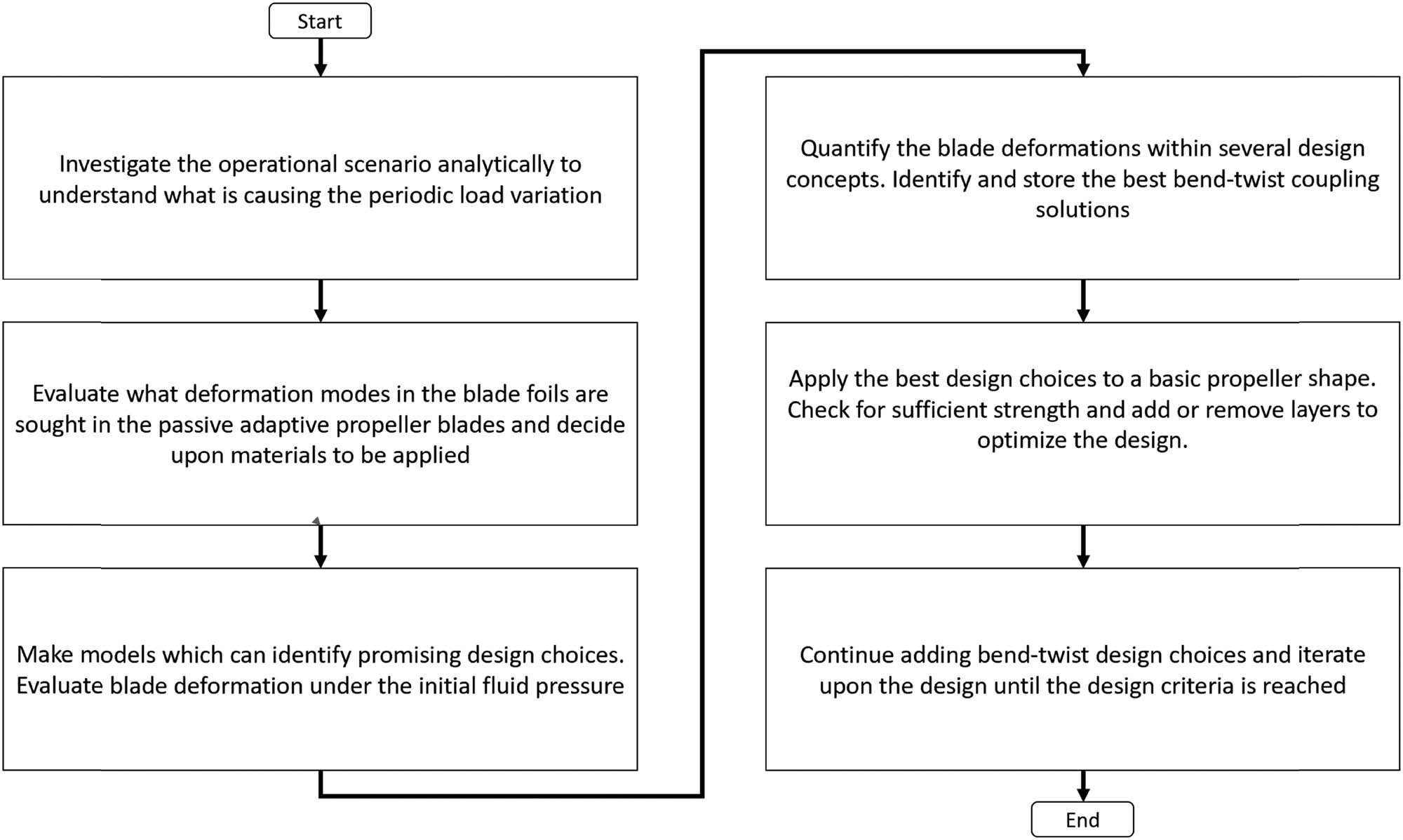
A flowchart illustrating the approach for making bend-twist propeller blades from a mechanical engineering point of view, focusing on which design choices contribute to desirable elastic response in the blades.
2 Background
Carlton states that the propulsion efficiency of a propeller is related to the angle of attack (α) of the foils in the propeller blades [11], propeller blade foils and α are shown in Figure 2. α is defined as the difference between the pitch angle of the foil (θ) and the apparent angle of the fluid flow (ϕ), as shown in Figure 2 and equation (1).
The propeller blade foils have an optimum α, where the reaction force provides the best possible contribution to the vessel’s propulsion. θ is the angle between the plane of rotation and the chord line in the propeller blade foil profile. ϕ is based on operation conditions and is determined as the angle between the vector Va, a combination of relative inflow velocity, U ∞, and the rotational velocity, r ω, also shown in Figure 2.

Illustration showing a propeller system and propeller blade foils. α is the difference between θ and φ. The foil chord line is used to measure θ. The mean camber line, the mid-line between the two propeller surfaces, is used to describe the shape of the foil and to monitor the foil profile’s shape.
Propellers operating in asymmetric flow conditions commonly cause local variations in ϕ and α on the different propeller blades. For example, when a propeller blade revolves in an asymmetric flow, ϕ and α can vary periodically with each rotation, causing a periodic load variation. One cause of such periodic load variations, and the scenario in focus in this work, occurs when the propeller is mounted on a thruster rotated to alter the vessel’s heading. The scenario is illustrated in Figure 3. In this scenario, the propeller blades are exposed to a smaller ϕ, giving a larger α, when they are on the outer side of the turn and opposite on the inside. As, generally, the α of a foil increases, the resultant lift force increases [39], this variation in α causes a higher load on the blades when they are on the outer side than the inner side, giving a periodic load variation throughout every rotation.
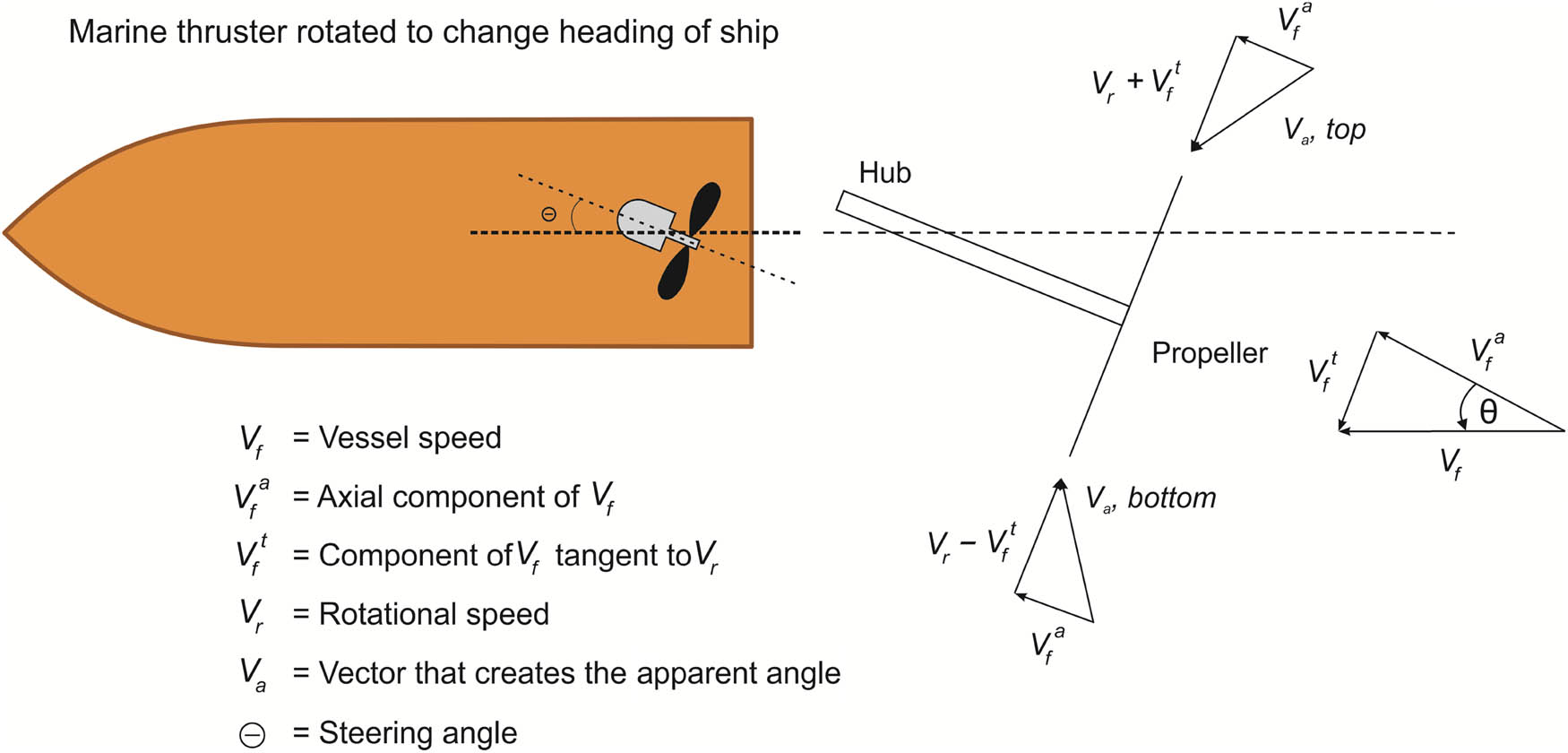
When the thruster is rotated to a steering angle to change the vessel’s heading, it causes an asymmetric load on the blades. The diagram on the right shows how the asymmetric flow causes the vector that creates the apparent angle Va and, therefore, ϕ, depending on the blade position. Note: the rotational out-of-plane components are directed towards the propeller centre in the figure to make the velocity triangle visible in a 2D perspective.
The variation in α could be countered by adjusting the pitch angle throughout each revolution. Changing the pitch at the blade’s root with a mechanism, like in the controllable pitch propellers, during each rotation is, in principle, possible. However, the mechanism might wear out quickly as ship propeller blades usually rotate several times per second. Therefore, propeller blades that automatically change pitch from the loading conditions due to their structural and material composition may be a better solution.
2.1 Deformation in passive adaptive propeller blades
The target deformation must be defined to evaluate different design choices towards a proposed design. It was decided to keep α constant throughout the propeller rotation as this should mitigate the load variation. As equation (1) only examines a steady state, the derivative of the equation is taken to explore the changes. As seen in equation (2), the angle of attack becomes equal to the pitch change minus the apparent angle change.
The change in the angle of attack equals the negative change in the apparent angle in a rigid propeller without pitch change. If the relative inflow velocity, shown in Figure 2, would increase for a given rotational velocity, the apparent angle ϕ increases, causing α to decrease. To maintain a constant α, such an increase in the relative inflow velocity would require a positive blade pitch change. Based on the same reasoning, the blade should show a negative pitch change towards a flatter pitch when the relative rotational velocity increases. The negative pitch change would cause the lift force coefficient to decrease as the blade is loaded, which causes a shed-off at higher loads. When the load on the blade decreases, the blade changes back to a more aggressive pitch. The effect can be considered a passive control of the blade deformation during operation.
While the pitch change was the sought-after effect in the blade, it was expected that other deformation modes would appear as the propeller blade deforms. For example, an expected but undesired side effect of deformation is the change in the foil’s shape, which can cause a change in the hydrodynamic characteristics. Another secondary deformation mode is the bending deflection in the propeller blade. While bending deflection is necessary to get a twist from a bending-induced twist mechanism, large deflections may cause high strains that could initiate failure mechanisms in the propeller blade.
Thus, the goal was to find design options that change the desired pitch angle while avoiding foil shape changes and excessive bending deflection. A method to quantitatively keep track of the wanted and unwanted deformation modes in the blade is essential when investigating the deformation of the propeller blades. It is described in Section 2.4.
2.2 Designing FRP propeller blade with bend-twist coupling
While metal propellers are usually cast as solid blades, the FRP propeller blades were designed as laminated shells typical for composites. Making the propeller as a hollow structure simplifies the design and production issues, but it overlooks possible augmentation of blade deformation through internal substructures, such as spars and ribs.
Previous researchers’ works on passive adaption in marine propeller blades have found good bend-twist example layups based on iterative optimisation methods described as generic algorithms [2,3]. These methods iterate possible laminate layups by varying the fibre orientation angles and the number of plies to find the best-considered layup arrangement within the boundaries assigned.
The work presented here investigated two laminate tailoring strategies for the FRP layup of the propeller blade: local stiffening patches at different places and varying orientations for unidirectional surface plies. Many possible design choices in these strategies were investigated using a systematic computerised approach to mass-produce design choices and identify good choices. An example design that combines aspects from promising design options is proposed to verify that the selected design choices contribute towards the desired deformation in a more realistic design. The investigated layup strategies and the screening of the design choices for the desired deformation are described in Section 2.3. The example layup for a passive adaptive propeller blade with the desired pitching deformation is provided in Section 3.2.
2.3 Operation scenarios and load cases on the propeller blades
The loading condition causing the deformation must be given to design a desired pitching deformation in the blades. Two manoeuvring scenarios for a ship with a propeller mounted on a thruster were considered. In the first scenario, the thruster was aligned with the vessel’s heading to cruise at a constant velocity. In the second scenario, the thruster was rotated to an 8° steering angle relative to the vessel’s travel direction to change the heading, as shown in Figure 3, giving a periodic load variation. The RPM is normalised to 1 in the first scenario and 0.96 for the other. In both scenarios, the vessel speed is the same. The vessel’s wake is neglected in the flow field analysis as the wake depends on the type of vessel considered. When simulating the first scenario, the blades are found to be similarly loaded.
In the second scenario, the blade exposed to the minimum periodic load is similarly loaded as the propeller blades exposed to cruising load. However, the blade load increases by more than 60% when the blade is exposed to the maximum periodic load. The diagram in Figure 3 shows how a turned thruster creates the flow vectors V a,top and V a,bottom, which cause variations in ϕ and α and load.
From the two operating scenarios, four different load cases emerge to be interesting, as shown in Table 1. First, the unloaded and cruising load cases were used to investigate how different layup arrangements affect the deformation. The second scenario and load cases with minimum and maximum periodic loads were used when designing the example layup.
Considered load cases
| Operation condition | Unloaded | Average cruising scenario | 8° steering angle scenario | |
|---|---|---|---|---|
| Investigated load cases | Unloaded | Cruising load | Minimum periodic load | Maximum periodic load |
The difference in apparent angle in the minimum periodic load and the maximum periodic load in the periodic load variation scenario is shown in Figure 4. The plot only shows the angle from the normalised radius of 0.3 to the propeller blade tip, as the hub is usually located at the lower radii.
![Figure 4
Change in the apparent angle in the considered periodic load variation (Figure 3) throughout the radius of the blade. The graph is based on an equation from a previous study [4].](/document/doi/10.1515/eng-2022-0419/asset/graphic/j_eng-2022-0419_fig_004.jpg)
When inspecting Figure 4, it can be seen that the change in the apparent angle is 2.3° at a radius of 0.5, 1.2° at a radius of 0.7, and 0.8° at the radius of 0.9 of the propeller blade. Based on equation (2), a negative pitch angle change of 0.8° at the radius of 0.9 between the least loaded and most loaded position in the periodic load variation scenario would counteract the 0.8 change to the apparent angle at this radius, leaving the change to the angle of attack to be zero at the explored radius. With no change in the angle of attack, there should be no change in the lift contribution. This specific deformation, 0.8° at the radius of 0.9, was set as the desired deformation when designing the example layup.
2.4 Describing propeller blade deformations
The shape of the radial cross-sections in the propeller blade models was characterised with foil parameters, as shown in Figure 5. The foil parameters used are also listed in Table 2. The foil profiles on the left of Figure 5 are only a sketch to illustrate the measurements taken and visualise how a propeller foil that deforms from the original position could look. The right part of the model shows an example with some arbitrary desirable foil parameter results. By tracking several cross-sections at different radii of a propeller blade and by describing them all with the foil parameters, it was possible to describe and quantify the propeller blades’ shape.
![Figure 5
Illustration of foil parameters in focus. The pitch and change in pitch were the primary deformation characteristics sought. The chord length is the distance from the tail to the nose of the foil. In the direction perpendicular to the chord line, the thickness (the distance between the top and bottom face) was measured. The measured distance between the camber line and the chord line in the same direction was used to calculate the camber. The camber value in the figure was divided by the initial chord line length to get the camber key performance indicator (KPI), f, as this is the convention at SINTEF Ocean [36].](/document/doi/10.1515/eng-2022-0419/asset/graphic/j_eng-2022-0419_fig_005.jpg)
Illustration of foil parameters in focus. The pitch and change in pitch were the primary deformation characteristics sought. The chord length is the distance from the tail to the nose of the foil. In the direction perpendicular to the chord line, the thickness (the distance between the top and bottom face) was measured. The measured distance between the camber line and the chord line in the same direction was used to calculate the camber. The camber value in the figure was divided by the initial chord line length to get the camber key performance indicator (KPI), f, as this is the convention at SINTEF Ocean [36].
Tracked foil parameters
| Foil parameters | Deflection (mm) | Pitch (°) | Camber | Thickness (mm) | Chord line length (mm) |
|---|---|---|---|---|---|
| Baseline foil shape | δ 0 = 0 | θ 0 | f 0/C 0 | T 0 | C 0 |
| Loaded foil shape | δ 1 | θ 1 | f 1/C 0 | T 1 | C 1 |
| Change in shape | Δδ | Δθ | Δf | ΔT | ΔC |
When the blade is unloaded, the propeller blade’s shape will be as it was after production. However, when the blade gets loaded, it deforms, causing the blade’s foil parameters to change to describe the loaded blade shape. Note that under the static load cases considered in this study, the foil parameters are constant for a given load case.
The change in the foil parameters between the two loading conditions was used to describe how the blade deformed. The deformation characteristics were the displacement of the foil profile, the change in pitch, and the warping of the foil, subdivided into changes in camber, foil thickness, and chord length, as shown in Figure 5. The thickness and camber were measured at the midpoint of the chord line in this study but could have been measured at any point(s) along the chord line.
3 Finite element analyses (FEA) and iterative design method
This section describes the FE modelling details, the iterative design method, and the design choices in the material layup analysis. The FEA was done with the software Abaqus 2017 from Dassault Systems. The iterative design method that generated the propeller blade models was programmed in the Abaqus compatible Python 2.7.4.
3.1 FE-model
The isolated solid propeller blade shape was modelled as a hollow shell model with an opening at the bottom (root) of the propeller blade.
The radial cross-sections of the foils were marked on the hollow propeller model, as shown in Figure 6. Cross-sections were measured with 0.05 radial spacing between 0.5 and 0.95 of the normalised propeller radius. Circular sections were chosen as this is the path the water travels when the propeller is rotating.
![Figure 6
Definition of the profile lines of the propeller blade. Figure from a previous study [5].](/document/doi/10.1515/eng-2022-0419/asset/graphic/j_eng-2022-0419_fig_006.jpg)
Definition of the profile lines of the propeller blade. Figure from a previous study [5].
3.2 Loads and boundary condition (BC)
A multi-point constraint (MPC) connected displacements and rotations along the bottom edge to an Abaqus reference point in the centre of rotation, as shown in Figure 7(a). A BC then fixed the reference point in all degrees of freedom. Together the MPC and BC fix the bottom edge of the propeller, neglecting any compliance or complex mechanisms in the propeller blade-to-hub connection, leaving only the deformation of the blade for analysis.
![Figure 7
Two Abaqus screenshots. (a) Shows the BC and MPC used in the FE model and (b) shows the pressure distribution mapped on the propeller blade. Figure from a previous study [4].](/document/doi/10.1515/eng-2022-0419/asset/graphic/j_eng-2022-0419_fig_007.jpg)
Two Abaqus screenshots. (a) Shows the BC and MPC used in the FE model and (b) shows the pressure distribution mapped on the propeller blade. Figure from a previous study [4].
The loads in the two operating scenarios investigated were applied to the blades as first-order pressure distributions provided by Kongsberg Maritime [38]. The load case is applied as pressure distributions derived by modelling the propeller cruising forward at a constant speed and propeller rev, plus an 8° steering of the thruster. the mapping of pressure distribution onto the propeller is shown in Figure 7(b).
Due to the complex geometry of the propeller surfaces, triangular shell elements were the only viable option for the mesh. A convergence study was conducted to establish what mesh characteristics were necessary to capture the deformation characteristics sufficiently. The element types STRI65, S3, and S3R were considered. When doing the convergence study, the shell elements were assigned the Young’s modulus of brass, 134 GPa. For the shell element thickness, 5 mm was chosen, modelling a hollow sheet-metal-like structure. Convergence was found for all elements smaller than 4 mm [4,5]. The S3 and S3R elements showed a 1.5% smaller deformation, explained by the fact that linear triangular elements occasionally show some artificial stiffness. 4 mm large quadratic STRI65 elements were the best choice based on speed and convergence was selected for the further FE-models.
3.3 Material layup analysis
Propeller blade models were generated based on individual design options, and the deformation in the blade was described with the foil parameters in Section 2.4. Some of the material layups in the models were inherently unrealistic as this process was intended to isolate each design’s deformation contribution. These layup models were still examined to determine if the design option would contribute to the desired deformation. Since the deformations were estimated with linear solutions, the computational cost was low. The low cost allowed a brute force computational approach with over 2,000 models being generated, simulated, observed, and evaluated.
The first of the strategies, local stiffening patches, was investigated by partitioning the hollow model into sections, as shown in Figure 8(a) and (b). Then, the sections were iteratively and systematically stiffened for each partition scheme, creating hundreds of models, as shown in Figure 9. Apart from the horizontal (a) and the vertical (b) partition scheme in Figure 8, a 45° and a 135° partition series were also simulated. In these simulations of local stiffening patches, the anisotropy of FRP was not considered, and the stiffening patches were isotropic.

(a) and (b) A few sectional design series in different local stiffening patch strategies. The coordinate system in (c) is used when angling UD fibres and woven fabrics.

A sample of the model series with various simulations of local stiffening patches. The green partitions are relatively soft, and the white ones are relatively stiff. Different stiffness ratios are tested as well.
The second strategy, UD-surface plies, was investigated by draping an FRP UD ply at different angle configurations over the propeller blade’s surfaces, as shown in Figure 10. The UD ply was rotated with 10° increments in the coordinate system shown in Figure 8(c). With 10° increments, a total of 17 different models were made for each side, giving a total of 34 simulations. The material properties from a UD carbon fibre-reinforced epoxy datasheet were used in the simulation [40].

The UD ply on one side is rotated by 10° increments for each model in the design series, while the UD ply on the other side is kept in the 0° direction.
A concise screening criterion was required to evaluate whether a design option’s calculated responses could be promising. Two KPIs were chosen, pitch per displacement (Δθ/δ 1) and camber change (Δf). The pitch per displacement was chosen as the main sought-after effect maximising the bend-twist coupling. Camber is chosen as a secondary KPI to monitor undesired foil warping. The parameters of chord line length and foil thickness were assumed to be best controlled through possible internal substructures and were not considered.
4 Results
4.1 Systematic, iterative FE analysis
Only some examples are shown here, as thousands of models with their respective deformation were generated in the material layup analysis. A plot like the one in Figure 11 was made for each generated model. The simulated foil characteristics are quantified in the four top windows in Figure 11 for normalised radius positions 0.6, 0.7, 0.8, and 0.9. The windows below show the bending (deflection) and twist as well as the KPIs, pitch change per deflection and camber.
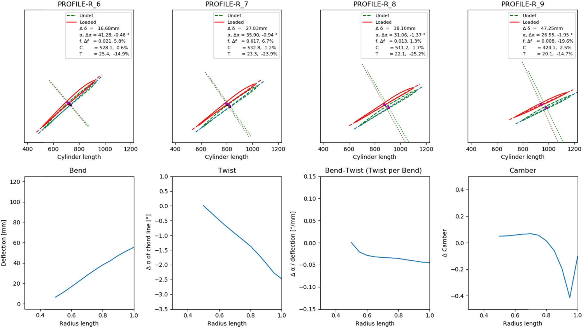
Example of simulated deformations calculated by the FE model. Here the layup LM737 from Section 3.2 under maximum load is shown.
The deformations in each model simulating the design choices in the material layup analysis are compared in the following plots. In Figures 12 and 13, two plots compare two design series generated based on each layup strategy. The desired characteristics for the blade were defined as much twisting (the ones circled in black in the second plot) and little foil shape change (the ones circled in black in the fourth plot). The designs circled in red in the fourth plot were decided to have much pitch change. No exact limit was chosen here, but comparisons were performed for each investigated series. To sum up, while several design choices in Figure 12 show the desired pitch change twisting, they should also show little negative foil change characteristics to be viable, as foil shape change affects the hydrodynamics of the blade.
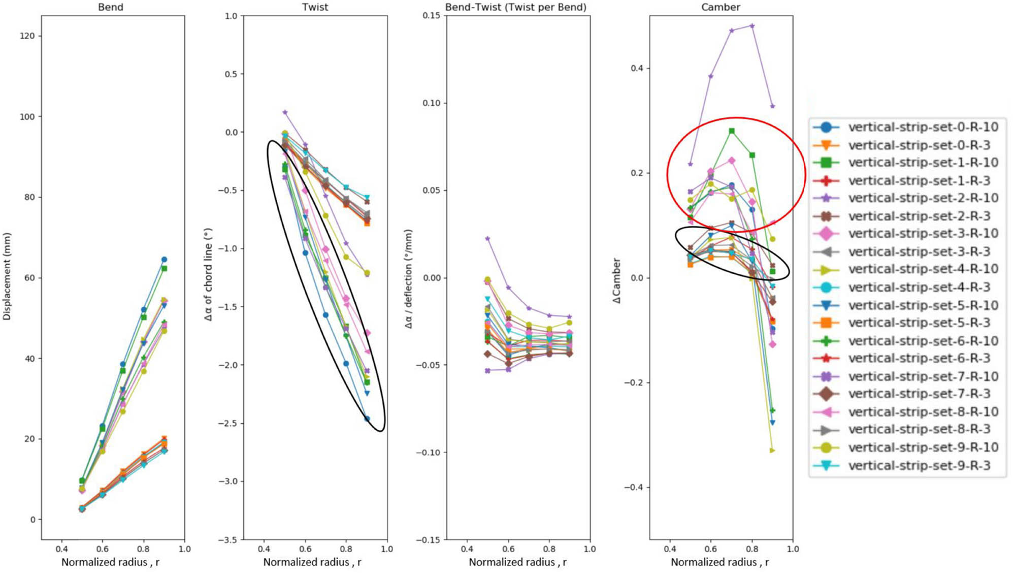
Comparison of blade characteristics of a design series exploring the vertical reinforcements shown in Figure 8(b). The convention following gives the legend names: First, “vertical strip” to indicate what type of design choice was explored, then the set and number show the number allocated to the design choice in the design series and the relative stiffening in the patch. The design choices inside both black circles are desirable due to twisting potential. The ones in the red circle and above are undesirable due to foil warping. When looking at Figure 8(a) and (b), the set number indication count starts at 0 to the left for the vertical and right for the horizontal.
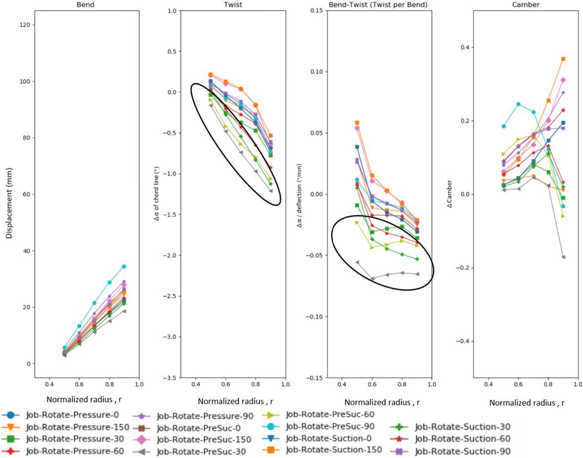
Comparison of blade characteristics of some designs with changing the orientation of the UD-surface plies, as shown in Figure 10. The legend names are given by the convention: Job-Rotate, indicating that this is the particular fibre orientation simulation, followed by a description of which side of the propeller the ply was on (pressure or suction side, or both) and what angles were used. Not all investigated angles are shown here.
4.2 Example FRP layup
The analysis of local stiffening patches found that both stiffening towards the leading edge and stiffening certain other locations improve the KPI pitch per deflection, as shown in Figure 12. The analysis of different orientations of UD-surface plies showed that the best pitch per deflection is obtained for a fibre orientation of 30° on both sides of the propeller blade, as shown in Figure 13. This indicates that these design choices contribute towards the desired deformation.
The more realistic example design was made by adding several UD-surface plies and a local stiffening patch to a quasi-isotropic base layup. The material properties in the datasheets for the carbon fibre-reinforced epoxy product series XPREG from Easy Composites were used in the example design [40,41]. The local stiffening patch shown in Figure 14 and the 30° plies were combined with surface and backing plies for the proposed example layup. A structural requirement was added as large deflections may cause strains that initiate failure mechanisms in the FRP material. The strains should not exceed 1.2%, 80% of the ultimate strain value for similar carbon fibre prepreg materials (1.5%) [42]. (This strain limit is somewhat arbitrarily chosen and needs to be evaluated in a structural reliability analysis). The layup is named LM737, and an overview of this layup is given in Figure 15 and Table 3. For the coordinate system used, see Figure 8(c). The layup has 15 plies on the suction side and three extra plies making up the stiffening patch (yellow part in Figure 14). The yellow patch is referred to as a mast, as it seems like the blade pivots around an axis created by this stiffening patch. The pressure side is made up of 12 plies, plus one extra backing ply towards the leading edge of the blade.

Layup regions in the example blade layup LM737 which exhibits bend-twist characteristics. The pressure side of the blade is to the right, and the suction side on the left.

Comparison of a solid propeller, a 5 mm hollow isotropic brass shell propeller and the LM737 bend-twist layup.
Layup for the passive adaptive propeller blade design shown in Figure 14
| Regions in Figure 14 | FRP layup in Figure 14 |
|---|---|
| 1 | [0, 30, 75, 30, 30, 75, 30, 30, 75, 30, 30, 75, 30, 75, 30] |
| 2 | [0, 30, 75, 30, 30, 75, 30, 0, 30, 0, 30, 75, 30, 30, 75, 30, 75, 30] |
| 3 | [60, 0, 60, 0, −30, −30, 0, −30, −30, 0, 90, 0, 60] |
| 4 | [60, 0, 0, −30, −30, 0, −30, −30, 0, 90, 0, 60] |
CF materials are indicated as follows: italics indicates backing plies, bold indicates UD, and underline indicates surface plies.
In Figure 15, the deformation of the FE shell model with the LM737 layup is compared to a solid metal (brass) propeller blade FE model and a hollow quasi-isotropic composite propeller blade. In the quasi-isotropic layup, seven 0/90 and seven ± 45 backing plies were used to cover the entire surface on both sides of the propeller, an overengineered material layup compared to the proposed propeller bend-twist layup. The models were simulated with the periodic load case to determine the periodic pitch change in the blade for the minimum periodic load and the maximum periodic load.
Figure 15 shows that the solid metal propeller has a positive pitch change when deforming, opposite to what is desired. However, the hollow composite shell propeller has the desired negative pitch change. This entails that going from a solid structure to a hollow shell structure already contributes toward bend-twist deformation for the investigated propeller geometry.
It can be seen in Figures 11 and 15 that the LM737 layup shows little bending deflection and twist close to the fixed root. Moving to larger radii, the twist per bend increases. The LM737 design shows a pitch change of −0.43° and −0.81° at the respective radii 0.7 and 0.9 between the minimum periodic load case and the maximum periodic load case. The 0.81° change at radius 0.9 counters the variation here. The FE model calculated that the propeller blade shows a considerable strain close to the leading edge on the pressure side when loaded (Figure 16). The strain in this area is probably due to the double curvature there and due to the area being close to the blade´s centre of pressure. The structural integrity of the LM732 layup is addressed here by the maximum 1.2% strain criterion. Under maximum periodic load, the example layup shows a maximum strain of 1.16%, as shown in Figure 16. Note that if the maximum allowed strain of 1.2% is too high, more local stiffening patches at the highest strains can rectify the situation.

Strain values in fibre direction in the propeller blade layup under the maximum periodic load. A high strain is seen close to the leading edge on the pressure side of the propeller blade. The strain is found to be below the set 1.2% max strain criterion.
5 Discussion
5.1 Composite marine propellers
Blades of marine ship propellers work at a pretty high RPM in a dense medium, so small changes in geometry become critical for the hydrodynamic performance of the blades. While the load increases by over 60% during the periodic load case, the change in the apparent angle (and angle of attack), which causes the load change, is only around 0.6–2.3°, as shown in Figure 4. The twist deformation in a passive adaptive blade only needs to make small changes to the pitch to keep α about constant, minimising load fluctuations.
In the example blade design, the pitch changes due to the varying deformation in the periodic load variation and when the propeller goes from unloaded to cruising load. Therefore, the most efficient shape of the propeller should be achieved when the propeller is in cruising condition. Traditional metal propellers show negligible deformation, so for them, the unloaded shape and cruising shape are considered identical. The main advantage of composite propellers appears under periodic loading conditions, such as turning the ship, where the loads on the blades vary under each rotation. For the blade considered here, a 0.8° pitch change at a radius of 0.9 is sufficient to keep the blade significantly better aligned to the changing water flow.
More precisely, the pitch should change along the radius of the blade. In this study, the positions 0.7 and 0.9 of the total radius of the propeller were in focus. The 0.7 radius was investigated as this radius is essential for the total load of the blade [36], while the 0.9 radius is vital for the cavitation and noise produced by the blade [38]. Commercial propeller designs should address all these aspects. This study concentrates on achieving the desired bend-twist performance at the 0.9 radius of the blade.
5.2 Iterative computational method
The iterative approach was chosen to investigate the design options systematically. This would include intuitive choices and design options one would usually not consider, like the patch in Figure 14, later referred to as a mast or flange. The investigated parameters were local stiffening patches and fibre orientation of unidirectional plies. The results showed that a mast was a good choice in the local stiffening patch strategy. Stiffening towards the leading edge was also a good design choice for a local stiffening patch. The fibre orientations of 30° on both surfaces and 60° on the pressure side were good choices for unidirectional plies, as shown in Figure 13.
The evaluation of these design choices was based on a set of critical parameters: deflection, pitch, camber, chord line length, and foil thickness. This was an excellent way to describe the shape characteristics. Unfortunately, for some design choices, very meaningless shapes emerged. The promising solutions could be well described with the three main parameters, pitch change, bending deflection, and camber. Good solutions were characterised by having large negative pitch change while changing the camber parameter as little as possible.
The simulations in the iterative process were done with linear FE analysis and a fixed pressure distribution derived with 1-way FSI. Kumar showed that the deformation decreases by 15% when considering 2-way FSI compared to 1-way in passive adaptive FRP propellers. This result indicates that the FEA used in the design method is sufficiently accurate to identify the deformation contribution from the design choices. Furthermore, the deformation observed in the models based on the different considered design choices in the design strategies local stiffening patches and the fibre orientation of the unidirectional plies clearly showed which choices work and which ones do not.
5.3 Promising design choices
A stiffing mast spanning from the root to the top of the blade gave good results when placed slightly towards the leading edge, as shown in Figure 14. The stiffening mast reduces the bending deflections and functions as a pivot in the circumferential direction. Another stiffening strategy is reinforcing close to the leading edge. By stiffening the leading edge, the tail of the foil is free to move while the leading edge is kept in place.
The 30° fibre orientation on unidirectional fibres contributes well towards the desired bend-twist deformation, an expected result when considering that the bend-twist coupling in a flat FRP plate maximises at 30° [43]. However, a more unexpected discovery was that a 60° fibre orientation on the pressure surface also contributed quite well towards bend-twist coupling.
5.4 The proposed design
The iterative study was done on the metal propeller geometry, checking simple design concepts. The most promising design choices were the mast and the 30° fibre orientation. A more realistic blade layup design based on the more promising design choices were then made. These were incorporated into an FRP design with a quasi-isotropic base layup. Static strength was obtained by keeping the maximum strain below 1.2%. This strain value was arbitrarily set, it gives roughly a safety factor of 1.2 before fibre failure. The example is seen as one possible solution, not the solution. Safety factors and long-term behaviour need to be considered in the future but are outside the scope of this study.
It is clear from Figure 11 that the proposed layup, LM737, exhibits bend-twist coupling. When comparing the pitch change achieved in the design to the perceived change in apparent angle in the second operating scenario (in Figure 4), the achieved pitch angle change is comparable to the periodic change in apparent angle in the second scenario. At radius 0.7, 0.8, and 0.9, the change in α is, respectively, reduced by 35.5%, 59%, and 101%. For all considered load cases (Table 1), the pitch change at radius 0.9 between unloaded and load cases was −1.07° for the cruising scenario, −1.14° for the minimum loaded blade position, and −1.95° for the maximum loaded blade position. In addition, the example design showed a higher twisting coefficient when exposed to the maximum periodic loading compared to the cruising and minimum periodic loading cases, implying that the design exploits the changes in the load characteristics between the minimum and maximum periodic load and shows more efficient twisting per deformation under higher loads [4].
The example design also shows that the secondary deformation effects, camber, and deflection vary quite a bit. First, the propeller blade changes shape between unloaded and cruising scenarios, and then the blade shape changes again when the thruster is turned for steering periodically as the blades go through the least and most loaded position. It is seen in the deformation mode analysis that during the periodic load condition, the camber is reduced by 8% at blade radius of 0.9 under minimum load, which decreases further to a 19% camber reduction, warping the foil profile. Still, when comparing the camber for the three investigated loads, the camber change is roughly between +14% and −14% for all three investigated load cases in the LM737 layup at all other radii.
5.5 Comparison and contribution
In Table 4, the blade of Kumar and Wurm [3] was compared to the blade design proposed in this study. The blade design of Kumar and Wurm is used in this publication as it has clearly stated the twist and deflection, in addition to propeller performance. While it might seem at first glance that the bend-twist characteristics of Kumar and Wurm are very similar to this work, the blade in this study is half the diameter of Kumar and Wurm’s blade. Longer blades, like wind turbine blades, often exhibit much larger twists due to their increased length. The longer length affects the blade-twist effect on twist as the twisting manifests throughout the blade length when the propeller bends [18,26,44,45]. The novelty of the proposed design lies in the fact that it achieves nearly identical twist and bend-twist coefficient values compared to Kumar and Wurm’s blade design, even though the proposed design has only half the blade length.
Deformation characteristics of the proposed propeller design compared to Kumar and Wurm’s blade design
| Propeller blade models | Deflection (mm) | Twist (°) | Twist per deflection (°/mm) | ||||||
|---|---|---|---|---|---|---|---|---|---|
| Radius | 0.5 | 0.7 | 0.9 | 0.5 | 0.7 | 0.9 | 0.5 | 0.7 | 0.9 |
| Kumar and Wurm’s design | 15 | 31 | 47 | 0.5 | 1.3 | 2.3 | 0.03 | 0.04 | 0.05 |
| Proposed design under maximum load | 7 | 27 | 47 | 0 | 0.9 | 1.9 | 0 | 0.03 | 0.04 |
Another aspect here is that these two propellers are made up of entirely different blades, operating in very different load cases, and that it is still challenging to extract clear design rules for passive adaptive composite propellers. The blade in this study is mounted on a thruster and loaded with approximately 26 kN. The propeller of Kumar and Wurm is intended as a driveshaft propeller, and the blade load is approximately 2 kN [3]. The difference in loading makes the comparison between the propellers difficult without a 2-way FSI analysis.
5.6 Other considerations
A surprising discovery is that going from a solid propeller design to a hollow design already provides some desired bend-twist coupling. The hollow baseline quasi-isotropic composite design shows a significant pitch change per deformation, while the solid design does not show any. However, since the deformation is minimal, the absolute change in pitch is minimal.
The FRP layup propeller is quite deformed when going from unloaded to loaded with cruising (or baseline) load, but there are more subtle differences between the three operational load cases. The initial deformation brings up the idea of a propeller design that considers this initial deformation when making the unloaded shape for commercial composite ship propeller designs. As the propeller also deflects a bit, there is a possibility that the amount of produced blade lift direction would change, lessening how much of the blade contribution could be used. In the investigated case, the blade deflected a maximum of 5.5 cm, causing a 5° angle change to the tip, which with cosine, the thrust should diminish around 1%. Still, if the deflection becomes too much for practical applications, one could again consider this initial deformation when making the unloaded propeller shape and deciding on the layup.
It would be interesting to simulate the example design with 2-way FSI simulations to obtain more accurate deformations and performance characteristics of the design. In addition, dynamic analysis of the example design should be done before any practical use, but comparable composite propellers showed modal frequencies to be at least 3–4 times higher than the propeller RPM [25], which is promising.
6 Conclusion
An example of a propeller blade design was made that mitigates periodic load variations with a bend-twist deformation that causes a load shed-off. The example design shows a negative pitch change that fully counters the periodic variations in the water flow at the radius of 0.9 in the propeller blade when modelled with one-way FSI. The hydrodynamic profile of the propeller blade remains quite constant, indicating that the blade would keep its hydrodynamic performance. A computational method was developed to identify which design choices show the desired bend-twist deformation.
An iterative, systematic FEA-based computational method was developed to find promising design choices. The focus was on composite marine propeller blades without internal structures. The method calculated the deformations of the blade under given loading conditions, changing the location of local stiffness and applying different fibre orientations in the surface shells. Thousands of design choices were tested, focusing on deformation and ignoring strength.
Characterising the deformations of the propeller blade’s complicated geometry required identifying a few critical parameters. These were the pitch and the camber (describing the hydrodynamic foil profile) along the radius of the blade. These changed when the loads deformed the propeller blade. This change in the critical parameters was examined to identify design choices that show significant negative pitch change per deflection and little change to the camber in the deformation.
The best deformation characteristics were obtained for a vertical reinforcement line (mast) located roughly at the middle of the blade and for the fibre orientations of 30° in the laminate surface shells. The mast reduces radial deflections and functions as a pivot line, and the 30° laminate orientation causes the material bend-twist coupling. Stiffening the leading edge was also found to yield the desired deformation.
A realistic example layup was chosen based on the identified good design choices and considering static strength. The example had 30° UD plies, a mast, and backing plies in a quasi-isotropic stacking. Global strains were limited to 1.2% strain under maximum load. The reduced pitch between the maximum periodic load and the minimum periodic load was 0.8° at 0.9 of the total radius length. The total pitch change in the FRP design at radius 0.9 was 1.95°, with a deflection of 47.25 mm, between the unloaded and maximum periodic load case.
In comparison, the solid metal propeller has a very small pitch change of 0.06° and a deflection of 4.25 mm at the maximum periodic load case. The pitch changes only due to the geometric shape, and not due to material´s characteristics.
This work shows that a typical propeller blade geometry can be made in composites to design bend-twist characteristics in the blade. However, to fully use the potential of composite propellers, the entire propeller blade geometry should be redesigned, taking the initial deformation of the blade into account.
Acknowledgments
This work was performed within Work Package 4 of the FleksProp project. NTNU and SINTEF Ocean did the work in collaboration with Kongsberg Maritime Ulsteinvik.
-
Funding information: The research was funded by The Research Council of Norway, grant No. 267495 and KONGSBERG Maritime Ulsteinvik.
-
Conflict of interest: The authors declare no conflict of interest.
-
Data availability statement: The data presented in this study are available within the article and on request from the authors.
References
[1] Koko TS, Shahin K, Akpan UO, Norwood M, et al. Review of composite propeller developments and strategy for modeling composite propellers using PVAST. Halifax, Canada: Defence R&D Canada-Atlantic; 2012.Search in Google Scholar
[2] Paik B-G, Kim GD, Kim KY, Seol HS, Hyun BS, Lee SG, et al. Investigation on the performance characteristics of the flexible propellers. Ocean Eng. 2013;73:139–48.10.1016/j.oceaneng.2013.09.005Search in Google Scholar
[3] Kumar J, Wurm F-H. Bi-directional fluid–structure interaction for large deformation of layered composite propeller blades. J Fluids Struct. 2015;57:32–48.10.1016/j.jfluidstructs.2015.04.007Search in Google Scholar
[4] Rømcke E. The characterization of deformation modes and production of passive adaptive composite marine propellers, in MTP. Trondheim: NTNU; 2020.Search in Google Scholar
[5] Mark L. Design and fabrication of a passively adaptive carbon fiber propeller, in MTP. Trondheim: NTNU; 2020.Search in Google Scholar
[6] Ølnes J. Design modeling and production of a passive adaptive composite marine propeller blade, in MTP. Trondheim: NTNU; 2020.Search in Google Scholar
[7] Lee Y-J, Lin C-C. Optimized design of composite propeller. Mech Adv Mater Struct. 2004;11(1):17–30.10.1080/15376490490257639Search in Google Scholar
[8] Zhang X, Hong Y, Yang F, Xu Z, Zhang J, Liu W, et al. Propulsive efficiency and structural response of a sandwich composite propeller. Appl Ocean Res. 2019;84:250–8.10.1016/j.apor.2019.01.005Search in Google Scholar
[9] Liu Z, Young YL. Utilization of bend–twist coupling for performance enhancement of composite marine propellers. J Fluids Struct. 2009;25(6):1102–16.10.1016/j.jfluidstructs.2009.04.005Search in Google Scholar
[10] Liu Z, Young YL. Utilization of deformation coupling in self-twisting composite propellers. Proceedings of 16th International Conference on Composite Materials. Kyoto, Japan: 2007.Search in Google Scholar
[11] Carlton J. Marine propellers and propulsion. 4th ed. London, UK: Butterworth-Heinemann; 2018.10.1016/B978-0-08-100366-4.00002-XSearch in Google Scholar
[12] Savio L, Kourosh K. Open water characteristics of three model scale flexible propellers. MARINE VIII: proceedings of the VIII International Conference on Computational Methods in Marine Engineering. CIMNE; 2019.Search in Google Scholar
[13] Rise JE. In: Rokvam S, editor. Velocity Triangle and Pressure distributions for investigated propeller geometry. Ulsteinvik, Norway: Kongsberg Maritime; 2019.Search in Google Scholar
[14] Rokvam SØ, NPV, Mark L, Rømcke E, Ølnes J, Savio L, Echtermeyer AT. Designing bend-twist deformation in composite ship propeller blades through fiber reinforced plastics arrangement in surface laminates. Not Published. 2021.Search in Google Scholar
[15] Das HN, Kapuria S. On the use of bend–twist coupling in full-scale composite marine propellers for improving hydrodynamic performance. J Fluids Struct. 2016;61:132–53.10.1016/j.jfluidstructs.2015.11.008Search in Google Scholar
[16] Dwyer W, Rogers J. Aeroelastically tailored propellers. SAE Technical Paper; 1977.10.4271/770455Search in Google Scholar
[17] Ong C, Wang J, Tsai S. Design, manufacture and testing of a bend-twist D-spar. 37th Aerospace Sciences Meeting and Exhibit; 1999.10.2514/6.1999-25Search in Google Scholar
[18] Young YL, Garg N, Brandner PA, Pearce BW, Butler D, Clarke D, et al. Load-dependent bend-twist coupling effects on the steady-state hydroelastic response of composite hydrofoils. Compos Struct. 2018;189:398–418.10.1016/j.compstruct.2017.09.112Search in Google Scholar
[19] Murray RE, Nevalainen T, Gracie-Orr K, Doman DA, Pegg MJ, Johnstone CM. Passively adaptive tidal turbine blades: Design tool development and initial verification. Int J Mar Energy. 2016;14:101–24.10.1016/j.ijome.2016.02.001Search in Google Scholar
[20] Molland AF, Turnock SR. The design and construction of model ship propeller blades in hybrid composite materials. Compos Manuf. 1991;2(1):39–47.10.1016/0956-7143(91)90157-CSearch in Google Scholar
[21] Lin G-F. Comparative stress/deflection analyses of a thick-shell composite propeller blade. Fort Belvoir, USA: David Taylor Research Center; 1991.Search in Google Scholar
[22] Nicholls-Lee RF, Turnock SR, Boyd SW. Application of bend-twist coupled blades for horizontal axis tidal turbines. Renew Energy. 2013;50:541–50.10.1016/j.renene.2012.06.043Search in Google Scholar
[23] Fedorov V, Berggreen C. Bend-twist coupling potential of wind turbine blades. Journal of Physics: Conference Series. IOP Publishing; 2014.10.1088/1742-6596/524/1/012035Search in Google Scholar
[24] Leone S, Testa C, Greco L, Salvatore F. Computational analysis of self-pitching propellers performance in open water. Ocean Eng. 2013;64:122–34.10.1016/j.oceaneng.2013.02.012Search in Google Scholar
[25] Barber RB, Ducoin A, Wildy SJ, Codrington JD, Leroyer A. Coupled modal simulation of a composite propeller blade subjected to steady and dynamic loading. In: Proceedings of the Sixth International Symposium on Marine Propulsors. Rome, Italy: 2019.Search in Google Scholar
[26] Murray R, Gracie K, Doman DA, Pegg MJ, Johnstone CM. Design of a passively adaptive rotor blade for optimized performance of a horizontal-axis tidal turbine. European Wave and Tidal Energy Conference. Aalborg, Denmark; 2013.Search in Google Scholar
[27] Herath MT, Prusty BG, Yeoh GH, Chowdhury M, John NS. Development of a shape-adaptive composite propeller using bend-twist coupling characteristics of composites. In: Proceedings of the Third International Symposium on Marine Propulsors. Tasmania, Australia: ISMP; 2013. p. 128–135.Search in Google Scholar
[28] Barnes RH, Morozov EV. Structural optimisation of composite wind turbine blade structures with variations of internal geometry configuration. Compos Struct. 2016;152:158–67.10.1016/j.compstruct.2016.05.013Search in Google Scholar
[29] Vijayanandh R, Venkatesan K, Senthil Kumar M, Raj Kumar G, Jagadeeshwaran P, Raj Kumar R. Comparative fatigue life estimations of Marine Propeller by using FSI. J Phys Conf Ser. 2020;1473(1):012018.10.1088/1742-6596/1473/1/012018Search in Google Scholar
[30] Savio L, Sileo L, Kyrre Ås S. A comparison of physical and numerical modeling of homogenous isotropic propeller blades. J Mar Sci Eng. 2020;8(1):21.10.3390/jmse8010021Search in Google Scholar
[31] Maung PT, Prusty BG, Phillips AW, St John NA. Curved fibre path optimisation for improved shape adaptive composite propeller blade design. Compos Struct. 2021;255:112961.10.1016/j.compstruct.2020.112961Search in Google Scholar
[32] Paboeuf S, Collier B, Muller P, Berthelot P. Design method application for a propeller in composite materials. Practical design of ships and other floating structures. Proceedings of the 14th International Symposium. Singapore: Springer; 2021. p. 539–549.10.1007/978-981-15-4624-2_32Search in Google Scholar
[33] Rokvam SØ, Vedvik NP, Mark L, Rømcke E, Ølnes JS, Savio L, et al. Experimental verification of the elastic response in a numeric model of a composite propeller blade with bend twist deformation. Polymers. 2021;13(21):3766.10.3390/polym13213766Search in Google Scholar PubMed PubMed Central
[34] Hussain M, Abdel-Nasser Y, Banawan A, Ahmed YM. FSI-based structural optimization of thin bladed composite propellers. Alex Eng J. 2020;59(5):3755–66.10.1016/j.aej.2020.06.032Search in Google Scholar
[35] Shiraishi K, Sawada Y, Arakawa D. Deformed shape estimation for flexible composite marine propellers by image registration. J Mar Sci Technol. 2023;8:221–33.10.1007/s00773-022-00918-1Search in Google Scholar
[36] Luca Savio LS. Hydrodynamic aspects of flexible isopropic propellers. NTNU; Editor. 2019.Search in Google Scholar
[37] Harsha Vardhan D, Ramesh A, Chandra Mohan Reddy B. A review on materials used for marine propellers. Mater Today Proc. 2019;18:4482–90.10.1016/j.matpr.2019.07.418Search in Google Scholar
[38] Rise JE. . Design goals, velocity triangle, propeller considerations and pressure distributions for investigated propeller geometry; MTP N, editor. 2019. Email.Search in Google Scholar
[39] NASA NH 2021; https://www.grc.nasa.gov/www/k-12/airplane/incline.html.Search in Google Scholar
[40] EasyComposites. XC130 autoclave cure component prepreg technical datasheet. 2017; https://media.easycomposites.co.uk/datasheets/EC-TDS-XC130-Prepreg.pdf.Search in Google Scholar
[41] EasyComposites. XC110 out-of-autoclave component prepreg technical datasheet. 2017; https://media.easycomposites.co.uk/datasheets/EC-TDS-XC110-Out-of-Autoclave-Component-Prepreg.pdfSearch in Google Scholar
[42] Truong GT, Tran HV, Choi K-K. Tensile behavior of carbon fiber-reinforced polymer composites incorporating nanomaterials after exposure to elevated temperature. J Nanomaterials. 2019;2019:4139208.10.1155/2019/4139208Search in Google Scholar
[43] Murray RE, Doman DA, Pegg MJ. Finite element modeling and effects of material uncertainties in a composite laminate with bend–twist coupling. Compos Struct. 2015;121:362–76.10.1016/j.compstruct.2014.11.035Search in Google Scholar
[44] Fedorov V, Dimitrov N, Berggreen C, Krenk S, Branner K, Berring P. Investigation of structural behaviour due to bend-twist couplings in wind turbine blades. Proceedings of the 17th International Conference of Composite Materials (ICCM). Edinburgh, UK: 2009.Search in Google Scholar
[45] Cox, K, Echtermeyer A. Structural design and analysis of a 10MW wind turbine blade. Energy Procedia, 2012;24:194–201.10.1016/j.egypro.2012.06.101Search in Google Scholar
© 2023 the author(s), published by De Gruyter
This work is licensed under the Creative Commons Attribution 4.0 International License.
Articles in the same Issue
- Regular Articles
- Design optimization of a 4-bar exoskeleton with natural trajectories using unique gait-based synthesis approach
- Technical review of supervised machine learning studies and potential implementation to identify herbal plant dataset
- Effect of ECAP die angle and route type on the experimental evolution, crystallographic texture, and mechanical properties of pure magnesium
- Design and characteristics of two-dimensional piezoelectric nanogenerators
- Hybrid and cognitive digital twins for the process industry
- Discharge predicted in compound channels using adaptive neuro-fuzzy inference system (ANFIS)
- Human factors in aviation: Fatigue management in ramp workers
- LLDPE matrix with LDPE and UV stabilizer additive to evaluate the interface adhesion impact on the thermal and mechanical degradation
- Dislocated time sequences – deep neural network for broken bearing diagnosis
- Estimation method of corrosion current density of RC elements
- A computational iterative design method for bend-twist deformation in composite ship propeller blades for thrusters
- Compressive forces influence on the vibrations of double beams
- Research on dynamical properties of a three-wheeled electric vehicle from the point of view of driving safety
- Risk management based on the best value approach and its application in conditions of the Czech Republic
- Effect of openings on simply supported reinforced concrete skew slabs using finite element method
- Experimental and simulation study on a rooftop vertical-axis wind turbine
- Rehabilitation of overload-damaged reinforced concrete columns using ultra-high-performance fiber-reinforced concrete
- Performance of a horizontal well in a bounded anisotropic reservoir: Part II: Performance analysis of well length and reservoir geometry
- Effect of chloride concentration on the corrosion resistance of pure Zn metal in a 0.0626 M H2SO4 solution
- Numerical and experimental analysis of the heat transfer process in a railway disc brake tested on a dynamometer stand
- Design parameters and mechanical efficiency of jet wind turbine under high wind speed conditions
- Architectural modeling of data warehouse and analytic business intelligence for Bedstead manufacturers
- Influence of nano chromium addition on the corrosion and erosion–corrosion behavior of cupronickel 70/30 alloy in seawater
- Evaluating hydraulic parameters in clays based on in situ tests
- Optimization of railway entry and exit transition curves
- Daily load curve prediction for Jordan based on statistical techniques
- Review Articles
- A review of rutting in asphalt concrete pavement
- Powered education based on Metaverse: Pre- and post-COVID comprehensive review
- A review of safety test methods for new car assessment program in Southeast Asian countries
- Communication
- StarCrete: A starch-based biocomposite for off-world construction
- Special Issue: Transport 2022 - Part I
- Analysis and assessment of the human factor as a cause of occurrence of selected railway accidents and incidents
- Testing the way of driving a vehicle in real road conditions
- Research of dynamic phenomena in a model engine stand
- Testing the relationship between the technical condition of motorcycle shock absorbers determined on the diagnostic line and their characteristics
- Retrospective analysis of the data concerning inspections of vehicles with adaptive devices
- Analysis of the operating parameters of electric, hybrid, and conventional vehicles on different types of roads
- Special Issue: 49th KKBN - Part II
- Influence of a thin dielectric layer on resonance frequencies of square SRR metasurface operating in THz band
- Influence of the presence of a nitrided layer on changes in the ultrasonic wave parameters
- Special Issue: ICRTEEC - 2021 - Part III
- Reverse droop control strategy with virtual resistance for low-voltage microgrid with multiple distributed generation sources
- Special Issue: AESMT-2 - Part II
- Waste ceramic as partial replacement for sand in integral waterproof concrete: The durability against sulfate attack of certain properties
- Assessment of Manning coefficient for Dujila Canal, Wasit/-Iraq
- Special Issue: AESMT-3 - Part I
- Modulation and performance of synchronous demodulation for speech signal detection and dialect intelligibility
- Seismic evaluation cylindrical concrete shells
- Investigating the role of different stabilizers of PVCs by using a torque rheometer
- Investigation of high-turbidity tap water problem in Najaf governorate/middle of Iraq
- Experimental and numerical evaluation of tire rubber powder effectiveness for reducing seepage rate in earth dams
- Enhancement of air conditioning system using direct evaporative cooling: Experimental and theoretical investigation
- Assessment for behavior of axially loaded reinforced concrete columns strengthened by different patterns of steel-framed jacket
- Novel graph for an appropriate cross section and length for cantilever RC beams
- Discharge coefficient and energy dissipation on stepped weir
- Numerical study of the fluid flow and heat transfer in a finned heat sink using Ansys Icepak
- Integration of numerical models to simulate 2D hydrodynamic/water quality model of contaminant concentration in Shatt Al-Arab River with WRDB calibration tools
- Study of the behavior of reactive powder concrete RC deep beams by strengthening shear using near-surface mounted CFRP bars
- The nonlinear analysis of reactive powder concrete effectiveness in shear for reinforced concrete deep beams
- Activated carbon from sugarcane as an efficient adsorbent for phenol from petroleum refinery wastewater: Equilibrium, kinetic, and thermodynamic study
- Structural behavior of concrete filled double-skin PVC tubular columns confined by plain PVC sockets
- Probabilistic derivation of droplet velocity using quadrature method of moments
- A study of characteristics of man-made lightweight aggregate and lightweight concrete made from expanded polystyrene (eps) and cement mortar
- Effect of waste materials on soil properties
- Experimental investigation of electrode wear assessment in the EDM process using image processing technique
- Punching shear of reinforced concrete slabs bonded with reactive powder after exposure to fire
- Deep learning model for intrusion detection system utilizing convolution neural network
- Improvement of CBR of gypsum subgrade soil by cement kiln dust and granulated blast-furnace slag
- Investigation of effect lengths and angles of the control devices below the hydraulic structure
- Finite element analysis for built-up steel beam with extended plate connected by bolts
- Finite element analysis and retrofit of the existing reinforced concrete columns in Iraqi schools by using CFRP as confining technique
- Performing laboratory study of the behavior of reactive powder concrete on the shear of RC deep beams by the drilling core test
- Special Issue: AESMT-4 - Part I
- Depletion zones of groundwater resources in the Southwest Desert of Iraq
- A case study of T-beams with hybrid section shear characteristics of reactive powder concrete
- Feasibility studies and their effects on the success or failure of investment projects. “Najaf governorate as a model”
- Optimizing and coordinating the location of raw material suitable for cement manufacturing in Wasit Governorate, Iraq
- Effect of the 40-PPI copper foam layer height on the solar cooker performance
- Identification and investigation of corrosion behavior of electroless composite coating on steel substrate
- Improvement in the California bearing ratio of subbase soil by recycled asphalt pavement and cement
- Some properties of thermal insulating cement mortar using Ponza aggregate
- Assessment of the impacts of land use/land cover change on water resources in the Diyala River, Iraq
- Effect of varied waste concrete ratios on the mechanical properties of polymer concrete
- Effect of adverse slope on performance of USBR II stilling basin
- Shear capacity of reinforced concrete beams with recycled steel fibers
- Extracting oil from oil shale using internal distillation (in situ retorting)
- Influence of recycling waste hardened mortar and ceramic rubbish on the properties of flowable fill material
- Rehabilitation of reinforced concrete deep beams by near-surface-mounted steel reinforcement
- Impact of waste materials (glass powder and silica fume) on features of high-strength concrete
- Studying pandemic effects and mitigation measures on management of construction projects: Najaf City as a case study
- Design and implementation of a frequency reconfigurable antenna using PIN switch for sub-6 GHz applications
- Average monthly recharge, surface runoff, and actual evapotranspiration estimation using WetSpass-M model in Low Folded Zone, Iraq
- Simple function to find base pressure under triangular and trapezoidal footing with two eccentric loads
- Assessment of ALINEA method performance at different loop detector locations using field data and micro-simulation modeling via AIMSUN
- Special Issue: AESMT-5 - Part I
- Experimental and theoretical investigation of the structural behavior of reinforced glulam wooden members by NSM steel bars and shear reinforcement CFRP sheet
- Improving the fatigue life of composite by using multiwall carbon nanotubes
- A comparative study to solve fractional initial value problems in discrete domain
- Assessing strength properties of stabilized soils using dynamic cone penetrometer test
- Investigating traffic characteristics for merging sections in Iraq
- Enhancement of flexural behavior of hybrid flat slab by using SIFCON
- The main impacts of a managed aquifer recharge using AHP-weighted overlay analysis based on GIS in the eastern Wasit province, Iraq