Research on dynamical properties of a three-wheeled electric vehicle from the point of view of driving safety
-
Miroslav Blatnický
 ,
Andrej Suchánek
,
Andrej Suchánek

Abstract
Many vehicles in urban and suburban environment are occupied just by one passenger, i.e. by a driver. Therefore, it is worth to think about vehicles, which would be smaller and lighter and which would include environmental-friendly power source. One such vehicle is the presented three-wheeled electric vehicle. This vehicle is designed for one passenger and it is powered by an ecologic electric powertrain. Therefore, it is necessary to research its driving properties. There are two types of vehicle designs, an original design and a modified design with a reworked body. Both are characterised by the symmetrical distribution of the mass to the longitudinal axis. In terms of driving properties of the vehicle, overturning stability during cornering and vertical dynamics in terms of safety are assessed for both original and modified designs. The article presents the main description of the original and modified designs of the three-wheeled vehicle and results from simulation computations focused on analysis of the over-turning stability. It has been revealed that the original vehicle, which is lighter, has better dynamical properties in curves with regards to driving and the higher total weight of the modified vehicle is safer in terms of vertical dynamics.
1 Introduction
Currently, vehicles with an electric powertrain are coming to the forefront. Bicycles, cars, as well as bigger vehicles like buses and lorries are among them. As currently many sources of electric energy are available, it turns out that the electric power could be the future of transport and electric vehicles could replace common vehicles with combustion engines.
Electric vehicles are most often used in cities, because they have shorter range. Thanks to this, it creates a space for other types of cheaper vehicles, such as tricycles, because there is no emphasis on high driving speeds [1,2,3]. In many cities, the maximal speed is from 50 to 80 km/h (in case of multiple line roads) [4]. Therefore, requirements for aerodynamics or soundproofing are not so strict in comparison to driving at the motorway speeds. On the contrary, the emphasis is on the total weight and compactness of the vehicles. In this term, two- and three-wheeled vehicles are more advantageous [5,6,7].
As time and development went forward, the design of these vehicles has become much simpler, thanks to 3D programs, in which, it is possible to design such a vehicle relatively quickly and easily. The proposed solution can be used again over time for new types of vehicles or some parts of the vehicle can be modified without the need for a lot of completely new documentation. However, the design of the model does not end there, it is necessary to perform various tests on these vehicles, for which we use simulation programs. Today, there are a number of simulation programs that allow to investigate a vehicle in many points of view, e.g. to evaluate vertical dynamics, driving properties and others. These simulations replace real tests, which can lead to complete destruction of the vehicle in many cases, or even to personal injury. This method of testing can save a lot of money as well as time [8,9,10].
This work is focused on investigation of driving properties of a three-wheeled electric vehicle (a tricycle). The tricycle has been designed to provide a small city electric vehicle with low noise, low operational cost and improved driving stability by implementing a special steering mechanism. The vehicle is equipped with the electric powertrain providing zero-emission operation [11]. The detailed description of the designed steering mechanism as well as the results of simulation computations of its stability during driving in curves can be found in the literature [12,13].
The current design of the vehicle (Figure 1) is without a roof and other elements are missing (e.g. lighting).
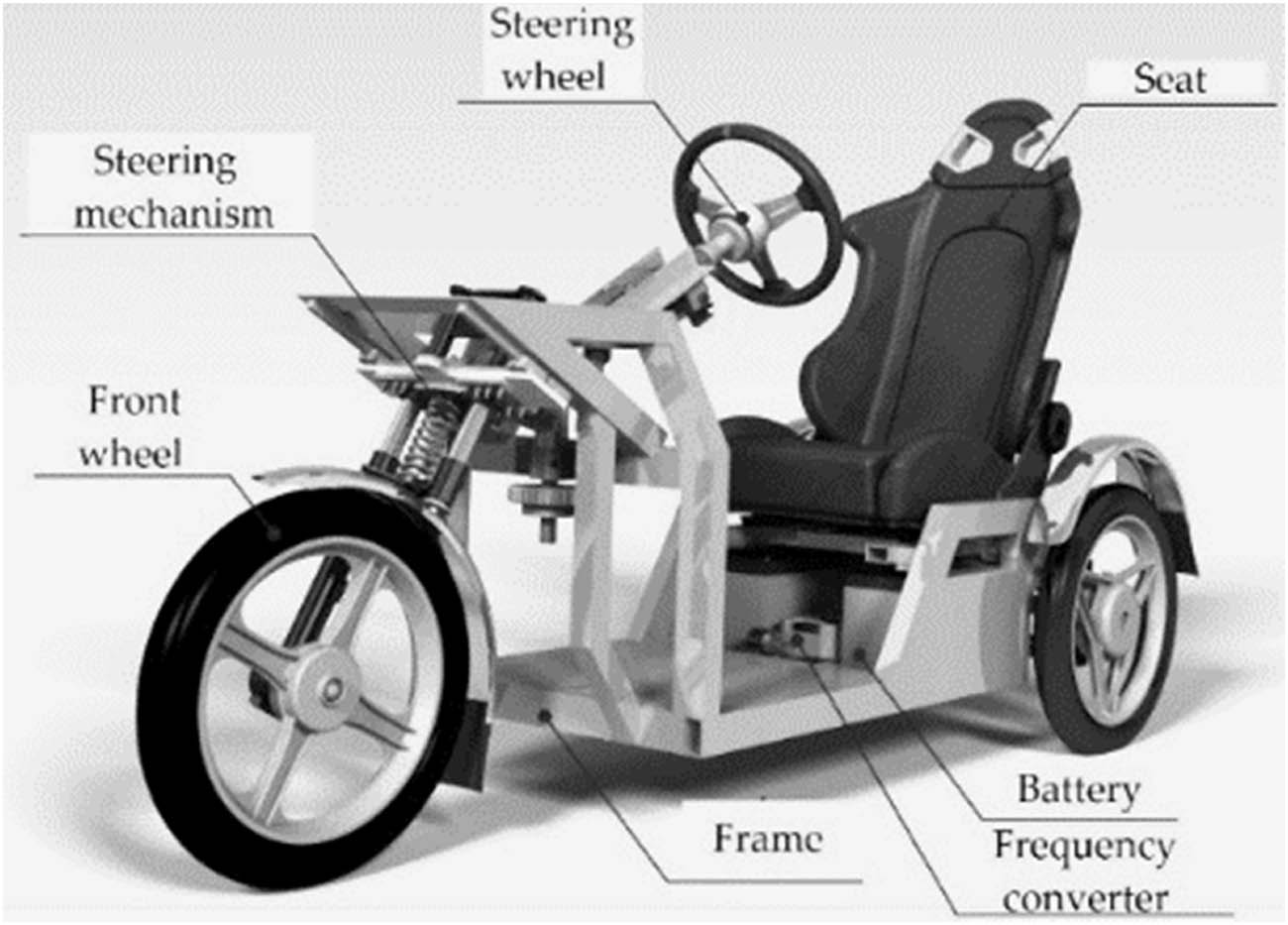
Current design of the three-wheeled electric vehicle.
Although such a vehicle is light in weight, its operation is limited by weather conditions. Therefore, the research team is continuing to work on the universal usage of the three-wheeled vehicle for any weather conditions, to improve its active and passive safety and its utility properties.
The goal of this work is to present the results of the research focused on changing the design of the tricycle and to present a comparison of the achieved dynamic properties of the original (a basic design) and modified tricycle (a modified design).
Section 2 contains theoretical background of the designs of the three-wheeled vehicles. A description of the modified design is given in Section 3, an analysis of overturning stability is included in Section 4 and an assessment of the vertical dynamics of the vehicles is provided in Section 5. Discussion is provided in Section 6 while conclusion of the research is given in Section 7.
2 Materials and methods
A tricycle is a three-wheeled vehicle, which is intended to transport people or material. This type of vehicle has certain advantages and disadvantages compared to the concept of two- and four-wheeled vehicles.
2.1 Basic types of three-wheeled vehicles
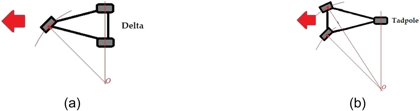
There are two types of three-wheeled vehicles (Figure 2): Delta version (Figure 2a), which has two rear wheels and one front wheel and Tadpole version (Figure 2b) with two front wheels and one rear wheel.
![Figure 2
Basic types of the three-wheeled vehicles: (a) Delta version and (b) Tadpole version [14].](/document/doi/10.1515/eng-2022-0441/asset/graphic/j_eng-2022-0441_fig_002.jpg)
Basic types of the three-wheeled vehicles: (a) Delta version and (b) Tadpole version [14].
The Tadpole type allows better stability in curves at higher speeds; however, it has usually larger turning radius, which is not so suitable for crowded cities. In both technical solutions, one wheel is placed in the axis of symmetry of the vehicle.
The Delta type brings better versatility and manoeuvrability, as the front wheel can rotate to larger angles in comparison with the Tadpole. Theoretically, this design allows us to reach a turning radius equal to the vehicle length; however, in practice, this is not possible to fulfil. The disadvantage of the Delta type is its lower stability during driving in curves (moreover, in combination with braking) [15,16,17].
The turning stability condition of the Delta type comes from Figure 3a and b, where F
O (m) is the centrifugal force and it represents a hypotenuse. Then, the force
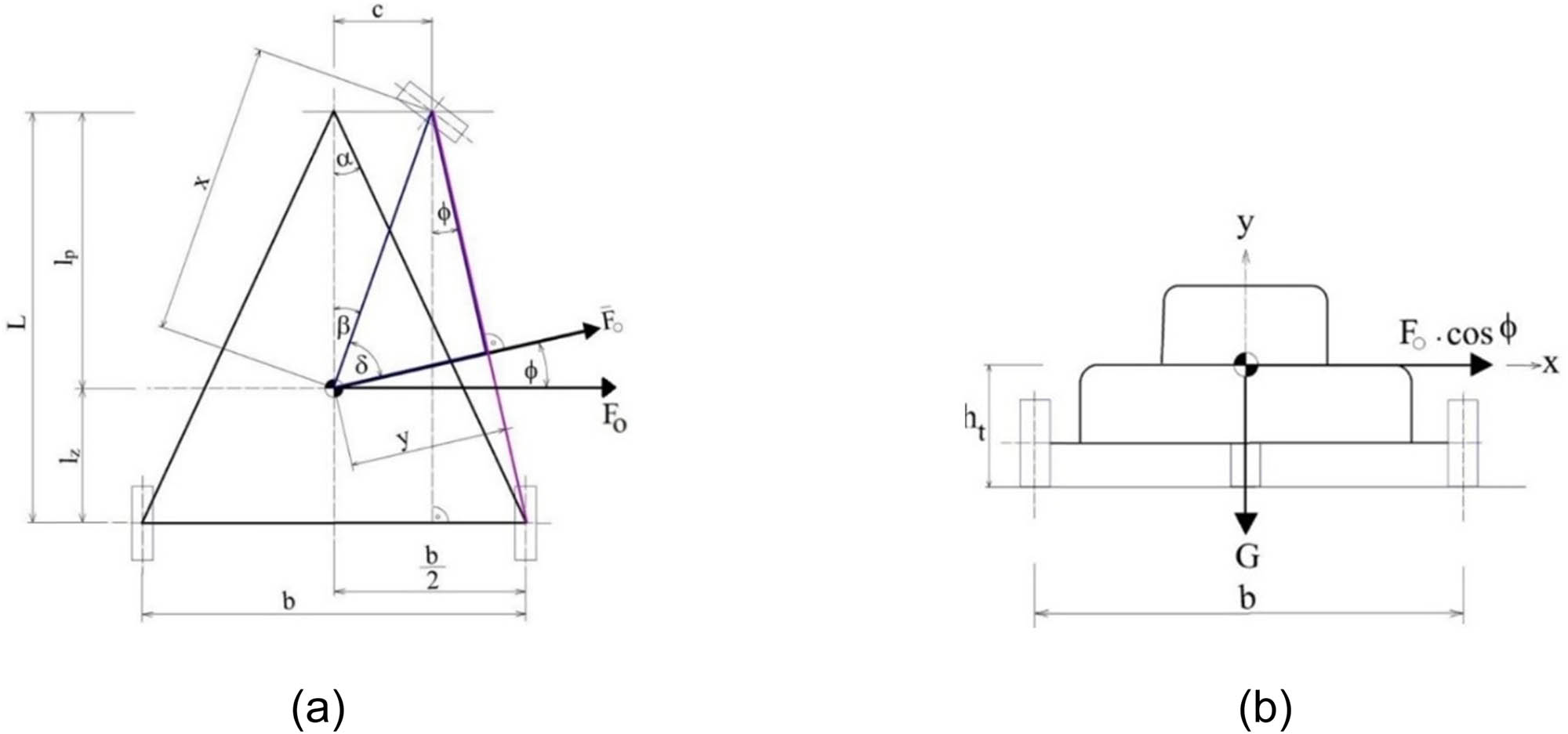
A modified design of the three-wheeled electric vehicle: (a) ground plan and (b) rear plan.
The centrifugal force of the vehicle is calculated based on the known formula.
where m (kg) is the weight of the vehicle, a O (m/s2) is the centripetal acceleration and G (N) is the gravitational force of the vehicle and it is calculated by the known formula as follows:
where g (m/s2) is the gravitational acceleration.
After substituting equations (2) and (3) in equation (1) and subsequent elimination of the vehicle weight m, the stability condition is as follows:
where a O (m/s2) is the centripetal acceleration, g (m/s2) is the gravitational acceleration, B (m) is the rear wheelbase, L (m) is the track width, l P (m) is the position of the centre of gravity from the front wheel and h (m) is the vertical position of the centre of gravity. These parameters are depicted in Figure 3.
Centripetal acceleration a O is calculated as follows:
where v (m/s) is the vehicle speed and R (m) is a curve radius.
The resulting condition for the limit speed of overturning stability of the Delta type is as follows:
where v max (m/s) is the maximal speed of the vehicle and R (m) is the curve radius. As it can be identified, the maximal speed in terms of the overturning stability of a Delta three-wheeled vehicle proportionally depends on the wheelbase B, the position of the centre of gravity l P, the curve radius R and disproportionally on the height of the centre of gravity h and the track width L. The weight of a vehicle is not critical, because it influences both gravitational force (the stability moment) and the centrifugal force (the tilting moment) equation (1).
2.2 Steering of three-wheeled vehicles
Obviously, the design of the front wheel is much simpler for the Delta type. The best is to choose a telescopic front fork. The rear axle is more complicated, because there are many types of wheel suspensions and it is necessary to investigate the best option for a particular vehicle.
The Tadpole design has the opposite situation. The rear wheel is usually suspended by a swinging arm and front wheels are suspended on a more complicated front axle. The Tadpole must include a steering mechanism and all needed components to reach an Ackermann steering geometry (Figure 4).
Ackermann steering geometry of two types of three-wheeled vehicles: (a) Delta version and (b) Tadpole version.
It follows that the Tadpole is more expensive type in terms of design and production and it is necessary to think about the requirements of the particular three-wheeled vehicle [12,13].
3 Modification of the tricycle
The modified design of the solved three-wheeled vehicle (Figure 5) comes from the original design of the vehicle (Figure 1). The main goal of the three-wheeled vehicle modification is to improve driving safety, driving comfort, protection against negative weather conditions as well as to improve the utility of the vehicle.
![Figure 5
A modified design of the three-wheeled electric vehicle: (a) front view and (b) rear view [18].](/document/doi/10.1515/eng-2022-0441/asset/graphic/j_eng-2022-0441_fig_005.jpg)
A modified design of the three-wheeled electric vehicle: (a) front view and (b) rear view [18].
3.1 Components of driving safety
A roof serves as the main safety element. It protects the driver against injury in case of overturning of the vehicle. It is composed of a frame, which is welded by means of hollow square profiles and thin metal sheets. A windscreen is also located on this frame and it protects passengers against wind and flying objects from the vehicle driving in front of it. The modified model is equipped with complex lighting technology, i.e. front lights, rear lights, a fog light and others (Figure 5). It is proposed to be made of LED technology to save electric energy and to warrant a life as long as possible.
Furthermore, the front part of the vehicle includes a covering of the special steering mechanism [19,20]. It will ensure a protection against dirt and it will significantly improve the passive safety of the vehicle in case of an accident (pedestrians, other vehicles, etc.) (Figure 6).
![Figure 6
A modified design of the three-wheeled electric vehicle: (a) front view and (b) rear view [18].](/document/doi/10.1515/eng-2022-0441/asset/graphic/j_eng-2022-0441_fig_006.jpg)
A modified design of the three-wheeled electric vehicle: (a) front view and (b) rear view [18].
3.2 Utility of the vehicle
The utility of the vehicle helps to improve a box mounted on the rear part of the vehicle on two holders. The box can serve as a luggage compartment, or it can be replaced by a bicycle carrier and others. The box is made of plastic material, which allows us to reduce the total weight at sufficient strength together with corrosion resistivity (Figure 5b).
The interior of the vehicle is equipped with a dashboard to display the required indicators, e.g. for lights, direction indicators, parameters of electrical powertrain and others. Further, it serves as a cover of a steering mechanism and it also actuates devices for lights, starting up, etc.
All these modifications of the vehicles have led mainly to change the total weight and position of the centre of gravity, which affect the dynamic properties of the vehicle. The position of the centre of gravity has been considered symmetrical to the longitudinal axis of the vehicle in both cases. Section 4 gives the results of simulation computations and comparison of the main parameters of the vehicle for the original design (Figure 1) and modified design (Figure 5).
To summarise, the description of the modified vehicle includes elements of active safety, which are mainly front and rear lights, indicators, mirrors, special steering mechanism for increasing overturning stability and others. The main element of passive safety is the frame, which prevents a passenger against injuries in case of an accident.
4 Simulation computations of driving overturing stability when driving in curves
Knowledge of theoretical parameters is necessary to compare the results of simulation computations. The theoretical parameters are obtained by means of analytical calculations. Calculations are performed for both original and modified designs of the three-wheeled vehicle and for various curve radii.
Basic parameters of the three-wheeled vehicle are listed in Table 1, where B (m) is the wheelbase, h (m) is the vertical position of the centre of gravity, L (m) is the track width, l P (m) is the position of the centre of gravity from the front wheel and g (m/s2) is the gravitational acceleration. The original design of the three-wheeled vehicle does not have a roof (Figure 1), while the modified design includes a roof (Figure 5).
Basic parameters of the three-wheeled vehicle
| Type of the vehicle | B (m) | h (m) | l P (m) | L (m) | g (m/s2) |
|---|---|---|---|---|---|
| Original design | 0.775 | 0.210 | 0.798 | 1.650 | 9.81 |
| Modified design | 0.775 | 0.470 | 0.855 | 1.650 | 9.81 |
Calculation of the maximal driving speed v max (m/s) for cornering is obtained by substituting parameters from Table 1 in the following formula:
The introduced calculation serves as an example and parameters are chosen for the original design of the vehicle and the curve radius R = 10 m. Maximal driving speeds have been calculated for the driving speed range from 0 to 100 km/h. Table 2 contains results for five selected curve radii.
Calculated maximal driving speeds during cornering for the original and modified vehicles
| R (m) | Original vehicle | Modified vehicle |
|---|---|---|
| v max (km/h) | v max (km/h) | |
| 10 | 33.68 | 23.31 |
| 25 | 53.26 | 36.85 |
| 50 | 75.32 | 52.11 |
| 75 | 92.25 | 63.83 |
| 100 | 106.52 | 73.70 |
These results indicate the stability of the vehicles for cornering. It can be understood from this kind of stability that a vehicle can drive through a curve at the maximal speed corresponding to the situation, when all wheels are still in contact with the road.
The position of the centre of gravity affects most significantly the stability for cornering. It is obvious from Figure 7 that the vertical position of the centre of gravity is higher for the modified vehicle (Figure 7b) in comparison to the original one (Figure 7a).
![Figure 7
Position of the centre of gravity: (a) the original design and (b) the modified design [18].](/document/doi/10.1515/eng-2022-0441/asset/graphic/j_eng-2022-0441_fig_007.jpg)
Position of the centre of gravity: (a) the original design and (b) the modified design [18].
These obtained results of analytical calculations have been compared with the results of the simulation computations performed in the Simpack software package. In principle, the results of simulation computations correspond to the results of analytical calculations. Slight differences are caused by the fact that simulation software better simulates a real situation, i.e. the centre of gravity moves during cornering in the direction of the vehicle movement. Tilting of the vehicle is not considered in analytical calculations. Therefore, the maximal driving speeds from simulation computations are little lower (Table 3).
Results of the contact of individual wheel and road surface with various surface qualities during driving for the original vehicle design
| Assessment of the tyre/road contact | ||||||
|---|---|---|---|---|---|---|
| Speed (km/h) | Wheel | Very good cement concrete | Good asphalt concrete | Good macadam | Medium pavement | Bad pavement |
| 10 | Front | ✓ | ✓ | ✓ | ✓ | ✓ |
| Rear right | ✓ | ✓ | ✓ | ✓ | ✓ | |
| Rear left | ✓ | ✓ | ✓ | ✓ | ✓ | |
| 20 | Front | ✓ | ✓ | ✓ | ✓ | ✓ |
| Rear right | ✓ | ✓ | ✓ | ✓ | ✗ | |
| Rear left | ✓ | ✓ | ✓ | ✓ | ✗ | |
| 30 | Front | ✓ | ✓ | ✓ | ✓ | ✗ |
| Rear right | ✗ | ✗ | ✗ | ✗ | ✗ | |
| Rear left | ✗ | ✗ | ✗ | ✗ | ✗ | |
Note: The road surface qualities and driving speeds are listed, wherein signs “✓” and “✗” in the columns indicate whether the individual wheel is still in contact with the roadway (“✓”) or it has lost contact (“✗”). Once any wheel has lost contact with the road surface during simulation, the driving is evaluated as unacceptable and the corresponding box is marked with the sign “✗.”.
The maximal driving speeds have been identified in the multibody simulation by evaluating the value of the vertical wheel force of the inner wheel during cornering (Note: an inner wheel during driving in a counter-clockwise curve is the left wheel, while an inner wheel during driving in a clockwise curve is the right wheel). The limit case is when the reaction between an inner wheel and the road equals to zero, i.e. the vertical reaction F R = 0 N.
Further, Figure 8 shows the waveforms of vertical wheel forces of the rear wheels of the original vehicle (left) and of the modified vehicle (right). This figure depicts how the vertical wheel forces are being changed during driving in curves with various radii. As it can be seen, the vertical wheel forces of the original vehicle are smaller due to lower total weight of the vehicle. Lower total weight is reflected by lower amplitudes of these forces in curves.
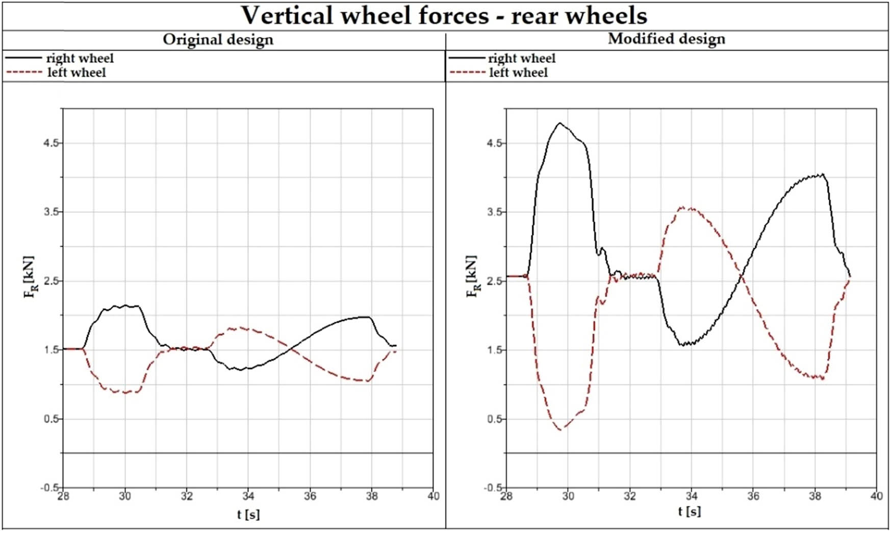
Waveforms of vertical wheel forces for rear wheels, the original design (left), the modified design (right).
On the other hand, the heavier vehicle has higher values of the vertical wheel forces as well as higher amplitudes of these forces in curves.
Figure 9 shows a comparison of additional kinematic parameters, the angle of tilting of the bodyworks of both the original and modified vehicle designs. As it can be recognised, the tilting of the bodywork of the modified vehicle is higher than the tilting of the original vehicle. Again, it is caused by the position of the centre of gravity, namely, its height. It also means that a passenger feels lower ride comfort level [20,21,22,23].
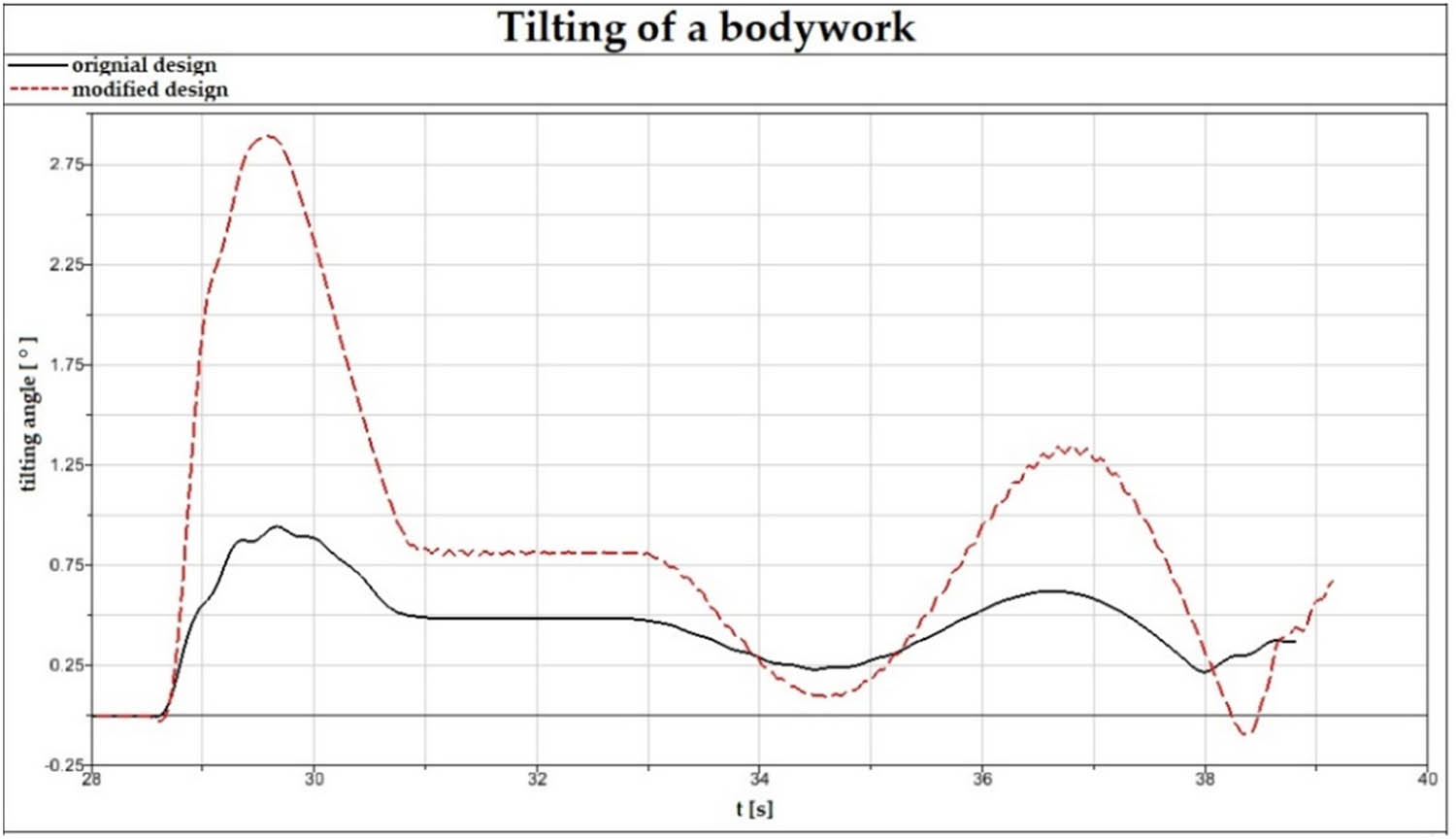
Waveforms of tilting angle of the bodywork, the original design (a black solid curve), the modified design (a red dash curve).
It can be concluded from the achieved results that modified vehicle can drive in curves at lower driving speeds than the original vehicle. The higher position of the centre of gravity leads to lower stability in curves.
5 Simulation computations of driving safety when driving on different road surfaces
From the driving safety point of view, the vertical force between the tyre and road surface is necessary to be investigated. When a vehicle is driven on a roadway with stochastic irregularities, the time response of the vertical loading of a wheel F W(t) is stochastic as well [23] (Figure 10).
![Figure 10
Response of the vertical load of a wheel with respect to time [23].](/document/doi/10.1515/eng-2022-0441/asset/graphic/j_eng-2022-0441_fig_010.jpg)
Response of the vertical load of a wheel with respect to time [23].
The force F
W varies about a certain average value
Then, the total vertical load of a wheel is given by the sum of the static vertical load of a wheel F Wstat (N) and the dynamic vertical loading of a wheel F Wdyn (N).
If equations (5) and (6) are considered, the variance in the vertical load of a wheel during the vehicle driving is defined as follows [23]:
The formulation (9) expresses the quadrate of the root means square of the vertical dynamic load of a wheel during driving on road irregularities. In the driving safety point of view, the standard deviation of the vertical dynamic load of a wheel σ Fdyn has to be as small as possible.
It is possible to determine the vertical static wheel force relatively easily, i.e. it is calculated from the total weight of the vehicle and the position of the centre of gravity in longitudinal and lateral directions. However, determining the vertical dynamic load of a wheel is more difficult. It is because the dynamic vertical load depends on vibrational properties of a vehicle, driving speed and roadway irregularities. These factors affect the total phenomenon called as the vertical dynamics of a vehicle. In terms of driving safety of a vehicle, reducing a wheel loading with respect to its static load is important. Smaller values of the vertical wheel force decrease the transmittable tangential forces, among which are the driving force, braking force and radial force, which are very important for steering of a vehicle. In limit cases, when a wheel jumps off the roadway, the vertical load of the wheel equals to zero (F Wdyn = 0 N). When this case appears on the steering axle, the vehicle is uncontrollable in this moment [24,25].
Simulation computations were performed for driving on a roadway with different surface qualities. Road surface irregularities have been modelled by means of the power spectral density (PSD). The PSD is a mathematical description of road surface irregularities and it allows us to input into a road surface model such data, which represent typical road surface qualities [26,27]. Hence, the mechanical system of the investigated vehicle is excited by the kinematic excitations.
In our research, a number of simulations have been performed for various types of road surface irregularities. As a representative example, results for five selected road surface irregularities are evaluated, in which, an adhesion coefficient f defined for individual road surfaces is indicated.
Very good cement concrete ( f = 0.75);
Good asphalt concrete ( f = 0.75);
Good macadam ( f = 0.65);
Medium pavement ( f = 0.65);
Bad pavement ( f = 0.65).
All road surfaces were supposedly dry. Driving safety of the investigated three-wheeled vehicle was assessed for several driving scenarios. The vehicle was tested with a variety of simulations and the vehicle was driven on the road with irregularities described above and at various speeds. The results presented below include only selected interesting results, namely, for the driving speed of 10, 20 and 30 km/h. In our tests, a straight track section has been chosen for avoiding negative effects to the monitored quantities, e.g. driving in curves, climbing, downhill, etc.
Table 3 shows the total overview of the results of simulation analyses for the original three-wheeled vehicle design. Results for the modified three-wheeled vehicle analysed in a similar manner are displayed in Table 4.
Results of the contact of individual wheel and road surface with various surface qualities during driving for the modified vehicle design
| Assessment of the tyre/road contact | ||||||
|---|---|---|---|---|---|---|
| Speed (km/h) | Wheel | Very good cement concrete | Good asphalt concrete | Good macadam | Medium pavement | Bad pavement |
| 10 | Front | ✓ | ✓ | ✓ | ✓ | ✓ |
| Rear right | ✓ | ✓ | ✓ | ✓ | ✓ | |
| Rear left | ✓ | ✓ | ✓ | ✓ | ✓ | |
| 20 | Front | ✓ | ✓ | ✓ | ✓ | ✓ |
| Rear right | ✓ | ✓ | ✓ | ✓ | ✓ | |
| Rear left | ✓ | ✓ | ✓ | ✓ | ✓ | |
| 30 | Front | ✓ | ✓ | ✓ | ✓ | ✗ |
| Rear right | ✓ | ✓ | ✓ | ✓ | ✗ | |
| Rear left | ✓ | ✓ | ✓ | ✗ | ✗ | |
Note: The road surface qualities and driving speeds are listed, wherein signs “✓” and “✗” in the columns indicate whether the individual wheel is still in contact with the roadway (“✓”) or it has lost contact (“✗”). Once any wheel has lost contact with the road surface during simulation, the driving is evaluated as unacceptable and the corresponding box is marked with the sign “✗.”.
The achieved results show that the original three-wheeled vehicle drive is still safe for speeds of 10 and 20 km/h (Table 3). All wheels were still in contact with the road and it does not depend on whether the three-wheeled vehicle is driven on very good quality road or a road with medium pavement surface quality. Once the original vehicle is driven at the speed of 30 km/h, the driving is not safe either for low road quality or for very good road quality. Despite the front wheel of the vehicle being in contact with the road for four out of five road qualities, the other wheels jumped off the road, therefore, the driving must not be evaluated as safe.
On the other hand, the driving of the modified three-wheeled vehicle seems to be safer for investigated driving conditions (Table 4). All wheels are in contact with the road for speeds of 10, 20 km/h as well as 30 km/h for very good cement concrete, good asphalt concrete and good macadam. Driving on the medium pavement represents not completely safe driving, because the rear left wheel jumped off the road. Despite the centre of gravity being located in the longitudinal plane of the symmetry, rear right wheel is still in contact with the road. However, driving the modified vehicle on the bad pavement quality at the speed of 30 km/h is not safe.
As it can be seen from the presented results in terms of vertical dynamics, higher total weight of the vehicle has led to better driving safety with regards to driving on the road with irregularities. The modified vehicle has higher total weight, but the stiffness-damping parameters of the suspension system correspond to the original one.
6 Discussion
Achieved results of simulation computations for defined driving conditions have revealed important findings.
In terms of overturning stability of the vehicle during cornering, the original design of the vehicle with lower position of the centre of gravity is more appropriate and this type of vehicle is able to overcome curves at higher driving speeds. On the other hand, the modified vehicle (with a roof and additional accessories) has higher total weight, which contributes to decreased vertical vibrations of the vehicle during driving on a rough road, mainly at higher driving speeds.
The driving speeds of both vehicles (original and modified) for analysis of overturing stability have been chosen much higher than the driving speeds were for analysis of the driving safety on various road surfaces. The achieved results lead to the motivation to perform further research activities with the vehicle, such as additional modification and investigation of the vehicle. All activities should lead to optimal technical solutions, which will make use of favourable parameters of the vehicle, such as the position of the centre of gravity, wheelbase, track width and others for safe driving in curves. The vertical dynamics of the vehicle is affected mainly by the parameters of the used springs and dampers. These components should be modified to achieve the acceptable vibrational properties for driving on various road surface qualities, which can occur in urban environment.
7 Conclusion
Using small urban vehicles with an electric powertrain will be still up to date. They provide relatively rational solution not only for overcrowded agglomerations, but also for smaller cities, which want to retain a clean environment. The presented three-wheeled vehicle is one of the transport means. As the vehicle is just a prototype, it is necessary to investigate its driving properties. The presented research provided the view for development process. The original vehicle was modified to improve its utility for universal operation. The performed simulation calculations revealed that the overturning stability of the original vehicle is more favourable in comparison to the heavier modified design. In contrast, the higher total weight of the vehicle has certain advantages with respect to the vertical dynamics.
-
Funding information: This publication was realised with support of Operational Program Integrated Infrastructure 2014–2020 of the project: Innovative Solutions for Propulsion, Power and Safety Components of Transport Vehicles, code ITMS 313011V334, co-financed by the European Regional Development Fund.
-
Author contributions: Miroslav Blatnický: conceptualisation, validation, investigation and writing – original manuscript; Ján Dižo: conceptualisation, methodology, software, formal analysis, investigation, resources, data curation, writing – original manuscript, visualisation and funding acquisition; Andrej Suchánek: software, formal analysis, writing – review and editing; Pavol Šťastniak: conceptualisation, software, data curation, visualisation and writing – review and editing.
-
Conflict of interest: Authors state no conflict of interest.
-
Data availability statement: Not applicable.
References
[1] Droździel P, Wrona R. Legal and utility problems of accidents on express roads and motorways. Proceedings of the 11th International Science and Technical Conference Automotive Safety. Casta Papiernicka, Slovakia; 2018.10.1109/AUTOSAFE.2018.8373315Search in Google Scholar
[2] Caban J, Droździel P. Traffic congestion in chosen cities of Poland. Sci J Silesian Univ Technol. Series Transport. 2020;18:5–14.10.20858/sjsutst.2020.108.1Search in Google Scholar
[3] Montero L, Linares MP, Serch O. A visualization tool based on traffic simulation for the analysis and evaluation of smart city policies, innovative vehicles and mobility concepts. Proceedings of the Winter Simulation Conference 2017, December 3–6. Las Vegas, USA; 2017.10.1109/WSC.2017.8248038Search in Google Scholar
[4] Ewert A, Brost M, Eisenmann C, Stieler S. Small and light electric vehicles: An analysis of feasible transport impacts and opportunities for improved urban land use. Sustainability. 2020;12:17.10.3390/su12198098Search in Google Scholar
[5] Vázquez-Rodríguez EA, Perez-Pinal FJ, Rodríguez-Licea MA. The rollover risk and its mitigation in rickshaws. Proceedings of the IEEE International Autumn Meeting on Power, Electronics and Computing (ROPEC 2018). Ixtapa, Guerrero; 2018.10.1109/ROPEC.2018.8661423Search in Google Scholar
[6] Wilhelm T, Dorsch V, Gauterin F. Mass data measurement, approximation and influence on vehicle stability for ultra-light human-powered vehicles. Appl Sci. 2021;11:20.10.3390/app11125485Search in Google Scholar
[7] Edelmann J, Plöchl M, Lunger P. Modelling and analysis of the dynamics of a tilting three-wheeled vehicle. Multibody Syst Dyn. 2011;26:469–87.10.1007/s11044-011-9258-7Search in Google Scholar
[8] Esmaeili S, Al-Khaldi M, Al-Shammari S, Darweesh F, Al-Mannaei T, Imdoukh A. Design, analysis, and mechanical assembly of a three-wheeled solar-powered electric vehicle. Int J Comput Digital Syst. 2020;9:515–22.10.12785/ijcds/090315Search in Google Scholar
[9] Margetts R, Margolis D. Modeling a Battery-Electric Three-Wheeled Car Concept. SAE Technical Papers 2020; 2020.10.4271/2020-01-5052Search in Google Scholar
[10] Kostrzewski M. One design issue – many solutions. Different perspectives of design thinking – case study. Commun Comput Inf Sci. 2018;877:179–90.10.1007/978-3-319-95204-8_16Search in Google Scholar
[11] Brumercik F, Lukac M, Caban J. Unconventional powertrain simulation. Commun – Sci Lett Univ Zilina. 2016;18:30–3.10.26552/com.C.2016.2.30-33Search in Google Scholar
[12] Dizo J, Barta D, Blatnicky M. Improvement driving characteristics of electric tricycle. Proceedings of the 17th International Scientific Conference Engineering for Rural Development ERD 2018, May 23-25. Jelgava, Latvia; 2018.10.22616/ERDev2018.17.N473Search in Google Scholar
[13] Pavlik A, Dizo J, Kurcik P, Blatnicky M, Strazovec P. Increase of the overturning immunity of an electric tricycle. Manuf Technol. 2019;19:297–302.10.21062/ujep/286.2019/a/1213-2489/MT/19/2/297Search in Google Scholar
[14] Quora. https://www.quora.com/What-are-the-advantages-to-having-two-wheels-at-the-front-instead-of-the-back-on-a-three-wheeled-vehicle (accessed on 13-12-2022).Search in Google Scholar
[15] Muiz MA, Jati MK, Cahyono FP, Sumarsono DA. Static simulation of electric tilting tricycle frame structure using the finite element analysis. Proceedings of the 2nd International Conference on Mechanical Manufacturing and Industrial Engineering MMIE 2019, December 14–16. Beijing, China; 2019.Search in Google Scholar
[16] Syehan A, Pamungkas AT, Sumarsono DA. Static simulation of E-bike tilting three-wheeled frame structure using the finite element method. Proceedings of the International Conference on Me-chanical Engineering Research and Application 2018, October 23–25. Malang, Indonesia; 2018.Search in Google Scholar
[17] Bucchi F, Cerù F, Frendo F. Stability analysis of a novel four-wheeled motorcycle in straight running. Meccanica. 2017;52:2603–13.10.1007/s11012-017-0645-xSearch in Google Scholar
[18] Misak P. Creation of a computational model and analysis of driving properties of an E-3kolka. Bachelor thesis. Žilina, Slovak Republic: University of Žiline; 2021.Search in Google Scholar
[19] Dižo J, Blatnický M. Analysis of ride comfort of a three-wheeled vehicle. Proceedings of the 16th International Conference Dynamics of Rigid and Deformable Bodies. Ústí nad Labem, Czech Republic; 2018.Search in Google Scholar
[20] Dižo J, Blatnický M, Melnik R. Assessment of passengers ride comfort of a tricycle. LOGI – Sci J Transp Logist. 2018;9:10–7.10.2478/logi-2018-0014Search in Google Scholar
[21] Gerlici J, Lack T, Ondrova Z. Evaluation of comfort for passenger of railway vehicles. Komunikacie. 2007;9:44–9.10.26552/com.C.2007.4.44-49Search in Google Scholar
[22] Lack T, Gerlici J. Analysis of vehicles dynamic properties from: The point of view of passenger comfort. Komunikacie. 2008;10:10–8.10.26552/com.C.2008.3.10-18Search in Google Scholar
[23] Vlk F. Dynamics of engine vehicles (In Czech). 1st edn. Brno, Czech Republic; 2008.Search in Google Scholar
[24] Weyssenhoff A, Opala M, Koziak S, Melnik R. Characteristics and investigation of selected manufacturing defects of passenger car tires. Proceedings of the 13th International Scientific Conference on Sustainable, Modern and Safe Transport TRANSCOM 2019, May 29–31. Novy Smokovec, Slovakia; 2019.Search in Google Scholar
[25] Kováč M, Decký M, Leitner B. The objectification of road unevenness evaluation by the use of vehicle-pavement interaction simulation. Proceedings of the 20th International Scientific Conference on Transport Means 2016. Juodkrante, Lithuania; 2016.Search in Google Scholar
[26] Klimenda F, Soukup J, Skočilasová B, Skočilas J. Vertical vibration of the vehicle when crossing over transverse speed bumps. Manuf Technol. 2020;20:55–9.10.21062/mft.2020.020Search in Google Scholar
[27] Klimenda F, Svoboda M, Rychlikova L, Petrenko A. Investigation of vertical vibration of a vehicle model driving through a horizontal curve. Manuf Technol. 2015;15:143–8.10.21062/ujep/x.2015/a/1213-2489/MT/15/2/143Search in Google Scholar
© 2023 the author(s), published by De Gruyter
This work is licensed under the Creative Commons Attribution 4.0 International License.
Articles in the same Issue
- Regular Articles
- Design optimization of a 4-bar exoskeleton with natural trajectories using unique gait-based synthesis approach
- Technical review of supervised machine learning studies and potential implementation to identify herbal plant dataset
- Effect of ECAP die angle and route type on the experimental evolution, crystallographic texture, and mechanical properties of pure magnesium
- Design and characteristics of two-dimensional piezoelectric nanogenerators
- Hybrid and cognitive digital twins for the process industry
- Discharge predicted in compound channels using adaptive neuro-fuzzy inference system (ANFIS)
- Human factors in aviation: Fatigue management in ramp workers
- LLDPE matrix with LDPE and UV stabilizer additive to evaluate the interface adhesion impact on the thermal and mechanical degradation
- Dislocated time sequences – deep neural network for broken bearing diagnosis
- Estimation method of corrosion current density of RC elements
- A computational iterative design method for bend-twist deformation in composite ship propeller blades for thrusters
- Compressive forces influence on the vibrations of double beams
- Research on dynamical properties of a three-wheeled electric vehicle from the point of view of driving safety
- Risk management based on the best value approach and its application in conditions of the Czech Republic
- Effect of openings on simply supported reinforced concrete skew slabs using finite element method
- Experimental and simulation study on a rooftop vertical-axis wind turbine
- Rehabilitation of overload-damaged reinforced concrete columns using ultra-high-performance fiber-reinforced concrete
- Performance of a horizontal well in a bounded anisotropic reservoir: Part II: Performance analysis of well length and reservoir geometry
- Effect of chloride concentration on the corrosion resistance of pure Zn metal in a 0.0626 M H2SO4 solution
- Numerical and experimental analysis of the heat transfer process in a railway disc brake tested on a dynamometer stand
- Design parameters and mechanical efficiency of jet wind turbine under high wind speed conditions
- Architectural modeling of data warehouse and analytic business intelligence for Bedstead manufacturers
- Influence of nano chromium addition on the corrosion and erosion–corrosion behavior of cupronickel 70/30 alloy in seawater
- Evaluating hydraulic parameters in clays based on in situ tests
- Optimization of railway entry and exit transition curves
- Daily load curve prediction for Jordan based on statistical techniques
- Review Articles
- A review of rutting in asphalt concrete pavement
- Powered education based on Metaverse: Pre- and post-COVID comprehensive review
- A review of safety test methods for new car assessment program in Southeast Asian countries
- Communication
- StarCrete: A starch-based biocomposite for off-world construction
- Special Issue: Transport 2022 - Part I
- Analysis and assessment of the human factor as a cause of occurrence of selected railway accidents and incidents
- Testing the way of driving a vehicle in real road conditions
- Research of dynamic phenomena in a model engine stand
- Testing the relationship between the technical condition of motorcycle shock absorbers determined on the diagnostic line and their characteristics
- Retrospective analysis of the data concerning inspections of vehicles with adaptive devices
- Analysis of the operating parameters of electric, hybrid, and conventional vehicles on different types of roads
- Special Issue: 49th KKBN - Part II
- Influence of a thin dielectric layer on resonance frequencies of square SRR metasurface operating in THz band
- Influence of the presence of a nitrided layer on changes in the ultrasonic wave parameters
- Special Issue: ICRTEEC - 2021 - Part III
- Reverse droop control strategy with virtual resistance for low-voltage microgrid with multiple distributed generation sources
- Special Issue: AESMT-2 - Part II
- Waste ceramic as partial replacement for sand in integral waterproof concrete: The durability against sulfate attack of certain properties
- Assessment of Manning coefficient for Dujila Canal, Wasit/-Iraq
- Special Issue: AESMT-3 - Part I
- Modulation and performance of synchronous demodulation for speech signal detection and dialect intelligibility
- Seismic evaluation cylindrical concrete shells
- Investigating the role of different stabilizers of PVCs by using a torque rheometer
- Investigation of high-turbidity tap water problem in Najaf governorate/middle of Iraq
- Experimental and numerical evaluation of tire rubber powder effectiveness for reducing seepage rate in earth dams
- Enhancement of air conditioning system using direct evaporative cooling: Experimental and theoretical investigation
- Assessment for behavior of axially loaded reinforced concrete columns strengthened by different patterns of steel-framed jacket
- Novel graph for an appropriate cross section and length for cantilever RC beams
- Discharge coefficient and energy dissipation on stepped weir
- Numerical study of the fluid flow and heat transfer in a finned heat sink using Ansys Icepak
- Integration of numerical models to simulate 2D hydrodynamic/water quality model of contaminant concentration in Shatt Al-Arab River with WRDB calibration tools
- Study of the behavior of reactive powder concrete RC deep beams by strengthening shear using near-surface mounted CFRP bars
- The nonlinear analysis of reactive powder concrete effectiveness in shear for reinforced concrete deep beams
- Activated carbon from sugarcane as an efficient adsorbent for phenol from petroleum refinery wastewater: Equilibrium, kinetic, and thermodynamic study
- Structural behavior of concrete filled double-skin PVC tubular columns confined by plain PVC sockets
- Probabilistic derivation of droplet velocity using quadrature method of moments
- A study of characteristics of man-made lightweight aggregate and lightweight concrete made from expanded polystyrene (eps) and cement mortar
- Effect of waste materials on soil properties
- Experimental investigation of electrode wear assessment in the EDM process using image processing technique
- Punching shear of reinforced concrete slabs bonded with reactive powder after exposure to fire
- Deep learning model for intrusion detection system utilizing convolution neural network
- Improvement of CBR of gypsum subgrade soil by cement kiln dust and granulated blast-furnace slag
- Investigation of effect lengths and angles of the control devices below the hydraulic structure
- Finite element analysis for built-up steel beam with extended plate connected by bolts
- Finite element analysis and retrofit of the existing reinforced concrete columns in Iraqi schools by using CFRP as confining technique
- Performing laboratory study of the behavior of reactive powder concrete on the shear of RC deep beams by the drilling core test
- Special Issue: AESMT-4 - Part I
- Depletion zones of groundwater resources in the Southwest Desert of Iraq
- A case study of T-beams with hybrid section shear characteristics of reactive powder concrete
- Feasibility studies and their effects on the success or failure of investment projects. “Najaf governorate as a model”
- Optimizing and coordinating the location of raw material suitable for cement manufacturing in Wasit Governorate, Iraq
- Effect of the 40-PPI copper foam layer height on the solar cooker performance
- Identification and investigation of corrosion behavior of electroless composite coating on steel substrate
- Improvement in the California bearing ratio of subbase soil by recycled asphalt pavement and cement
- Some properties of thermal insulating cement mortar using Ponza aggregate
- Assessment of the impacts of land use/land cover change on water resources in the Diyala River, Iraq
- Effect of varied waste concrete ratios on the mechanical properties of polymer concrete
- Effect of adverse slope on performance of USBR II stilling basin
- Shear capacity of reinforced concrete beams with recycled steel fibers
- Extracting oil from oil shale using internal distillation (in situ retorting)
- Influence of recycling waste hardened mortar and ceramic rubbish on the properties of flowable fill material
- Rehabilitation of reinforced concrete deep beams by near-surface-mounted steel reinforcement
- Impact of waste materials (glass powder and silica fume) on features of high-strength concrete
- Studying pandemic effects and mitigation measures on management of construction projects: Najaf City as a case study
- Design and implementation of a frequency reconfigurable antenna using PIN switch for sub-6 GHz applications
- Average monthly recharge, surface runoff, and actual evapotranspiration estimation using WetSpass-M model in Low Folded Zone, Iraq
- Simple function to find base pressure under triangular and trapezoidal footing with two eccentric loads
- Assessment of ALINEA method performance at different loop detector locations using field data and micro-simulation modeling via AIMSUN
- Special Issue: AESMT-5 - Part I
- Experimental and theoretical investigation of the structural behavior of reinforced glulam wooden members by NSM steel bars and shear reinforcement CFRP sheet
- Improving the fatigue life of composite by using multiwall carbon nanotubes
- A comparative study to solve fractional initial value problems in discrete domain
- Assessing strength properties of stabilized soils using dynamic cone penetrometer test
- Investigating traffic characteristics for merging sections in Iraq
- Enhancement of flexural behavior of hybrid flat slab by using SIFCON
- The main impacts of a managed aquifer recharge using AHP-weighted overlay analysis based on GIS in the eastern Wasit province, Iraq