Experimental and theoretical investigation of the structural behavior of reinforced glulam wooden members by NSM steel bars and shear reinforcement CFRP sheet
-
Hayder H. Alkhudery
 ,
Haider Ali Al-Tameemi
,
Haider Ali Al-Tameemi

Abstract
Reinforcing the wooden structural members is considered as a challenging matter to overcome the drawbacks of using wood in the construction field. The current investigation, therefore, presents an attempt to evaluate the effectiveness of utilizing steel bars as reinforcements in glulam timber beams using the near-surface-mounted (NSM) technique in conjunction with carbon fiber-reinforced polymer (CFRP) sheet wraps. A series of flexural testing was carried out until failure for both reinforced and unreinforced glulam members in a simple support system. Eleven specimens were examined in two groups to compare them with the control beam. Five reinforced glulam (RG) beams of the first group were reinforced with different schemes at tension and compression zones using the same bar size. The other five specimens of the second group were reinforced with shear reinforcement using fully wrapped strips made of CFRP sheet in addition to the same flexural reinforcement schemes as the first group. Each glulam beam has a span of 1.35 m and a rectangular section sized 85 mm × 175 mm. Based on experimental outcomes, theoretic modeling was provided to estimate the ultimate load capacity and bending rigidity of reinforcing glulam members. Though several theoretical predictions of flexural capacity were overstated when compared to experimental predictions, these disparities were frequently about 10%, confirming that the proposed theoretical model was accurate, and the mean of ultimate loading capacity and deflection between experimental and theoretical results were 1.01 and 1.09, respectively. Experimental results presented show that the RG beams performed much better than the unreinforced reference beams in terms of structural behavior, with improvements in ultimate load capacity ranging from 16 to 49%. On the other hand, the shear reinforcement for RG members slightly improved flexural performance, and the ultimate load capacity increased by 2–7%. Therefore, it was concluded that the NSM techniques using ordinary steel bars were effective ways in strengthening the glulam members in terms of flexural stiffness with increasing ultimate load capacity.
1 Introduction
Timber is an attractive and appealing building material. Some of the economic advantages of wood are its availability, cost, and ease of fabrication. Today, structural timber elements can be constructed with a wide range of sizes and shapes. However, unlike other engineering materials, timbers are of organic origin and anisotropic; their strength and mechanical characteristics vary considerably. Thus, extensive experimental research is required to achieve the demand for timber building [1,2,3].
Concrete and steel are artificial materials developed for specific activities; thus, they are less likely to contain defects similar to those caused by a natural result in timber. Glulam, or glued layered timber, is a form of engineering wood used in construction for well over a decade. Engineering wood can be constructed from wood panels, typically 19–50 mm thickness and 1.5–5 m length. The panels are indexed by strength and bonded together with high-strength adhesive by pressure, with wood grains aligned to the span length. Fracture typically occurs at the weak point, frequently where knots or cracks exist. Natural imperfections in the timber are dispersed more consistently throughout the section of glulam components, resulting in higher glulam element strength. As a result, glulam products are stiffer and more rigid than typical lumber products, as shown in Figure 1. As can be observed, glulam has a greater average strength (f m); in addition, the characteristic strength (f k) increases and the variance decreases [4,5].
![Figure 1
Strength of standard timber vs glulam [2].](/document/doi/10.1515/eng-2022-0481/asset/graphic/j_eng-2022-0481_fig_001.jpg)
Strength of standard timber vs glulam [2].
Although glulam is widely used and internationally known, it still requires strengthening owing to the natural weakness of its main wood component. External and internal bonding techniques are primarily utilized in timber reinforcements. Steel and FRP sheets are used in the tension area of a structural element when externally bonded reinforcements (EBR) are achieved. Bonded fractures within the concrete and externally reinforced steel or FRP elements conduct structural strengthening with the EBR technique when the plates or reinforcement bars are exposed to damage by vehicular traffic or fire [6,7,8]. For internal bonding systems, reinforcing bars are often fastened into grooves or slots of timber, which refers to near-surface mounted (NSM). Bond and load capacity are improved with NSM over EBR due to anchoring the bars into surrounding host members and a better bond connection between the host core elements and the adherence; also, the host wood protects the reinforcement materials [9,10,11].
Recently, the NSM method for reinforcing timber construction has been widely used, and studies have confirmed its application [12]. Based on investigations into the use of NSM strengthening, it involves enhancements in stiffness and bending strength of timber members [13,14,15]. Studies of long-term bending strength have also demonstrated the NSM technique’s effectiveness [16]. Some of these previous studies, with their contribution and main outcomes, are illustrated in detail subsequently.
Gentile et al. studied wooden solid beams reinforced with GFRP bars using the NSM technique. They indicated that the enhancement of the flexural beam strength in a range of 18–46% with the strengthening ratios were 0.27–0.82% in comparison with unreinforced members [14].
Johnsson et al. investigated glulam timber members reinforced by carbon fiber-reinforced polymer (CFRP) rods between the glulam lamellas. They indicated that NSM reinforcing technique enhanced the ultimate moment capacity by about 49–63% [5].
Raftery and Harte developed a finite element modeling of the nonlinear response of glulam members reinforced by GFRP bars, and this model was accurate in comparison with previous experimental results [15].
Raftery and Kelly explored the bending behavior of glulam timber members stiffened and repaired by basalt FRP bars in tension face only. They used the NSM technique with two arrangement locations of reinforcement; one located in a groove at the bottom face of the member and the other placed into a groove at the sides of the member. The average enhancement of ultimate capacity was 23%, and the structural stiffness was improved in the range of 8.4–10.3% [16].
Yang et al. explored the flexural behavior of glulam members reinforced using steel and FRP of bars and plates. They evaluated a significant improvement in flexural capacity and structural stiffness up to 56.3 and 27.5% on average, respectively. In addition, they introduced a theoretical model based on experimental results with acceptable accuracy [17].
Bakalarz et al. examined the bending characteristics of reinforced glued lumber beams by CFRP strips fixed into grooves by epoxy resin at the bottom face. They indicated that the reinforcements enhanced the flexural capacity by up to 32% on average in comparison with the control beam. Also, the modulus of elasticity increased by about 11% in bending and stiffness coefficients [18,19].
Yeboah and Gkantou used the NSM technology with reinforcements of glass and basalt FRP rods to increase the bending performance of glulam timber members. They used two reinforcement configurations: one reinforcement was located at the bottom beam face and the other was on both faces. They observed that the main failure in both reinforced and unreinforced members was the brittle tension mechanism. Furthermore, the NSM reinforcement increased the flexural stiffness (22–33%), while (33–69%) increasing the ultimate strength of the glulam timber members [4].
One of the significant challenges in the construction of timber buildings is determining the ultimate capacity. The current flexural strength calculation method is derived from elastic beam theory, which is insufficient in several aspects concerning the experimentation results of glued timber members, which are indicated as a high safety factor in the elastic method. It is essential to adopt a basic understanding theory for the structural performance of glulam members with the increase in building material cost, which is leading to the more cost-effective use of wood.
Therefore, the basic objective of the present study was to establish a proposed theoretical model of structural analysis and evaluate the efficiency of using the NSM procedure as a strengthening method to timber structures for the enhancement of the overall mechanical performance. Also, an experimental program was achieved for glulam cases under consideration utilizing various cross-sectional reinforcing schemes and ratios.
2 Experiment works
In the experimental part of this study, 11 specimens were examined in 2 groups to compare them with the control beam. Five reinforced glulam (RG) beams of the first group were reinforced with different schemes at tension and compression zones using the same bar size. While the other five specimens of the second group were reinforced with shear reinforcement using fully wrapping strips made of CFRP sheet in addition to the same flexural reinforcement schemes as the first group.
2.1 Material characteristics
For the experimental works in this study, the material used was illustrated as follows:
Glulam timber: all 11 timber beams with a final dimension of 85 mm × 175 mm × 1,500 mm are made from the same timber panels 90 mm × 50 mm × 1,500 mm, which are fabricated by UGRA company of timber from the Tyumen region, Russia. Table 1 presents the main mechanical characteristic values as specified by the supplier.
Reinforcement bar: the steel deformed bars had a diameter of 10 mm inserted as reinforcement at the tension and/or compression zones of timber beams. The main mechanical properties of the steel bars were 200 GPa for the modulus of elasticity and 400 MPa for yield strength, and these values were specified by the supplier.
Sheet of carbon fiber: the CFRP sheet used for the wrapping of glulam beam, which was the Sika-Wrap®-300C model made by Sika Company. Table 2 presents characteristics and properties as specified by the supplier.
Adhesions: the resin of reinforced bars into a groove of glulam beams was Sika-dur®-330, which is an epoxy resin two-component model shown in Table 3, which was specified by the supplier, while the phenol resorcinol formaldehyde was used as adhesives between interlock faces of timber panels, which constituted a glulam beam.
Timber mechanical characteristics
| Types | Grais direction | Values (MPa) |
|---|---|---|
| Flexural | Edgewise along the grain | 32 |
| Flatwise along the grain | 33 | |
| Compression | Edgewise along the grain | 35 |
| Across the grain | 4 | |
| Tension | Edgewise along the grain | 32 |
| E-glulam | Along the grain | 8,500 |
| G-glulam | Across the grain | 500 |
Fiber properties
| Model | Fiber type | Appearance | Thickness (mm) | Area density (g/m2) | Tensile strength (MPa) | E in-tension (GPa) | Elongation at break |
|---|---|---|---|---|---|---|---|
| Sika-Wrap®-300C | High strength carbon | Unidirectional | 0.167 | 304 | 4,000 | 230 | 1.7% |
Epoxy resin properties
| Model | Density (kg/l) | Tensile strength | E tension (MPa) | E flexural (MPa) | Elongation at break |
|---|---|---|---|---|---|
| Sika-dur®-330 | 1.31 | 30 | 4,500 | 3,800 | 0.9% |
2.2 Specimen fabrication
Each of the 11 glulam timber members tested in this study was fabricated as shown in Figure 2. The steps of the fabrication process can be described as follows:
Rendering timber panels from factory production size to dimensions 85 mm × 44 mm × 1,500 mm.
Glued each of four timber panels to produce one glulam beam by adhesive under pressure for 72 h.
Rendering glulam beams to dimensions 85 mm × 175 mm × 1,500 mm.
Cutting the longitudinal groove with sectional dimensions of 15 mm × 15 mm at the corresponding location for the specimen.
Cleaning longitudinal grooves and reinforcement bars with high air pressure before placing the steel bar in the groove after epoxy resin insertion; in the specimen of reinforcement in tension and compression zone, the bars of tension face were inserted, and after 24 h bars of compression face were inserted.
Samples, the bars were first placed on the tensile zone, and 24 h later, the bar on the compression zone was inserted.
Curing time of the RG beam was 7 days prior testing according to the data sheet of the supplier of the epoxy resin of Sika-dur®-330.
Wrapping CFRP sheets around glulam beams with epoxy resin if needed concerning specimen cases.

Fabrication processes of glulam member.
2.3 Specimen configurations
A total of 11 glued-laminated beam samples (Figures 3 and 4, and Table 4), one unreinforced (control), group 1 consisted of five RG beams with steel bars, and group 2 consisted of five beams reinforced by steel bars with wrapping by CFRP sheet. All beams were tested according to BS EN 408:2010 with a bending configuration test (i.e., four points load) under static loading. Each sample was 1.5 m long and rectangular cross-section of 85 mm × 175 mm. The NSM technique was used to reinforce glulam beams at corresponding zones (i.e., tension and/or compression zone; Figure 4). Each glulam beam has a span of 1.35 m, which was divided equally to three-thirds of 450 mm in a typical four-point loading system. Therefore, the ratio of shear span to total depth was equal to 2.5. The available wood in the local construction market governed the selection of this dimension. The top steel bars were used in some cases of the tested timber beams to reinforce the timber beam against compressive stresses that develop in the upper side of the beam due to the bending moment because there is no large difference between the compressive and tensile strengths of the timber. In addition, Figure 5 shows a wrapping CFRP sheet reinforcement for the beams of group 2 only. The wrapping reinforcement was 40 × 600 CFRP sheet @150 mm, which was constant for all beams and distributed at the shear force region only along the beam.

Specimen details.
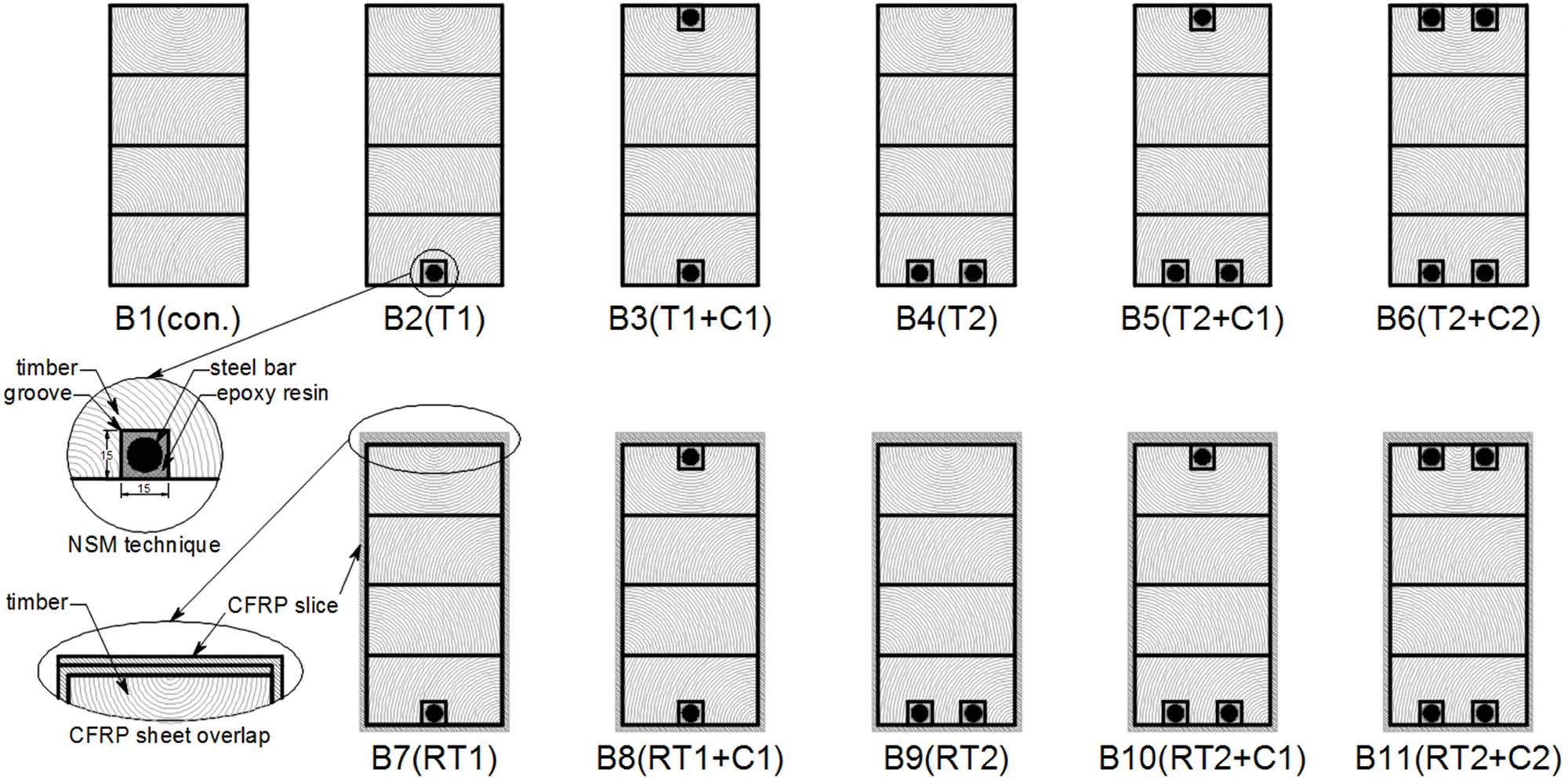
Specimens configuration.
Specimen identification
| Group | Symbol | Rein. bar location | Reinforcement ratio (%) | Wrapping CFRP sheet | ||
|---|---|---|---|---|---|---|
| Tension zone | Compression zone | Tension | Compression | |||
| Control | B1 (con.) | — | — | — | — | — |
| Group 1 | B2 (T1) | 1 | — | 0.528 | — | — |
| B3 (T1 + C1) | 1 | 1 | 0.528 | 0.528 | — | |
| B4 (T2) | 2 | — | 1.055 | — | — | |
| B5 (T2 + C1) | 2 | 1 | 1.055 | 0.528 | — | |
| B6 (T2 + C2) | 2 | 2 | 1.055 | 1.055 | — | |
| Group 2 | B7 (RT1) | 1 | — | 0.528 | — | 40 × 600@150 |
| B8 (RT1 + C1) | 1 | 1 | 0.528 | 0.528 | 40 × 600@150 | |
| B9 (RT2) | 2 | — | 1.055 | — | 40 × 600@150 | |
| B10 (RT2 + C1) | 2 | 1 | 1.055 | 0.528 | 40 × 600@150 | |
| B11 (RT2 + C2) | 2 | 2 | 1.055 | 1.055 | 40 × 600@150 | |

Wrapping reinforcement for beams of group 2.
In addition, Figure 5 shows a wrapping CFRP sheet reinforcement for the beams of group 2 only. The wrapping reinforcement was 40 × 600 CFRP sheet @150 mm, which was constant for all beams and distributed at the shear force region only along the beam.
The longitudinal reinforcement ratio of beams in groups 1 and 2 was regularly increased using the same steel bar diameter (i.e., Ø10 mm) to investigate the effect on flexural behavior of glulam timer beams at different reinforcement ratios at tension and compression zones. Also, wrapping reinforcement was constant and used for beams of group 2 only with the same longitudinal reinforcement of beam in group 1 to evaluate the effect of shear strengthening on glulam beam behavior.
2.4 Bending test and instrumentation
Glulam timber beams were imposed for testing in the basic laboratory of the College of Engineering at the University of Kufa. At a loading rate of 2.5 kN/min until failure, all specimen members were tested using a compression hydraulic machine of 2,000 kN. Also, at the bottom face of the beam center, the digital dial gauge (100 mm) was installed as shown in Figure 6.

Glulam timber beam setup for the test.
3 Results and discussion
Experimental results of glulam beam specimens were presented in terms of ultimate load capacity, failure mode, and deflected loaded beam response. Table 5 presents the results of all glulam beams. As a result, the strengthening NSM technique adopted in this study improved the structural performance in many aspects.
Specimen results
| Group | Symbol | P ultimate (kN) | Inc. (%) | Δ ultimate (mm) | Failure mode |
|---|---|---|---|---|---|
| Control | B1con. | 77 | — | 14.1 | Tensiona |
| Group 1 | B2-T1 | 89 | 16 | 15.5 | Compressionb then shear flowc at tension zone |
| B3-T1-C1 | 101 | 31 | 18.2 | Shear flow at tension zone | |
| B4-T2 | 105 | 36 | 17.1 | Compression then shear flow at compression zone | |
| B5-T2-C1 | 110 | 43 | 19.9 | Compression and shear flow at tension zone | |
| B6-T2-C2 | 113 | 47 | 19.5 | Tension knot and shear flow at tension zone | |
| Group 2 | B7R-T1 | 95 | 23 | 19.6 | Compression then shear flow at tension and cutting CFRPd |
| B8R-T1-C1 | 102 | 32 | 19.5 | Tension knot then shear at middle third zone and cutting CFRP | |
| B9R-T2 | 108 | 40 | 19.7 | Compression then shear flow at middle third and cutting CFRP | |
| B10R-T2-C1 | 114 | 48 | 19.1 | Shear flow at compression zone and cutting CFRP | |
| B11R-T2-C2 | 115 | 49 | 18.5 | Shear flow at middle third zone and cutting CFRP |
aFlexural brittle failure mode of timber at the tension zone.
cBrittle failure mode of timber initiated by horizontal cracks along the fiber direction.
bDuctile failure mode of timber at compression zone.
dBrittle failure mode initiated by debonding then cutting of wrapping CFRP sheet.
3.1 Load–deflection curves
From the bending test, Figure 7 displays the curves of load vs the maximum central point deflection of glulam beams of group 1 in comparison with the reference beam (i.e., unreinforced glulam beam) behavior. In addition, curves of group 2 specimens and the controlled beam are presented in Figure 8. It seems, the using of reinforcing bars at the tensile region of glulam beams enhanced the flexural capacity and decreased deflection values when compared with reference beam behavior as well as the ultimate load capacity were increased with considerable value in a range of (16–49)% due to the improvement in flexural stiffness which is a factor of moment capacity as well as the amount of reinforcement ratio. On the other hand, the wrapping reinforcement of the CFRP sheet of beams in group 2 did not provide a significant increment, and the curves of beams with and without reinforcement wrapping were relatively close to each other, and the percentage of ultimate load that increases between any pair of beams in the first and second groups (i.e., B2-T1 and B7R-T1 one five set of the coupled beam) not more than 7% which is less than what researchers expected due to inefficient wrapping reinforcement using strips of CFRP sheet which is sustained high strain to fail. Furthermore, Figure 9 demonstrates the load vs deflection response of reference members with coupled beams from groups 1 and 2.

Load–deflection response of group 1 beams.

Load–deflection response of group 2 beams.

Load–deflection response of coupled beams of groups 1 and 2. (a) Coupled beams B2-T1 and B7R-T1. (b) Coupled beams B3-T1 and B8R-T1. (c) Coupled beams B4-T1 and B9R-T1. (d) Coupled beams B5-T1 and B10R-T1. (e) Coupled beams B6-T1 and B11R-T1.
Introducing fully wrapped strips of CFRP sheet 40 mm × 600 mm at 150 mm c/c as shear reinforcement for RG members gave a small significant improvement in terms of flexural performance, and the range of increasing ultimate load capacity was 2–7% in comparison with the same reinforced specimen but without CFRP wrapped strips.
3.2 Failure modes
Failure mode description is one of the important results of experimental works; many factors affected various failure modes based on load arrangements, material characteristics, section properties, and knots, and other inherent timber imperfections were integrated to identify the failure mode. Mainly, three models of failure were recognized in this study, which are described as follows:
Tension failure was presented in an unreinforced glulam member (i.e., reference beam) in which the tensile stress at extreme fiber in the tension zone exceeded the tensile strength limit of the timber, then vertical cracks were introduced and brittle tension failure occurred as shown in Figure 10a.
Shear flow failure was admitted in the RG members in which the tensile and compressive stresses were withstood with the reinforcement, at which the failing shifted to shear flow failure mode as it exceeds the shear limit strength of the glulam timber. This failure was sudden and initiated by cracks propagated along fibril direction of timber as shown in Figure 10b.
Compression failure was presented in the RG beam in the compression zone, the strengthening of the tension reinforcement shifted the failing toward the compressive area. It is a ductile failure initiated by plastification of the extreme top fiber of the compression zone, then goes down till failure.

Failure modes recognized. (a) Tension failure. (b) Shear flow failure. (c) Compression failure.
The recognizing failure modes were associated with most of the specimens of groups 1 and 2 except the control glulam beam failed in pure tension failure mode. Generally, the RG member is initially loaded in tension and compression zones until the stress reached the strength limits, at this stage of loading if the reinforcement is introduced in the tension zone, the plastic stress in the outermost fiber of the compression zone reached then tends toward neutral axis location, at this stage of loading and if the reinforcement is introduced in a compressive zone the horizontal cracks of shear flow failure mode would be occurred depending on the shear strength limit. Furthermore, the presence of the knot and other timber imperfections could change the failure path as in specimens B6 and B8 in which the tension failure occurred due to the presence of the knot just above the zone of tension reinforcement as shown in Figure 11. In addition, the location of horizontal cracks of shear flow associated with compression or tension failure occurred in the top, middle, or bottom third of the cross-section depending on the amount of reinforcement ratio in tension and compression zones.

Associated failure modes. (a) Compression and shear flow failure B5. (b) Tension knot and shear flow failure B6. (c) Tension knot and shear flow failure B8. (d) Shear flow failure and cutting CRFP B11.
4 Theoretical model
As there is no established method for calculating the bending moment capacity of an RG timber beam, the present study introduced a specific model for the analysis of glued laminated timber beams reinforced by ordinary steel bars using the NSM technique. In this model, the principles of strain compatibility and forces equilibrium were considered, which were adopted by many researchers when dealing with RG beams [4,17].
Basic strain–stress curves and laws of constitutive for timber and steel are used as shown in Figure 12. Also, basic assumptions for pure flexural behavior were adopted, plain section, the perfect bond between bars and sides of timber grooves, and disregard knots and other wood defects.
![Figure 12
Constitutive laws of material [4]. (a) Stress–strain relation of timber. (b) Stress–strain relation of steel.](/document/doi/10.1515/eng-2022-0481/asset/graphic/j_eng-2022-0481_fig_012.jpg)
Constitutive laws of material [4]. (a) Stress–strain relation of timber. (b) Stress–strain relation of steel.
The nonlinear model was designed to evaluate the beam behavior including curvature, stiffness, ultimate load capacity, and deflection of the member until failure. With an incremental strain, the model simulated the overall behavior. At first, a small strain is assumed in the outer compressive edge, then the associated strain/stress state is evaluated across the cross-section, and these values are compared with the corresponding yield limits, considering the conditions of strain compatibility and forces equilibrium with the influence of timber plasticity and reinforcement yield, the load, moment, curvature, and deflection of stage load would be calculated. A small increase in strain is added if the stress/strain state does not cause any parts to fail. This process is repeated until it fails to perform. The theoretical RG beam model implemented two stages of loading depending on whether the compressive zone is plastified or not. The linear elastic stage and plastic stage of cross-section analysis of the RG beam with reinforcement in tension and compressive zones are presented in Figure 13. By introducing an initial small value of strain in the outermost fiber in compressive zone εci, the neutral axis is achieved according to the load stage using strain compatibility and force equilibrium equations (1–19).
Within the linear elastic stage:
strain compatibility includes
(1)(2)(3)where
Equilibrium forces include
(4)(5)where
The ultimate moment capacity of RG member can be evaluated from equation (6) as follows:
(6)where
Finally, the corresponding deflection of mid-point of RG beam can be calculated from equation (7) as follows:
(7)(8)(9)(10)where
Within the plastic stage:

Cross-section analysis of RG beam. (a) Elastic stage. (b) Plastic stage.
strain compatibility includes
where
where
Equilibrium forces include
where
Finally, the ultimate moment capacity of RG member can be evaluated from equation (17)
where
The corresponding deflection of the midpoint of RG beam can be calculated from equations ((7) and (8)), while the flexural rigidity of the plastic stage was evaluated from equation (18) as follows:
where
The tension failure model of the RG beam may have occurred when the tensile stress at the outermost filament in the tensile region reached the ultimate stress limitation of timber in tension
4.1 Theoretical model verification
Using the experimental properties of the timber and reinforcement steel bar, the verification of the theoretical model was carried out for different specimens with various reinforcement ratios to check the capability of the theoretical model to simulate the case under consideration as shown in Figure 14 and Table 6. A satisfactory agreement has been achieved between experimental and theoretical model results with 4 and 11% values of the largest variation coefficient COV of comparison results for ultimate loading and deflection, respectively.

Experimental and theoretical Comparison of load–deflection response of different RG beams.
Verification of theoretical and experimental results
| Symbol | P u-exp (kN) | P u-the (kN) |
|
Δ u–exp (mm) | Δ u–the (mm) |
|
|---|---|---|---|---|---|---|
| B1con. | 77 | 76.8 | 1.00 | 14.1 | 15.0 | 0.94 |
| B2-T1 | 89 | 87.6 | 1.02 | 15.5 | 15.8 | 0.98 |
| B3-T1-C1 | 101 | 98.9 | 1.02 | 18.2 | 15.7 | 1.16 |
| B4-T2 | 105 | 97.7 | 1.07 | 17.1 | 16.5 | 1.04 |
| B5-T2-C1 | 110 | 109.6 | 1.00 | 19.9 | 16.4 | 1.21 |
| B6-T2-C2 | 113 | 120.9 | 0.93 | 19.5 | 16.4 | 1.19 |
| Mean | 1.01 | 1.09 | ||||
| COV | 0.04 | 0.11 |
5 Conclusions
Based on the results of the experiments and the theoretical model presented in this study, it is possible to draw the following conclusions:
The NSM techniques using ordinary steel bars are effective ways of strengthening the glulam members in terms of flexural stiffness while increasing ultimate load capacity in a range of 16–49%.
The RG beams showed more strength as the tensile reinforcing ratio was increased as a result of the timber section tending to compression failure mode.
Mainly three parameters affected the flexural behavior of the RG beam, which were the reinforcement ratio, the timber stress ratio of ultimate tension to yield compression
A brittle tension failure mode dominated the failure mode in the unreinforced glulam member (i.e., reference beam) due to the absence of reinforcement in the tension zone.
The reinforcement ratio is the major factor in increasing the flexural strength of the RG member in failure mode. In the case of the horizontal shear, failure mode becomes dominant. There is no improvement in the strength properties of the RG beam, and the influence of the reinforcement ratio has vanished.
Though several theoretical predictions of flexural capacity were understated when compared to experimental predictions, these disparities were frequently about 10%, confirming that the proposed theoretical model was accurate, and the mean of P u_exp/P u_the and Δ u_exp/Δ u_the were 1.01 and 1.09, respectively.
Fully wrapped strips of CFRP sheet 40 mm × 600 mm at 150 mm c/c as shear reinforcement for RG members slightly improved flexural performance and ultimate load capacity by 2–7%.
Acknowledgments
The authors would also like to thank the staff of the laboratory of the College of Engineering at the University of Kufa.
-
Funding information: The authors state no funding involved.
-
Conflict of interest: The authors state no conflict of interest.
-
Data availability statement: The datasets generated during and/or analysed during the current study are available from the corresponding author on reasonable request.
References
[1] Vahedian A, Shrestha R, Crews K. Experimental and analytical investigation on CFRP strengthened glulam laminated timber beams: Full-scale experiments. Compos Part B: Eng. 2019;164:377–89.10.1016/j.compositesb.2018.12.007Search in Google Scholar
[2] Thorhallsson ER, Hinriksson GI, Snæbjörnsson JT. Strength and stiffness of glulam beams reinforced with glass and basalt fibers. Compos Part B: Eng. 2017;115:300–7.10.1016/j.compositesb.2016.09.074Search in Google Scholar
[3] Al-Katib HAA, Alkhudery HH, Al-Tameemi HA. Structural behavior of standard timber beams strengthened using CFRP sheet. Asian J Civ Eng. 2022;23:727–39. 10.1007/s42107-022-00452-w.Search in Google Scholar
[4] Yeboah D, Gkantou M. Investigation of flexural behaviour of structural timber beams strengthened with NSM basalt and glass FRP bars. Structures. 2021;33:390–405.10.1016/j.istruc.2021.04.044Search in Google Scholar
[5] Johnsson H, Blanksvärd T, Carolin A. Glulam members strengthened by carbon fiber reinforcement. Mater Struct. 2006;40:47–56.10.1617/s11527-006-9119-7Search in Google Scholar
[6] Fiorelli J, Alves A. Glulam beams reinforced with FRP externally-bonded: Theoretical and experimental evaluation. Mater Struct. 2011;44:1431–40.10.1617/s11527-011-9708-ySearch in Google Scholar
[7] Corradi M, Vo TP, Poologanathan K, Osofero AI. Flexural behaviour of hardwood and softwood beams with mechanically connected GFRP plates. Compos Struct. 2018;206:610–20.10.1016/j.compstruct.2018.08.056Search in Google Scholar
[8] Ling Z, Liu W, Shao J. Experimental and theoretical investigation on shear behaviour of small-scale timber beams strengthened with Fiber-Reinforced Polymer composites. Compos Struct. 2020;240:111989.10.1016/j.compstruct.2020.111989Search in Google Scholar
[9] De Lorenzis L, Teng JG. Near-surface mounted FRP reinforcement: an emerging technique for strengthening structures. Compos Part B: Eng. 2007;38(2):119–43. 10.1016/j.compositesb.2006.08.003.Search in Google Scholar
[10] Alkhudery HH, Albuthbahak OM, Al-Katib HA. Investigation of effective hybrid FRP and steel reinforcement ratio for concrete members. J Eng App Sci. 2018;13(13):5150–61.Search in Google Scholar
[11] Kálmán Szabó Z, Balázs GL. Near surface mounted FRP reinforcement for strengthening of concrete structures. Period Polytech Civ Eng. 2007;51(1):33–8. 10.3311/pp.ci.2007-1.05.Search in Google Scholar
[12] Poletti E, Vasconcelos G, Jorge M. Application of near surface mounted (NSM) strengthening technique to traditional timber frame walls. Constr Build Mater. 2015;76:34–50.10.1016/j.conbuildmat.2014.11.022Search in Google Scholar
[13] Glišović I, Stevanović B, Todorović M. Flexural reinforcement of glulam beams with CFRP plates. Materials and Structures. 2016;49:2841–55.10.1617/s11527-015-0690-7Search in Google Scholar
[14] Gentile C, Svecova D, Rizkalla SH. Timber beams strengthened with GFRP bars: Development and Applications. J Compos Constr. 2002;6(1):11–20. 10.1061/(ASCE)1090-0268(2002)6:1(11).Search in Google Scholar
[15] Raftery GM, Harte AM. Nonlinear numerical modelling of FRP reinforced glued laminated timber. Compos B Eng. 2013;52:40–50.10.1016/j.compositesb.2013.03.038Search in Google Scholar
[16] Raftery GM, Kelly F. Basalt FRP rods for reinforcement and repair of timber. Comp B Eng. 2015;70:9–19. 10.1016/j.compositesb.2014.10.036.Search in Google Scholar
[17] Yang H, Liu W, Lu W, Zhu S, Geng O. Flexural behavior of FRP and steel reinforced glulam beams: experimental and theoretical evaluation. Const Build Mat. 2016;106:550–63. 10.1016/j.conbuildmat.2015.12.135.Search in Google Scholar
[18] Bakalarz MM, Kossakowski PG, Tworzewski P. Strengthening of bent LVL beams with near-surface mounted (NSM) FRP reinforcement. Materials. 2020;13(10):2350.10.3390/ma13102350Search in Google Scholar PubMed PubMed Central
[19] Barragán OG, Jacob J. Flexural strengthening of glued laminated timber beams with steel and carbon fiber reinforced polymers. Master’s thesis. Department of Civil and Environmental Engineering, Chalmers University of Technology; 2007.Search in Google Scholar
© 2023 the author(s), published by De Gruyter
This work is licensed under the Creative Commons Attribution 4.0 International License.
Articles in the same Issue
- Regular Articles
- Design optimization of a 4-bar exoskeleton with natural trajectories using unique gait-based synthesis approach
- Technical review of supervised machine learning studies and potential implementation to identify herbal plant dataset
- Effect of ECAP die angle and route type on the experimental evolution, crystallographic texture, and mechanical properties of pure magnesium
- Design and characteristics of two-dimensional piezoelectric nanogenerators
- Hybrid and cognitive digital twins for the process industry
- Discharge predicted in compound channels using adaptive neuro-fuzzy inference system (ANFIS)
- Human factors in aviation: Fatigue management in ramp workers
- LLDPE matrix with LDPE and UV stabilizer additive to evaluate the interface adhesion impact on the thermal and mechanical degradation
- Dislocated time sequences – deep neural network for broken bearing diagnosis
- Estimation method of corrosion current density of RC elements
- A computational iterative design method for bend-twist deformation in composite ship propeller blades for thrusters
- Compressive forces influence on the vibrations of double beams
- Research on dynamical properties of a three-wheeled electric vehicle from the point of view of driving safety
- Risk management based on the best value approach and its application in conditions of the Czech Republic
- Effect of openings on simply supported reinforced concrete skew slabs using finite element method
- Experimental and simulation study on a rooftop vertical-axis wind turbine
- Rehabilitation of overload-damaged reinforced concrete columns using ultra-high-performance fiber-reinforced concrete
- Performance of a horizontal well in a bounded anisotropic reservoir: Part II: Performance analysis of well length and reservoir geometry
- Effect of chloride concentration on the corrosion resistance of pure Zn metal in a 0.0626 M H2SO4 solution
- Numerical and experimental analysis of the heat transfer process in a railway disc brake tested on a dynamometer stand
- Design parameters and mechanical efficiency of jet wind turbine under high wind speed conditions
- Architectural modeling of data warehouse and analytic business intelligence for Bedstead manufacturers
- Influence of nano chromium addition on the corrosion and erosion–corrosion behavior of cupronickel 70/30 alloy in seawater
- Evaluating hydraulic parameters in clays based on in situ tests
- Optimization of railway entry and exit transition curves
- Daily load curve prediction for Jordan based on statistical techniques
- Review Articles
- A review of rutting in asphalt concrete pavement
- Powered education based on Metaverse: Pre- and post-COVID comprehensive review
- A review of safety test methods for new car assessment program in Southeast Asian countries
- Communication
- StarCrete: A starch-based biocomposite for off-world construction
- Special Issue: Transport 2022 - Part I
- Analysis and assessment of the human factor as a cause of occurrence of selected railway accidents and incidents
- Testing the way of driving a vehicle in real road conditions
- Research of dynamic phenomena in a model engine stand
- Testing the relationship between the technical condition of motorcycle shock absorbers determined on the diagnostic line and their characteristics
- Retrospective analysis of the data concerning inspections of vehicles with adaptive devices
- Analysis of the operating parameters of electric, hybrid, and conventional vehicles on different types of roads
- Special Issue: 49th KKBN - Part II
- Influence of a thin dielectric layer on resonance frequencies of square SRR metasurface operating in THz band
- Influence of the presence of a nitrided layer on changes in the ultrasonic wave parameters
- Special Issue: ICRTEEC - 2021 - Part III
- Reverse droop control strategy with virtual resistance for low-voltage microgrid with multiple distributed generation sources
- Special Issue: AESMT-2 - Part II
- Waste ceramic as partial replacement for sand in integral waterproof concrete: The durability against sulfate attack of certain properties
- Assessment of Manning coefficient for Dujila Canal, Wasit/-Iraq
- Special Issue: AESMT-3 - Part I
- Modulation and performance of synchronous demodulation for speech signal detection and dialect intelligibility
- Seismic evaluation cylindrical concrete shells
- Investigating the role of different stabilizers of PVCs by using a torque rheometer
- Investigation of high-turbidity tap water problem in Najaf governorate/middle of Iraq
- Experimental and numerical evaluation of tire rubber powder effectiveness for reducing seepage rate in earth dams
- Enhancement of air conditioning system using direct evaporative cooling: Experimental and theoretical investigation
- Assessment for behavior of axially loaded reinforced concrete columns strengthened by different patterns of steel-framed jacket
- Novel graph for an appropriate cross section and length for cantilever RC beams
- Discharge coefficient and energy dissipation on stepped weir
- Numerical study of the fluid flow and heat transfer in a finned heat sink using Ansys Icepak
- Integration of numerical models to simulate 2D hydrodynamic/water quality model of contaminant concentration in Shatt Al-Arab River with WRDB calibration tools
- Study of the behavior of reactive powder concrete RC deep beams by strengthening shear using near-surface mounted CFRP bars
- The nonlinear analysis of reactive powder concrete effectiveness in shear for reinforced concrete deep beams
- Activated carbon from sugarcane as an efficient adsorbent for phenol from petroleum refinery wastewater: Equilibrium, kinetic, and thermodynamic study
- Structural behavior of concrete filled double-skin PVC tubular columns confined by plain PVC sockets
- Probabilistic derivation of droplet velocity using quadrature method of moments
- A study of characteristics of man-made lightweight aggregate and lightweight concrete made from expanded polystyrene (eps) and cement mortar
- Effect of waste materials on soil properties
- Experimental investigation of electrode wear assessment in the EDM process using image processing technique
- Punching shear of reinforced concrete slabs bonded with reactive powder after exposure to fire
- Deep learning model for intrusion detection system utilizing convolution neural network
- Improvement of CBR of gypsum subgrade soil by cement kiln dust and granulated blast-furnace slag
- Investigation of effect lengths and angles of the control devices below the hydraulic structure
- Finite element analysis for built-up steel beam with extended plate connected by bolts
- Finite element analysis and retrofit of the existing reinforced concrete columns in Iraqi schools by using CFRP as confining technique
- Performing laboratory study of the behavior of reactive powder concrete on the shear of RC deep beams by the drilling core test
- Special Issue: AESMT-4 - Part I
- Depletion zones of groundwater resources in the Southwest Desert of Iraq
- A case study of T-beams with hybrid section shear characteristics of reactive powder concrete
- Feasibility studies and their effects on the success or failure of investment projects. “Najaf governorate as a model”
- Optimizing and coordinating the location of raw material suitable for cement manufacturing in Wasit Governorate, Iraq
- Effect of the 40-PPI copper foam layer height on the solar cooker performance
- Identification and investigation of corrosion behavior of electroless composite coating on steel substrate
- Improvement in the California bearing ratio of subbase soil by recycled asphalt pavement and cement
- Some properties of thermal insulating cement mortar using Ponza aggregate
- Assessment of the impacts of land use/land cover change on water resources in the Diyala River, Iraq
- Effect of varied waste concrete ratios on the mechanical properties of polymer concrete
- Effect of adverse slope on performance of USBR II stilling basin
- Shear capacity of reinforced concrete beams with recycled steel fibers
- Extracting oil from oil shale using internal distillation (in situ retorting)
- Influence of recycling waste hardened mortar and ceramic rubbish on the properties of flowable fill material
- Rehabilitation of reinforced concrete deep beams by near-surface-mounted steel reinforcement
- Impact of waste materials (glass powder and silica fume) on features of high-strength concrete
- Studying pandemic effects and mitigation measures on management of construction projects: Najaf City as a case study
- Design and implementation of a frequency reconfigurable antenna using PIN switch for sub-6 GHz applications
- Average monthly recharge, surface runoff, and actual evapotranspiration estimation using WetSpass-M model in Low Folded Zone, Iraq
- Simple function to find base pressure under triangular and trapezoidal footing with two eccentric loads
- Assessment of ALINEA method performance at different loop detector locations using field data and micro-simulation modeling via AIMSUN
- Special Issue: AESMT-5 - Part I
- Experimental and theoretical investigation of the structural behavior of reinforced glulam wooden members by NSM steel bars and shear reinforcement CFRP sheet
- Improving the fatigue life of composite by using multiwall carbon nanotubes
- A comparative study to solve fractional initial value problems in discrete domain
- Assessing strength properties of stabilized soils using dynamic cone penetrometer test
- Investigating traffic characteristics for merging sections in Iraq
- Enhancement of flexural behavior of hybrid flat slab by using SIFCON
- The main impacts of a managed aquifer recharge using AHP-weighted overlay analysis based on GIS in the eastern Wasit province, Iraq