Seismic evaluation cylindrical concrete shells
-
Aqeel M. Hammood
 and
David A. M. Jawad
and
David A. M. Jawad

Abstract
The reasons for concrete roof shells’ apparent seismic resistance have been subject to limited research but they have been shown to be inherently resilient to earthquakes. Shells constructed of concrete exhibit high structural efficiency and can therefore be made very thin. As a result of their relatively lightweight nature, thin shell structures are implicitly resistant to earthquake forces. The shell structure is typically designed so that it performs optimally under gravity loads, which are carried mainly by membrane action over the shell surface. As earthquakes induce unexpected horizontal forces, concrete shell structures can be damaged by bending stresses. By studying 8 cm-thick concrete roof shells using parametric analysis, this research shows that small and midsized (span <30 m) thin concrete roof shells can indeed be intrinsically earthquake resistant. These structures have high geometric stiffness and low mass, which results in fundamental frequencies far higher than those of realistic seismic events. Under earthquake excitation, these characteristics result in elastic shell behavior, without exceeding the maximum concrete strength. A shallow shell exhibits greater stress in response to earthquake vibrations caused by the vertical components than by horizontal components. Further, by increasing the rise and curvature of large shells, the fundamental frequency increases and the damaging effect of vertical earthquake vibration is reduced. The aim of this study in general is to show the analysis and the effect of earthquakes on cylindrical concrete shells.
1 Introduction
A thin concrete shell is used for a variety of purposes, including roofs for public spaces, auditoriums, and industrial facilities [1]. It is possible to span large spaces without using interior supports with thin concrete shell roofs, as they have a high strength-to-weight ratio and are highly rigid [2]. In the past decade, large span thin shell-reinforced concrete roof structures have demonstrated their ability to withstand extreme loads during natural disasters. As an example, Félix Candela’s reinforced concrete roof shell structures (Mexico City, 1950–1960s) survived the 8.0 Mw earthquake that shook Mexico city in 1985 without damage [3].
Cylindrical shells have a singly curved shell, developable surface, and commonly an arc-shaped cross-section. Besides two straight edges parallel to the cylinder’s axis, the surface has two curved edges perpendicular to the axis. The length-to-radius ratio of cylindrical shells can be classified as long (L/R > 5) or short (L/R < 1) and intermediate between them. Across the longitudinal edge of a short cylindrical shell, loads are transferred to transverse supports by deep beams on the shell’s edge sections. In long cylindrical shells, it behaves as a large beam with a thin curved section, although there is still some arching near the crown [4].
These structures are often the result of collaboration between architects, engineers, and builders. In many cases, roof shells are built simultaneously by architects and engineers in different parts of the world. For example, consider the roof shells designed by Isler (Switzerland), Candela (Mexico), and Nervi (Italy). In terms of the number and variety of concrete shells built, the 1920s to early 1960s are considered the golden age of concrete shell construction. The number of concrete shells built and the articles published on their analysis and design methods have decreased steadily since then. This was largely caused by the difficulty of building concrete shells as well as some serious collapses [5,6].
In response to an earthquake, buildings shake for a few seconds. During this time, multiple types of seismic waves are combined to shake the building in different ways, depending on which earthquake is occurring. Due to variations in fault slippage, different rock types through which the waves pass and different geological characteristics at each location, the resultant shaking differs at each one. Each building is different, whether in size, configuration, material, structural system, method of analysis, or age and quality of construction; each of these characteristics affects the building’s response [7].
The authors are not aware of any thin concrete shell structure that sustained significant structural damage as a result of an earthquake. Due to the curved geometry of shells, they are very thin and have high structural efficiency. Thus, the forces generated by dynamic actions such as earthquakes are relatively low because they are directly proportional to the mass of the shell. It is the overall shape of a shell structure that is most important among the common design parameters, such as support conditions, material, thickness, and overall shape, that determines if a shell will have enough safety, stability, and stiffness to span a space without intermediate supports [8]. However, roof shell structures are usually shaped in a way that allows gravity loading to be applied optimally [9]. Furthermore, they often carry loads to the foundation through membrane action, thus avoiding tensile stresses caused by bending [3]. Nevertheless, earthquake-induced bending moments could cause structural damage to shells. Designing shells in earthquake-prone regions differs from typical shell design in that, instead of focusing on gravity loads, more attention needs to be paid to the strength of the shell against large bending moments [10]. In this study, three types of short, intermediate, and long cylindrical concrete shells are presented, and they were exposed to the Landers and El-Centro earthquakes. The results were compared with those of Michiels and Adriaenssens [11], noting that they studied the square type of concrete shells.
2 Methodology description
In this study, parametric analyses are used to examine the effect of shell geometry on the vibrational properties and earthquake resilience of a concrete roof shell with a different size plan. The purpose of this study is to assess the performance of singly curved shells based on response spectrum analysis of recorded spectra and to determine the key design parameters that will produce a shell structure for the same plan area that is more durable and effective in resisting stresses and deformations. The flowchart shown in Figure 1 illustrates the research methodology.

Flowchart illustrating the research methodology.
2.1 Shell geometry and material properties
Three types of concrete cylindrical shells, long, medium, and short shell cylinders, were analyzed, starting with variable plan dimensions, a thickness of 8 cm and an angle of 60° against curvature, as indicated by the first group. The thickness of the concrete shell for the second group was changed according to the fixed span of 20 m and the angle of curvature of 60°. In the last group, the curvature angle was changed for each concrete shell type with an 8 cm thickness and a 20 m span as well. Each of the above cases is simply supported (Figure 2).
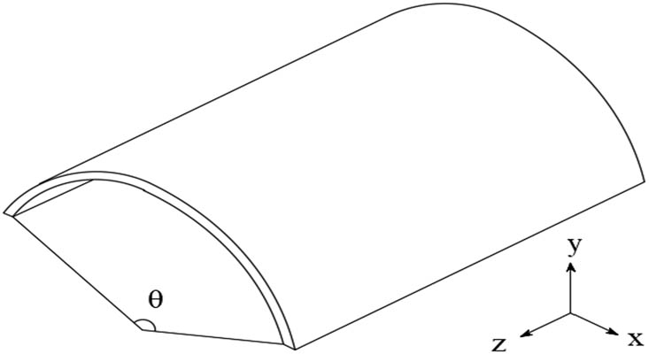
Cylindrical shell; perpendicular displacements in the horizontal plane are permitted. Displacements vertically and parallel to the edge are restrained.
The material properties used in the finite element implementation via ANSYS 21R2 software [12] are given in Table 1.
Material properties used for the parametric study [11]
| Compressive strength | 30 MPa |
| Tensile strength | 3 MPa |
| Young’s modulus | 21.5 GPa |
| Density | 2,400 kg/m3 |
| Poisson’s ratio | 0.2 |
2.2 Numerical modeling of concrete shells
Solid elements (SOLID65) with eight nodes are used to model the concrete shell material, which includes three degrees of freedom at each point and translations in x, y, and z directions. Also, this element is capable of plastic deformation, cracking in the x, y, and z directions, until it reaches the crushed concrete [13]. In modeling concrete materials, the element-type SOLID65 provides results by calculating the nonlinear behavior of concrete shells [14].
2.3 Modal analysis and earthquake response
Besides performing a response spectrum analysis, the earthquake response of the shell is also determined indirectly by evaluating its fundamental frequencies. The eigenvalues and corresponding eigenmodes of a shell depend only on its stiffness and mass distribution, and as such, are independent of its loading. A normal mode analysis can be used to determine these values by solving
where K is the stiffness matrix of the shell structure and M is the mass matrix. The eigenvalues of the shell can be represented by vector λ and the corresponding eigenvectors by vector ϕ. The Lanczos algorithm is used to calculate n eigenvalues λ and n eigenvectors ϕ, where n is the number of degrees of freedom [15]. Based on the excitation and the mass participation factor for each eigenvalue, corresponding modal shapes contribute to the dynamic response of the system. A response spectrum analysis is used to determine the response of each shape to the seismic input spectra in addition to determining the fundamental frequencies [16]. First, the response spectrum of the 1992 7.3 Mw Landers earthquake in California, USA (Figure 3), was used as an earthquake input. Model calibration used this earthquake input as the earthquake response of another shell reported in the study of Ostovari Dailamani [17]. An additional factor that made the earthquake so relevant is that it had a particularly strong vertical component. The vertical component of the shells studied in this article is more significant than the horizontal component, which will be discussed in Section 3.2. The second spectrum is derived from the El-Centro earthquake in 1940, in Southern California (Figure 4). The reason why a response spectrum analysis is used instead of a time history analysis is that a response spectrum analysis is more computationally efficient, allowing for more parametric variations to be processed more effectively. In addition, since the behavior of the shells in this study is elastic, only the maximum response of the structure is of significant interest, while the evolution of the response over time provides little value to the research.
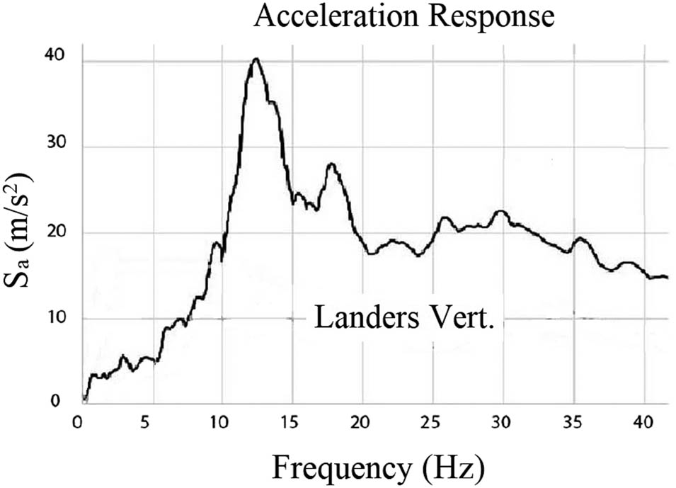
The acceleration response spectrum for the vertical component of the Landers earthquake.
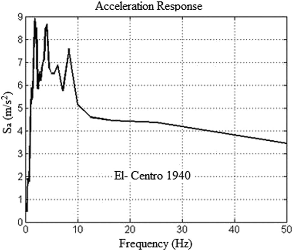
The acceleration response spectrum of the El-Centro 1940 earthquake in the vertical direction.
2.4 Variation in shape
Generally, structures with high fundamental frequencies are well suited to withstand both vertical and horizontal external forces. Typically, the displacement response decreases with increasing frequency (Figure 5). By examining the seismic spectrum, it is noted that in large spaces from 30 to 50 m, there is a slight change in low frequencies, which gives higher deformations. As the concrete shell thickness increases (Figure 6), the frequency increases, which naturally reduces deformation. With respect to changing the curvature angle θ (Figure 7), we notice that the bigger the angle, the higher the rigidity of the structure, and thus the decreased deformations in it. These results were adopted for the Landers and El-Centro earthquakes. There was a slight difference in the deformation values of concrete shells, with some oscillations in them that might be due to the convergence of seismic frequencies with the natural frequency of the concrete shell, leading to high deformation values.
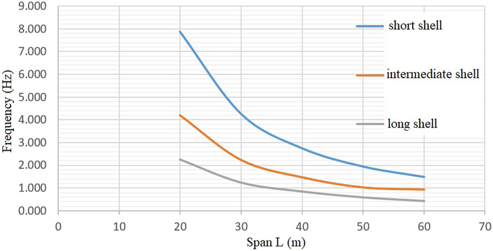
Evolution of frequency for reinforced concrete cylindrical shells with a constant thickness of 8 cm and variable span.
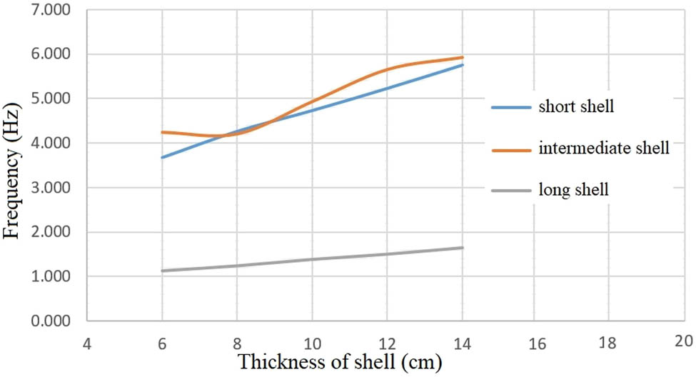
Evolution of frequency for reinforced concrete cylindrical shells with a constant span and variable thickness.
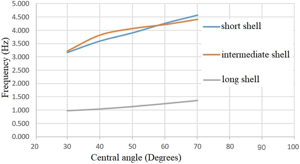
Evolution of frequency for reinforced concrete cylindrical shells with a constant thickness of 8 cm and variable central angle.
An approach to understanding the seismic behavior of shells is to determine whether the fundamental frequencies of the analyzed shells fall within these low-frequency ranges and to determine the parametric variations of the initial shell shape for which the fundamental frequency is at the highest level. It is acceptable to increase the shell’s fundamental frequencies as long as this results in the elasticity of the shell structure. Reinforced concrete shells form plastic hinges if their elastic limit is exceeded, and these hinges will reduce the shell’s stiffness and therefore its fundamental frequency. Therefore, it can be assumed that the adopted elastic approach applies to thin reinforced concrete shells.
3 Results
3.1 Validations
The normal modes and response spectrum analyses are initially calibrated for a 20 m × 20 m, 0.08 m-thick shell with 60° curvature, as reported by Michiels and Adriaenssens [11]. During model validation, deformations due to the vertical component of the Landers earthquake were determined using mesh convergence analysis, modal analysis with modal mass participation analysis, and response spectrum analysis [16]. In Section 2.1, a parametric analysis is performed to determine a realistic plan size. It is shown that 8 cm-thick singly curved shells of this form with spans greater than 50 m will fail due to large deformations. Additionally, for shells with spans greater than 30 m, the concrete’s maximum tensile strength (3 MPa) is exceeded locally. The Landers earthquake had this result, but the El-Centro earthquake had all stresses developed as less than 3 MPa.
Studies of cylindrical shells with spans less than 30 m demonstrate that their fundamental frequencies are higher than 4 Hz, not coincident with earthquake frequencies (Landers and El-Centro 1940). As a result, earthquakes should have little effect on these shells. In order to confirm this hypothesis of favorable behavior based on a high fundamental frequency, a span of (20 × 10) m was chosen for the short shell, (20 × 20) m for the intermediate shell, and (20 × 40) m for the long shell as a base model for an in-depth analysis under earthquake loading. The rise of the shell is 2.68 m (a 60° central angle), and the calculated fundamental frequencies are 7.88, 4.21, and 2.26 Hz for short, intermediate, and long shell, respectively. The maximum deformation under the self-weight condition did not exceed 0.5 mm. The deformation of this shape is lower than the span of the shell divided by 200, which is used as a criterion for maximum deflection, where
The stress values throughout the shells are low under a self-weight (Figures 8–10). As a result of the self-weight of the concrete shell, maximum stress values are found at its top. Based on a conservative reinforced concrete compressive strength of 30 MPa and the corresponding tensile strength of 3 MPa, the concrete shell will not crack under a self-weight since the maximum permissible compressive and tensile stresses are never exceeded.
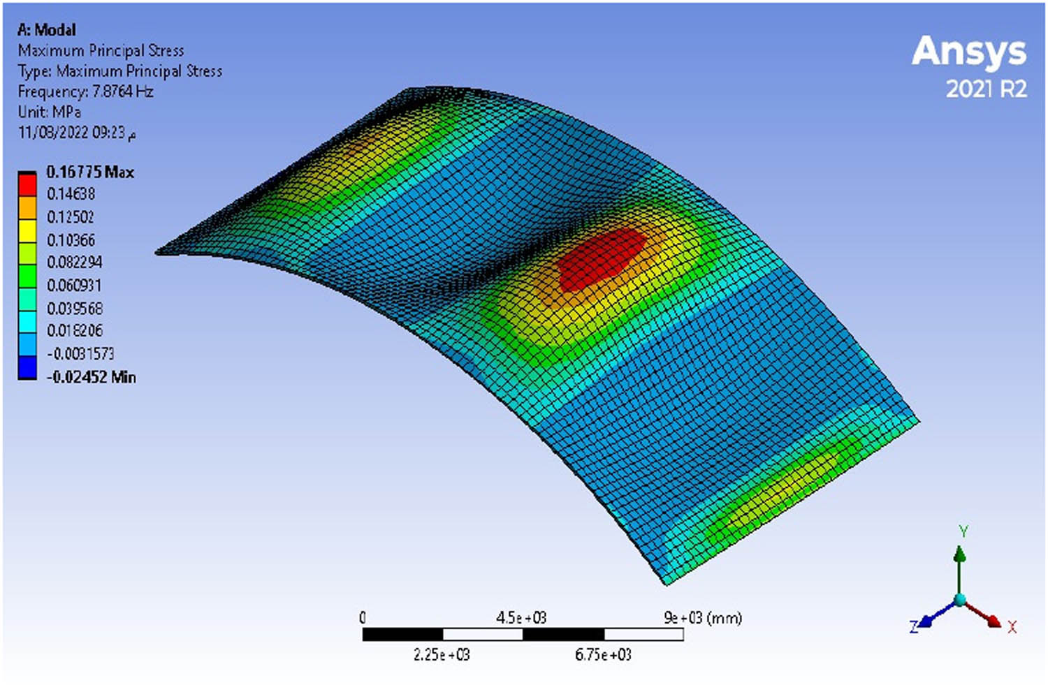
Maximum stress under self-weight in the short shell with a span of (20 × 10) m.
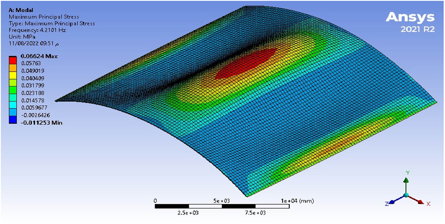
Maximum stress under a self-weight in the intermediate shell with a span of (20 × 20) m.
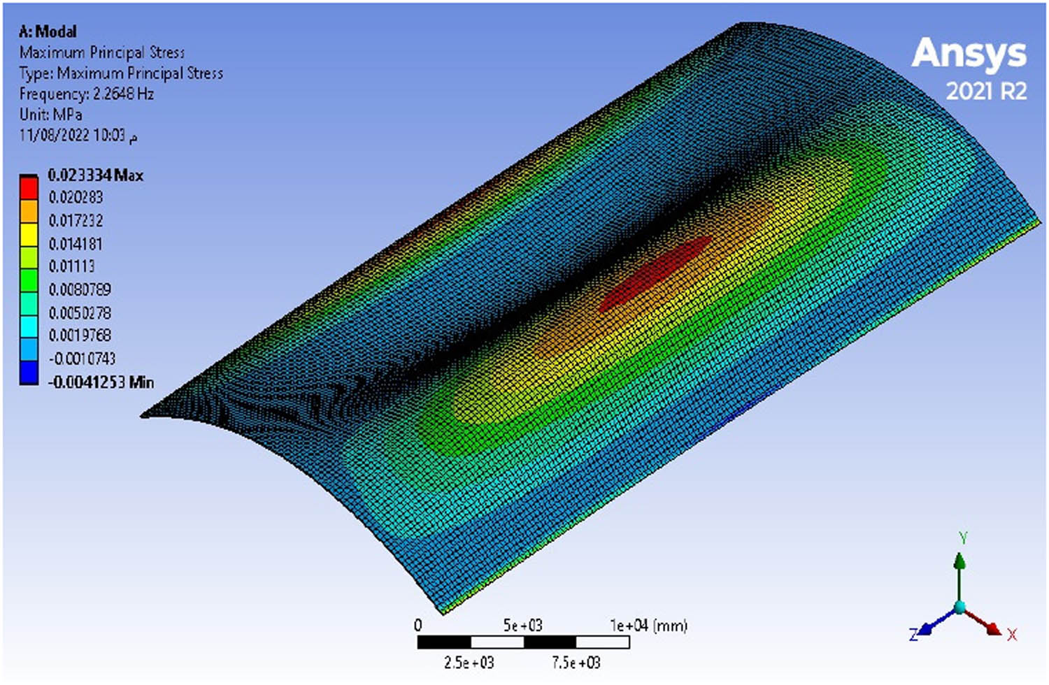
Maximum stress under self-weight in a long shell with a span of (20 × 40) m.
3.2 Response to the initial earthquake
There are two earthquake spectra used in the models: one for the vertical components of the Landers earthquake (Figure 3) and one for El-Centro 1940 (Figure 4). Landers’ vertical component is more important than its horizontal component because the vertical component is much larger (about four times at peak response). For an earthquake, this behavior is atypical, and a large vertical component is only realistic in near-field events but is often much more destructive [19]. As compared with the Landers earthquake, the El-Centro spectrum exhibits a greater proportion of lower frequencies. The response spectra analysis indicates, however, that the deformation values of the concrete shells give greater results in the case of vertical earthquake components (for the Landers and El-Centro earthquakes and for concrete shells of short, intermediate, and long lengths, it does not exceed 3 cm), mostly (Tables 2–4). Additionally, the vertical component causes much higher maximum stresses. Since the shells under investigation are relatively shallow, this conclusion is not unexpected. As a result, they are more susceptible to vertical loading, which operates mostly out-of-plane, than to horizontal loading, which operates in-plane. For the shells, the normal stresses imposed by Landers’ were 2.6–4.2, 1.4–3.6, and 2.5–3.9 MPa for short, intermediate, and long shells, respectively, and in the case of the El-Centro earthquake, the normal stresses were between 0.5–3.3, 0.3–3.9, and 1.8–11.6 MPa for short, medium, and long shells, respectively. Although the stress values in the El-Centro earthquake are mostly within the permissible range to withstand the elastic behavior, because the tensile strength of concrete (3 MPa) is not exceeded mostly, in the Landers earthquake, the maximum permissible tensile strength of concrete is exceeded, which affects the earthquake on the shells in some cases. As a result of these stresses, cracking would occur in the shell structure and the reinforcement would be activated, affecting fundamental frequencies through stiffness reduction. Additionally, by selecting a smaller span, for example 20 m, the maximum principal stresses under vertical earthquake loading would not exceed 3 MPa for both earthquakes, thus ensuring elastic behavior (Figures 11 and 12). The results were compared with the fundamental frequency; according to the research, it was 3.63 Hz and it appeared to us as 4.1 Hz. The vertical deformation was 1.2 cm, while according to our analysis it was 1.271 cm, as shown in Figure 4 and Table 3, of the results of the Landers earthquake for a cylindrical concrete shell 20 m × 20 m, where the results are very similar.
Total deformations and maximum normal stresses of short shells
| Span (m) | Max. deformation (cm) | Max. normal stress (MPa) | ||
|---|---|---|---|---|
| Landers | El-Centro | Landers | El-Centro | |
| 20 | 0.286 | 0.089 | 2.564 | 0.558 |
| 30 | 0.997 | 0.270 | 3.998 | 0.929 |
| 40 | 0.878 | 0.768 | 4.268 | 1.720 |
| 50 | 1.106 | 1.561 | 4.189 | 3.289 |
| 60 | 1.098 | 1.919 | 2.829 | 3.307 |
Total deformations and maximum normal stresses of intermediate shells
| Span (m) | Max. deformation (cm) | Max. normal stress (MPa) | ||
|---|---|---|---|---|
| Landers | El-Centro | Landers | El-Centro | |
| 20 | 1.271 | 0.419 | 1.859 | 1.256 |
| 30 | 0.832 | 1.315 | 2.825 | 2.144 |
| 40 | 1.457 | 2.934 | 3.627 | 3.965 |
| 50 | 2.174 | 3.906 | 2.497 | 3.867 |
| 60 | 3.653 | 4.121 | 3.423 | 3.765 |
Total deformations and maximum normal stresses of long shells
| Span (m) | Max. deformation (cm) | Max. normal stress (MPa) | ||
|---|---|---|---|---|
| Landers | El-Centro | Landers | El-Centro | |
| 20 | 0.811 | 1.024 | 2.520 | 1.766 |
| 30 | 1.668 | 3.215 | 3.967 | 5.623 |
| 40 | 3.985 | 5.990 | 2.986 | 4.457 |
| 50 | 7.549 | 10.822 | 3.444 | 6.185 |
| 60 | 13.938 | 13.004 | 5.242 | 11.560 |
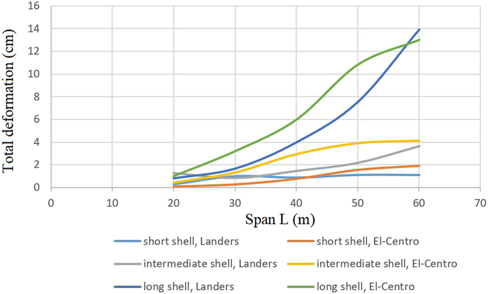
Total deformations with different span lengths of shells, subjected to the vertical components of Landers and El-Centro earthquakes.
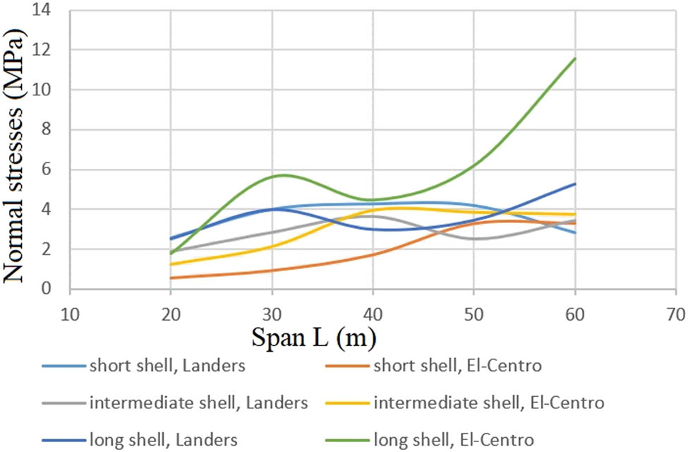
Maximum normal stresses with different span lengths of shells, subjected to the vertical components of Landers and El-Centro earthquakes.
3.3 Effect of shell dimensions
The changing shape of the shells will show that the fundamental frequency and stiffness can be altered and excessive stresses resulting from vertical excitations can also be avoided.
The first approach to reduce earthquake-induced deformations and stresses is by increasing the fundamental shell frequency via increasing the shell thickness and keeping the span constant (Figures 6, 13 and 14). The central angle of each shell is kept constant at 60°. The plan size is kept constant at 30 m × 15 m, 20 m × 20 m, and 30 m × 60 m for short, intermediate, and long shells, respectively, and the geometry is still based on a cylinder and all other design parameters remain unchanged.
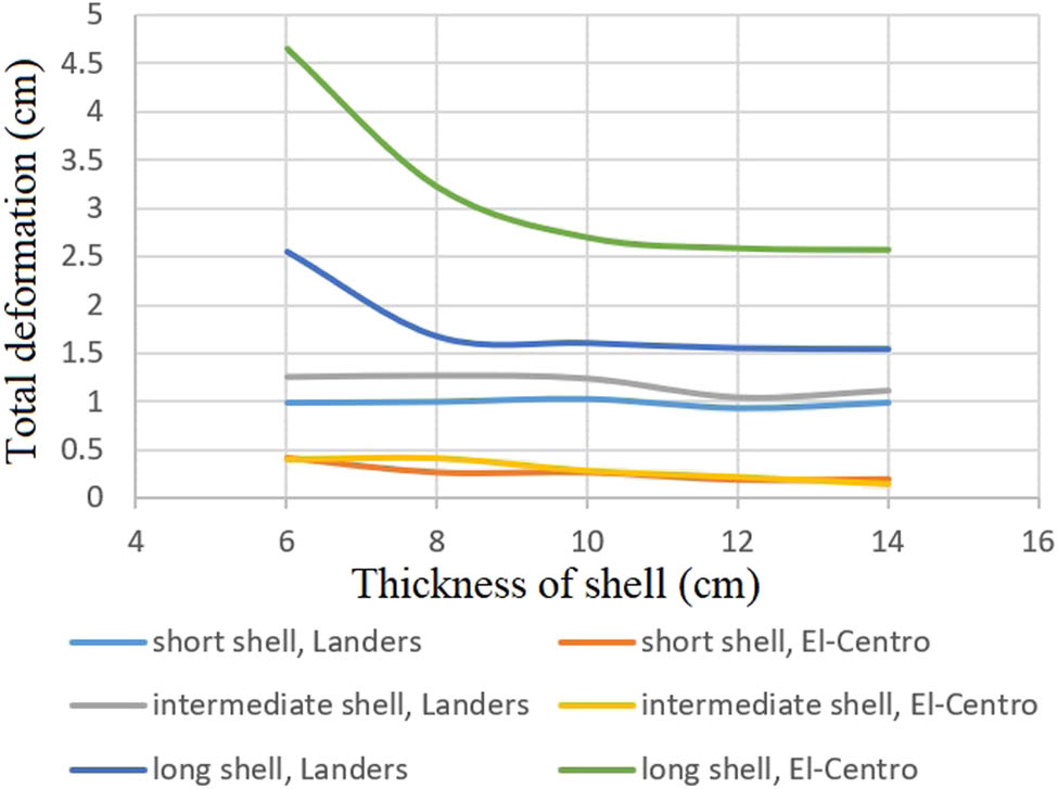
Total deformations with different thicknesses of shells, subjected to the vertical components of Landers and El-Centro earthquakes.
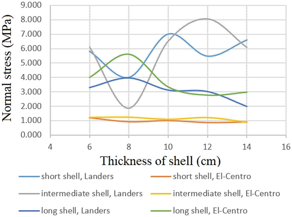
Maximum normal stresses with different thicknesses of shells, subjected to the vertical components of Landers and El-Centro earthquakes.
In addition to increasing the fundamental frequency of the shell, the angle at which it is included (Figures 7, 15 and 16) can also be adjusted to reduce earthquake response. Each shell’s thickness is kept uniform at 8 cm. The geometric stiffness increases with curvature, and fundamental frequencies increase almost linearly.
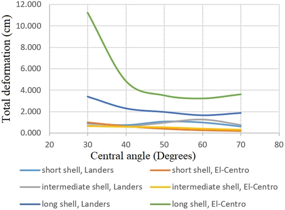
Total deformations with different central angles of shells, subjected to the vertical components of Landers and El-Centro earthquakes.
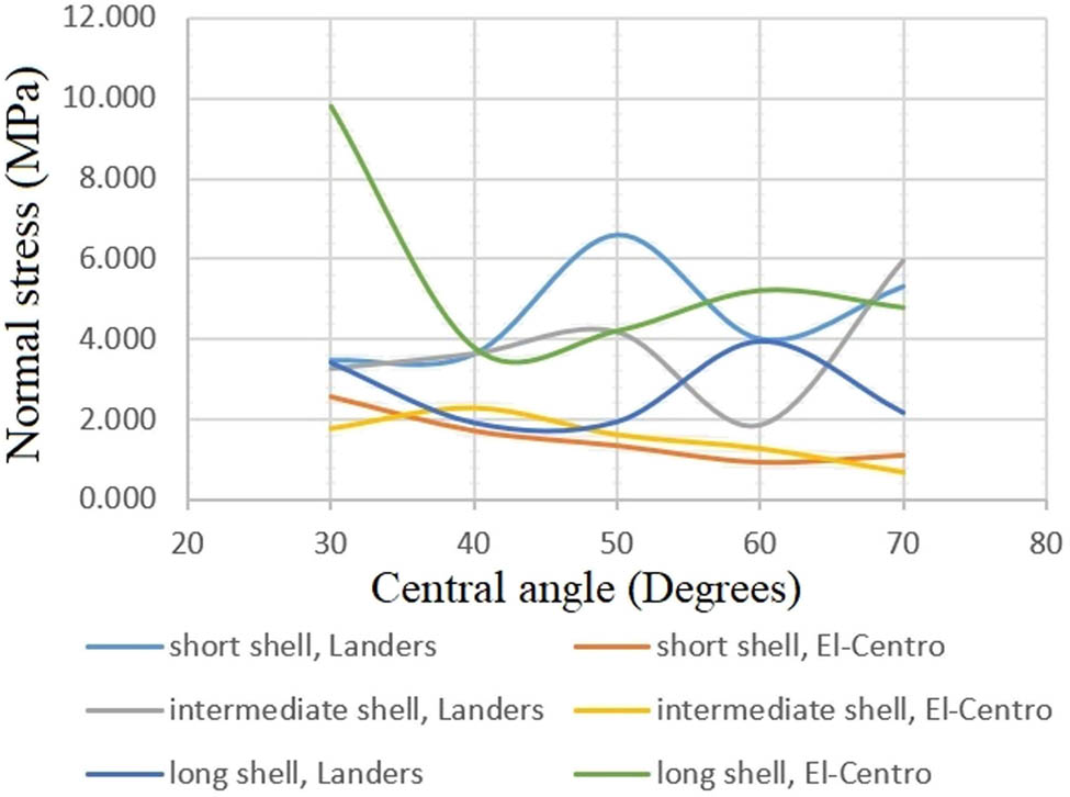
Maximum normal stresses with different central angles of shells, subjected to the vertical components of Landers and El-Centro earthquakes.
4 Discussion of parametric analysis
According to the response spectrum analyses, shells with a high fundamental frequency sustain lower structural damage from the studied earthquake loading because their behavior remains elastic. For an 8 cm-thick cylindrical shell, the effects of span on the fundamental frequency demonstrate that certain shells have a lower seismic risk than others due to these higher frequencies. The shapes of shells with smaller spans have higher fundamental frequencies, so their structural modes are less excited by seismic action than those with comparable forms but larger spans (Figure 5). Under horizontal and vertical earthquake excitations, 8 cm-thick shells with small to medium spans (up to 20 m) will behave entirely elastically. In addition to their high fundamental frequencies, their stiffness and mass play a role in determining their fundamental frequencies. Due to their lightweight design, yet stiffness due to their curved geometry, these shells are not at risk of damage during an earthquake.
The larger spans of reinforced concrete shells have a lower fundamental frequency; hence, they are more vulnerable to earthquake damage. The cylindrical reinforced concrete shells with spans of 20 m and thicknesses of 8 cm are relatively resistant to earthquake damage. In most earthquakes, the horizontal components are critical, making this finding important. However, these shells are at risk of damage from vertical seismic components. Interestingly, the relatively shallow shells presented in this article are more affected by vertical earthquake loading than by horizontal, in-plane earthquake loading. Insufficient rise can cause stresses induced by vertical earthquakes to exceed the concrete maximum tensile stress, resulting in cracking and a reduction in stiffness.
It is possible to increase the shell’s fundamental frequency to ensure its elastic behavior under this vertical excitation. Fundamental frequency can be most effectively impacted by changing the shape of the shell. In fact, increasing the curvature of cylindrical shells reduces the stress and deformation response to vertical excitation. Frequency increases almost linearly when the central angle increases from 30 to 70°. Overall, increasing fundamental frequencies and reducing deformations of these shells are best achieved by increasing their stiffness through curvature and thickness of the shell. The fundamental frequency is less affected by changing the shell thickness.
5 Conclusions
A set of reinforced concrete roof shells with a short, square, and long plan is analyzed under earthquake loading. Using cylindrical shells with different spans, this study compares and contrasts fundamental frequencies as well as deformations and stresses for El-Centro, as well as a particularly strong earthquake with a severe vertical component (Landers).
When subjected to either the horizontal or vertical components of the considered ground motions, 8 cm-thick shells with concrete compressive strength of 30 MPa are shown to exhibit elastic behavior as the permissible compressive and tensile strengths are never exceeded in the considered cases. Furthermore, shells with a span of 30 m or more are unlikely to sustain structural damage as a result of the considered seismic actions. As a result of their high stiffness and lightweight nature, these shells exhibit superior structural behavior. Consequently, the examined earthquakes, which mostly trigger lower frequency modes, only slightly affect the shell structural modes due to these characteristics.
Additionally, it is shown that the ultimate tensile stresses in these concrete shells and a span of 20 m can be exceeded by earthquakes with vertical components, which are more common during near-field earthquakes. By increasing the rise and thickness of these shells, the fundamental frequency can be increased, thereby reducing deformations and tensile stresses in the shells, again ensuring elastic response.
Despite the fact that shape and span have a significant impact on the earthquake resistance of concrete roof shells, the proper shape might not be sufficient during certain disastrous seismic events. It is also possible for nearfield seismic events with a high-frequency content or earthquakes with a strong vertical component to cause structural damage. It is important to consider other seismic protection measures beyond shell shape in areas where such seismic events are likely to occur. Shells commonly transfer loads to the ground through a limited number of supports, so base isolation of the supports could be an effective seismic protection measure.
-
Conflict of interest: The authors state no conflict of interest.
-
Data availability statement: Most datasets generated and analyzed in this study are included in this manuscript. The other datasets are available on reasonable request from the corresponding author with the attached information.
References
[1] Billington DP. Thin shell concrete structures. USA: McGraw-Hill College; 1982.Search in Google Scholar
[2] Isler H. Concrete shells derived from experimental shapes. Struct Eng Int. 1994;4(3):142–7.10.2749/101686694780601935Search in Google Scholar
[3] Garlock MEM, Billington DP, Burger N. Félix Candela: Engineer, Builder, Structural Artist. NJ: Princeton University Art Museum Princeton; 2008.Search in Google Scholar
[4] Jawad D. Nonlinear finite element analysis of reinforced concrete cylindrical shells. Basrah J Eng Sci. 2015;15(1):86–97.Search in Google Scholar
[5] Ballesteros P. Nonlinear dynamic and creep buckling of elliptical paraboloidal concrete shells. Bull Int Assoc Shell Spat Struct. 1978;66:39–60.Search in Google Scholar
[6] Scordelis A. Analysis of thin roof shells. Bull Int Assoc Shell Spat Struct. 1985;87:5–19.Search in Google Scholar
[7] Arnold C, Bolt B, Dreger D, Elsesser E, Eisner R, Holmes W, et al. Designing for earthquakes: A manual for architects. Mimari Tasarımda Deprem Fema. 2006;454.Search in Google Scholar
[8] Adriaenssens S, Ney L, Bodarwe E, Williams C. Finding the form of an irregular meshed steel and glass shell based on construction constraints. J Archit Eng. 2012;18(3):206–13.10.1061/(ASCE)AE.1943-5568.0000074Search in Google Scholar
[9] Adriaenssens S, Block P, Veenendaal D, Williams C. Shell structures for architecture: Form finding and optimization. Routledge Taylor & Francis Group; 2014.10.4324/9781315849270Search in Google Scholar
[10] Sasaki M. Structural design of free-curved RC shells: an overview of built works. Shell Struct Architecture. 2014;1:259–70.Search in Google Scholar
[11] Michiels T, Adriaenssens S. Identification of key design parameters for earthquake resistance of reinforced concrete shell structures. Eng Struct. 2017;153:411–20.10.1016/j.engstruct.2017.10.043Search in Google Scholar
[12] ANSYS. Workbench User’s Guide 2021 R2R2- ANSYS, Inc. and its subsidiaries and affiliates.Search in Google Scholar
[13] Adheem AH. Nonlinear analysis of reinforced concrete beams strengthened in shear with NSM FRP rods. J Babylon Univ/Eng Sci. 2013;21(1):160–73.Search in Google Scholar
[14] Musmar M, Rjoub M, Hadi M. Nonlinear finite element analysis of shallow reinforced concrete beams using SOLID65 element. Elastic. 2006;25743:0–3.Search in Google Scholar
[15] Lanczos C. An iteration method for the solution of the eigenvalue problem of linear differential and integral operators. National Bureau of Standards. 1950;45(4):255–82.10.6028/jres.045.026Search in Google Scholar
[16] Wilson EL, Der Kiureghian A, Bayo E. A replacement for the SRSS method in seismic analysis. Earthq Eng & Struct Dyn. 1981;9(2):187–92.10.1002/eqe.4290090207Search in Google Scholar
[17] Ostovari Dailamani S. Behaviour of cylindrical and doubly-curved shell roofs under earthquake. London, England: UCL (University College London); 2010.Search in Google Scholar
[18] Arnout S, Lombaert G, Degrande G, De Roeck G. The optimal design of a barrel vault in the conceptual design stage. Comput Struct. 2012;92:308–16.10.1016/j.compstruc.2011.10.013Search in Google Scholar
[19] Jarallah HK. Effects of coupling between lateral and torsional motions in seismic response of buildings. Basrah J Eng Sci. 2018;18(1):15–30.10.33971/bjes.18.1.3Search in Google Scholar
© 2023 the author(s), published by De Gruyter
This work is licensed under the Creative Commons Attribution 4.0 International License.
Articles in the same Issue
- Regular Articles
- Design optimization of a 4-bar exoskeleton with natural trajectories using unique gait-based synthesis approach
- Technical review of supervised machine learning studies and potential implementation to identify herbal plant dataset
- Effect of ECAP die angle and route type on the experimental evolution, crystallographic texture, and mechanical properties of pure magnesium
- Design and characteristics of two-dimensional piezoelectric nanogenerators
- Hybrid and cognitive digital twins for the process industry
- Discharge predicted in compound channels using adaptive neuro-fuzzy inference system (ANFIS)
- Human factors in aviation: Fatigue management in ramp workers
- LLDPE matrix with LDPE and UV stabilizer additive to evaluate the interface adhesion impact on the thermal and mechanical degradation
- Dislocated time sequences – deep neural network for broken bearing diagnosis
- Estimation method of corrosion current density of RC elements
- A computational iterative design method for bend-twist deformation in composite ship propeller blades for thrusters
- Compressive forces influence on the vibrations of double beams
- Research on dynamical properties of a three-wheeled electric vehicle from the point of view of driving safety
- Risk management based on the best value approach and its application in conditions of the Czech Republic
- Effect of openings on simply supported reinforced concrete skew slabs using finite element method
- Experimental and simulation study on a rooftop vertical-axis wind turbine
- Rehabilitation of overload-damaged reinforced concrete columns using ultra-high-performance fiber-reinforced concrete
- Performance of a horizontal well in a bounded anisotropic reservoir: Part II: Performance analysis of well length and reservoir geometry
- Effect of chloride concentration on the corrosion resistance of pure Zn metal in a 0.0626 M H2SO4 solution
- Numerical and experimental analysis of the heat transfer process in a railway disc brake tested on a dynamometer stand
- Design parameters and mechanical efficiency of jet wind turbine under high wind speed conditions
- Architectural modeling of data warehouse and analytic business intelligence for Bedstead manufacturers
- Influence of nano chromium addition on the corrosion and erosion–corrosion behavior of cupronickel 70/30 alloy in seawater
- Evaluating hydraulic parameters in clays based on in situ tests
- Optimization of railway entry and exit transition curves
- Daily load curve prediction for Jordan based on statistical techniques
- Review Articles
- A review of rutting in asphalt concrete pavement
- Powered education based on Metaverse: Pre- and post-COVID comprehensive review
- A review of safety test methods for new car assessment program in Southeast Asian countries
- Communication
- StarCrete: A starch-based biocomposite for off-world construction
- Special Issue: Transport 2022 - Part I
- Analysis and assessment of the human factor as a cause of occurrence of selected railway accidents and incidents
- Testing the way of driving a vehicle in real road conditions
- Research of dynamic phenomena in a model engine stand
- Testing the relationship between the technical condition of motorcycle shock absorbers determined on the diagnostic line and their characteristics
- Retrospective analysis of the data concerning inspections of vehicles with adaptive devices
- Analysis of the operating parameters of electric, hybrid, and conventional vehicles on different types of roads
- Special Issue: 49th KKBN - Part II
- Influence of a thin dielectric layer on resonance frequencies of square SRR metasurface operating in THz band
- Influence of the presence of a nitrided layer on changes in the ultrasonic wave parameters
- Special Issue: ICRTEEC - 2021 - Part III
- Reverse droop control strategy with virtual resistance for low-voltage microgrid with multiple distributed generation sources
- Special Issue: AESMT-2 - Part II
- Waste ceramic as partial replacement for sand in integral waterproof concrete: The durability against sulfate attack of certain properties
- Assessment of Manning coefficient for Dujila Canal, Wasit/-Iraq
- Special Issue: AESMT-3 - Part I
- Modulation and performance of synchronous demodulation for speech signal detection and dialect intelligibility
- Seismic evaluation cylindrical concrete shells
- Investigating the role of different stabilizers of PVCs by using a torque rheometer
- Investigation of high-turbidity tap water problem in Najaf governorate/middle of Iraq
- Experimental and numerical evaluation of tire rubber powder effectiveness for reducing seepage rate in earth dams
- Enhancement of air conditioning system using direct evaporative cooling: Experimental and theoretical investigation
- Assessment for behavior of axially loaded reinforced concrete columns strengthened by different patterns of steel-framed jacket
- Novel graph for an appropriate cross section and length for cantilever RC beams
- Discharge coefficient and energy dissipation on stepped weir
- Numerical study of the fluid flow and heat transfer in a finned heat sink using Ansys Icepak
- Integration of numerical models to simulate 2D hydrodynamic/water quality model of contaminant concentration in Shatt Al-Arab River with WRDB calibration tools
- Study of the behavior of reactive powder concrete RC deep beams by strengthening shear using near-surface mounted CFRP bars
- The nonlinear analysis of reactive powder concrete effectiveness in shear for reinforced concrete deep beams
- Activated carbon from sugarcane as an efficient adsorbent for phenol from petroleum refinery wastewater: Equilibrium, kinetic, and thermodynamic study
- Structural behavior of concrete filled double-skin PVC tubular columns confined by plain PVC sockets
- Probabilistic derivation of droplet velocity using quadrature method of moments
- A study of characteristics of man-made lightweight aggregate and lightweight concrete made from expanded polystyrene (eps) and cement mortar
- Effect of waste materials on soil properties
- Experimental investigation of electrode wear assessment in the EDM process using image processing technique
- Punching shear of reinforced concrete slabs bonded with reactive powder after exposure to fire
- Deep learning model for intrusion detection system utilizing convolution neural network
- Improvement of CBR of gypsum subgrade soil by cement kiln dust and granulated blast-furnace slag
- Investigation of effect lengths and angles of the control devices below the hydraulic structure
- Finite element analysis for built-up steel beam with extended plate connected by bolts
- Finite element analysis and retrofit of the existing reinforced concrete columns in Iraqi schools by using CFRP as confining technique
- Performing laboratory study of the behavior of reactive powder concrete on the shear of RC deep beams by the drilling core test
- Special Issue: AESMT-4 - Part I
- Depletion zones of groundwater resources in the Southwest Desert of Iraq
- A case study of T-beams with hybrid section shear characteristics of reactive powder concrete
- Feasibility studies and their effects on the success or failure of investment projects. “Najaf governorate as a model”
- Optimizing and coordinating the location of raw material suitable for cement manufacturing in Wasit Governorate, Iraq
- Effect of the 40-PPI copper foam layer height on the solar cooker performance
- Identification and investigation of corrosion behavior of electroless composite coating on steel substrate
- Improvement in the California bearing ratio of subbase soil by recycled asphalt pavement and cement
- Some properties of thermal insulating cement mortar using Ponza aggregate
- Assessment of the impacts of land use/land cover change on water resources in the Diyala River, Iraq
- Effect of varied waste concrete ratios on the mechanical properties of polymer concrete
- Effect of adverse slope on performance of USBR II stilling basin
- Shear capacity of reinforced concrete beams with recycled steel fibers
- Extracting oil from oil shale using internal distillation (in situ retorting)
- Influence of recycling waste hardened mortar and ceramic rubbish on the properties of flowable fill material
- Rehabilitation of reinforced concrete deep beams by near-surface-mounted steel reinforcement
- Impact of waste materials (glass powder and silica fume) on features of high-strength concrete
- Studying pandemic effects and mitigation measures on management of construction projects: Najaf City as a case study
- Design and implementation of a frequency reconfigurable antenna using PIN switch for sub-6 GHz applications
- Average monthly recharge, surface runoff, and actual evapotranspiration estimation using WetSpass-M model in Low Folded Zone, Iraq
- Simple function to find base pressure under triangular and trapezoidal footing with two eccentric loads
- Assessment of ALINEA method performance at different loop detector locations using field data and micro-simulation modeling via AIMSUN
- Special Issue: AESMT-5 - Part I
- Experimental and theoretical investigation of the structural behavior of reinforced glulam wooden members by NSM steel bars and shear reinforcement CFRP sheet
- Improving the fatigue life of composite by using multiwall carbon nanotubes
- A comparative study to solve fractional initial value problems in discrete domain
- Assessing strength properties of stabilized soils using dynamic cone penetrometer test
- Investigating traffic characteristics for merging sections in Iraq
- Enhancement of flexural behavior of hybrid flat slab by using SIFCON
- The main impacts of a managed aquifer recharge using AHP-weighted overlay analysis based on GIS in the eastern Wasit province, Iraq