Research of dynamic phenomena in a model engine stand
-
Derbiszewski Bogdan


Abstract
The highest loads on the elements of the crank–piston system of the internal combustion engine occur during the combustion phase which takes place successively in individual cylinders. Smaller, but also significant, loads occur beyond this phase when dynamic forces begin to play a dominant role. The latter depends on the degree of wear of the engine components. The aim of this article was to analyze the stresses in a model stand for testing dynamic phenomena in an internal combustion engine operating without the combustion process. A stand has been developed which includes a combustion engine driven by an electric motor placed on a mobile frame. The coast-down method was used to estimate the average values of the equivalent moment of inertia of the engine for various cylinder configurations with a lack of compression process due to a significant weakening of the valve springs or significant wear of the valve seats. This lack of compression was simulated on a bench by partially loosening the spark plug mounting. The article presents the values of the determined mean values of the equivalent moment of inertia of the engine and the stress values in the stand frame obtained from its model developed with the use of the finite element method. The obtained values were important from the point of view of the engine dynamics simulation process outside the combustion area and the safe foundation and operation of the stand frame during the experimental tests.
1 Introduction
It is commonly known that in various compression ignition and spark ignition combustion engines, piston compressors, and pumps, a slider–crank mechanism is used to convert a rotary motion into a linear motion or vice versa [1]. Their kinematic structure is constituted to transmit the full power from the piston to the crankshaft side and vice versa. The journal bearings are often applied to deal with the high loads transmitted through the system, limiting the possibility of a compact and hermetic solution [2,3].
Nigus [4] numerically formulated the kinematics of components of an internal combustion engine crank mechanism, the forces acting on the crank mechanism, and the torque applied based on the angles of the crank and connecting rod.
Cavalca [5] proposed a mathematical model for the dynamics of the slider-connecting rod–crank system interacting with the lubrication phenomenon in bearings with alternating motion. Such a model included two sub-models. The first one, based on the Eksergian equation of motion, represented the system when the connecting rod end was in contact with the rigid bearing surface without clearance. The second one, based on the Lagrange method, represented the system when the connecting rod end was in the hydrodynamic lubrication mode in the slider bore clearance. In this condition, the slider moves with the connecting rod, presenting a problem of multi-degrees of freedom.
Several studies focused on the dynamic analysis of such a system, considering the relative motions of its components and loads acting on its joints.
Varedi et al. [6] studied the effect of the clearances in the joints on the dynamics of such a system and proposed an optimization of the mass distribution of the links of a mechanism to reduce or eliminate the impact forces in the clearance joint.
Using 3D simulation software, Han [7] studied the effect of clearance joints of various materials on the dynamic characteristics of the slider–crank mechanism.
Xiao et al. [8] numerically studied the dynamic behavior of the slider–crank mechanism with clearance fault. They found that the displacement and velocity response of the slider–crank mechanism depended on the clearance in a weak way, while the acceleration response of the mechanism depended on it in a significant manner. With the existence of the clearance, the revolute joint of the mechanism generated rub–impact, and the greater the clearance, the higher the impact strength. During the rub–impact process, three kinds of motion states, separation, collision, and contact, were observed.
Cheng et al. [9] elaborated a flexible multi-body system dynamics model of the crank system to model the crank in an internal-combustion engine accurately. The film hydrodynamics model was built up by linking ADAMS software and elasticity hydrodynamics subroutines. Coupling analysis between multi-flexible body system dynamics and hydrodynamic lubrication of the crank system is processed. This model allowed analyzing the effects of pressure, temperature, rotating speed, and load on the locations of journal centers.
Yaqubi et al. [10] studied the possibility of enhancing the performance by using clearance control in joints accompanied by a second actuator on the connecting rod to reduce the vibrations and load on the first actuator.
Yan and Chen [11] applied a stepper motor to step away from the traditional trajectories associated with a constant speed input. By properly designing the input speed of the mechanism, its output motion can pass through a desired trajectory. A similar strategy was utilized by Yan and Yan [12] and Yan and Soong [13] for a four-bar mechanism.
Some studies focused on adequate actuation and torque control strategies to obtain a desired output profile [14,15].
Wang and Sarlashkar [16] presented algorithms recognizing and tracking the engine crankshaft position for arbitrary cam- and crankshaft tooth wheel patterns in both steady-state and transient operating conditions. This is valuable for prototyping engine control systems.
The use of adjustable slider–crank mechanisms was also studied to obtain typical trajectories [17,18].
Beckers et al. [19] experimentally evaluated the local linear actuating principle to obtain a continuous movement of the slider mechanism loaded with a spring–damper element where the top dead center and bottom dead center are reached and to minimize the loads transmitted through the mechanical structure. They found that by matching the operating frequency and resonance frequency of the system, a decrease of the loads transmitted through the system by 63% of the nominal spring load can be obtained.
Goudas et al. [20] investigated the dynamic behavior of slider–crank mechanisms with flexible supports and by driving the resisting loads affected by the angular coordinate of the crank rotation.
Alternatively, Sarigecili and Akcali [21] obtained a constant output force on the slider, independent of the crank angle, by adding a second (controlled) input force on the crank-connecting rod joint.
Soong designed the flexible linkage mechanisms with a rotational input and a linear input combined [22] and similarly, in Soong [23], where such a configuration was applied in a hybrid-driven mechanical press.
Beckers et al. [1] proposed linear actuation of the slider of a slider–crank mechanism, without a rotational input. This allowed providing the full power to the linear component directly to counteract the loads, instead of providing it rotationally and fully transmitted through the mechanical system. Such a configuration allowed for minimizing the loads in the joints and decreasing the power transmitted through the system significantly, compared to the other solutions [11,22,23]. Additionally, this allowed for the downsizing of the mechanical structure. The imposing of any desired trajectory and associated control strategies under the existing mechanical limits is also allowed. Maintaining such a mechanical link increased failure safety if an excessive force is imposed on the slider component, through simplified control strategies compared to, e.g., free piston compressors [24].
Currently, one of the directions of development of internal combustion engines is the use of a strategy of variable compression ratio, which can be achieved, inter alia, by stepwise or continuously changing the configuration of the crank system [25,26,27,28,29]. In order to be able to assess the impact of such a change on the inertia forces generated during engine operation, it is necessary to conduct tests on a test bench with a known course of such forces as a function of the engine speed, rotational speed and possibly also its angular acceleration, in the event of the occurrence of torsional vibrations of the crankshaft.
One combustion engine with the possibility of making changes in its crank mechanism (e.g., via changes of counterweight masses, use of connecting rods of controlled variable length) can be used for such studies. Particularly, this engine together with a driving electric motor is seated on a common frame of the test stand.
The conditions that the structure of the frame of the model engine stand should meet include the following:
providing a rigid structure that allows the drive to be transmitted in a safe and controlled manner,
using durable fasteners that enable stable restraint of the internal combustion engine and the electric motor,
applying vertical and horizontal adjustment of motors to level and align the drive shaft,
ensuring the mobility of structures for easy transport to different classrooms,
the use of road wheel locks preventing the structure from moving during the exercise,
protection of the structure against corrosion, and
construction cost at an acceptable level.
There are many solutions available in the market that enable the mounting of the combustion engine, e.g., workshop cranes, trolleys for servicing internal combustion engines, gantry winches, or engine dynamometers, but none of the designs meets all the assumptions.
The only solution was to design and build the frame to meet all the requirements. It was decided to make a welded structure of closed, cold-bent profiles with a rectangular cross section. To ensure the horizontal adjustment of the drive unit, eccentric holes are used. On the other hand, it is vertical adjustment, threaded rods cooperating with nuts, acting as jacks. The mobility of the structure was ensured by road wheels, which were able to carry a high dynamic load.
However, for the design of the structure, data on the load that acts on it were necessary. These loads include static loads due to gravity, dynamic loads due to the torque of the electric motor, and dynamic loads due to the movement of the crank–piston system of the combustion engine. While the first two load cases were relatively easy to determine, those from the crank–piston system became problematic.
The most important forces acting on the crank system are the forces generated by the gas pressure and the inertia force. In this case, the forces resulting from the gas pressure were neglected, as the stand is intended for testing an engine without compression.
Numerous publications on internal combustion engines deal with the dynamics of the crank–piston system [30,31,32,33,34,35,36]. They describe the method of determining the forces acting on the crank system, including the inertia forces. It turns out that the forces of inertia can be determined straightforwardly, but to do this, it is necessary to know the dimensions and masses of all elements of the crank–piston system. Additionally, each internal combustion engine is balanced at the design stage to balance the forces of the system.
Due to the lack of data on the dimensions and masses of the elements of the crank system and the lack of knowledge about the degree of balance of the considered engine, it was impossible to use the mathematical model described in the literature. Therefore, it was necessary to use a substitute dynamic model.
Various engine stands can be used for the exposition of combustion engines [37] or their repairs [38,39].
Various engine test stands of various complexity levels are also available in the market [40,41]. However, due to costs and individual requirements as to the equipment of a specific stand and the conditions for conducting tests on such a stand, such test stands are made individually. For example, such stands can be made to order according to the developed technological documentation, taking into account, inter alia, the requirements of safe operation during testing (e.g., protection of people against being hit by rotating parts, or electric arc shock, through the use of appropriate shields, individual protective measures, designation of a safe zone) and minimizing the negative impact on the environment (e.g., due to the high level of generated vibrations, noise, emission of solid particles, and exhaust gases). The research stand under analysis belonged to the group of individually designed ones.
The goal of the present study was to
estimate the moment of inertia of the crank–piston system, and
additionally analyze the stresses in a research stand for testing dynamic phenomena in an internal combustion engine operating without the combustion process.
2 Materials and methods
2.1 Research stand studied
The research stand studied (Figure 1) comprised a combustion engine operated without the combustion process. The crankshaft of such an engine was driven by an electric motor linked via the driving shaft connected with elastic coupling. An electric motor was fixed to the common frame using the mounting screws. A combustion engine was mounted on the threaded brackets welded to the frame. The position of the motor could to some extent be varied vertically with these brackets and fixed through fixing nuts. The frame was connected to swivel wheels fitted with solid rubber tires mounted horizontally in brackets. The latter were able to rotate fully about their vertical axes. As a result, the frame could be moved horizontally across the ground with sliding and rotary movements. Simple lever brakes made it possible to block individual wheels, which stabilized the position of the frame during the tests.

The tested engine stand.
The combustion engine utilized in the research stand was an Opel Corsa C engine with the basic parameters presented in Table 1.
Basic parameters of the tested internal combustion engine
| Type | Ignition | Cylinder numbers | Displacement (dm3) | Power (kW) |
|---|---|---|---|---|
| 1.2XE | Spark | 4 | 1.2 | 55 |
This possibility of changing the position of the engine with the abovementioned brackets made it possible to adjust the coaxiality of the crankshaft of the engine and the rotor of the electric motor. Moreover, other tests on the stand are also possible, e.g, tests of the influence of the axle misalignment of the rotating elements on the physical phenomena occurring in the flexible coupling or the joint connecting the electric motor rotor with the crankshaft of the internal combustion engine. When determining the average moment of inertia of the piston and crank system of the internal combustion engine, the effect of air compression in the internal combustion engine cylinders was practically eliminated by removing the spark plugs, as mentioned in the previous section.
2.2 Static loads of the frame analyzed
As mentioned earlier, the drive unit consisted of an electric motor, a combustion engine, and a drive shaft. Each of these elements generates a load on the frame by gravity. After weighing all the elements and determining the center of gravity of the assembly consisting of the electric motor and the shaft, it was possible to calculate the static load acting on the frame (Figure 2).
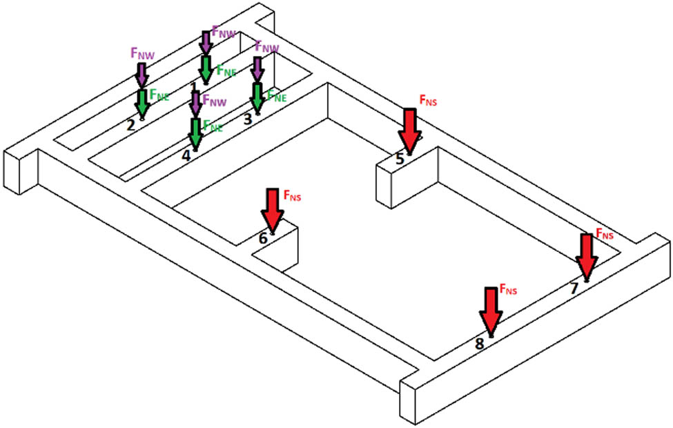
Static loads acting on the frame.
The gravity forces from the electric motor were determined using equation (1). It was assumed, to simplify calculations, that the single force is just one-fourth of the weight of all electric motors:
The gravity forces from the combustion engine were determined using the following equation:
The force of gravity from the drive shaft with coupling was determined using the following equation:
For simplicity of calculations, it was assumed that the F NW forces are acting in the same places as F NS. Such an assumption did not introduce too much error, as the center of gravity for the electric motor is shifted related to the center of the set of screws mounting the motor to the frame. Therefore, compensation to some extent has appeared between the moments from the electric motor weight and from the drive shaft with coupling.
2.3 Dynamic load from the torque of the electric motor
The torque generated by the electric motor acts on the power unit mounting lugs with an unknown force. However, with the data given on the nameplate, it was possible to read the rated power and rotational speed (Figure 3).

Electric motor nameplate.
Using the above data, the torque (M obr) of the electric motor was estimated from the following equation:
where P is the power of the electric motor (W), ω is the angular velocity (rad/s), M obr is the torque (Nm), and n is the rotation speed (rpm).
Knowing the value of the torque, it was possible to determine the force value transmitted by the structure. Knowing the location of all fasteners, such a value was determined from the following equation (Figure 4):
where z max is the highest distance of the clamping from the axis of rotation along the Z-axis (mm) and ΣZ i is the sum of all mounting distances from the axis of rotation along the Z-axis (mm).
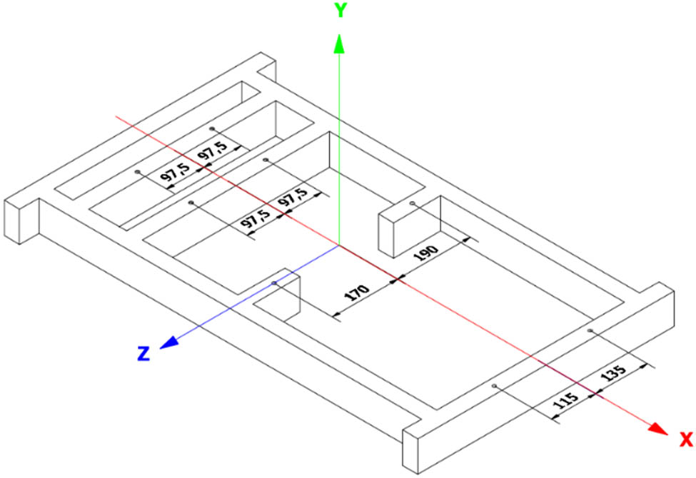
Arrangement of fasteners in relation to the Z-axis.
A rotating motor will cause compression on some mounts and tension on others, as can be seen in Figure 5.

Dynamic load due to the torque of the electric motor acting on the structure.
2.4 A dynamic equivalent model used for determining the dynamic load from the crank–piston system inertia
It was assumed that the sum of the inertia moments of the rotor of the asynchronous electric motor [42] and of the driveshaft [43] with elastic coupling [44,45] was much lower than the inertia moment of the crank–piston system.
To determine the equivalent dynamic model, the dynamic equation for the rotational motion of a system comprising rigid bodies was used. A temporary change in the moment of inertia of the crank–piston system of an internal combustion engine was achieved with an additional rotating mass with a known moment of inertia almost coaxially with the engine crankshaft. The moment of inertia was changeable, i.e., through a system of several interchangeable identical concentric rings. During studies, the system was mounted either by screwing a set of rings to additional holes made in the flywheel or by mounting the set near the flywheel on the previously made cylindrical surface of the drive shaft with coupling. The dynamic equation for the crank–piston system without additional inertial rings took a form (6), while for the case with the additional rings it took a form (7):
where M T1 is the average torque of the resistance to motion for the crank–piston system without additional inertial rings (Nm), M T2 is the average torque of the resistance to motion for the crank–piston system with additional inertial rings (Nm), I 1 is the moment of inertia of the crank–piston system of the combustion engine (kg m2), ε 1 is the angular acceleration of the internal combustion engine without the load (rad/s2), I 2 is the moment of inertia with additional inertial rings installed in the crank–piston system (kg m2), and ε 2 is the angular acceleration of the combustion engine with additional inertial rings (rad/s2).
It was assumed that the average torque values of the resistance to motion for the crank–piston system without (M T1) and with additional inertial rings (M T2) are close to each other, the condition of which could be written in the form (7). The torque of the resistance to motion for the crank–piston system of the combustion engine without the combustion process was composed of three parts [46]:
The reciprocating inertia torque is generated by the reciprocating part of the connecting rod system. Reciprocating mechanisms have variable inertia due to the change in the geometry through a crank revolution [47]. The average values and the range of variability of such a torque were practically the same for each measuring series, as no relative moving part of the engine was changed during measurements.
The friction torque resulted from the piston group (about 50%), main bearings and big-end bearings (about 30%), and valvetrain including crankshaft seals and timing drive (about 20%) [48]. The values of this torque were affected by the temperature; the engine speed and the kind of lubricating oil were fixed, as the measurements were conducted at room temperature, the same initial value, the range of engine speed caused by the electric motor driving its crankshaft, and the original engine oil.
The brake torque was practically excluded via dismantling the spark plugs. The holes in the cylinder head exposed to the atmosphere were connected via plastic hoses with plastic containers, which allowed for the collection of oil droplets sprayed out of these holes when rotating the crankshaft of the engine driven by the electric motor.
Based on the above comments, we adopted the assumption of the equality of the torques M T1 and M T2.
From equations (5)–(7), formula (8) was derived that allowed the calculation of the moment of inertia of the engine crank–piston system:
This means that if
the additional inertial rings on the crank–piston system are used, the moment of inertia of the inertial rings can be determined,
two values of time in which the engine accelerates (or decelerates) separately with and without inertial rings are measured, the average moment of inertia of the crank–piston system can be determined.
2.5 Determination of the moment of inertia of the additional inertial rings installed in the crank–piston system
The assembly of inertial rings attached to the crankshaft of the combustion engine comprises a subassembly of six steel discs with a total weight of 6.41 kg and a steel bushing weighing 0.26 kg. The dimensions of such components are shown in Figure 6. It was necessary to use such a bushing, as the attachment of the assembly of inner rings to the crankshaft was made with an M14 bolt with an outer diameter of 14 mm; the inner radius of the cylinder was 38 mm.

Dimensions of additional rings mounted on the crankshaft system.
Since both a set of steel disks and sleeves form a hollow cylinder, their moments of inertia were determined using the following equation:
where m is the mass (kg), R z is the outer radius (mm), and R w is the inner radius (mm).
The moment of inertia of the steel bushing was estimated from the following equation:
The moment of inertia of the subassembly comprising six steel pulleys was estimated from the following equation:
The total moment of inertia was obtained from the following equation:
2.6 Determination of the angular acceleration of the motor with and without a load
The angular acceleration of the electric motor was also determined from the following equation:
where ω is the rated speed of the electric motor (rad/s), ω 0 is the initial speed, but in this case, ω 0 = 0 (rad/s), and t is the time at which acceleration/deceleration occurs (s).
The angular speed could be determined based on the engine speed data on the nameplate and using the following equation:
The only unknown was the time at which the electric motor accelerated. This time can be the one from the motor start until it reaches its rated speed. This means that this time could be easily determined based on measurements and the observation of selected geometric details, e.g., painted markings or characteristic cut-outs made in the material of the rotating rotor or crankshaft. The measurements were recorded using a camera, and the results were recorded using a tachograph giving the number of engine revolutions and a stopwatch (Figure 7).

Measuring apparatus: (a) laser tachometer and (b) digital stopwatch.
As there was a need to determine the angular acceleration of the motor both without and with the application of additional inertial rings, it became obvious that it was necessary to perform measurements for both cases. Moreover, to minimize the measurement error, a series of 20 measurements were performed for each case, based on which the mean value was determined.
2.7 Determination of the angular acceleration of the motor with and without a load
An analysis of stress distribution was also conducted in the frame affected by the static and dynamic loadings mentioned. Such an analysis was conducted using the finite element method implemented in Autodesk Inventor Professional software. The geometrical model of the frame was first elaborated when all weldings were created as solid volumes. Knowing the estimated values of loads acting on the frame, a rectangular profile 80 × 40 × 2 in accordance with the PN-EN10219-2:2019 standard was chosen for its structural components connected by welding. The required core of the threaded rod was chosen to be the one related to the M24 thread, as it provided enough resistance to compression and buckling loading. All components were treated as one elastic body. The grid of tetrahedral finite elements was generated automatically. Each element has four nodes, each of them possessing three degrees of freedom in the form of displacements u x , u y , u z along the X, Y, Z axes of the global coordinate system, respectively. The material model comprises parameters of stainless steel such as Young’s modulus with a value of 210,000 MPa and the Poisson number equal to 0.3. The cylindrical surface of holes where the four brackets related to the frame were fixed. The cylindrical holes for mounting screws fixing the electric motor to the frame and the upper top front planes of the threaded rod were loaded by the related resultant forces described in the previous sections. The analysis was conducted under steady-state conditions.
3 Results and discussion
The resulting values of the engine start-up time are presented in Table 2 for the case without additional inertia rings and those for the case with additional inertia rings are shown in Table 3.
Results of measurements of the engine start-up time without additional rings
| No. | 1 | 2 | 3 | 4 | 5 | 6 | 7 | 8 | 9 | 10 |
|---|---|---|---|---|---|---|---|---|---|---|
| t 1 (s) | 1.91 | 2.08 | 2.10 | 2.12 | 2.11 | 2.13 | 2.19 | 2.00 | 2.03 | 2.16 |
| No. | 11 | 12 | 13 | 14 | 15 | 16 | 17 | 18 | 19 | 20 |
|---|---|---|---|---|---|---|---|---|---|---|
| t 1 (s) | 2.09 | 2.19 | 2.18 | 2.00 | 2.05 | 2.19 | 2.12 | 1.97 | 2.02 | 2.03 |
| Mean value (s) | 2.08 | |||||||||
Note: t1 is the time the electric motor needs to accelerate from the start to reach the rated speed for the case without additional inertial rings (s).
Results of measurements of the engine start-up time with additional rings
| No. | 1 | 2 | 3 | 4 | 5 | 6 | 7 | 8 | 9 | 10 |
|---|---|---|---|---|---|---|---|---|---|---|
| t 2 (s) | 2.43 | 2.40 | 2.40 | 2.59 | 2.53 | 2.62 | 2.50 | 2.53 | 2.37 | 2.66 |
| No. | 11 | 12 | 13 | 14 | 15 | 16 | 17 | 18 | 19 | 20 |
|---|---|---|---|---|---|---|---|---|---|---|
| t 2 (s) | 2.68 | 2.59 | 2.75 | 2.50 | 2.69 | 2.59 | 2.60 | 2.40 | 2.41 | 2.69 |
| Mean value (s) | 2.55 | |||||||||
Note: t2 is the time the electric motor needs to accelerate from the start to reach the rated speed for the case with additional inertial rings (s).
Using the average values of time in which the motor is accelerating and the determined angular velocity values, we have obtained the average values of angular acceleration from equation (16) without additional inertia rings and from equation (17) with additional inertia rings:
From the determined values of the moment of inertia of the additional inertial rings and the angular acceleration values determined for the cases without and with such rings, the obtained average value of the moment of inertia of the crank–piston system of the combustion engine, using equation (18) based on equation (9):
The torque of the engine with an additional inertial ring was calculated from the following equation:
Then, using the previously determined mounting locations in Figure 4 and again using formula (5), it was possible to determine the values of the forces with which the load from the crank–piston system exerts on the frame, as presented by the following equation:
Such forces are presented in Figure 8.

Dynamic load from the crank–piston system acting on the frame.
After determining all the loads acting on the frame, both static and dynamic, it was possible to determine the resultant forces acting on a given fastening, using equations (21)–(24) (Figures 9 and 10):
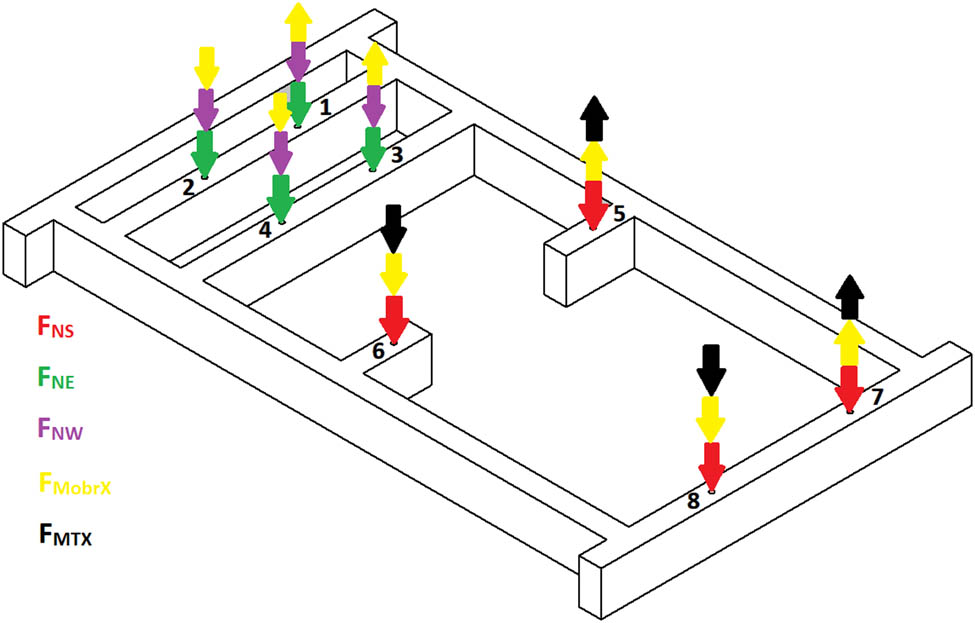
All loads acting on the structure.

The resultant forces acting on the frame.
The resulting distribution of von Mises stresses is shown in Figure 11. Their values did not exceed 36 MPa and were at least tenfold lower than the value of the yield stress for the stainless steel. The safety factor values obtained are presented in Figure 12. As their values were higher than 5.9, this provided the elevated level of safety of the frame loaded by static and dynamic forces generated during the operation of an electric motor driving a combustion engine on the research stand. The values of displacements of frame components along the Z direction being vertical are shown in Figure 13. They can cause deviation of the crankshaft axis from the horizontal plane by an angle of up to 0.024° and the rotor axis of the electric motor from the horizontal plane by an angle of up to 0.009°. The relatively high deflection of the brackets supporting the combustion engine from the side of the electric motor indicates the possibility of a large misalignment of the rotor of the electric motor and the crankshaft of the combustion engine and the necessity to use a flexible coupling and even a joint when connecting them through the drive shaft.

von Mises stresses determined.

Safety factors determined.

Displacement in the Z direction.
To verify the results of the measurements, the calculated average value of the moment of inertia for the combustion engine crankshaft–piston system was compared with those for combustion engines with similar parameters presented in the literature.
Miljic et al. [49], for their research, created a model of the rotating elements of the DV4TD 8HT engine produced by the PSA group, using CAD. According to the research results, the moment of inertia of the entire crankshaft–piston system with similar parameters was equal to
Moments of inertia of individual components of the DV4TD 8HT engine [49]
| Engine part name | Engine part mass (g) | Engine part moment of inertia (kg m2) |
|---|---|---|
| Crankshaft | 12,940 | 0.0192 |
| Flywheel | 7,960 | 0.0742 |
| Flywheel-drive shaft adapter | 2,800 | 0.0258 |
| Connecting rod mass reduced to the crankpin journal | 361.9 | 0.0024 (all four cylinders) |
| Inertia of the crankshaft mechanism oscillating parts | 0.0022 (all four cylinders) | |
| Poly – V pulley | 2,070 | 0.0069 |
| Total | 0.1307 | |
Pexa et al. [50] proposed an innovative method of evaluating the moment of inertia of the engine using loosely mounted shafts on which the vehicle wheels are guided. The acceleration of the car in the selected gear results in the transfer of torque to the shafts, which causes their rotation. Then, the electric motors connected to the shafts are turned on, which causes a continuous increase in the engine speed without the need to depress the accelerator. Based on these measurements, the instantaneous speed and acceleration waveforms are obtained, based on which it becomes possible to determine the moment of inertia of the engine (Table 5).
Moments of inertia of selected engines obtained by the method of loose shafts [50]
| Producer | Vehicle model | Year of production | Fuel type | Engine volume (dm3) | Power (kW) | Moment of inertia of the engine (kg m2) |
|---|---|---|---|---|---|---|
| Hyudai | i20 | 2008 | Gasoline | 1.2 | 57.2 | 0.0961 |
| Peugeot | 107 | 2008 | Gasoline | 1.0 | 50 | 0.0741 |
| Peugeot | 308 SW | 2008 | Diesel oil | 1.6 HDI | 80 | 0.2082 |
| Skoda | Octavia II | 2006 | Diesel oil | 2.0 TDI | 103 | 0.3152 |
| Skoda | Octavia II | 2004 | Gasoline | 2.0 FSI | 110 | 0.3293 |
| Skoda | Favorit | 1991 | Gasoline | 1.3 carburetor | 46 | 0.1317 |
| Skoda | Octavia | 2005 | Gasoline | 1.6 MPI | 75 | 0.1882 |
| Skoda | Room-ster | 2007 | Diesel oil | 1.4 TOI | 59 | 0.2619 |
| Skoda | Felicia | 1998 | Gasoline | 1.3 MPI | 50 | 0.1361 |
| Skoda | Felicia | 2000 | Gasoline | 1.4 Seort | 100 | 0.1556 |
These engines have very close parameters to the one studied.
The differences between the moment of inertia values obtained during tests presented in Pexa et al. [50] and the values obtained by the authors were found to be 2%.
Ubysz [51] used the Catia V5 computer program to create models of selected engines and, on their basis, determined the moments of inertia. Among them, there was a unit with the designation ZI 1.2XE. This is the same unit as the moment of inertia was calculated, hence it was a key publication for comparative analysis (Table 6).
Moments of inertia of motors obtained with Catia software [51]
| No. | Types of engines | Measured weight (kg) | Mass moment of inertia (kg m2) | |||||
|---|---|---|---|---|---|---|---|---|
| Crank shaft | Flywheel assembly | Connecting rod | Cranksshaft with connecting good | Flywheel assembly | Engines | |||
| Assembly | Rotational part | |||||||
| 0 | 1 | 2 | 3 | 4 | 5 | 6 | 7 | 8 |
| 1. | ZI 1.0 XE | 9.67 | 14.3 | 0.375 | 0.266 | 0.014 | 0.135 | 0.149 |
| 2. | ZI 1.2 XE | 10.05 | 11.3 | 0.375 | 0.266 | 0.015 | 0.110 | 0.125 |
| 3. | ZS 1.3 TDI | — | 15.0 | — | — | — | 0.145 | — |
| 4. | ZS 1.7 TDi | 16.72 | 12.94 | 0.707 | 0.505 | 0.027 | 0.152 | 0.179 |
| 5. | ZS 1.7 TDi | 16.72 | 17.50 | 0.707 | 0.505 | 0.027 | 0.184 | 0.211 |
| 6. | ZS 2.0 TDi | 15.43 | 18.13 | 0.701 | 0.505 | 0.027 | 0.219 | 0.246 |
Bold means that the inertial moments of components are close to those of engine on the research stand applied.
Comparing the calculated moment of inertia values with the values provided by Ubysz [51], a difference of 7% was obtained.
4 Conclusions
The following are the conclusions from the obtained results:
The average value of the moment of inertia for the crankshaft–piston system for the combustion engine analyzed has been determined experimentally on the elaborated research stand.
The use of an additional rotating mass with a known moment of inertia almost coaxially with the engine crankshaft allowed a temporary change in the moment of inertia of the crank–piston system of an internal combustion engine, similar to previous studies [52,53]. The measurement of the time of acceleration or deceleration of the crankshaft–piston assembly consecutively with and without the additional rotating mass allowed determining the average moment of inertia of the crankshaft–piston system.
The frame of the research stand can be safely loaded both from the weight of the combustion engine, electric motor, and driving shaft with coupling and from the dynamic loading from the electric motor torque and the periodically varying inertial torque of the combustion engine.
The elaborated research stand can be utilized for the determination of the moment of inertia for the crankshaft–piston system for combustion engines with similar parameters and characteristics operating without the combustion process.
Using the same or similar set of the combustion engine, electric motor, and driveshaft, the research stand can be used to study the effect of the axle misalignment of rotating elements on the physical phenomena occurring in the flexible coupling or the joint connecting the electric motor rotor with the crankshaft of the internal combustion engine.
The fact that the value of the moment of inertia obtained from calculations differed from those for similar combustion engines published in the literature in the range of 2–5% supports the correctness of the measurement results and the analytical method utilized in the present study.
Acknowledgements
The authors thank to The President Stanisław Wojciechowski State University of Applied Sciences in Kalisz for the partial financial support.
-
Conflict of interest: Authors state no conflict of interst.
References
[1] Beckers J, Verstraten T, Verrelst B, Contino F, Van Mierlo J. Analysis of the dynamics of a slider-crank mechanism locally actuated with an act-and-wait controller. Mechanism Mach Theory. 2021;159:104253. 10.1016/j.mechmachtheory.2021.104253.Suche in Google Scholar
[2] Liang K, Stone R, Hancock W, Dadd M, Bailey P. Comparison between a crank-drive reciprocating compressor and a novel oil-free linear compressor. Int J Refrig. 2014;45:25–34. 10.1016/j.ijrefrig.2014.05.022.Suche in Google Scholar
[3] Bailey P, Dadd M, Stone C. An oil-free linear compressor for use with compact heat exchangers. International Conference on Compressors and their Systems; 2009. p. 259–68.Suche in Google Scholar
[4] Nigus H. Kinematics and load formulation of engine crank mechanism. Mechanics Mater Sci Eng J Magnolithe. 2015:112–23. 10.13140/RG.2.1.3257.1928.Suche in Google Scholar
[5] Cavalca K. Analysis of the dynamics of a Slider–Crank mechanism with hydrodynamic lubrication in the connecting Rod–Slider joint clearance. Mech Mach Theory. 2011;46:1434–52. 10.1016/j.mechmachtheory.2011.05.007.Suche in Google Scholar
[6] Varedi S, Daniali H, Dardel M, Fathi A. Optimal dynamic design of a planar slider-crank mechanism with a joint clearance. Mech Mach Theory. 2015;86:191–200.10.1016/j.mechmachtheory.2014.12.008Suche in Google Scholar
[7] Han Y. Simulation and experimental study on dynamic response of crank-slider mechanism with clearance joints of different materials. Int J Eng Res Technol (IJERT). 2017;6(1):125–8.Suche in Google Scholar
[8] Xiao S, Song M, Zhang Z. Dynamic analysis of slider-crank mechanism with clearance fault. Vibroeng Procedia. 2019;29:12–7.10.21595/vp.2019.21103Suche in Google Scholar
[9] Cheng Y, Zhuang TS, Song X. Crank system coupling simulation between dynamics of flexible multi-body and hydrodynamic lubrication. SAE Technical Paper 2007-01-3484; 2007.10.4271/2007-01-3484Suche in Google Scholar
[10] Yaqubi S, Dardel M, Daniali HM. Nonlinear dynamics and control of crank–slider mechanism with link flexibility and joint clearance. Proc Inst Mech Eng, Part C: J Mech Eng Sci. 2016;230(5):737–55.10.1177/0954406215593773Suche in Google Scholar
[11] Yan H-S, Chen W-R. On the output motion characteristics of variable input speed servo-controlled slider-crank mechanisms. Mechan Mach Theory. 2000;35(4):541–61.10.1016/S0094-114X(99)00023-3Suche in Google Scholar
[12] Yan H-S, Yan G-J. Integrated control and mechanism design for the variable input-speed servo four-bar linkages. Mechatronics. 2009;19(2):274–85.10.1016/j.mechatronics.2008.07.008Suche in Google Scholar
[13] Yan H-S, Soong R-C. An integrated design approach of four-bar linkages with variable input speed. JSME Int J Ser C Mech Syst Mach Elem Manuf. 2004;47(1):350–62.10.1299/jsmec.47.350Suche in Google Scholar
[14] Wang X, Ma Q, Zhu Z. Low noise control of servo press. In IECON 2007 - 33rd Annual Conference of the IEEE Industrial Electronics Society; 2007. p. 833–8.10.1109/IECON.2007.4460337Suche in Google Scholar
[15] Ha J-L, Fung R-F, Chen K-Y, Hsien S-C. Dynamic modeling and identification of a slider-crank mechanism. J Sound Vib. 2006;289(4):1019–44.10.1016/j.jsv.2005.03.011Suche in Google Scholar
[16] Wang J, Sarlashkar J. Engine crankshaft position tracking algorithms applicable for given arbitrary cam- and crank-shaft position signal patterns. SAE Technical Paper 2007-01-1597; 2007. 10.4271/2007-01-1597.Suche in Google Scholar
[17] Shoup TE. The design of an adjustable, three dimensional slider crank mechanism. Mech Mach Theory. 1984;19(1):107–11.10.1016/0094-114X(84)90012-0Suche in Google Scholar
[18] Zhou H, Ting K-L. Adjustable slider–crank linkages for multiple path generation. Mech Mach Theory. 2002;37(5):499–509.10.1016/S0094-114X(02)00008-3Suche in Google Scholar
[19] Beckers J, Verrelst B, Contino F, Van Mierlo J. Experimental investigation of the dynamics of a slider-crank mechanism with local linear force input. ASME J Appl Mech. 2022;89(4):041002. 10.1115/1.4053146.Suche in Google Scholar
20 Goudas I, Stavrakis I, Natsiavas S. Dynamics of slider-crank mechanisms with flexible supports and non-ideal forcing. Nonlinear Dyn. 2004;35:205–27. 10.1023/B:NODY.0000027914.66360.01.Suche in Google Scholar
[21] Sarigecili MI, Akcali ID. Development of constant output–input force ratio in slider–crank mechanisms. Inverse Probl Sci Eng. 2019;27:565–88.10.1080/17415977.2018.1470625Suche in Google Scholar
[22] Soong R-C. A design approach for flexible linkage mechanisms with a rotational and a linear input. Adv Sci Lett. 2012;9:499–504.10.1166/asl.2012.2569Suche in Google Scholar
[23] Soong R-C. The new hybrid-driven mechanical presses. J Vibroeng. 2014;16:945–53.Suche in Google Scholar
[24] Liang K. A review of linear compressors for refrigeration. Int J Refrigeration-Revue Int Du Froid. 2017;84:253–73.10.1016/j.ijrefrig.2017.08.015Suche in Google Scholar
[25] Csaba C. Science Behind Infiniti’s Variable-Compression-Ratio Engine. Under pressure. 2017. https://www.caranddriver.com/features/g15084183/under-pressure-the-science-behind-infinitis-variable-compression-ratio-engine/(accessed on 13 April 2022).Suche in Google Scholar
[26] 4WD modifications -tech torque. Variable compression ratio engines. https://outbacktravelaustralia.com.au/4wd-mods-tech-torque/variable-compression-ratio-engines/(accessed on 13 April 2022).Suche in Google Scholar
[27] Wos P, Kuszewski H, Ustrzycki A. Exhaust emission features of variable compression ratio (VCR) diesel engine. J KONES. 2010;17(3):521–6.Suche in Google Scholar
[28] Lejda K, Wos P. A preliminary project of multi cylinder, variable compression ratio (VCR) engine for research purposes. Combust Engines SC2, PTNSS-2009-062. 2009;152–7.Suche in Google Scholar
[29] Shaik A, Shenbaga Vinayaga Moorthi N, Rudramoorthy R. Variable compression ratio engine: a future power plant for automobiles – an overview. Proceedings of the Institution of Mechanical Engineers (IMechE), Part D: Journal of Automobile Engineering. 2007;221(D9):1159–68.10.1243/09544070JAUTO573Suche in Google Scholar
[30] Davitashvili N, Bakhshaliev V. Dynamics of crank-piston mechanisms. Singapore: Springer; 2016. p. 242. 10.1007/978-981-10-0323-3.Suche in Google Scholar
[31] Perera R, Cheng S, Liu S. Dynamic analysis of slider-crank mechanism with a cracked rod. Math Probl Eng. 2018;8540546. 10.1155/2018/8540546.Suche in Google Scholar
[32] Cheng S, Liu S. Dynamic analysis of slider-crank mechanism with a cracked rod. Math Probl Eng. 2018;8540546:1–7. 10.1155/2018/8540546.Suche in Google Scholar
[33] Maldonado V, Chaynov N. Calculation of kinematics and dynamics of inline piston engines. ru: INFRA-M. Moscow, Russia: Academic Publishing LLC; 2021. 10.12737/1058850.Suche in Google Scholar
[34] Maldonado V, Ramon P, Chaynov N. Kinematics and dynamics of automobile piston engines. ru: INFRA-M. Moscow, Russia: Academic Publishing LLC; 2019. 10.12737/989072.Suche in Google Scholar
[35] Nassim K. Crank-slider mechanism of a piston. In Virtual reality and animation for MATLAB® and Simulink® Users. London: Springer London; 2011. p. 35–48. 10.1007/978-1-4471-2330-9_5.Suche in Google Scholar
[36] Mundo D, Gatti G, Danieli G, Dooner DB. Kinematic analysis of an adjustable slider-crank mechanism. In Computational kinematics. Berlin, Heidelberg: Springer Berlin Heidelberg; 2009. p. 257–64. http://dx.doi.org/10.1007/978-3-642-01947-0_32.Suche in Google Scholar
[37] Engine Basis. Engine Stand Reviews and evaluations. https://www.enginebasics.com/Product%20Tools/Engine_Stand.html (accessed on 14 June 2022).Suche in Google Scholar
[38] Christiansen C. Engine Stand. US3765667A; 1973.Suche in Google Scholar
[39] Hanger JE. Engine Stand. US4239196A; 1980.Suche in Google Scholar
[40] Acosta G “PRW Engine Test Stand Packs Big Function Into A Tiny Footprint”. 18 October 2018. Available online: https://www.enginelabs.com/engine-tech/prw-engine-test-stand-packs-big-function-into-a-tiny-footprint/(accessed on 14 June 2022).Suche in Google Scholar
[41] Easy-run Engine Test Run Stands. Available online: https://easy-run.com/(accessed on 14 June 2022).Suche in Google Scholar
[42] de Almeida A, Ferreira F, Ge B. Beyond induction motors – technology trends to move up efficiency. IEEE Trans Ind Appl. 2014;50:2103–14. 10.1109/TIA.2013.2288425.Suche in Google Scholar
[43] Industrial Driveshafts. Available online: https://medialibrary.dana-industrial.com/wp-content/uploads/IK_englisch_19.06.20.pdf (accessed on 14 June 2022).Suche in Google Scholar
[44] Shaft Coupling Ringspan Power Transmision, 2020. Available online: https://www.ringspann.sg/en/products/couplings (accessed on 14 June 2022).Suche in Google Scholar
[45] ASR Flexible Couplings. Available online: http://www.fena.pl/en/offer/couplings/(accessed on 14 June 2022).Suche in Google Scholar
[46] Tong Q, Hui Xie KS, Zou D. A control-oriented engine torque online estimation approach for gasoline engines based on in-cycle crankshaft speed dynamics. Energies. 2019;12(24):4683. 10.3390/en12244683.Suche in Google Scholar
[47] Seddak M, Lakhdari AA. Study of total instantaneous friction torque of a compression ignition (CI) engine: A numerical and experimental approach. J Engg Res. 10(1B):116–37. 10.36909/jer.8309.Suche in Google Scholar
[48] Knauder C, Allmaier H, Sander DE, Sams T. Investigations of the friction losses of different engine concepts. Part 1: A combined approach for applying subassembly-resolved friction loss analysis on a modern passenger-car diesel engine. Lubricants. 2019;7(5):39. 10.3390/lubricants7050039.Suche in Google Scholar
[49] Miljic N, Mrdja PD, Popovic SJ, Kitanovic M. A method for quick estimation of engine moment of inertia based on an experimental analysis of transient working process. Therm Sci. 2017;22:1215–25.10.2298/TSCI170915224MSuche in Google Scholar
[50] Pexa M, Pošta J, Aleš Z, Peterka B. Moment of inertia measurement of Vehicle Engine. Maint Reliab. 2010;3:44–7.Suche in Google Scholar
[51] Ubysz A. Problems of rotational mass in passenger vehicles. Transp Probl. 2010;5(1):33–40.Suche in Google Scholar
[52] Okamura H, Tetsuji M. Influence of crankshaft-pulley dimensions on crankshaft vibrations and engine-structure noise and vibrations. SAE Trans. 1993;102:1656–65, http://www.jstor.org/stable/44611493.10.4271/931303Suche in Google Scholar
[53] Kouno K. Device for varying an equivalent inertia moment of a flywheel. US4676121A; 1985.Suche in Google Scholar
© 2023 the author(s), published by De Gruyter
This work is licensed under the Creative Commons Attribution 4.0 International License.
Artikel in diesem Heft
- Regular Articles
- Design optimization of a 4-bar exoskeleton with natural trajectories using unique gait-based synthesis approach
- Technical review of supervised machine learning studies and potential implementation to identify herbal plant dataset
- Effect of ECAP die angle and route type on the experimental evolution, crystallographic texture, and mechanical properties of pure magnesium
- Design and characteristics of two-dimensional piezoelectric nanogenerators
- Hybrid and cognitive digital twins for the process industry
- Discharge predicted in compound channels using adaptive neuro-fuzzy inference system (ANFIS)
- Human factors in aviation: Fatigue management in ramp workers
- LLDPE matrix with LDPE and UV stabilizer additive to evaluate the interface adhesion impact on the thermal and mechanical degradation
- Dislocated time sequences – deep neural network for broken bearing diagnosis
- Estimation method of corrosion current density of RC elements
- A computational iterative design method for bend-twist deformation in composite ship propeller blades for thrusters
- Compressive forces influence on the vibrations of double beams
- Research on dynamical properties of a three-wheeled electric vehicle from the point of view of driving safety
- Risk management based on the best value approach and its application in conditions of the Czech Republic
- Effect of openings on simply supported reinforced concrete skew slabs using finite element method
- Experimental and simulation study on a rooftop vertical-axis wind turbine
- Rehabilitation of overload-damaged reinforced concrete columns using ultra-high-performance fiber-reinforced concrete
- Performance of a horizontal well in a bounded anisotropic reservoir: Part II: Performance analysis of well length and reservoir geometry
- Effect of chloride concentration on the corrosion resistance of pure Zn metal in a 0.0626 M H2SO4 solution
- Numerical and experimental analysis of the heat transfer process in a railway disc brake tested on a dynamometer stand
- Design parameters and mechanical efficiency of jet wind turbine under high wind speed conditions
- Architectural modeling of data warehouse and analytic business intelligence for Bedstead manufacturers
- Influence of nano chromium addition on the corrosion and erosion–corrosion behavior of cupronickel 70/30 alloy in seawater
- Evaluating hydraulic parameters in clays based on in situ tests
- Optimization of railway entry and exit transition curves
- Daily load curve prediction for Jordan based on statistical techniques
- Review Articles
- A review of rutting in asphalt concrete pavement
- Powered education based on Metaverse: Pre- and post-COVID comprehensive review
- A review of safety test methods for new car assessment program in Southeast Asian countries
- Communication
- StarCrete: A starch-based biocomposite for off-world construction
- Special Issue: Transport 2022 - Part I
- Analysis and assessment of the human factor as a cause of occurrence of selected railway accidents and incidents
- Testing the way of driving a vehicle in real road conditions
- Research of dynamic phenomena in a model engine stand
- Testing the relationship between the technical condition of motorcycle shock absorbers determined on the diagnostic line and their characteristics
- Retrospective analysis of the data concerning inspections of vehicles with adaptive devices
- Analysis of the operating parameters of electric, hybrid, and conventional vehicles on different types of roads
- Special Issue: 49th KKBN - Part II
- Influence of a thin dielectric layer on resonance frequencies of square SRR metasurface operating in THz band
- Influence of the presence of a nitrided layer on changes in the ultrasonic wave parameters
- Special Issue: ICRTEEC - 2021 - Part III
- Reverse droop control strategy with virtual resistance for low-voltage microgrid with multiple distributed generation sources
- Special Issue: AESMT-2 - Part II
- Waste ceramic as partial replacement for sand in integral waterproof concrete: The durability against sulfate attack of certain properties
- Assessment of Manning coefficient for Dujila Canal, Wasit/-Iraq
- Special Issue: AESMT-3 - Part I
- Modulation and performance of synchronous demodulation for speech signal detection and dialect intelligibility
- Seismic evaluation cylindrical concrete shells
- Investigating the role of different stabilizers of PVCs by using a torque rheometer
- Investigation of high-turbidity tap water problem in Najaf governorate/middle of Iraq
- Experimental and numerical evaluation of tire rubber powder effectiveness for reducing seepage rate in earth dams
- Enhancement of air conditioning system using direct evaporative cooling: Experimental and theoretical investigation
- Assessment for behavior of axially loaded reinforced concrete columns strengthened by different patterns of steel-framed jacket
- Novel graph for an appropriate cross section and length for cantilever RC beams
- Discharge coefficient and energy dissipation on stepped weir
- Numerical study of the fluid flow and heat transfer in a finned heat sink using Ansys Icepak
- Integration of numerical models to simulate 2D hydrodynamic/water quality model of contaminant concentration in Shatt Al-Arab River with WRDB calibration tools
- Study of the behavior of reactive powder concrete RC deep beams by strengthening shear using near-surface mounted CFRP bars
- The nonlinear analysis of reactive powder concrete effectiveness in shear for reinforced concrete deep beams
- Activated carbon from sugarcane as an efficient adsorbent for phenol from petroleum refinery wastewater: Equilibrium, kinetic, and thermodynamic study
- Structural behavior of concrete filled double-skin PVC tubular columns confined by plain PVC sockets
- Probabilistic derivation of droplet velocity using quadrature method of moments
- A study of characteristics of man-made lightweight aggregate and lightweight concrete made from expanded polystyrene (eps) and cement mortar
- Effect of waste materials on soil properties
- Experimental investigation of electrode wear assessment in the EDM process using image processing technique
- Punching shear of reinforced concrete slabs bonded with reactive powder after exposure to fire
- Deep learning model for intrusion detection system utilizing convolution neural network
- Improvement of CBR of gypsum subgrade soil by cement kiln dust and granulated blast-furnace slag
- Investigation of effect lengths and angles of the control devices below the hydraulic structure
- Finite element analysis for built-up steel beam with extended plate connected by bolts
- Finite element analysis and retrofit of the existing reinforced concrete columns in Iraqi schools by using CFRP as confining technique
- Performing laboratory study of the behavior of reactive powder concrete on the shear of RC deep beams by the drilling core test
- Special Issue: AESMT-4 - Part I
- Depletion zones of groundwater resources in the Southwest Desert of Iraq
- A case study of T-beams with hybrid section shear characteristics of reactive powder concrete
- Feasibility studies and their effects on the success or failure of investment projects. “Najaf governorate as a model”
- Optimizing and coordinating the location of raw material suitable for cement manufacturing in Wasit Governorate, Iraq
- Effect of the 40-PPI copper foam layer height on the solar cooker performance
- Identification and investigation of corrosion behavior of electroless composite coating on steel substrate
- Improvement in the California bearing ratio of subbase soil by recycled asphalt pavement and cement
- Some properties of thermal insulating cement mortar using Ponza aggregate
- Assessment of the impacts of land use/land cover change on water resources in the Diyala River, Iraq
- Effect of varied waste concrete ratios on the mechanical properties of polymer concrete
- Effect of adverse slope on performance of USBR II stilling basin
- Shear capacity of reinforced concrete beams with recycled steel fibers
- Extracting oil from oil shale using internal distillation (in situ retorting)
- Influence of recycling waste hardened mortar and ceramic rubbish on the properties of flowable fill material
- Rehabilitation of reinforced concrete deep beams by near-surface-mounted steel reinforcement
- Impact of waste materials (glass powder and silica fume) on features of high-strength concrete
- Studying pandemic effects and mitigation measures on management of construction projects: Najaf City as a case study
- Design and implementation of a frequency reconfigurable antenna using PIN switch for sub-6 GHz applications
- Average monthly recharge, surface runoff, and actual evapotranspiration estimation using WetSpass-M model in Low Folded Zone, Iraq
- Simple function to find base pressure under triangular and trapezoidal footing with two eccentric loads
- Assessment of ALINEA method performance at different loop detector locations using field data and micro-simulation modeling via AIMSUN
- Special Issue: AESMT-5 - Part I
- Experimental and theoretical investigation of the structural behavior of reinforced glulam wooden members by NSM steel bars and shear reinforcement CFRP sheet
- Improving the fatigue life of composite by using multiwall carbon nanotubes
- A comparative study to solve fractional initial value problems in discrete domain
- Assessing strength properties of stabilized soils using dynamic cone penetrometer test
- Investigating traffic characteristics for merging sections in Iraq
- Enhancement of flexural behavior of hybrid flat slab by using SIFCON
- The main impacts of a managed aquifer recharge using AHP-weighted overlay analysis based on GIS in the eastern Wasit province, Iraq