Reverse droop control strategy with virtual resistance for low-voltage microgrid with multiple distributed generation sources
-
Chethan Raj Devaraju
 ,
Dadadahalli Basavaraju Prakash
,
Dadadahalli Basavaraju Prakash

Abstract
In the island operation mode of the microgrid, the rated capacity and feeder impedance of each parallel distributed generation inverter are different and the output power is difficult to be reasonably distributed when the traditional droop control strategy is adopted, which reduces the stability of the system. In order to solve this problem, the power transmission characteristics of low-voltage microgrid are analyzed and the leading factors affecting the reasonable power distribution are obtained. A control strategy of virtual resistor is proposed and the difference between the actual output power and the expected output power is used to control the power compensation coefficient and proportional integration to adjust the reference voltage of each DG inverter. The control strategy can automatically adjust the change in the output power of the distributed power supply in real time, adjust the voltage change caused by the line impedance mismatch in time, improve the power quality, reduce the system circulation, and realize the reasonable distribution of power. Finally, the simulation model verifies the effectiveness of the strategy.
1 Introduction
Microgrids are small power distribution systems which comprise various micro sources, energy storage systems, energy conversion devices, loads, and control and protection systems. The microgrid itself is a self-contained system capable of self-control, self-protection, and self-management. It can also be connected to the utility grid as a whole through the point of common coupling, operating in islanding or grid-connected mode according to the need of grid system and user loads [1,2].
As the name implies, peer-to-peer control means that every DG in the microgrid system shares the same control position. Each DG can exert control based on local measurements instead of communications equipment [3]. Droop control method is usually adopted in each DG, which can share the random fluctuation of load and energy automatically. It can realize microgrids’ plug and play at the same time. When the microgrid’s operation mode is switched under droop control, there is no need to change the control method [4]. The conventional droop control method uses the P–f and Q–V characteristic curves to emulate the external characteristic of the synchronous motor in the utility grid [5]. So that DGs adjust the amplitude and frequency of output voltage according to their own droop control curves in order to achieve rational allocation of power.
The virtual impedance is introduced to the conditional droop control for better power decoupling control [6,7]. However, the effect of virtual impedance on the output voltage drop is not considered and the reactive power distribution issues with the unbalanced line impedance have not been solved in this work. As for the shortcomings of the conditional virtual impedance method, a virtual negative impedance method was proposed to make the total output impedance purely inductive, offsetting the resistive component of impedance and restraining the system current circulation, but without enhancements of voltage quality and power distribution accuracy [8]. In another approach [9], dynamic virtual impedance is adopted to makes it change with the load current and voltage drop, thus enhancing the power quality. But the unbalanced line impedance has been neglected. In order to reduce the reactive power sharing errors in conditional droop control, a virtual impedance optimization method based on the minimization of system global reactive power sharing error was proposed in ref. [10]. Nevertheless, the optimization calculation of the power sharing error function is complicated and the effect of virtual impedance on the output voltage is not considered in this work. In ref. [11], the output voltage is regulated by the cooperation of coarse and fine adjustment to accommodate changes in load power, resulting in good sharing of the load power and better power quality. However, the article does not consider the situation that the rated capacities of inverters are different.
The line impedance is predominantly resistive for low-voltage microgrid [12], where reverse droop control strategy is more suitable. Reverse droop control strategy, which is very similar to the conditional droop control, utilizing the droop characteristics of active power-voltage (P-V) and reactive power-frequency (Q-f), when the line impedance is resistive [13], is easy to implement with low loss and small frequency variation [14]. Similarly, this control method also has an active power sharing problem when the line impedance is unbalanced [15]. In ref. [16], virtual impedance is added on the basis of droop control so that the total output impedance is matched with the rated capacity of the inverter to improve the power distribution. However, the effect of the virtual impedance on the output voltage needs to be reduced by modifying the droop characteristic curve [17].
As for the low-voltage microgrid system with multiple micro sources which are in different rated capacities, an improved reverse droop control strategy based on the introduction of virtual impedance was proposed, which can achieve a reasonable sharing of power according to DGs’ capacities and guarantee a certain output power quality in the condition of unbalanced line impedances [18,19]. On the basis of reverse droop control, the feedback compensation term of line impedance’s voltage drop is introduced, which is essentially a kind of virtual impedance methods [20,21]. Finally, a specific microgrid system is constructed and simulated in Matlab/Simulink platform in order to verify the effectiveness of the proposed control strategy.
2 Reverse droop control design
The voltage source distributed generation inverter is an important way to connect the distributed power supply and the power grid in the microgrid. The regulation characteristics of the DG inverter are crucial for the power distribution between the distributed generation sources. The DG inverter with droop control can adjust its own frequency and power according to the measured active and reactive powers [22].
The following is an overview of the basics of droop control using Figure 1 to analyze the output power of two DG inverters operating in parallel. The sum of the line and output impedance of the DG inverter 1 and DG inverter 2 is given as follows [23,24]:

Equivalent circuit diagram of inverter parallel operation.
The load equivalent impedance is given by
where
The equivalent circuit impedance
When the impedance of the DG inverter system is inductive
When the impedance of the DG inverter system is resistive
In the case of low-voltage resistive transmission lines, the system power transmission equations (6) and (7) that are introduced in the absence of line inductance indicate that at this time, the active power output by the distributed system is only related to the voltage amplitude difference; reactive power is only related to the phase angle difference. In this way, the basic principle of reverse droop control is obtained. The active power output from the inverter is adjusted to control the voltage amplitude and the reactive power output from the inverter is adjusted to control the frequency. In this way, the reverse droop control strategy can be derived [25,26] as follows:
where f ref is the nominal frequency of the system and f is the actual frequency of the system; V ref is the rated voltage of the system and V is the actual output voltage of the system. Q ref is the system rated reactive power and Q is the actual output reactive power; m PV is the reverse droop (P-V) coefficient and n Qf is the reverse (Q-f) droop coefficient. Figure 2 shows the droop characteristics of reverse droop control [11].

Reverse droop control curves.
3 Block diagram of reverse droop control
Microgrid as a whole is composed of a voltage source inverter using reverse droop control as shown in Figure 3. Then assuming that the DG inverter dc bus voltage V dc essentially unchanged, L f1 and L f2 are three phase filter inductor, r 1 and r 2 are filter inductor equivalent resistance, and C f1 and C f2 are three phase filter capacitor.

Block diagram of three phase parallel DG inverter in microgrid using reverse droop control.
Comprehensive equivalent line impedance of the transmission line of two DG inverters is expressed as Z 1 = R 1 + jX 1 and Z 2 = R 2 + jX 2. PCC represents a common connection point for DG inverters. It is necessary to provide voltage and frequency support for microgrid operation and distribute load reasonably [11].
Under the condition of no communication, the power distribution is achieved by reverse droop control to regulate the parallel system of multiple DG inverters. The principle is as follows: Each inverting DG source detects its own output power and compares it with the load power and then obtains the reference value of the output voltage amplitude and frequency according to the droop characteristics, so that the voltage amplitude and frequency are continuously adjusted in a loop and finally each DG inverter is realized. The DG source output power is consistent with the load power [26,27].
4 Proportional load sharing of parallel distributed generation inverters using reverse droop control
If the load is distributed according to the capacity, the droop coefficient needs to be inversely proportional to the capacity, as follows:
When the distributed inverter power supply with different capacity is running in parallel, it is necessary to realize the exact load sharing according to the rated capacity, and the condition that the droop coefficient of each inverter is inversely proportional to the rated capacity, namely, equations (10) and (11).
The reverse droop control strategy, the conditions for accurately distributing the active and reactive powers according to the rated capacity ratio are satisfied by the equations (12), (13), and (14), as follows:
Equations (12), (13), and (14) show that the parallel operation of inverters with different capacities can accurately share the load according to the rated capacity ratio and the following conditions must be met at the same time [25]:
The reference voltage and the set value of the reference voltage under the rated power of each inverter in the droop controller are the same;
The droop coefficient of each inverter is inversely proportional to its rated capacity;
The transmission impedance of the inverter to the load is inversely proportional to the rated capacity of the inverter;
The amplitude and phase of the output voltage of each inverter in parallel operation should be consistent.
The line impedance of each DG inverter unit to the common bus is also uncertain. It is related to its geographical location and it is difficult to meet the condition that the line impedance is inversely proportional to the capacity.
Therefore, according to the reverse droop control method, it is very difficult to realize that the DG inverter can share the load accurately according to the rated proportion and the application in the distributed generation system has certain limitation. So, reverse droop control method has to be improved.
5 Virtual resistance
Decoupling the output power requires knowing exactly the information of the output impedance and requires real-time on-line impedance measurement. This technology is still under research and is not mature enough. Therefore, the output impedance of the DG inverter is altered using virtual resistance method as shown in Figure 4 [25,27].

Virtual resistance block diagram.
The reverse droop control strategy based on virtual resistance includes three nested loops.
The inner loop is a dual loop consisting of current and voltage loop. The intermediate link introduces a virtual resistance, forcing the equivalent output impedance of the DG inverter to achieve better power sharing. The outer loop is a power loop, where active and reactive powers are calculated. When the load is suddenly changed, the voltage amplitude and frequency are adjusted to obtain a good power sharing effect. This method can achieve accurate power sharing, has better dynamic modification performance, and is suitable for resistive line impedance conditions [15,28].
Virtual resistor is expressed as follows:
If the line impedance is resistive, virtual resistor is added the control loop of reverse (P-V/Q-f) droop control to improve the power decoupling effect. Impedance angle at 50 Hz is

Bode diagram of inverter output impedance with virtual resistor.
6 Simulation results
In order to verify the feasibility of the direct and reverse droop control, simulation model of DG inverter is built in Matlab/Simulink and parameters are shown in appendix.
Case 1
Power sharing analysis of direct (P–f/Q–V) and reverse (P–V/Q–f) droop control under resistive line impedance with constant power load.
Power sharing of parallel DG inverters is investigated with common load of P
load = 1,200 W and Q
load = 120VAR and line impedance of

Active power sharing using direct droop control.

Reactive power sharing using reverse droop control.
The parallel inverter voltage amplitude drop is significantly more compared to the given rated voltage amplitude of 311 V and frequency variation in parallel inverters is more than ± 0.6 Hz compared with rate value of frequency 50 Hz. So, when the line impedance is resistive with direct droop control, frequency accuracy is reduced, the voltage amplitude drop rate exceeds the specified range as shown in Figures 8 and 9. Now with the same parameters, reverse droop control is applied to each DG inverter and the inverters are able to share the load of active power P 1 = 588 W and P 2 = 586 W as shown in Figure 10 and reactive power of Q 1 = 50 VAR and Q 2 = 48 VAR as shown in Figure 11.

Parallel DG inverters output frequency using reverse droop control.

Parallel DG inverters output voltage amplitude using reverse droop control.

Active power sharing using reverse droop control under resistive line impedance.

Reactive power sharing using reverse droop control.
Frequency and voltage amplitude variations in DG inverters have a small deviation, frequency fluctuation is not greater than 1% as shown in Figure 12 and the voltage amplitude has a slight decline, V 1 = 308.2 V and V 2 = 307.6 V, which is not greater than 5% as shown in Figure 13.

Parallel DG inverters output frequency using reverse droop control.

Parallel DG inverters output voltage amplitude using reverse droop control.
Case 2
Power sharing analysis of reverse droop control under resistive line impedance with step change in load.
Power sharing of parallel inverters is investigated with common load of P
load = 1,200 W and Q
load = 120 VAR and at 0.5 s sudden local load value of P
load = 800 W and Q
load = 80 VAR is added to verify the dynamic response and line impedance of
Reverse droop control is applied to each DG inverter and they are able to share the load of active power P 1 = 588 W and P 2 = 586 W as shown in Figure 14 and reactive power of Q 1 = 50 VAR and Q 2 = 48 VAR as shown in Figure 15 and at load change at 0.5 s, P 1 = 974 W, P 2 = 970 W, Q 1 = 80 VAR, and Q 2 = 76 VAR.

Active power sharing using reverse droop control with step change in load.

Reactive power sharing using reverse droop control with step change in load.
Frequency and voltage amplitude variations in DG inverters have a small deviation, frequency fluctuation is not greater than 1% as shown in Figure 16 and voltage amplitude has a slight decline V 1 = 308.2 V and V 2 = 307.6 V which is not greater than 5% as shown in Figure 17.
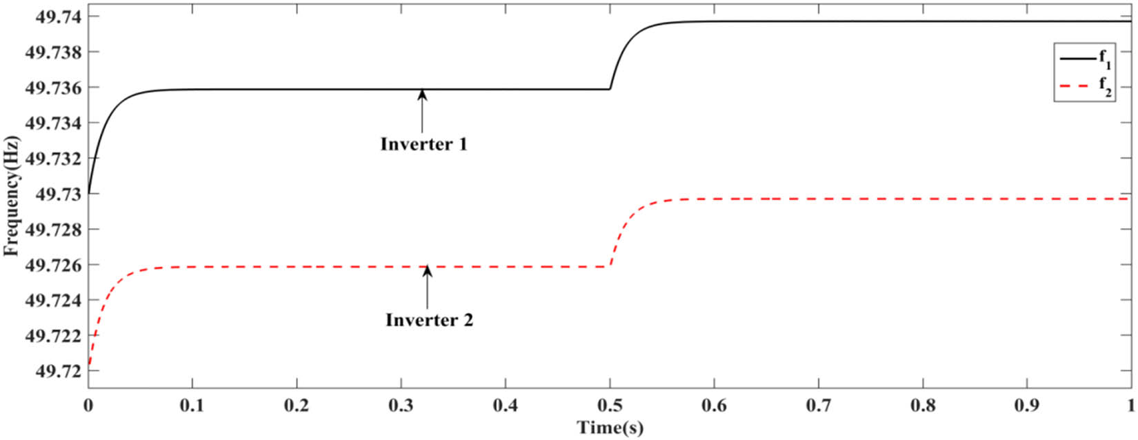
Parallel DG inverters output frequency using reverse droop control with step change in load.

Parallel DG inverters output voltage amplitude using reverse droop control with step change in load.
7 Conclusion
In low-voltage microgrids, the transmission line impedance is resistive, making the traditional reverse droop control unable to be used normally and the power coupling between active and reactive powers cannot achieve proportional load distribution. Based on the transmission characteristics, the difference between the microgrid and traditional grid droop control is analyzed, and the reverse droop control suitable for low-voltage microgrid is used as the basis for this study. Aiming at the coupling problem of active and reactive powers in low-voltage microgrid, the virtual resistance method is proposed to realize the decoupling control of active and reactive powers. A virtual resistor strategy is used to eliminate the effect of line impedance differences on power distribution. The influence of different line impedances on the power distribution of DG inverters is simulated and the effectiveness of the scheme is verified.
-
Conflict of interest: Authors state no conflict of interest.
References
[1] Zhao B. Key Technology of Microgrid Optimization and its Application. Beijing: Science Press; 2015.Suche in Google Scholar
[2] Yuan-Yuan X. The Research of Microgrid Comprehensive Control Strategy. Nanjing: Nanjing University of Science and Technology; 2014.Suche in Google Scholar
[3] Guo W, Mu L. Control principles of micro-source inverters used in microgrid. Prot Control Mod Power Syst. 2016;1:1–7.10.1186/s41601-016-0019-8Suche in Google Scholar
[4] Guerrero JM, Chandorkar M, Lee T, Loh PC. Advanced control architectures for intelligent microgrids-part-I: Decentralized and hierarchical control. IEEE Trans Ind Electron. 2013;6094:1254–62.10.1109/TIE.2012.2194969Suche in Google Scholar
[5] Guerrero JM, Vasquez JC, Matas J, De Vicuna LG. Hierarchical control of droop controlled ac and dc microgrids-A general approach towards standardization. IEEE Trans Ind Electron. 2011;58(1):158–72.10.1109/TIE.2010.2066534Suche in Google Scholar
[6] Guo F, Wen C. Distributed control subjected to constraints on control inputs: A case study on secondary control of droop controlled inverter based microgrids. Proc., 9th IEEE Conf. Ind. Electron. Appl. Hangzhou, China; 2014. p. 1119–24.10.1109/ICIEA.2014.6931333Suche in Google Scholar
[7] Guo Q. Research on parallel technology of distributed inverter system for flexible power sharing control. Phd thesis. Zhejiang University, China; 2016.Suche in Google Scholar
[8] Guo Q, Wu H, Lin L, Bai Z. Secondary voltage control for reactive power sharing in an islanded microgrid. J Power Electron. 2016;16(1):329–39.10.6113/JPE.2016.16.1.329Suche in Google Scholar
[9] Gupta A, Dolla S, Chatterjee K. Hybrid AC-DC microgrid: Systematic evaluation of control strategies. IEEE Trans Smart Grid. 2018;9(4):3830–43.10.1109/TSG.2017.2727344Suche in Google Scholar
[10] Han H, Liu Y, Sun Y, Su M, Guerrero JM. An improved droop control strategy for reactive power sharing in islanded microgrid. IEEE Trans Power Electron. 2015;30(6):3133–41.10.1109/TPEL.2014.2332181Suche in Google Scholar
[11] Han Y, Li H, Shen P, Coelho EAA, Guerrero JM. Review of active and reactive power sharing strategies in hierarchical controlled microgrids. IEEE Trans Power Electron. 2017;32(3):2427–51.10.1109/TPEL.2016.2569597Suche in Google Scholar
[12] Haoran L, Xuhong Y, Chengchen F. Control strategy research of output impedance analysis and improved droop control based on multiple inverters parallel. J power Syst Prot Control. 2015;43(20):29–35.Suche in Google Scholar
[13] Hasanzadeh A, Onar OC, Mokhtari H, Khaligh A. A Proportional resonant controller based wireless control strategy with a reduced number of sensors for parallel operated UPSs. IEEE Trans Power Delivery. 2010;25(1):468–78.10.1109/TPWRD.2009.2034911Suche in Google Scholar
[14] Hatziargyriou N. Overview of microgrid R&D in Europe. Symposium on Microgrids. Nagoya: 2007.Suche in Google Scholar
[15] Hatziargyriou N, Asano H, Iravani R, Marnay C. Microgrids: An overview of ongoing research, development and demonstration projects. IEEE Power Energy Mag. 2007;5(4):78–94.10.1109/MPAE.2007.376583Suche in Google Scholar
[16] He J, Li Y, Blaabjerg F. An enhanced islanding microgrid reactive power, imbalance power and harmonic power sharing scheme. IEEE Trans Power Electron. 2015;30(6):3389–401.10.1109/TPEL.2014.2332998Suche in Google Scholar
[17] He J, Li YW. An Enhanced Microgrid Load Demand Sharing Strategy. IEEE Trans Power Electron. 2012;27(9):3984–95.10.1109/TPEL.2012.2190099Suche in Google Scholar
[18] He Z, Wang X, Xing Y, Ma Y. Presynchronization control for parallel inverters based on power line communication. Proc., IEEE Power Electronics Specialists Conference; 2008. p. 3243–7.10.1109/PESC.2008.4592453Suche in Google Scholar
[19] Laaksonen H, Saari P, Komulainen R. Voltage and frequency control of inverter based weak LV network microgrid. 2005 International Conference on Future Power Systems. Amsterdam, Netherlands; November 18-18, 2005.10.1109/FPS.2005.204293Suche in Google Scholar
[20] Yao W, Chen M, Matas J, Guerrero JM, Qian ZM. Design and analysis of the droop control method for parallel inverters considering the impact of the complex impedance on the power sharing. IEEE Trans Ind Electron. 2011;58(2):576–88.10.1109/TIE.2010.2046001Suche in Google Scholar
[21] Yingwei K, Duhong W, Jingwei Z, Alhelou HH. Droop control strategy for multi-resistive inverters of low voltage microgrid based on adaptive virtual impedance. Sci Technol Eng. 2017;17(10):40–5.Suche in Google Scholar
[22] Mahmood H. Accurate reactive power sharing in an islanded microgrid using adaptive virtual impedances. IEEE Trans Power Electron. 2015;30(3):1605–17.10.1109/TPEL.2014.2314721Suche in Google Scholar
[23] Zhang H. Distributed adaptive virtual impedance control for accurate reactive power sharing based on consensus control in microgrids. IEEE Trans Smart Grid. 2017;8(4):1749–61.10.1109/TSG.2015.2506760Suche in Google Scholar
[24] Awal MA, Yu H, Tu H, Lukic SM. Hierarchical control for virtual oscillator based grid-connected and islanded microgrids. IEEE Trans Power Electron. 2020;35(1):988–1001.10.1109/TPEL.2019.2912152Suche in Google Scholar
[25] Chengshan W, Zhaoxia X, Shouxiang W. Multiple feedback loop control scheme for inverters of the micro-source in microgrids. Trans China Electrotech Soc. 2009;24(2):100–7.Suche in Google Scholar
[26] Pham MD, Lee HH. Effective coordinated virtual impedance control for accurate power sharing in islanded microgrid. IEEE Trans Ind Electron. 2021;68(3):2279–88.10.1109/TIE.2020.2972441Suche in Google Scholar
[27] Wai RJ, Zhang QQ, Wang Y. A novel voltage stabilization and power sharing control method based on virtual complex impedance for an off⁃grid microgrid. IEEE Trans Power Electron. 2019;34(2):1863–80.10.1109/TPEL.2018.2831673Suche in Google Scholar
[28] Yuan C, Cong S, Xu Y. Overview on grid-connected inverter virtual impedance technology for microgrid. Power Syst Prot Control. 2017;45(9):144–54.Suche in Google Scholar
© 2023 the author(s), published by De Gruyter
This work is licensed under the Creative Commons Attribution 4.0 International License.
Artikel in diesem Heft
- Regular Articles
- Design optimization of a 4-bar exoskeleton with natural trajectories using unique gait-based synthesis approach
- Technical review of supervised machine learning studies and potential implementation to identify herbal plant dataset
- Effect of ECAP die angle and route type on the experimental evolution, crystallographic texture, and mechanical properties of pure magnesium
- Design and characteristics of two-dimensional piezoelectric nanogenerators
- Hybrid and cognitive digital twins for the process industry
- Discharge predicted in compound channels using adaptive neuro-fuzzy inference system (ANFIS)
- Human factors in aviation: Fatigue management in ramp workers
- LLDPE matrix with LDPE and UV stabilizer additive to evaluate the interface adhesion impact on the thermal and mechanical degradation
- Dislocated time sequences – deep neural network for broken bearing diagnosis
- Estimation method of corrosion current density of RC elements
- A computational iterative design method for bend-twist deformation in composite ship propeller blades for thrusters
- Compressive forces influence on the vibrations of double beams
- Research on dynamical properties of a three-wheeled electric vehicle from the point of view of driving safety
- Risk management based on the best value approach and its application in conditions of the Czech Republic
- Effect of openings on simply supported reinforced concrete skew slabs using finite element method
- Experimental and simulation study on a rooftop vertical-axis wind turbine
- Rehabilitation of overload-damaged reinforced concrete columns using ultra-high-performance fiber-reinforced concrete
- Performance of a horizontal well in a bounded anisotropic reservoir: Part II: Performance analysis of well length and reservoir geometry
- Effect of chloride concentration on the corrosion resistance of pure Zn metal in a 0.0626 M H2SO4 solution
- Numerical and experimental analysis of the heat transfer process in a railway disc brake tested on a dynamometer stand
- Design parameters and mechanical efficiency of jet wind turbine under high wind speed conditions
- Architectural modeling of data warehouse and analytic business intelligence for Bedstead manufacturers
- Influence of nano chromium addition on the corrosion and erosion–corrosion behavior of cupronickel 70/30 alloy in seawater
- Evaluating hydraulic parameters in clays based on in situ tests
- Optimization of railway entry and exit transition curves
- Daily load curve prediction for Jordan based on statistical techniques
- Review Articles
- A review of rutting in asphalt concrete pavement
- Powered education based on Metaverse: Pre- and post-COVID comprehensive review
- A review of safety test methods for new car assessment program in Southeast Asian countries
- Communication
- StarCrete: A starch-based biocomposite for off-world construction
- Special Issue: Transport 2022 - Part I
- Analysis and assessment of the human factor as a cause of occurrence of selected railway accidents and incidents
- Testing the way of driving a vehicle in real road conditions
- Research of dynamic phenomena in a model engine stand
- Testing the relationship between the technical condition of motorcycle shock absorbers determined on the diagnostic line and their characteristics
- Retrospective analysis of the data concerning inspections of vehicles with adaptive devices
- Analysis of the operating parameters of electric, hybrid, and conventional vehicles on different types of roads
- Special Issue: 49th KKBN - Part II
- Influence of a thin dielectric layer on resonance frequencies of square SRR metasurface operating in THz band
- Influence of the presence of a nitrided layer on changes in the ultrasonic wave parameters
- Special Issue: ICRTEEC - 2021 - Part III
- Reverse droop control strategy with virtual resistance for low-voltage microgrid with multiple distributed generation sources
- Special Issue: AESMT-2 - Part II
- Waste ceramic as partial replacement for sand in integral waterproof concrete: The durability against sulfate attack of certain properties
- Assessment of Manning coefficient for Dujila Canal, Wasit/-Iraq
- Special Issue: AESMT-3 - Part I
- Modulation and performance of synchronous demodulation for speech signal detection and dialect intelligibility
- Seismic evaluation cylindrical concrete shells
- Investigating the role of different stabilizers of PVCs by using a torque rheometer
- Investigation of high-turbidity tap water problem in Najaf governorate/middle of Iraq
- Experimental and numerical evaluation of tire rubber powder effectiveness for reducing seepage rate in earth dams
- Enhancement of air conditioning system using direct evaporative cooling: Experimental and theoretical investigation
- Assessment for behavior of axially loaded reinforced concrete columns strengthened by different patterns of steel-framed jacket
- Novel graph for an appropriate cross section and length for cantilever RC beams
- Discharge coefficient and energy dissipation on stepped weir
- Numerical study of the fluid flow and heat transfer in a finned heat sink using Ansys Icepak
- Integration of numerical models to simulate 2D hydrodynamic/water quality model of contaminant concentration in Shatt Al-Arab River with WRDB calibration tools
- Study of the behavior of reactive powder concrete RC deep beams by strengthening shear using near-surface mounted CFRP bars
- The nonlinear analysis of reactive powder concrete effectiveness in shear for reinforced concrete deep beams
- Activated carbon from sugarcane as an efficient adsorbent for phenol from petroleum refinery wastewater: Equilibrium, kinetic, and thermodynamic study
- Structural behavior of concrete filled double-skin PVC tubular columns confined by plain PVC sockets
- Probabilistic derivation of droplet velocity using quadrature method of moments
- A study of characteristics of man-made lightweight aggregate and lightweight concrete made from expanded polystyrene (eps) and cement mortar
- Effect of waste materials on soil properties
- Experimental investigation of electrode wear assessment in the EDM process using image processing technique
- Punching shear of reinforced concrete slabs bonded with reactive powder after exposure to fire
- Deep learning model for intrusion detection system utilizing convolution neural network
- Improvement of CBR of gypsum subgrade soil by cement kiln dust and granulated blast-furnace slag
- Investigation of effect lengths and angles of the control devices below the hydraulic structure
- Finite element analysis for built-up steel beam with extended plate connected by bolts
- Finite element analysis and retrofit of the existing reinforced concrete columns in Iraqi schools by using CFRP as confining technique
- Performing laboratory study of the behavior of reactive powder concrete on the shear of RC deep beams by the drilling core test
- Special Issue: AESMT-4 - Part I
- Depletion zones of groundwater resources in the Southwest Desert of Iraq
- A case study of T-beams with hybrid section shear characteristics of reactive powder concrete
- Feasibility studies and their effects on the success or failure of investment projects. “Najaf governorate as a model”
- Optimizing and coordinating the location of raw material suitable for cement manufacturing in Wasit Governorate, Iraq
- Effect of the 40-PPI copper foam layer height on the solar cooker performance
- Identification and investigation of corrosion behavior of electroless composite coating on steel substrate
- Improvement in the California bearing ratio of subbase soil by recycled asphalt pavement and cement
- Some properties of thermal insulating cement mortar using Ponza aggregate
- Assessment of the impacts of land use/land cover change on water resources in the Diyala River, Iraq
- Effect of varied waste concrete ratios on the mechanical properties of polymer concrete
- Effect of adverse slope on performance of USBR II stilling basin
- Shear capacity of reinforced concrete beams with recycled steel fibers
- Extracting oil from oil shale using internal distillation (in situ retorting)
- Influence of recycling waste hardened mortar and ceramic rubbish on the properties of flowable fill material
- Rehabilitation of reinforced concrete deep beams by near-surface-mounted steel reinforcement
- Impact of waste materials (glass powder and silica fume) on features of high-strength concrete
- Studying pandemic effects and mitigation measures on management of construction projects: Najaf City as a case study
- Design and implementation of a frequency reconfigurable antenna using PIN switch for sub-6 GHz applications
- Average monthly recharge, surface runoff, and actual evapotranspiration estimation using WetSpass-M model in Low Folded Zone, Iraq
- Simple function to find base pressure under triangular and trapezoidal footing with two eccentric loads
- Assessment of ALINEA method performance at different loop detector locations using field data and micro-simulation modeling via AIMSUN
- Special Issue: AESMT-5 - Part I
- Experimental and theoretical investigation of the structural behavior of reinforced glulam wooden members by NSM steel bars and shear reinforcement CFRP sheet
- Improving the fatigue life of composite by using multiwall carbon nanotubes
- A comparative study to solve fractional initial value problems in discrete domain
- Assessing strength properties of stabilized soils using dynamic cone penetrometer test
- Investigating traffic characteristics for merging sections in Iraq
- Enhancement of flexural behavior of hybrid flat slab by using SIFCON
- The main impacts of a managed aquifer recharge using AHP-weighted overlay analysis based on GIS in the eastern Wasit province, Iraq