Assessment for behavior of axially loaded reinforced concrete columns strengthened by different patterns of steel-framed jacket
-
Muaid Adnan Shhatha
 and
Ahmed A. Alalikhan
and
Ahmed A. Alalikhan

Abstract
Rehabilitation, upgrading, or strengthening of structural members, especially columns, has become the target of many researchers because columns are the most important members in a building and the failure of columns causes direct collapse in the building. This study aims to get an assessment of the best pattern of steel-framed jacket used for strengthening axially loaded concrete columns by numerically studying the behavior of the column for different cases of the same amount of steel jacket. The jacket consists of four angles and/or battens, lacings, or battens with lacings. The nonlinear analysis program designated as ARCC-SSJ (Analysis of Reinforced Concrete Columns Strengthened by Steel Jacket) is used to compare different patterns with the same and different cross-sections of battens and single lacing, as well as battens and lacing with battens taken into account. It is found that lacing with battens is the best pattern for the same amount of steel jacket with different cross-sectional areas. It is observed that the load-carrying capacity of the column increased by approximately 1.8 and 1.15% over that of battens alone in the case of a lacing angle of
1 Introduction
Columns are the primary structural elements of a building. The need for periodic strengthening of columns is required to increase load-carrying capacity. This strengthening may be needed because of the use of additional live loads, deterioration of the load-bearing elements, structural problems, construction problems during building, or because the building is getting old or needs to be renovated to meet current standards and requirements [1]. The strengthening or rehabilitation of structural elements of a building requires studying performance of building and defining techniques to improve it, which is usually designer’s responsibility [2]. Many techniques are used for increasing the load-carrying capacity of columns, such as concrete jacketing, ferrocement jacketing, external prestressing, steel collars, fiber-reinforced polymer wrapping, and steel-framed jackets [3]. A steel-framed jacket is manufactured by four steel angles in the corners of a column with discrete steel straps welded horizontally, called battens, or welded in an inclined direction, called lacings, or using both of them, battens and lacings [4]. Figure 1 shows different patterns of steel-framed jackets. The steel-framed jacket method is considered economic, efficient, and easy to execute [3]. Moreover, it is a safe method through increasing the ductility due to confinement, so the member gives an indication before failure [5]. Besides that, this method improves the behavior of the structural member by increasing the shear resistance, axial, and flexure load capacities [6,7].
![Figure 1
Different patterns of steel-framed jackets [4]. (a) Battens, (b) single lacing, and (c) lacing and battens.](/document/doi/10.1515/eng-2022-0414/asset/graphic/j_eng-2022-0414_fig_001.jpg)
Different patterns of steel-framed jackets [4]. (a) Battens, (b) single lacing, and (c) lacing and battens.
Extensive studies are available that were performed in this area of strengthening reinforced concrete (RC) columns; most of them studied the column behavior experimentally [7–10]. The results of these studies were based on using one pattern of strengthening steel jacket. Khalifa and Al-Tersawy [7] established an experimental program to evaluate the improvement in stiffness, ductility, and load-carrying capacity of RC columns surrounded by steel jackets. To simulate the old local structures that needed to be strengthened in regional countries, the experimental test results had to have a low value of concrete strength. Jackets were created using steel plates that covered the entire column surface area; alternatively, they were made by connecting individual steel strips to steel angles at the corners of columns. The authors observed that the stiffening action of steel strips and angles enhances the confined concrete strength and therefore delays the sudden compression failure of the columns. It was also observed that increasing the strip thickness leads to increased confinement strength, so the strip in this case can achieve extra strain. Makki and Nimnim [8] investigated the behavior of RC columns with the same cross-section and height that were externally strengthened with a steel jacket when subjected to axial loads. The steel jacket was made up of four different-sized vertical steel angles attached to the column corners via horizontal battens, or it was made up of four vertical steel angles of constant size at the column corners, connected by varying sizes of steel plates at the top and bottom of the columns, in addition to horizontal battens. The authors found that the strengthening technique using steel jackets is applicable and can increase the ultimate load for all cases of strengthening by approximately 42–122% compared with the unstrengthened columns. Ezz-Eldeen [9] proved that the use of steel jacket technology with variable vertical angle sizes coupled with horizontal steel straps is valid to upgrade the load-carrying capacity of eccentrically loaded rectangular RC columns. The author found that increasing the covered area of the steel jacket by increasing the angle dimensions leads to an increase in the load-carrying capacity of the strengthened columns. Landovic and Besevic [10] presented experimental research on axially loaded RC columns with a square cross-section that are reinforced with a steel tube jacket and additional fill concrete. Failure modes of the specimens, as well as the load versus deformation and strain development relationships, were all recorded. The authors found that at all load levels, all three cross-sectional components (steel jacket, core column, and fill concrete) cooperated in the force-carrying processing. They also found that the steel tube and the infill concrete are engaged for load-carrying, even if the load is only applied to the core RC column. The load distribution on all three parts of the cross-section is achieved over the bond layer through the friction of adjacent materials. A new simple and efficient model that can control the behavior of short rectangular RC columns strengthened by a steel lattice-framed jacket was provided by Alwash and Al-Zahid [3]. They proposed a stress–strain diagram for confined concrete with internal reinforcement and an outside steel jacket. The authors concluded that the model can be used to study the interface nonlinearity between concrete and steel jacket. Depending on confinement properties, Campione et al. [11] assessed the dependability and effectiveness of various available analytical models for determining the load-bearing capacity of steel-jacketed RC columns under sustained loads. Within the analytical models, some of the strengthened column specimens are preloaded to a certain compressive stress and strain level before strengthening. According to the authors, the compressive behavior of preloaded specimens differs from that of non-preloaded specimens, with an increasing preloading level resulting in a lower load-bearing capacity. Kafel et al. [12] used the multi-criteria analysis method to select the appropriate solution method for strengthening columns constituting structural elements of historical buildings using strengthening jackets. Depending on the material, two types of strengthening jackets were proposed as reinforcement options: a mortar clamp reinforced with stirrups and a steel clamp made of steel angles and flat bars (battens). The results indicated that the multi-criteria analysis method was successfully applied to the reinforcement options for columns. However, assessing the priorities in the decision-making process related to the necessity of strengthening should take into account the archaeological, economic, social, and historical features of the buildings. In this study, an optimal pattern is determined by comparing and numerically evaluating the behavior of reinforced axially loaded concrete columns strengthened with three different patterns of steel-framed jackets. The jacket consists of four angles and/or battens, lacings, or battens with lacings. The results of this study are based on using the same amount of steel for battens, lacings, and battens with lacing with different cross-section areas and comparing in between. Also, an empirical model for the spring stiffness of the concrete-steel jacket interface is considered in the analysis due to a lack of information in this field.
2 Method of analysis
This section provides a synopsis of the approach that was used to conduct an analytical analysis of RC columns strengthened with steel lattice jackets. The analysis method is based on the exact stiffness matrix of an axially loaded, RC column strengthened with a steel jacket. Three different patterns of strengthening jackets are used in the analysis, in which the jacket is made by four steel angles in the corners of a column with horizontally welded discrete steel straps (battens), welded in an inclined direction (lacings), or using both of them, battens and lacings. This method is suggested to make a major comparison between different patterns of strengthening jackets by converting the pattern of jacket from single lacing or battens with single lacing to equivalent battens using the same amount of steel with different cross-sectional areas of lacings and battens. The numerical analysis of the strengthened columns by steel jacket, according to the present suggested method, is achieved using a nonlinear finite element visual basic language program designated as ARCC-SSJ [3] (Analysis of Reinforced Concrete Columns Strengthened by Steel Jacket). The program is dependent on the exact solution of the finite elements for columns supplemented with a steel lattice frame jacket. The displacement field is exactly determined in accordance with the concept of minimum strain energy. The analysis of the strengthened columns by steel jacket, according to the present suggested method, assumed that the bottom of the columns is a fixed end, and there are three degrees of freedom at the top, namely longitudinal displacement in the concrete, longitudinal displacement in the steel jacket, and longitudinal displacement in the reinforcement. The confinement of internal reinforcement and the external steel-framed jacket have been taken into consideration. The nonlinearity of materials and interface between the concrete column face and the steel-framed jacket have been included. The main equations that have been used for analysis are presented as follows:
The displacement field equation that has been adopted to drive the stiffness matrix [13]:
(1)where
As stated by Campione [6], the equation for confined pressures induced by stirrups and internal longitudinal bars is as follows:
(2)where
The equation of confining pressure (CP) due to the steel jacket is as follows [6]:
(3)where
(4)Empirical model for the spring stiffness of the concrete-steel jacket interface.
Chemical adhesion, friction, and mechanical interlock between reinforcement and concrete all contribute to the bond strength between rebar and surrounding concrete. The steel jacket and concrete interface spring stiffness do not include chemical adhesion or mechanical interlock. Furthermore, the parameters of any formula used to evaluate such stiffness for the axially loaded columns do not account the transverse expansion due to Poisson’s ratio. Hence, the stiffness was determined practically. The empirical equation of the interface spring stiffness between concrete and steel jacket becomes [3]
(5)where
A stress–strain curve for confined concrete that has been proposed is shown in Figure 3.
At a certain level of strain, the corresponding stress value will be greater in confined concrete; the ultimate strength of confined concrete can be found from equation (6) according to the provisions of Euro code 8 [14]:
(6)The ultimate strain of confined concrete can be evaluated from equation (7), adopted by Mander et al. [15].
(7)where

Dimension details of steel angle.
![Figure 3
Stress–strain curve for confined concrete [3].](/document/doi/10.1515/eng-2022-0414/asset/graphic/j_eng-2022-0414_fig_003.jpg)
Stress–strain curve for confined concrete [3].
3 Comparison between experimental and analytical results
The efficiency and validity of the method of analysis used in this study are validated via comparison with other experimental results. Two verification case studies are performed in this section to compare the results of the analytical analysis of this study using the ARCC-SSJ program to the experimentally tested data used by Campoine [6,16] and Adam et al. [17] for axially loaded RC columns strengthened with steel frame jackets. In those cases, the need for strengthening is due to problems with strength caused by substandard concrete used in construction (real strength below design) or to replicate the situation of old local structures that needed to be strengthened [7,17]. In the first case, an RC column with a
The strengthening jacket consisted of angles and battens welded together around the column. Four angles are used at the corners of the column. The side length of each one is 30 mm, and the thickness is 3 mm, while the yield stress is 239 MPa. The battens were 30 mm in width and 3 mm in thickness. The spacing between battens equals 200 mm from center to center. The yield stress is 239 MPa. Figure 4 shows the main form of input data for the program to analyze the strengthened column. Figure 5 shows the relationship between applied load and concrete longitudinal strain. A good agreement is found between Campione’s [16] experimental work and this study.
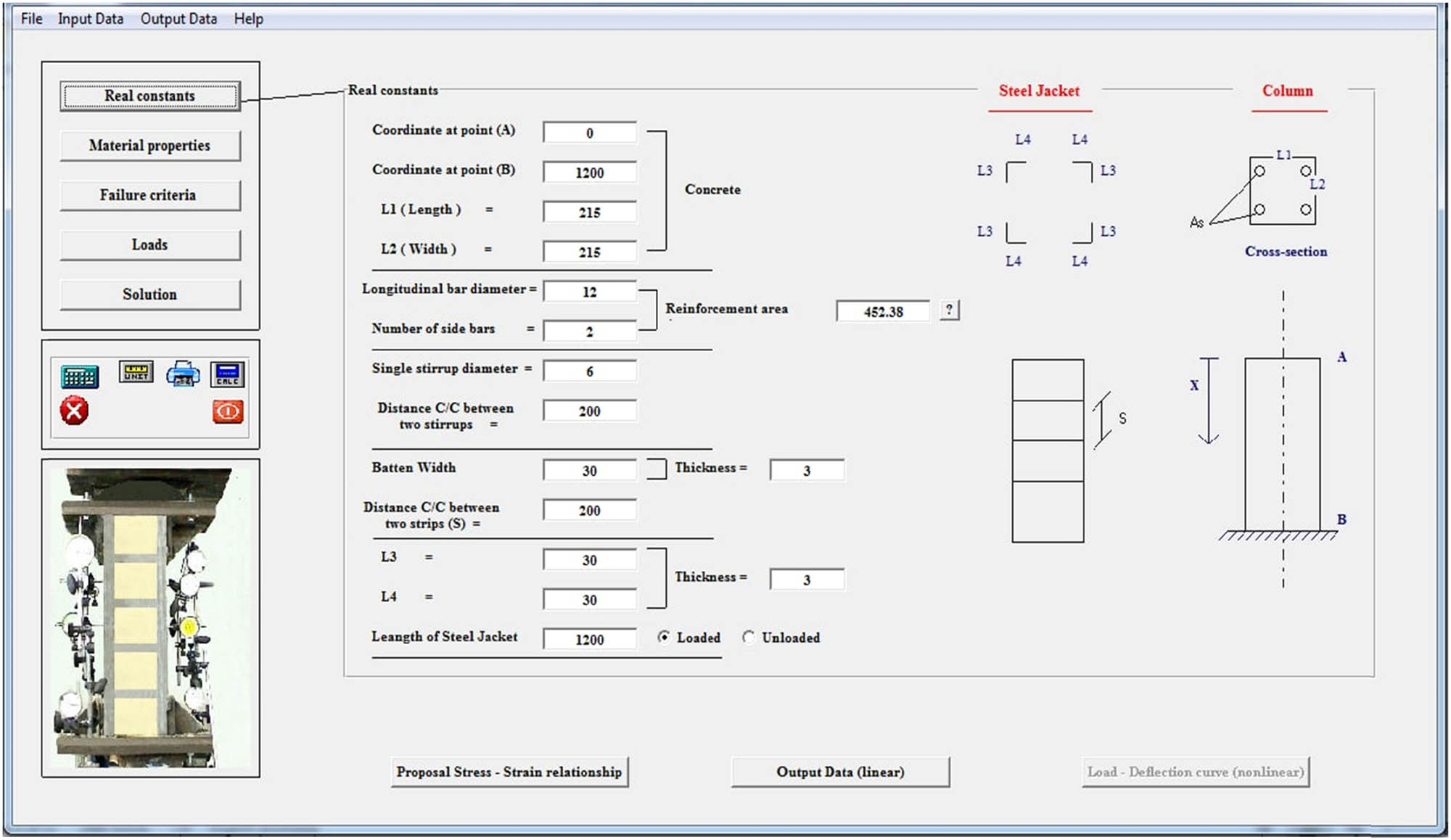
ARCC-SSJ program.

Load–strain curve of column for this study and experimental work.
In the second case, a comparison of the experimental results of Adam et al. [17] and this study with and without including the effect of interface spring stiffness between concrete and steel is presented. In the analysis, an RC column with a
The analysis revealed that there is a normal pressure from the concrete to the steel angle due to the expansion of the concrete due to the effect of Poisson’s ratio; this pressure will increase the friction between the concrete and the steel angle. On the other hand, the interface element between the concrete and the steel jacket takes into consideration this effect, and equation (5) presents a one-dimensional interface that includes the effect of normal pressure. So, the results of this study (load versus concrete strain), including the effect of an interface spring, have been very close to Adam’s [17] experimental work, while the stiffness matrix without an interface spring shows inappropriate results as shown in Figure 6.
![Figure 6
Comparison of experimental results by Adam et al. [17] with this study (with and without the effect of interface spring stiffness).](/document/doi/10.1515/eng-2022-0414/asset/graphic/j_eng-2022-0414_fig_006.jpg)
Comparison of experimental results by Adam et al. [17] with this study (with and without the effect of interface spring stiffness).
Both cases of verification compare the results of the adopted analytical model with experimental work to get good confidence in the results, but the difference between the two cases (Campoine et al. [16] and Adam et al. [17]) was the behavior of columns at 1,000 kN. The concrete strain in the Campoine specimen was extremely higher than the concrete strain for the Adam et al. specimen, so the adopted analytical model has good results for both types of failure, brittle or ductile.
4 Analysis results and discussions
This section includes the results of the comparison between battens and single lacing and the comparison between battens and battens with lacing. The dimensions and properties of the concrete column and steel jacket mentioned in the first verification case are adopted in the analysis. The load capacity for eight case studies is found through the results of the ARCC-SSJ program and compared with each other to obtain the best pattern for strengthening. The results have been discussed to find the best pattern of steel frame jacket using the same amount of steel with the same or different cross-section area of lacing and battens. In the research case studies, the angle of the lacing with respect to the longitudinal axis of the column was taken as

Details of battens and lacings for different case patterns of steel jacket. (a) Battens, (b) single lacing, and (c) lacing and battens.
4.1 Comparison between battens and single lacings
This comparison is between battens (Figure 7(a)) and single lacings (Figure 7(b)). The comparison includes two cases. The first case included the same amount of steel with different cross-sectional areas of battens and lacings, while the second case uses the same cross-sectional areas of battens and lacings.
4.1.1 Same amount of steel with different cross-sectional areas of lacings and battens
The ARCC-SSJ program has been used to get the load-carrying capacity. To convert the lacing form into the batten form, an equivalent calculation is performed. The following steps show the procedure for replacing the lacing with equivalent battens:
Lacing with angle
Length of lacing = 246.22 mm,
Equivalent spacing = 240.
Length of column = 1,200 mm, so the number of lacing equal to 10 with the same density, depend on the volume of lacing to find the same amount of steel jacket. Therefore, the equivalent area of angle will be
Equivalent area of angle = 180 + 43.86 = 223.86 mm
Equivalent thickness of angle = 3.73 mm.
Battens’ equivalent cross-sectional area =
Battens’ equivalent cross-sectional area = 157.17 mm
Therefore, the required equivalent details in battens form are as follows: Length of batten = 215 mm.
Number of battens = 9.
Width of batten =
Spacing of battens = 120 mm.
Lacing with angle
Length of lacing = 223.21 mm.
where equivalent spacing = 120.
Length of column = 1,200 mm. So, the number of lacings is equal to 20.
With the same density, based on volume of lacing the same amount of steel is found. Therefore, equivalent area of angle will be:
where equivalent area of angle = 180 + 24.19 = 204.19 mm
Equivalent thickness of angle = 3.4 mm.
Battens’ equivalent cross-sectional area =
Battens’ equivalent cross-sectional area = 2
So, the required equivalent details in battens form are as follows:
Length of batten = 215 mm.
Number of battens = 19.
Width of batten =
Spacing of battens = 60 mm. The details and maximum load-carrying capacity are summarized in Table 1.
Comparison of battens and single lacing (same amount of steel jacket, different cross-section area)
| Details | First case | Second case | ||
|---|---|---|---|---|
| Battens | Single lacing
|
Battens | Single lacing
|
|
| Spacing of battens (mm) | 120 | 240 | 60 | 120 |
| Width of battens (mm) | 38.17 | 52.39 | 32.78 | 57.79 |
| Angle thickness (mm) | 3 | 3.73 | 3 | 3.34 |
| Maximum load capacity (kN) | 1,044 | 936 | 1,263 | 1,123 |
4.1.2 Same amount of steel with the same cross-section dimensions of lacings and battens
As shown in the following steps, an equivalent calculation is performed to convert the lacing form into battens with the same cross-section area:
Volume of lacing (60.832) = (length
Volume of lacing = 246.22
For the same volume of steel jacket, (221,598 = 30
No. of battens = 11.45, use (11), Spacing of battens = 100 mm.
Volume of lacing (74.407) = (length
Volume of lacing = 223.21
For the same volume of steel jacket (401,778 = 30
No. of battens = 20.76; using (20), spacing of battens = 57 mm. Table 2 summarizes the details and maximum load-carrying capability.
Comparison of battens and single lacing (same amount of steel jacket, same cross-sectional area)
| Details | First case | Second case | ||
|---|---|---|---|---|
| Battens | Single lacing 60.832
|
Battens | Single lacing 74.407
|
|
| Spacing of battens (mm) | 100 | 240 | 57 | 120 |
| Width of battens (mm) | 30 | 52.39 | 30 | 57.79 |
| Angle thickness (mm) | 3 | 3.73 | 3 | 3.34 |
| Maximum load capacity (kN) | 1,067 | 936 | 1,261 | 1,123 |
4.2 Comparison between only battens and lacings with battens
This comparison is between battens shown in Figure 7(a) and lacing with battens shown in Figure 7(c). The comparison includes two cases: one with the same amount of steel but a different cross-section area of lacings and battens, and the other with the same cross-section of lacings and battens.
4.2.1 Same amount of steel with different cross-sectional areas of lacings and battens
The equivalent calculations and maximum load capacity are summarized in Table 3.
Comparison between battens and lacings with battens (same amount of steel jacket, different cross-sectional area)
| Details | First case | Second case | ||
|---|---|---|---|---|
| Battens | Battens with lacing 60.832
|
Battens | Battens with lacing 74.407
|
|
| Spacing of battens (mm) | 120 | 120 | 60 | 60 |
| Width of battens (mm) | 68.17 | 56.193 | 62.78 | 58.893 |
| Angle thickness (mm) | 3 | 3.73 | 3 | 3.4 |
| Maximum load capacity (kN) | 1,120 | 1,141 | 1,462 | 1,479 |
4.2.2 Same amount of steel with the same cross-sectional area of lacings and battens
The equivalent calculations and maximum load capacity are summarized in Table 4.
Comparison between battens and lacings with battens (same amount of steel jacket, same cross-sectional area)
| Details | First case | Second case | ||
|---|---|---|---|---|
| Battens | Battens with lacing 60.832
|
Battens | Battens with lacing 74.407
|
|
| Spacing of battens (mm) | 57 | 120 | 30 | 60 |
| Width of battens (mm) | 30 | 56.193 | 30 | 58.893 |
| Angle thickness (mm) | 3 | 3.73 | 3 | 3.4 |
| Maximum load capacity (kN) | 1,261 | 1,141 | 1,578 | 1,479 |
4.3 Discussion of the results
The primary structural principle is that axial strain in concrete causes lateral strain due to Poisson’s ratio, which is caused by the fact that confined concrete resists more axial load, and the lateral strain increases the value of the interface spring stiffness between concrete and steel jackets. So, the results of battens without lacing are considered good patterns. According to the results shown in Tables 1–4, decreasing the spacing between battens by about 1% causes an increase in maximum load-carrying capacity of about 0.5%. As a result, when battens and lacing are used with varying cross-sections, the maximum load-carrying capacity is increased by about 1.8 and 1.15%, respectively, over battens without lacing in the first and second cases (lacing:

Different percentages of maximum load-carrying capacity for different patterns.
Even though using battens alone produces good results in terms of the maximum load-carrying capacity, using battens and lacings is still necessary to upgrade the results of load-carrying capacity and get improvements in the behavior of the strengthened columns because the lacing has double action in terms of a steel jacket, axial resistance, and confining.
5 Conclusion
For the same amount of steel jacket with the same or different cross-sectional area of lacing and battens, the lacing pattern is considered the worst compared with battens alone.
Battens without lacing are considered a good pattern for the same amount of steel in a jacket with the same cross-sectional area of lacings and battens. By reducing the spacing between battens by about 1%, the maximum load-carrying capacity increases by about 0.5%.
The pattern of lacing with battens improves the behavior of the column and increases the maximum load-carrying capacity by about 1.8 and 1.15% more than that of battens without lacing for lacing
-
Conflict of interest: The authors state no conflict of interest.
-
Data availability statement: Most datasets generated and analyzed in this study are comprised in this submitted manuscript. The other datasets are available upon a reasonable request from the corresponding author with the attached information.
References
[1] Belal MF, Mohamed HM, Morad SA. Behavior of reinforced concrete columns strengthened by steel jacket. HBRC J. 2015;11(2):201–12. 10.1016/j.hbrcj.2014.05.002Search in Google Scholar
[2] Abreu A, Calado J, Requeijo J. Buildings lean maintenance implementation model. Open Eng. 2016;6(1):397–406. 10.1515/eng-2016-0055Search in Google Scholar
[3] Alwasha NA, Al-Zahid AA. Behavior of reinforced concrete short rectangular columns strengthened by steel lattice framed jacket. In: COMPLAS XIII: Proceedings of the XIII International Conference on Computational Plasticity: Fundamentals and Applications. CIMNE; 2015. p. 471–82. Search in Google Scholar
[4] Salmon CG, Johnson JE. Steel structures: design and behavior. New York: HarperCollins College Publishers; 1995. Search in Google Scholar
[5] Minafò G, Siciliano AF, Fossetti M. Modelling load-transmission mechanisms in axially loaded RC columns retrofitted with steel jackets. In: Proceedings of the 1st International Conference on Numerical Modelling in Engineering: Volume 1 Numerical Modelling in Civil Engineering, NME 2018, 28–29 August 2018, Ghent University, Belgium: Springer; 2019. p. 90–111. 10.1007/978-981-13-2405-5_8Search in Google Scholar
[6] Campione G. Strength and ductility of RC columns strengthened with steel angles and battens. Construction Building Materials. 2012;35:800–7. 10.1016/j.conbuildmat.2012.04.090Search in Google Scholar
[7] Khalifa ES, Al-Tersawy SH. Experimental and analytical behavior of strengthened reinforced concrete columns with steel angles and strips. Int J Adv Struct Eng (IJASE). 2014;6:1–14. 10.1007/s40091-014-0061-6Search in Google Scholar
[8] Makki RF, Nimnim ST. Rehabilitation of structural columns by using steel angles. Int J Scientif Eng Res. 2015;1(6):981–7. Search in Google Scholar
[9] Ezz-Eldeen H. Steel jacketing technique used in strengthening reinforced concrete rectangular columns under eccentricity for practical design applications. Int J Eng Trends Technol (IJETT). 2016;35(5):195–204. 10.14445/22315381/IJETT-V35P243Search in Google Scholar
[10] Landović A, Bešević M. Experimental research on reinforced concrete columns strengthened with steel jacket and concrete infill. Appl Sci. 2021;11(9):4043. 10.3390/app11094043Search in Google Scholar
[11] Campione G, Cannella F, Cavaleri L, Ferrotto M, Papia M. Assessment of the load carrying capacity of reinforced concrete columns strengthened by steel cages Specificità nella valutazione della capacità portante di colonne in calcestruzzo armato rinforzate con incamiciatura in acciaio. In: Proceedings of Italian Concrete Days 2018. di Prisco, Marco, Menegotto, Marco; 2018. Search in Google Scholar
[12] Kafel K, Leśniak A, Zima K. Multicriteria comparative analysis of pillars strengthening of the historic building. Open Eng. 2019;9(1):18–25. 10.1515/eng-2019-0003Search in Google Scholar
[13] Alwash A. One dimensional composite axial finite element including bond slip. J Babylon Univ. 2006;12:904–16. Search in Google Scholar
[14] Standard B. Eurocode 8: Design of structures for earthquake resistance strengthening and repair of buildings. Part. 2005;3:1998–3. Search in Google Scholar
[15] Mander JB, Priestley MJ, Park R. Theoretical stress–strain model for confined concrete. J Struct Eng. 1988;114(8):1804–26. 10.1061/(ASCE)0733-9445(1988)114:8(1804)Search in Google Scholar
[16] Campione G, Minafo G, Papia M. Flexural behavior of RC columns strengthened with steel angles and strips. In: Atti del XIV Convegno ANIDIS (CD-ROM). Realizzazione editoriale Digilabs; 2011. 10.1016/j.engstruct.2012.03.006Search in Google Scholar
[17] Adam JM, Ivorra S, Pallarés F, Giménez E, Calderón P. Axially loaded RC columns strengthened by steel cages. Proc Institut Civil Eng Struct Buildings. 2009;162(3):199–208. 10.1680/stbu.2009.162.3.199Search in Google Scholar
© 2023 the author(s), published by De Gruyter
This work is licensed under the Creative Commons Attribution 4.0 International License.
Articles in the same Issue
- Regular Articles
- Design optimization of a 4-bar exoskeleton with natural trajectories using unique gait-based synthesis approach
- Technical review of supervised machine learning studies and potential implementation to identify herbal plant dataset
- Effect of ECAP die angle and route type on the experimental evolution, crystallographic texture, and mechanical properties of pure magnesium
- Design and characteristics of two-dimensional piezoelectric nanogenerators
- Hybrid and cognitive digital twins for the process industry
- Discharge predicted in compound channels using adaptive neuro-fuzzy inference system (ANFIS)
- Human factors in aviation: Fatigue management in ramp workers
- LLDPE matrix with LDPE and UV stabilizer additive to evaluate the interface adhesion impact on the thermal and mechanical degradation
- Dislocated time sequences – deep neural network for broken bearing diagnosis
- Estimation method of corrosion current density of RC elements
- A computational iterative design method for bend-twist deformation in composite ship propeller blades for thrusters
- Compressive forces influence on the vibrations of double beams
- Research on dynamical properties of a three-wheeled electric vehicle from the point of view of driving safety
- Risk management based on the best value approach and its application in conditions of the Czech Republic
- Effect of openings on simply supported reinforced concrete skew slabs using finite element method
- Experimental and simulation study on a rooftop vertical-axis wind turbine
- Rehabilitation of overload-damaged reinforced concrete columns using ultra-high-performance fiber-reinforced concrete
- Performance of a horizontal well in a bounded anisotropic reservoir: Part II: Performance analysis of well length and reservoir geometry
- Effect of chloride concentration on the corrosion resistance of pure Zn metal in a 0.0626 M H2SO4 solution
- Numerical and experimental analysis of the heat transfer process in a railway disc brake tested on a dynamometer stand
- Design parameters and mechanical efficiency of jet wind turbine under high wind speed conditions
- Architectural modeling of data warehouse and analytic business intelligence for Bedstead manufacturers
- Influence of nano chromium addition on the corrosion and erosion–corrosion behavior of cupronickel 70/30 alloy in seawater
- Evaluating hydraulic parameters in clays based on in situ tests
- Optimization of railway entry and exit transition curves
- Daily load curve prediction for Jordan based on statistical techniques
- Review Articles
- A review of rutting in asphalt concrete pavement
- Powered education based on Metaverse: Pre- and post-COVID comprehensive review
- A review of safety test methods for new car assessment program in Southeast Asian countries
- Communication
- StarCrete: A starch-based biocomposite for off-world construction
- Special Issue: Transport 2022 - Part I
- Analysis and assessment of the human factor as a cause of occurrence of selected railway accidents and incidents
- Testing the way of driving a vehicle in real road conditions
- Research of dynamic phenomena in a model engine stand
- Testing the relationship between the technical condition of motorcycle shock absorbers determined on the diagnostic line and their characteristics
- Retrospective analysis of the data concerning inspections of vehicles with adaptive devices
- Analysis of the operating parameters of electric, hybrid, and conventional vehicles on different types of roads
- Special Issue: 49th KKBN - Part II
- Influence of a thin dielectric layer on resonance frequencies of square SRR metasurface operating in THz band
- Influence of the presence of a nitrided layer on changes in the ultrasonic wave parameters
- Special Issue: ICRTEEC - 2021 - Part III
- Reverse droop control strategy with virtual resistance for low-voltage microgrid with multiple distributed generation sources
- Special Issue: AESMT-2 - Part II
- Waste ceramic as partial replacement for sand in integral waterproof concrete: The durability against sulfate attack of certain properties
- Assessment of Manning coefficient for Dujila Canal, Wasit/-Iraq
- Special Issue: AESMT-3 - Part I
- Modulation and performance of synchronous demodulation for speech signal detection and dialect intelligibility
- Seismic evaluation cylindrical concrete shells
- Investigating the role of different stabilizers of PVCs by using a torque rheometer
- Investigation of high-turbidity tap water problem in Najaf governorate/middle of Iraq
- Experimental and numerical evaluation of tire rubber powder effectiveness for reducing seepage rate in earth dams
- Enhancement of air conditioning system using direct evaporative cooling: Experimental and theoretical investigation
- Assessment for behavior of axially loaded reinforced concrete columns strengthened by different patterns of steel-framed jacket
- Novel graph for an appropriate cross section and length for cantilever RC beams
- Discharge coefficient and energy dissipation on stepped weir
- Numerical study of the fluid flow and heat transfer in a finned heat sink using Ansys Icepak
- Integration of numerical models to simulate 2D hydrodynamic/water quality model of contaminant concentration in Shatt Al-Arab River with WRDB calibration tools
- Study of the behavior of reactive powder concrete RC deep beams by strengthening shear using near-surface mounted CFRP bars
- The nonlinear analysis of reactive powder concrete effectiveness in shear for reinforced concrete deep beams
- Activated carbon from sugarcane as an efficient adsorbent for phenol from petroleum refinery wastewater: Equilibrium, kinetic, and thermodynamic study
- Structural behavior of concrete filled double-skin PVC tubular columns confined by plain PVC sockets
- Probabilistic derivation of droplet velocity using quadrature method of moments
- A study of characteristics of man-made lightweight aggregate and lightweight concrete made from expanded polystyrene (eps) and cement mortar
- Effect of waste materials on soil properties
- Experimental investigation of electrode wear assessment in the EDM process using image processing technique
- Punching shear of reinforced concrete slabs bonded with reactive powder after exposure to fire
- Deep learning model for intrusion detection system utilizing convolution neural network
- Improvement of CBR of gypsum subgrade soil by cement kiln dust and granulated blast-furnace slag
- Investigation of effect lengths and angles of the control devices below the hydraulic structure
- Finite element analysis for built-up steel beam with extended plate connected by bolts
- Finite element analysis and retrofit of the existing reinforced concrete columns in Iraqi schools by using CFRP as confining technique
- Performing laboratory study of the behavior of reactive powder concrete on the shear of RC deep beams by the drilling core test
- Special Issue: AESMT-4 - Part I
- Depletion zones of groundwater resources in the Southwest Desert of Iraq
- A case study of T-beams with hybrid section shear characteristics of reactive powder concrete
- Feasibility studies and their effects on the success or failure of investment projects. “Najaf governorate as a model”
- Optimizing and coordinating the location of raw material suitable for cement manufacturing in Wasit Governorate, Iraq
- Effect of the 40-PPI copper foam layer height on the solar cooker performance
- Identification and investigation of corrosion behavior of electroless composite coating on steel substrate
- Improvement in the California bearing ratio of subbase soil by recycled asphalt pavement and cement
- Some properties of thermal insulating cement mortar using Ponza aggregate
- Assessment of the impacts of land use/land cover change on water resources in the Diyala River, Iraq
- Effect of varied waste concrete ratios on the mechanical properties of polymer concrete
- Effect of adverse slope on performance of USBR II stilling basin
- Shear capacity of reinforced concrete beams with recycled steel fibers
- Extracting oil from oil shale using internal distillation (in situ retorting)
- Influence of recycling waste hardened mortar and ceramic rubbish on the properties of flowable fill material
- Rehabilitation of reinforced concrete deep beams by near-surface-mounted steel reinforcement
- Impact of waste materials (glass powder and silica fume) on features of high-strength concrete
- Studying pandemic effects and mitigation measures on management of construction projects: Najaf City as a case study
- Design and implementation of a frequency reconfigurable antenna using PIN switch for sub-6 GHz applications
- Average monthly recharge, surface runoff, and actual evapotranspiration estimation using WetSpass-M model in Low Folded Zone, Iraq
- Simple function to find base pressure under triangular and trapezoidal footing with two eccentric loads
- Assessment of ALINEA method performance at different loop detector locations using field data and micro-simulation modeling via AIMSUN
- Special Issue: AESMT-5 - Part I
- Experimental and theoretical investigation of the structural behavior of reinforced glulam wooden members by NSM steel bars and shear reinforcement CFRP sheet
- Improving the fatigue life of composite by using multiwall carbon nanotubes
- A comparative study to solve fractional initial value problems in discrete domain
- Assessing strength properties of stabilized soils using dynamic cone penetrometer test
- Investigating traffic characteristics for merging sections in Iraq
- Enhancement of flexural behavior of hybrid flat slab by using SIFCON
- The main impacts of a managed aquifer recharge using AHP-weighted overlay analysis based on GIS in the eastern Wasit province, Iraq