Experimental study on basic mechanical properties of recycled steel fiber reinforced concrete
-
Yongtao Gao
 ,
Bin Wang
,
Changjiang Liu
,
David Hui
,
Bin Wang
,
Changjiang Liu
,
David Hui

Abstract
Recycled steel fiber (RSF)-reinforced concrete is not only an innovative research trend in the field of civil engineering materials, but also a new type of civil engineering composites under the trend of low-carbon development. This article deals with the experimental study of applying waste steel fibers to form recycled steel fiber concrete (RSFC). The main materials in this study are RSF, coarse and fine aggregate, fly ash, silica fume, and water reducer agent formed by machining surplus materials as the main materials. Three types of concrete were prepared. They were normal concrete, primary steel fiber concrete (PSFC), and RSFC with six different volume contents. The slump and air content of the three types of concrete are compared and analyzed. Then, the effects of the volume content of RSF on the cube compressive strength, splitting tensile strength, flexural strength, and axial compressive strength of RSFC are studied. Finally, the toughness of RSFC is discussed. The test results show that with the increase in the volume content of RSF, the slump of RSFC is significantly reduced, the compressive strength, tensile strength, and flexural strength are enhanced, the increase in tensile strength and flexural strength is significantly higher than the cube compressive strength, and the RSF has an obvious inhibitory effect on the development of concrete cracks which can obviously enhance the ductility and toughness of the concrete.
1 Introduction
With the rapid development of China’s economy, the urban population is also growing rapidly, and housing and infrastructure should continue to meet the needs of economic development and population growth [1,2]. Concrete is one of the main materials in civil engineering, and steel fiber (SF)-reinforced concrete is one of the main composite materials formed by concrete to reduce cracking [3,4]. The world consumes nearly 100 million tons of steel every year to manufacture various specifications of SFs, while the world forms as much as 200 million tons of surplus materials through mechanical processing every year. If these wastes are made into regenerated SFs, they will not only reduce the waste of resources, but also reduce pollution [5,6,7,8].
The surplus materials formed by machining are used as SF, that is, recycled steel fiber (RSF). Adding RSF instead of primary steel fiber (PSF) into concrete to form RSFC is another innovative way to form composite concrete materials [9]. The shape of RSF is different from that of the PSF. It is generally spiral, which can form a spatial skeleton in the concrete and effectively arrest the cracks in the concrete, so as to improve the crack resistance and ductility of concrete [10,11,12,13,14,15]. In addition, RSF does not need to be re produced, which reduces the emission of greenhouse gases and the stacking of solid waste, and finds a new method to protect the soil from pollution. Therefore, it is an ideal choice to partially replace the original SF with RSF. Using RSFC is a new method of civil engineering material innovation [16,17,18,19,20].
Although the shape of RSF is generally spiral, there are differences in spiral curvature, fiber length, length diameter ratio, and formation process. Even some RSFs contain grease on the surface during the formation process. These factors will affect the mechanical properties of RSFC, which may have favorable or unfavorable effects. At present, there is no mature and reliable test conclusion [21,22,23,24,25]. At present, the research on RSF is mainly to use the waste SF in the tire [26,27,28,29,30]. During the cutting process of steel by mechanical tools, shaving steel wastes will be produced. These steel wastes will form spiral RSFs after length shear. When the spiral RSFs are added to the concrete mixture, they will form a three-dimensional bonding skeleton structure with cement mortar. However, there are few research literature on this kind of SFC.
The research focus of RSF-reinforced concrete mainly focuses on the stripping of steel wires from waste tires, while the experimental work of steel-fiber-reinforced concrete formed by machining has not started on a large scale. The basic mechanical properties of RSF-reinforced concrete formed by machining are studied by referring to the existing similar documents of RSFC [31,32], through the tests of one group of ordinary concrete, one group of primary steel fiber concrete (PSFC), and six groups of RSFC with different volume contents, and by analyzing the effects of RSF with different volume contents on the slump, air content, cube compressive strength, splitting tensile strength, flexural strength, and axial compressive strength. The spiral structure of RSF is explored to analyze whether it can really form a three-dimensional skeleton structure, so as to verify whether the previous conjecture is reasonable. In addition, the toughness of RSF to concrete is analyzed.
2 Test materials and methods
2.1 Test materials and mix proportion
The RSF comes from Chengdu Xingguang machinery factory. It has a spiral curl shape (Figure 1a), with length of 3–6 cm, thickness of 0.25–0.35 mm, width of 1.5–3.5 mm, length-to-diameter ratio of about 20–25, average tensile strength of 381.3 MPa and elastic modulus of 1.997 × 10⁵ MPa. In order to ensure that the length of SF is consistent and uniform, the raw materials of RSF shall be sorted and cut before use to ensure that the length of RSF is generally kept at 3–6 cm. The PSF is of milling type (Figure 1b), with a length of 60 mm, the length-to-diameter ratio of 65, the tensile strength of 400 MPa and the elastic modulus is 2.01 × 10⁵ MPa. The cement is P.O 42.5 ordinary Portland cement (Figure 1c). The coarse aggregate is a mixture of crushed stone and bean stone, with a mass ratio of 70 and 30%, respectively (Figure 1d and e). The fine aggregate is a mixture of natural sand and quartz sand, with a mass ratio of 70 and 30%, respectively (Figure 1f and g). Fly ash is class F product produced by Shanxi Houma iron and Steel Co., Ltd. (Figure 1h), silica fume is silica fume for concrete produced by Gansu Sanyuan Silicon Material Co., Ltd. (Figure 1i), water reducer is polycarboxylate superplasticizer (Figure 1j), and mixing water is common tap water. Table 1 shows the mix proportion of different types of concrete.
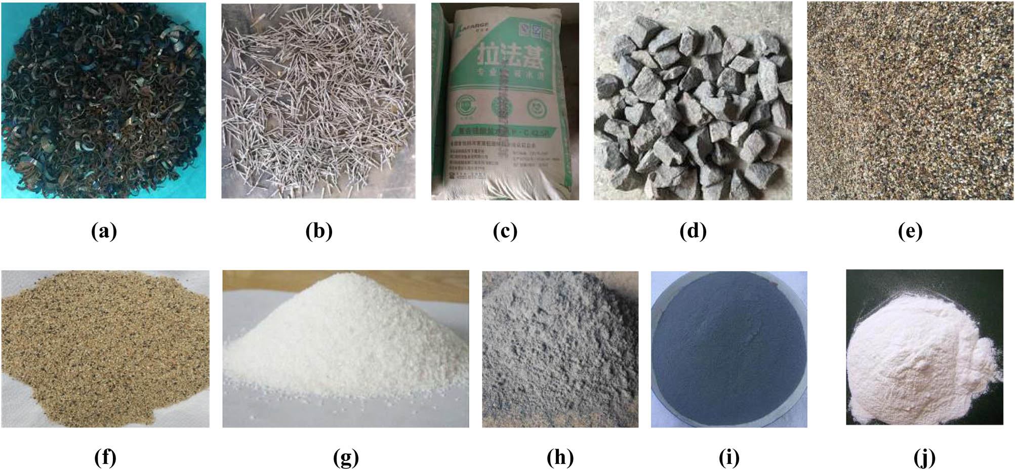
Composition of RSF-reinforced concrete. (a) RSF. (b) PSF. (c) Cement. (d) Crushed stone. (e) Bean stone (f). Natural sand. (g) Quartz sand. (h) Fly ash. (i) Silica fume. (j) Superplasticizer.
Concrete mix proportion
| Test piece no | Material consumption per unit volume (kg·m−3) | ||||||||
|---|---|---|---|---|---|---|---|---|---|
| Cement | Sand | Aggregate | Fly ash | Silica fume | Water | Superplasticizer | SF | ||
| PSF | RSF | ||||||||
| NC | 421 | 567 | 1,175 | 34 | 33 | 167 | 3 | 0 | 0 |
| PSFC1.0 | 421 | 567 | 1,175 | 34 | 33 | 167 | 3 | 80 | 0 |
| RSFC0.25 | 421 | 567 | 1,175 | 34 | 33 | 167 | 3 | 0 | 20 |
| RSFC0.5 | 421 | 567 | 1,175 | 34 | 33 | 167 | 3 | 0 | 40 |
| RSFC0.75 | 421 | 567 | 1,175 | 34 | 33 | 167 | 3 | 0 | 60 |
| RSFC1.0 | 421 | 567 | 1,175 | 34 | 33 | 167 | 3 | 0 | 80 |
| RSFC1.25 | 421 | 567 | 1,175 | 34 | 33 | 167 | 3 | 0 | 100 |
| RSFC1.5 | 421 | 567 | 1,175 | 34 | 33 | 167 | 3 | 0 | 150 |
2.2 Sample preparation and curing
In order to avoid the possibility of oil reducing the adhesion between RSF and concrete, the RSF with oil is removed during sorting, and cleaning the mixed oil and sawdust, and then the concrete mixture is mixed. In order to prevent twining and agglomeration of RSF in concrete, RSF is added to concrete mixture in 3 batches and 4 layers. Finally, the mixture is placed into the plastic mold coated with waste oil in advance. After the mixture is tamped, it is placed on a plate vibrator and vibrated tightly. The surface is covered with plastic film by vibration. It is demolded after standing at room temperature for 24 h. The demolded test block is put into water for curing (Figure 2) until it reaches the age of 28 days and taken out for test. The requirements of reference [33] for performance test of concrete mixture and strength test of test block: cube compressive and splitting resistance test block size is 150 mm × 150 mm × 150 mm, the size of the bending test block is 150 mm × 150 mm × 400 mm, and axial compression test block is 150 mm × 150 mm × 300 mm.
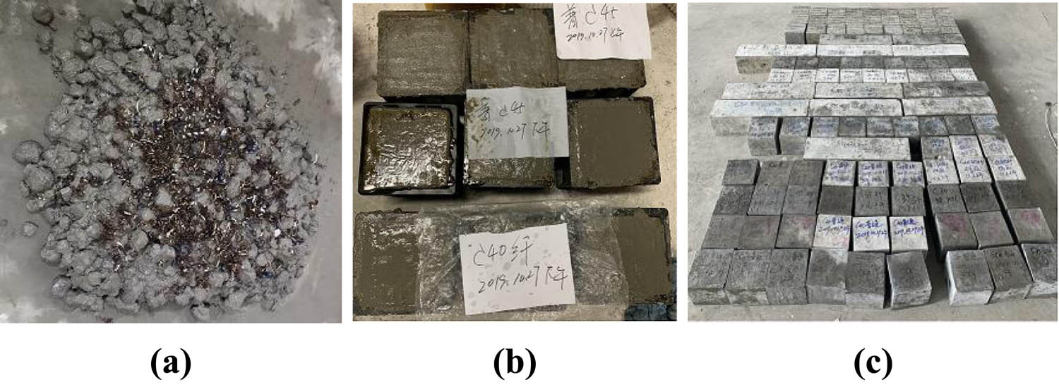
Fabrication process of test block: (a) mixture mixing, (b) molding, and (c) curing completed.
2.3 Test process
2.3.1 Slump test
After mixing the RSF mixture evenly, the slump of the mixture is tested with different mix proportions within 5 min. The mixture is filled into the slump cylinder three times, each time 1/3 of the height of the filling cylinder. During filling, the tamping rod is used to tamp evenly for 25 times. After the slump cylinder is filled with the mixture, the surface is smoothed, the slump cylinder is lifted vertically and rapidly, and the slump value is measured as soon as possible with a ruler (Figure 3).
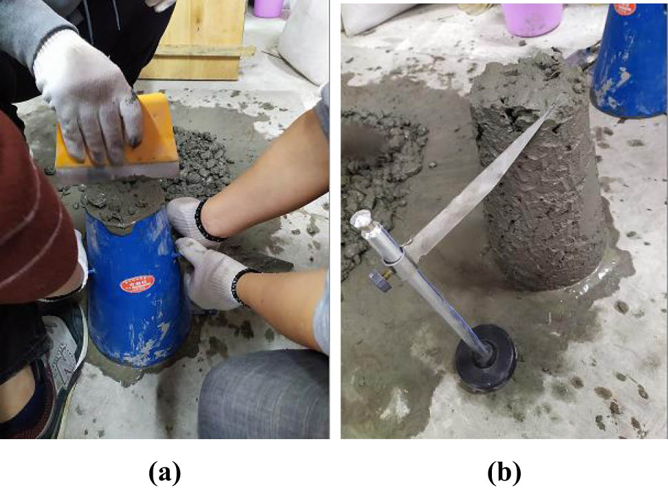
Slump test: (a) filling slump cylinder and (b) testing the slump.
2.3.2 Cube compressive strength test
WS-2000B microcomputer-controlled electro-hydraulic servo testing machine (Figure 4) is used for cube compression test. The cube compression test rate is set as 0.5 MPa·s−1 in references and specifications. The test results are taken as the average compression value of three samples in each group. The calculation formula of cube compressive strength of RSF-reinforced concrete is shown in the formula (1), and the calculation accuracy is 0.1 MPa.
where f cu is the cube compressive strength of RSFC (MPa), F is the ultimate compressive load of cube (N), and A is the compressive area of steel-reinforced concrete cube (mm2).
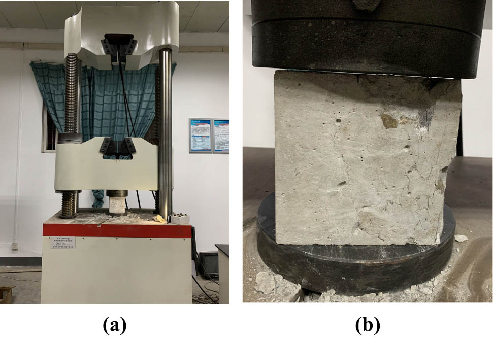
Cube compression test: (a) test device and (b) test process.
2.3.3 Splitting tensile strength test
A wooden board is installed at the bottom of the concrete test block to ensure the constancy of the test block during the test, as shown in Figure 5, to ensure that the top surface does not swing and the pressure is uniform. The loading speed is set to 0.05 MPa·s−1. Since the concrete specimen in this test is 150 mm × 150 mm × 150 mm standard test block, the splitting tensile strength is calculated according to the formula (2), and the calculation accuracy is 0.1 MPa [34].
where f ts, F, and A are the splitting tensile strength of concrete (MPa), splitting failure load (N), and bearing area of the splitting (mm2).
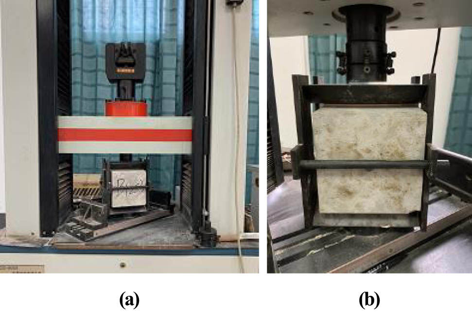
Splitting tensile strength test: (a) test device and (b) test process.
2.3.4 Flexural strength test
The four point flexural strength test adopts YA-300 microcomputer hydraulic pressure testing machine (Figure 6a). The bottom surface of the test piece is placed on the support, each end of the support extends 50 mm, and the top surface of the test block is 100 mm away from the support. The loading rate is 0.08 kN·s−1. Figure 6(b) is the loading diagram. The flexural strength of the test piece is calculated according to the formula (3), and the calculation accuracy is 0.1 MPa [35].
where f f , F, b, and h are flexural strength of concrete (MPa), maximum load at failure of specimen (N), and l is bearing spacing (mm), section width of test piece (mm), and section height of test piece (mm).
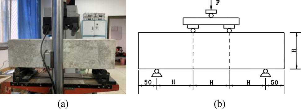
Four-point bending strength test equipment: (a) loading device and (b) schematic loading diagram.
2.3.5 Axial compressive strength
The axial compression test of prism is completed on the DYE-5000 elector-hydraulic pressure testing machine (Figure 7), which can complete the drawing of the full stress–strain curve of RSF-reinforced concrete. The full stress–strain curve of the whole test is loaded with equal strain control of 0.18 mm·min−1. The axial pressure and longitudinal deformation of the test block during the test are automatically collected by the computer. The pressure bearing plate on the test machine is equipped with a displacement meter to measure the longitudinal compression of the whole test block, and two displacement meters are installed in the middle of the test block to measure the longitudinal compression within 167 mm. The axial compressive strength of concrete prism is calculated by the formula (4), and the calculation accuracy is 0.1 MPa.
where f cp, F, and A are axial compressive strength of concrete (MPa), maximum load at failure of specimen (N), and bearing area of test piece (mm2).
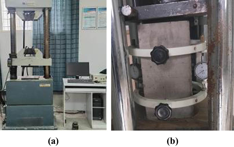
Prismatic axial compression testing machine: (a) loading device and (b) axial compression deformation measurement.
3 Test results and discussion
3.1 Performance of concrete mixture
3.1.1 Slump
The difference between the height of the slump cylinder and the height of the highest point of the concrete specimen after collapse is the slump of the concrete. The slump of mixtures with different mix proportions is shown in Figure 8. The slump of normal concrete (NC) is 95.7 mm, the slump decreased by 7.1, 15.8, 22.3, 24.9, 32.4, and 38.9%, respectively, compared with NC for RSFC0.25, RSFC0.5, RSFC0.75, RSFC1.0, RSFC1.25, and RSFC1.5. The slump of PSFC1.0 decreased by 23.6% compared with NC, the decline in slump value of PSFC1.0 and RSFC1.0 compared with NC is close but the value of RSFC1.0 is slightly smaller than that of PSFC1.0, indicating that RSF has a slightly greater impact on the slump of the mixture than PSF. In general, the slump of the mixture decreases significantly with the increase in the content of RSF. The reason is that the larger the volume content of RSF, the more cement mortar is wrapped on the surface of RSF, which reduces the slump of concrete. In addition, because RSF is spiral, a three-dimensional grid spatial structure is formed inside the concrete [36,37]. The adhesion between cement mortar and RSF is enhanced, and the flow of concrete is prevented. Therefore, the slump of the mixture is significantly reduced.
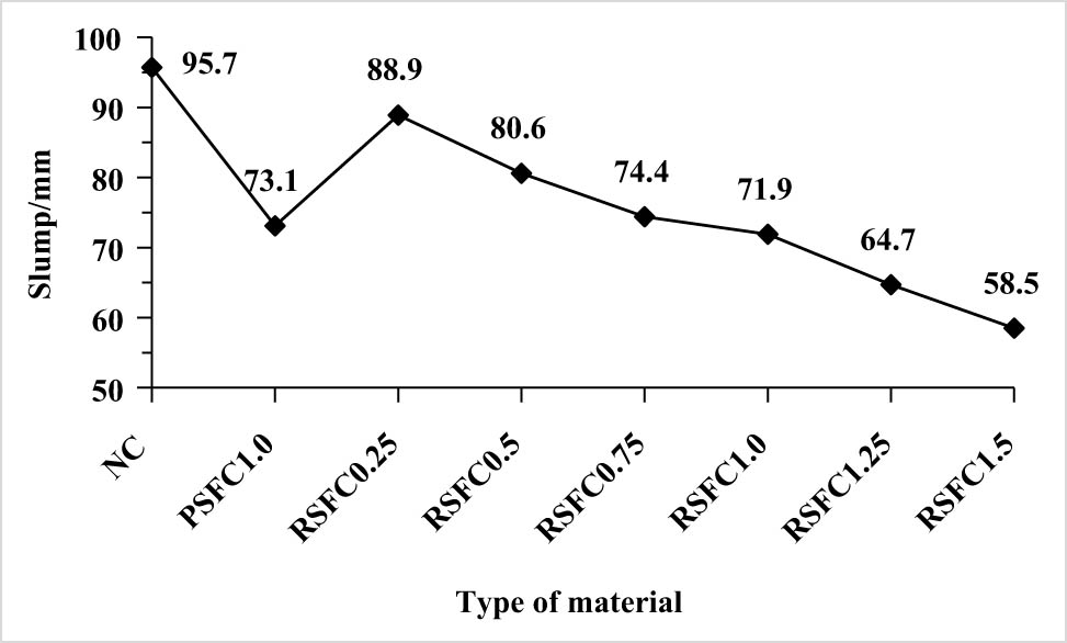
Slump of concrete mixture.
3.1.2 Gas content
The air content of concrete mixture is calculated according to the formula (5), and the actual air content of concrete mixture with different mix proportions is shown in Figure 9.
where A, A 0, and A g are the air content of concrete mixture, uncorrected air content of concrete mixture, and air content of aggregate, A g = 23%.
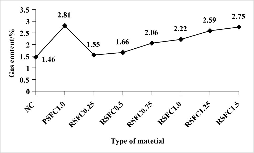
Air content of concrete mixture.
Figure 9 shows that the air content of ordinary concrete NC is 1.46%, the gas content of RSFC0.25, RSFC0.5, RSFC0.75, RSFC1.0, RSFC1.25, and RSFC1.5 increased by 6.2, 13.7, 41.1, 52.1, 77.4, and 92.4% compared with NC, respectively. The gas content of PSFC1.0 is 92.5%, which is higher than that of NC. The decline in PSFC1.0 and RSFC1.0 compared with NC is close and the gas content of PSFC1.0 is slightly larger than that of RSFC1.0, indicating that RSF has a slightly smaller impact on the gas content of the mixture than PSF. In general, the air content of concrete mixture increases with the increase in RSF volume content. The reason is that the addition of RSF forms more joint surfaces between concrete and cement mortar, which provide more paths for gas to enter, thus increasing the air content of concrete. In addition, the influence of PSF and RSF with the same volume content on the air content of concrete is similar, which shows that although RSF forms a three-dimensional spatial skeleton in concrete in a spiral shape [38], its bonding tightness with cement mortar is not much different from PSF, and the density of the formed gas channel is similar.
3.2 Cube compressive strength
Figure 10 shows the compressive strength of concrete test blocks with different mix proportions at 28 days. The 28-day cube compressive strength of NC is 41.7 MPa, the cube compressive strength of RSFC0.25, RSFC0.5, RSFC0.75, RSFC1.0, RSFC1.25, and RSFC1.5 increased by 8.2, 9.8, 12, 13.4, 15.3, and 15.8% compared with NC, respectively. The cube compressive strength of PSFC1.0 is 11.8% higher than that of NC. Compared with NC, the lifting amplitude of PSFC1.0 and RSFC1.0 is close and the lifting amplitude of PSFC1.0 is slightly smaller than that of RSFC1.0, indicating that RSF has a greater impact on the compressive strength of concrete cube than PSF. With the increase in RSF volume content, the cube compressive strength of RSFC generally shows an upward trend, but when the content of RSF exceeds 1.0%, the strength growth becomes very slow. When the content is less than 0.75%, although the growth rate is increasing, the growth rate is small. Therefore, it can be judged that the better volume content of RSF is 1.0%.
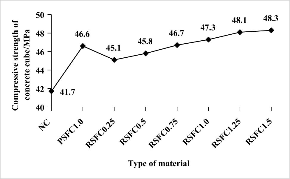
Cube compressive strength.
Figure 11 shows the compressive failure modes of three types of concrete cubes: NC, RSFC, and PSFC. From the analysis of failure mode, the failure mode of NC is inverted conical and brittle, while the failure modes of PSFC and RSFC are relatively similar, showing the failure mode of “crack without separation” and good ductility. Comparing the failure modes of PSFC and RSFC, the distribution and trend of cracks are similar, but the cracks of RSFC are thinner and more dense than those of PSFC, indicating that RSFC has better ductility. The reason is the existence of SF, which connects the cement mortar in the concrete and prevents the development of micro cracks in the concrete. Therefore, the failure mode of SFC is ductile failure and NC is brittle failure. Because the shape of RSF is spiral, it forms a three-dimensional spatial grid structure with cement mortar inside the concrete, and the “bridging” effect and “stitching” effect formed in the concrete are stronger than PSF [39]. Therefore, the crack width of RSFC is finer than PSFC, because of which the ductility of concrete is better. By observing the fracture of the sample, it is found that there is no obvious fiber fracture in both RSF and PSF, indicating that the tensile strength of RSF is similar to that of PSF.
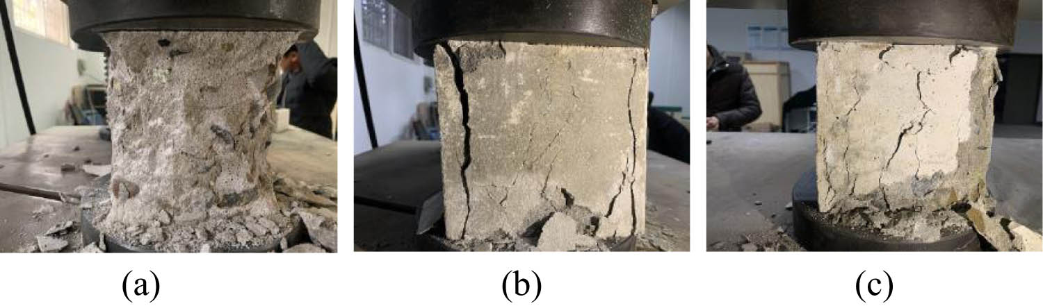
Failure mode of cube compressive strength: (a) NC, (b) PSFC, and (c) RSFC.
3.3 Splitting tensile strength
Because the concrete flexural member produces tensile stress in the concrete on the tensile side, it will lead to concrete cracking. Therefore, the study of concrete tensile strength has practical engineering significance for controlling concrete cracking.
Figure 12 shows the splitting tensile strength of each type of concrete. The splitting tensile strength of NC is 1.8 MPa, the splitting tensile strength of RSFC0.25, RSFC0.5, RSFC0.75, RSFC1.0, RSFC1.25, and RSFC1.5 increased by 57.7, 73.9, 82.7, 123.9, 125.6, and 126.7% compared with NC, respectively. The splitting tensile strength of PSFC1.0 is 128.3% higher than that of NC, the lifting amplitude of PSFC1.0 and RSFC1.0 is close and the lifting amplitude of PSFC1.0 is slightly larger than that of RSFC1.0, indicating that RSF has less effect on the splitting tensile strength of concrete than PSF. In general, the splitting tensile strength of concrete increases significantly with the increase in the volume content of RSF. The reason is that RSF is spiral and different in length. The three-dimensional spatial grid structure formed in the concrete forms a good “bridging” effect with cement mortar, which produces a “suture” effect on the cracking of concrete and delays the cracking speed of concrete tensile zone. It enhances the ductility of concrete [40]. When the volume content is 1.0%, the improvement effect of PSF on the splitting tensile strength of concrete is close to that of RSF. Due to RSF, the reason is that the tensile strength of PSF is higher than RSF. The length of PSF is uniform and longer than RSF, and the overall effect is close. In addition, when the volume content of RSF is less than 1.0%, the growth range of splitting tensile strength of concrete is more obvious, while when the volume content of RSF is greater than 1.0%, the growth range of splitting tensile strength of concrete is significantly slowed down. Therefore, when adding RSF to concrete to improve the ductility of concrete, the more the content, the better. It can be seen from the analysis of Figure 13, that the optimal volume content of RSF is about 1.0%.
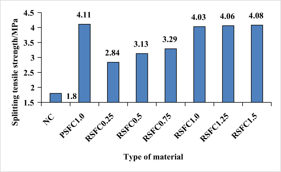
Splitting tensile strength of concrete.
Failure mode of splitting tensile strength of concrete: (a) NC, (b) PSFC, and (c) RSFC.
Figure 13 shows the failure mode of splitting tensile strength test specimens of different types of concrete. The failure mode of NC is mainly a wide vertical crack, with very few small cracks around, and the crack width is larger than PSFC and RSFC, which is characterized by brittle failure. In addition to a vertical crack, several small oblique cracks are distributed around PSFC, showing the characteristics of ductile failure. The failure mode of RSFC is similar to that of PSFC, but the lower half of the vertical crack is inclined, and the surrounding oblique fine cracks extend to the surface of the concrete test block, showing ductile failure. The test shows that adding RSF to concrete has an improvement effect similar to that of PSF, and can increase the ductility of concrete when it is damaged.
Whether it is PSF or RSF, there are two main reasons for cracks in concrete, that is, under the action of pressure, the bonding interface between cement mortar and coarse aggregate cracks, and the interface between steel fiber and cement mortar cracks.
3.4 Flexural strength
Figure 14 shows the flexural strength of each type of concrete. The flexural strength of NC is 7.9 MPa, the flexural strength of RSFC0.25, RSFC0.5, RSFC0.75, RSFC1.0, RSFC1.25, and RSFC1.5 increased by 20.3, 36.7, 41.8, 75.9, 78.5, and 79.7% compared with NC, respectively. The flexural strength of PSFC1.0 is 82.3% higher than that of NC. Compared with NC, PSFC1.0 has a significant increase in the lifting range than that of RSFC1.0, indicating that RSF has less effect on the flexural strength of concrete than PSF. In general, the flexural strength of concrete increases significantly with the increase in the volume content of RSF. It is analyzed that the reason is that the shape of RSF is spiral and forms a three-dimensional framework with the cement mortar in the concrete, which prevents the generation and development of internal cracks when the concrete is pulled, and the friction resistance caused by pulling RSF out of the concrete under tension is large. It consumes more external energy and delays the speed of concrete tensile failure [41]. When the volume content is 1.0%, the enhancement effect of PSF on the flexural strength of concrete is higher than that of RSF. The reason is that the shape of PSF is wavy and the tensile strength is higher than that of RSF. Its bite force with concrete is greater than that of RSF and concrete, which can consume more external effects. In addition, when the volume content of RSF is less than 1.0%, the increase in the flexural strength of concrete is more significant, while when the volume content of RSF is greater than 1.0%, the increase in the flexural strength of concrete is significantly reduced. Therefore, adding more RSF to concrete does not necessarily improve the flexural strength.
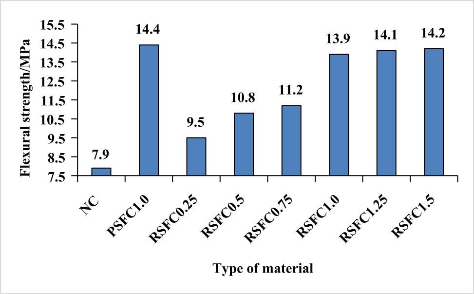
Flexural strength of concrete.
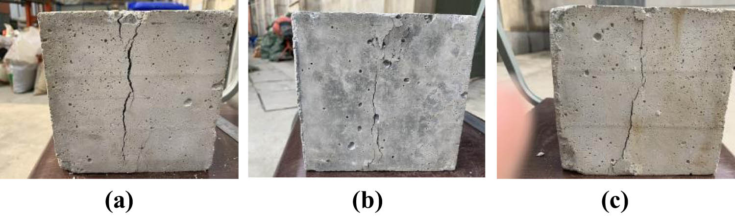
The crack development of different types of concrete under flexural failure is shown in Figure 15. During the failure of NC specimen, there is a vertical crack along the cross section. There are almost no small cracks extending outward around the crack. The crack trend is almost perpendicular to the long axis of the specimen. There is no obvious sign in the failure process, and the concrete around the crack does not peel off obviously. The failure presents obvious brittle characteristics, and the sound during failure is crisp. When the PSFC specimen is damaged, the cracks are generally distributed obliquely and in a broken line shape along the length direction. Small cracks with different widths are distributed around. The extension direction of small cracks has no obvious law. After the specimen is damaged, there are concrete spalling of different sizes along both sides of the main crack, and the specimen failure has ductility characteristics. The failure mode of RSFC is basically the same as that of PSFC, except that the crack width of the test piece is smaller than that of PSFC. When the test piece is damaged, it makes a “hissing” sound, which should be caused by the friction of the fiber pulled out of the concrete [42]. The reason is that the addition of steel fiber leads to the slow and worse regularity of the development and extension of cracks in concrete, which provides resistance to the development of cracks. Therefore, the specimens show obvious ductility during failure.
Failure mode of concrete flexural strength: (a) NC, (b) PSFC, and (c) RSFC.
3.5 Axial compressive strength
Figure 16 shows the axial compressive strength of each type of concrete. The axial compressive strength of NC is 24.3 MPa. The axial compressive strength of RSFC0.25, RSFC0.5, RSFC0.75, RSFC1.0, RSFC1.25, and RSFC1.5 increased by 4.9, 8.6, 14.4, 16.5, 17.7, and 17.7%, respectively compared with NC. The axial compressive strength of PSFC1.0 is 16.1% higher than that of NC. Compared with RSFC1.0, the lifting range of PSFC1.0 is lower than that of NC, but only by 0.4% decline, which is not obvious, indicating that RSF has a slightly greater impact on the axial compressive strength of concrete than PSF. In general, the axial compressive strength of concrete increases significantly with the increase in the volume content of RSF. The reason is that the shape of RSF is irregular, forming three-dimensional spatial structures in different directions in the concrete, preventing the generation and development of cracks in the concrete under pressure, improving the axial compressive strength of concrete and the ductility of concrete when damaged [43,44]. When the volume content of RSF is less than 1.0%, the increase in the concrete axial compressive strength is more significant, while when the volume content of RSF is more than 1.0%, the increase in concrete axial compressive strength is significantly reduced. Therefore, it can be judged that it is reasonable when the RSF content in concrete is about 1.0%, which is generally consistent with the conclusion of the above test.
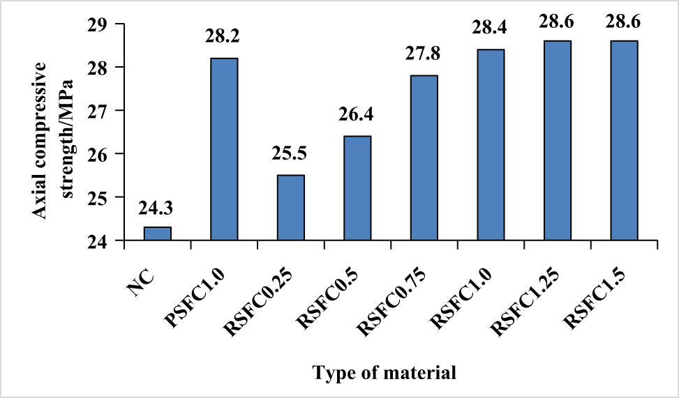
Failure mode of concrete axial compressive strength.
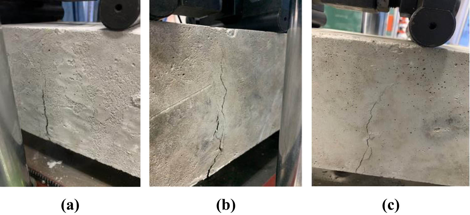
Figure 17 shows the axial compressive failure patterns of different types of concrete. After the test pressure reaches the peak value, the NC specimen breaks down rapidly. Due to the very short time of the failure process, the specimen will collapse without any bond, showing an obvious form of brittle failure. When the specimen cracks, the crack trend extends along the longitudinal direction of the specimen. When PSFC is damaged, the concrete in the middle of the specimen falls off seriously, and the overall shape is funnel-shaped. When the specimen is damaged, the crack trend is oblique to the longitudinal axis, and the concrete falls off seriously. When the RSFC specimen is damaged, the cracks are distributed obliquely, a large number of small cracks are distributed around the main crack, the concrete spalling is less, and the integrity of the specimen is good.
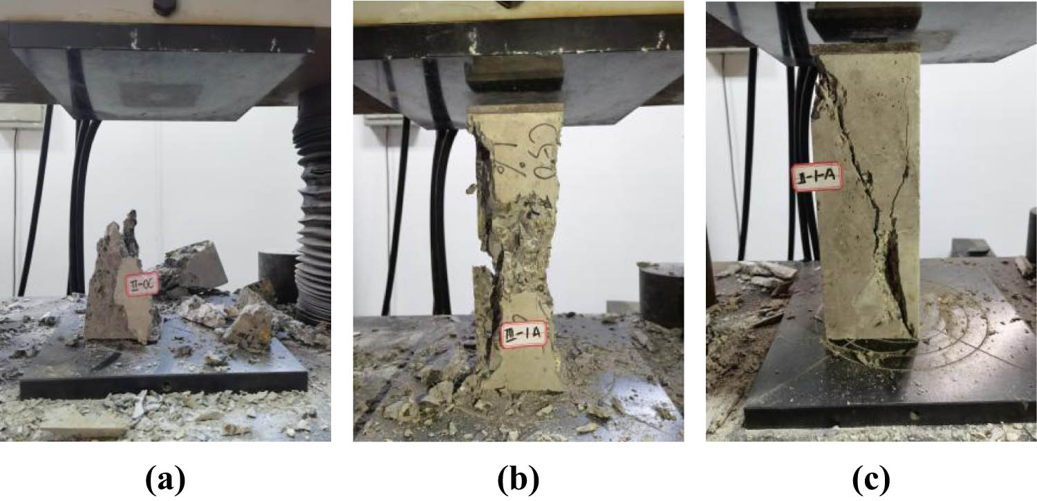
Failure mode of concrete axial compressive strength: (a) NC, (b) PSFC, and (c) RSFC.
PSFC and RSFC specimens did not completely collapse longitudinally during failure, showing obvious ductile failure. The reason is that SFs can always be closely bonded with cement mortar during the stress process of the specimen. When the specimen is damaged, the formation of internal cracks of the concrete are prevented by SF. SF hinders the generation and development of cracks in the concrete. After the cracks are developed, SF has joint cooperation with the cracks. To destroy the concrete, SF must be pulled out from its interior first. This consumes the effect applied on the concrete specimen and delays the cracking of the concrete. When the concrete is damaged, the SF that is not completely pulled out of the concrete is bonded with concrete stripping bodies of different sizes to varying degrees, so that the approximate shape of the specimen can be maintained. Therefore, the concrete specimen presents the characteristics of plastic failure.
3.6 Toughness evaluation
Figure 18 shows the toughness curves of different types of concrete. The toughness index is calculated according to the provisions in the literature [45]. After adding RSF to the concrete, the toughness curve shows an obvious downward section, and the downward section of the curve is more gentle with the increase in the RSF volume content. ASTM C1018 toughness index method is the characteristic point method [46,47], using the ideal elastic-plastic body as the reference, and the deflection corresponding to the initial crack as the key deflection and characteristic point (3δ, 5.5δ, and 10.5δ). The ratio of deflection is taken as the toughness index (I 5, I 10, and I 20) of the material, and I 5, I 10, and I 20 are calculated according to the formulas (6)–(8), respectively.
where A 1–A 4 is the area enclosed under the curve under the deflection of δ, 3δ, 5.5δ, and 10.5δ, respectively.
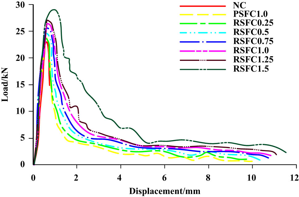
Concrete toughness curve.
The flexural toughness index of various types of concrete calculated according to ASTM C1018 is shown in Figure 19. The bending toughness index of NC is 1.62, the toughness index (I 5, I 10, and I 20) of RSFC0.25, RSFC0.5, RSFC0.75, RSFC1.0, RSFC1.25, and RSFC1.5 is higher than that of NC, and the toughness index of concrete is increasing with the increase in the RSF volume content. The toughness index (I 5, I 10, and I 20) of RSFC1.5 is 195.1, 411.2, and 538.3% higher than that of NC, respectively. The reason is that RSF is pulled out of the cement mortar matrix when the concrete is stressed, which consumes a lot of energy, delays the material fracture process, and produces a significant toughening effect. In addition, when the volume content is 1.0%, the toughness of PSFC1.0 is little higher than that of RSFC1.0, because the strength and elastic modulus of PSF are larger than RSF, so the pull-out energy after bonding with concrete is stronger than RSF and can consume more energy.
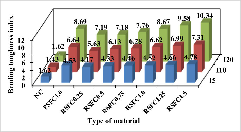
Flexural toughness index of concrete.
4 Conclusion
Through the research and analysis of the mix proportion, slump, strength, and toughness of RSFC, the following conclusions are obtained:
The slump of RSFC decreases with the increase in the RSF volume content. When the volume content of RSFC is 0.25–1.5%, the slump is 7.1–38.9% lower than that of NC, indicating that the influence of RSF on the flow performance of concrete is stronger than that of PSF. The gas content of PSFC and RSFC is higher than that of NC. The gas content increases with the increase in the RSF volume content.
The compressive strength of concrete increases with the increase in the RSF volume content, and 1.0% is the reasonable volume content of RSF. The cube compressive strength and axial compressive strength of RSFC1.0 are increased by 16.3 and 16.5%, respectively, compared with NC. The strengthening effect of PSFC1.0 on the compressive strength of concrete is lower than that of RSFC. The cube compressive strength and axial compressive strength at the age of 28 days are increased by 11.8 and 16.1%, respectively, compared with NC.
The splitting tensile strength and flexural strength of RSFC and PSFC are higher than those of NC, and increase with the increase in the RSF volume content. The splitting tensile strength and flexural strength of RSFC1.5 are 126.7 and 79.7% higher than NC, respectively, and the splitting tensile strength and flexural strength of PSFC1.0 are 128.3 and 82.3% higher than NC, respectively.
RSF can significantly enhance the toughness of concrete, and the flexural toughness index of concrete increases with the increase in the RSF volume content. When the volume content is 1.0%, the toughening effect of PSF on the concrete is slightly better than that of RSF.
Acknowledgments
Thank professor Xu Qiang and state key laboratory of geohazard prevention and geoenvironment protection for their guidance.
-
Funding information: This study was supported by the National Natural Science Foundation of China (Grant No. 41172327), Open Fund Declaration of State Key Laboratory of Geohazard Prevention and Geoenvironment Protection, Chengdu University of Technology (Grant No. SKLGP2019K019), and Sichuan Provincial Research and Development program (Grant No. 2020YFS0061).
-
Author contributions: Yongtao Gao, Bin Wang, and Changjiang Liu wrote the article. David Hui, Qiang Xu, Qihua Zhao, Jiachen Wei, and Xiaoyu Hong checked the manuscript.
-
Conflict of interest: One of the co-authors – Prof. David Hui – is an Editor in Chief of Reviews on Advanced Materials Science.
-
Data availability statement: All data generated or analyzed during this study are included in this published article or are available from the corresponding author on reasonable request.
References
[1] Adomako, S., C. J. Engelsen, R. T. Thorstensen, and D. M. Barbieri. Repeated load triaxial testing of recycled excavation materials blended with recycled phyllite. Materials, Vol. 15, 2022.10.3390/ma15020621Search in Google Scholar PubMed PubMed Central
[2] Adomako, S., C. J. Engelsen, R. T. Thorstensen, and D. M. Barbieri. Review of the relationship between aggregates geology and Los Angeles and micro-Deval tests. Bulletin of Engineering Geology and the Environment, Vol. 80, 2021, pp. 1963–1980.10.1007/s10064-020-02097-ySearch in Google Scholar
[3] Navid, R. and M. Z. Zhang. Fiber-reinforced geopolymer composites: A review. Cement and Concrete Composites, Vol. 107, 2020, id. 103498.10.1016/j.cemconcomp.2019.103498Search in Google Scholar
[4] Fraj, A. B. and R. Idir. Concrete based on recycled aggregates-recycling and environmental analysis: a case study of Paris’ region. Construction and Building Materials, Vol. 157, 2017, pp. 952–964.10.1016/j.conbuildmat.2017.09.059Search in Google Scholar
[5] Liu, C. J., X. C. Huang, Y. Y. Wu, X. W. Deng, and Z. L. Zheng. The effect of graphene oxide on the mechanical properties, impermeability and corrosion resistance of cement mortar containing mineral admixtures. Construction and Building Materials, Vol. 288, 2021, id. 123059.10.1016/j.conbuildmat.2021.123059Search in Google Scholar
[6] Reiterman, P., O. Holčapek, O. Zobal, and M. Keppert. Freeze-thaw resistance of cement screed with various supplementary cementitious materials. Reviews on Advanced Materials Science, Vol. 581, 2019, pp. 66–74.10.1515/rams-2019-0006Search in Google Scholar
[7] Amer, A. A. A., K. Ezziane, A. Bougara, and M. Adjoudj. Rheological and mechanical behavior of concrete made with pre-saturated and dried recycled concrete aggregates. Construction and Building Materials, Vol. 123, 2016, pp. 300–308.10.1016/j.conbuildmat.2016.06.107Search in Google Scholar
[8] Sevinc, A. H. and M. Y. Durgun. Properties of high-calcium fly ash-based geopolymer concretes improved with high-silica sources. Construction and Building Materials, Vol. 261, 2020, id. 120014.10.1016/j.conbuildmat.2020.120014Search in Google Scholar
[9] Wang, J. Study on preparation and mechanical properties of waste grade spiral steel fiber concrete, Chengdu: Chengdu university of technology; 2020. pp. 47–53.Search in Google Scholar
[10] Kong, X. Q., W. C. He, L. L. Xing, and X. Z. Wang. Effect of steel fiber-polypropylene fiber hybrid additon on impact resistance of recycled aggregate concrete. Acta Materiae Compositae Sinica, Vol. 37, No. 7, 2020, pp. 1763–1773.Search in Google Scholar
[11] Chen, M., H. Si, X. Fan, Y. Xuan, and M. Zhang. Dynamic compressive behaviour of recycled tyre steel fiber reinforced concrete. Construction and Building Materials, Vol. 316, 2021, id. 125896.10.1016/j.conbuildmat.2021.125896Search in Google Scholar
[12] Weber, F., J. Orben, A. Haus, and S. Anders. Concrete technological influences on the performance classes of steel fibre concrete. Beton-und Stahlbetonbau, Vol. 116, No. S1, 2021, pp. 36–47.10.1002/best.202100011Search in Google Scholar
[13] Cagglano, A., P. Folino, C. Lima, E. Martinelli, and M. Pepe. On the mechanical response of hybrid fiber reinforced concrete with recycled and industrial steel fibers. Construction and Building Materials, Vol. 147, 2017, pp. 286–295.10.1016/j.conbuildmat.2017.04.160Search in Google Scholar
[14] Jin, R., B. Li, A. Elamin, S. H. Wang, O. Tsioulou, and D. Wanatowski. Experimental investigation of properties of concrete containing recycled construction wastes. International Journal of Civil Engineering, Vol. 16, 2018, pp. 1621–1633.10.1007/s40999-018-0301-4Search in Google Scholar
[15] Pawelska-Mazur, M. and M. Kaszynska. Mechanical performance and environmental assessment of sustainable concrete reinforced with recycled end-of-life tyre fibers. Materials, Vol. 14, No. 2, 2021, id. 256.10.3390/ma14020256Search in Google Scholar PubMed PubMed Central
[16] Liu, C. J., X. C. Huang, Y. Y. Wu, X. W. Deng, J. Liu, and Z. L. Zheng. Review on the research progress of cement-based and geopolymer materials modified by graphene and graphene oxide. Nanotechnology Reviews, Vol. 91, 2020, pp. 155–169.10.1515/ntrev-2020-0014Search in Google Scholar
[17] Letelier, V., E. Tarela, P. Muñoz, and G. Moriconi. Combined effects of recycled hydrated cement and recycled aggregates on the mechanical properties of concrete. Construction and Building Materials, Vol. 132, 2017, pp. 365–375.10.1016/j.conbuildmat.2016.12.010Search in Google Scholar
[18] Ganesh, A. C. and M. Muthukannan. Development of high performance sustainable optimized fiber reinforced geo-polymer concrete and prediction of compressive strength. Journal of Cleaner Production, Vol. 282, 2021, id. 124543.10.1016/j.jclepro.2020.124543Search in Google Scholar
[19] Machin, E. B., D. T. Pedroso, and J. A. De Carvalho. Energetic valorization of waste tires. Renewable & Sustainable Energy Reviews, Vol. 68, 2017, pp. 306–315.10.1016/j.rser.2016.09.110Search in Google Scholar
[20] Isa, M. N., K. Pilakoutas, M. Guadagnini, and H. Angelakopoulos. Mechanical performance of affordable and eco-efficient ultra-high performance concrete (UHPC) containing recycled tyre steel fibers. Construction and Building Materials, Vol. 255, 2020, id. 119272.10.1016/j.conbuildmat.2020.119272Search in Google Scholar
[21] Senesavath, S., A. Salem, S. Kashkash, B. Zehra, and Z. Orban. The effect of recycle tyre steel fibers on the properties of concrete. Pollack Period, Vol. 2021, 2021, pp. 1–7.10.1556/606.2021.00388Search in Google Scholar
[22] Sathiskumar, C. and S. Karthikeyan. Recycling of waste tires and its energy storage application of by-products—A review. Sustainable Materials and Technologies, Vol. 22, 2019, id. e00125.10.1016/j.susmat.2019.e00125Search in Google Scholar
[23] Bowles, A., G. Fowler, C. O’Sullivan, and K. Parker. Sustainable rubber recycling from waste tyres by waterjet: A novel mechanistic and practical analysis. Sustainable Materials and Technologies, Vol. 25, 2020, id. e00173.10.1016/j.susmat.2020.e00173Search in Google Scholar
[24] Thomas, B. S., S. Kumar, P. Mehra, R. C. Gupta, M. Joseph, and L. J. Csetenyi. Abrasion resistance of sustainable green concrete containing waste tire rubber particles. Construction and Building Materials, Vol. 124, 2016, pp. 906–909.10.1016/j.conbuildmat.2016.07.110Search in Google Scholar
[25] Zhang, Y. and L. Gao. Influence of tire-recycled steel fibers on strength and flexural behavior of reinforced concrete. Advanced Material Science and Engineering, Vol. 2020, 2020, pp. 6363105–7.10.1155/2020/6363105Search in Google Scholar
[26] Gupta, T., S. Chaudhary, and R. K. Sharma. Mechanical and durability properties of waste rubber fiber concrete with and without silica fume. Journal of Cleaner Production, Vol. 112, 2016, pp. 702–711.10.1016/j.jclepro.2015.07.081Search in Google Scholar
[27] Hu, H., P. Papastergiou, H. Angelakopoulos, M. Guadagnini, and K. Pilakoutas. Mechanical properties of SFRC using blended recycled tyre steel cords (RTSC) and recycled tyre steel fibers (RTSF). Construction and Building Materials, Vol. 187, 2018, pp. 553–564.10.1016/j.conbuildmat.2018.07.206Search in Google Scholar
[28] Ahmadi, M., S. Farzin, A. Hassani, and M. Motamedi. Mechanical properties of the concrete containing recycled fibers and aggregates. Construction and Building Materials, Vol. 144, 2017, pp. 392–398.10.1016/j.conbuildmat.2017.03.215Search in Google Scholar
[29] Matar, P. and G. P. Zehil. Effects of polypropylene fibers on the physical and mechanical properties of recycled aggregate concrete. Journal of Wuhan University of Technology – Materials Science Editor, Vol. 34, No. 6, 2019, pp. 1327–1344.10.1007/s11595-019-2196-6Search in Google Scholar
[30] Ali, B. and L. A. Qureshi. Influence of glass fibers on mechanical and durability performance of concrete with recycled aggregates. Construction and Building Materials, Vol. 228, 2019, id. 116783.10.1016/j.conbuildmat.2019.116783Search in Google Scholar
[31] Mastali, M., A. Dalvand, A. Sattarifard, Z. Abdollahnejad, and M. Illikainen. Characterization and optimization of hardened properties of self-consolidation concrete incorporation recycled steel, industrial steel, polypropylene and hybrid fibers. Composite part B: Engineering, Vol. 151, 2018, pp. 186–200.10.1016/j.compositesb.2018.06.021Search in Google Scholar
[32] Grzymski, F., M. Musial, and T. Trapko. Mechanical properties of fiber reinforced concrete with recycled fibers. Construction and Building Materials, Vol. 198, 2018, pp. 323–331.10.1016/j.conbuildmat.2018.11.183Search in Google Scholar
[33] Leone, M., G. Centonze, D. Colonna, F. Micelli, and M. Aiello. Fiber-reinforced concrete with low content of recycled steel fiber: Shear behaviour. Construction and Building Materials, Vol. 161, 2018, pp. 141–155.10.1016/j.conbuildmat.2017.11.101Search in Google Scholar
[34] Fan, X. C., G. Y. Li, M. Chen, and H. Wang. Experimental study on mechanical properties of recycled tyre steel fiber reinforced concrete. Concrete, No. 381, 2021, pp. 65–68.Search in Google Scholar
[35] Fan, X. C., W. J. Zhang, T. F. Liang, and K. F. Chen. Experimental study on basic mechanical properties of recycled tyre steel fiber reinforced aggregate concrete. Bulletin of the Chinese Ceramic Society, Vol. 40, No. 7, 2021, pp. 2331–2340.Search in Google Scholar
[36] Dhanapal, J. and S. Jeyaprakash. Mechanical properties of mixed steel fiber reinforced concrete with the combination of micro and macro steel fibers. Structural Concrete, Vol. 21, 2020, pp. 458–467.10.1002/suco.201700219Search in Google Scholar
[37] Simalti, A. and A. P. Singh. Comparative study on performance of manufactured steel fiber and shredded tire recycled steel fiber reinforced self-consolidating concrete. Construction and Building Materials, Vol. 266, 2021, id. 121102.10.1016/j.conbuildmat.2020.121102Search in Google Scholar
[38] Najim, K. B., A. Saeb, and Z. Al-Azzawi. Structural behaviour and fracture energy of recycled steel fibers self compacting reinforced concrete beams. Journal of Building Engineering, Vol. 17, 2018, pp. 174–182.10.1016/j.jobe.2018.02.014Search in Google Scholar
[39] Liu, C. J., X. He, X. W. Deng, Y. Y. Wu, Z. L. Zheng, and J. Liu. Application of nanomaterials in ultra-high performance concrete: a review. Nanotechnology Reviews, Vol. 912, 2020, pp. 1427–1444.10.1515/ntrev-2020-0107Search in Google Scholar
[40] Chen, M., H. Q. Si, X. C. Fan, Y. W. Yiwei Xuan, and M. Z. Zhang. Dynamic compressive behaviour of recycled tyre steel fibre reinforced concrete. Construction and Building Materials, Vol. 316, 2022, id. 125896.10.1016/j.conbuildmat.2021.125896Search in Google Scholar
[41] Sofi, A. Effect of waste tyre rubber on mechanical and durability properties of concrete: A review. Ain Shams Engineering Journal, Vol. 94, 2018, pp. 2691–2700.10.1016/j.asej.2017.08.007Search in Google Scholar
[42] Gigli, S., D. Landi, and M. Germani. Cost-benefit analysis of a circular economy project: a study on a recycling system for end-of-life tyres. Journal of Cleaner Production, Vol. 229, 2019, pp. 680–694.10.1016/j.jclepro.2019.03.223Search in Google Scholar
[43] Mastali, M., A. Dalvand, A. R. Sattarifard, and M. Illikainen. Development of ecoefficient and cost-effective reinforced self-consolidation concretes with hybrid industrial/recycled steel fibers. Construction and Building Materials, Vol. 166, 2018, pp. 214–226.10.1016/j.conbuildmat.2018.01.147Search in Google Scholar
[44] Chen, M., H. Zhong, L. Chen, Y. Zhang, and M. Zhang. Engineering properties and sustainability assessment of recycled fibre reinforced rubberised cementitious composite. Journal of Cleaner Production, Vol. 278, 2021, id. 123996.10.1016/j.jclepro.2020.123996Search in Google Scholar
[45] Gurusideswar, S., A. Shukla, K. N. Jonnalagadda, and P. Nanthagopalan. Tensile strength and failure of ultra-high performance concrete (UHPC) composition over a wide range of strain rates. Construction and Building Materials, Vol. 258, 2020, p. 119642.10.1016/j.conbuildmat.2020.119642Search in Google Scholar
[46] ASTM, C1018-97. Standard test method for flexural toughness and first-crack strength of fiber reinforced concrete, 1997.Search in Google Scholar
[47] Liew, K. M. and A. Akbar. The recent progress of recycled steel fiber reinforced concrete. Construction and Building Materials, Vol. 232, 2020, id. 117232.10.1016/j.conbuildmat.2019.117232Search in Google Scholar
© 2022 Yongtao Gao et al., published by De Gruyter
This work is licensed under the Creative Commons Attribution 4.0 International License.
Articles in the same Issue
- Review Articles
- State of the art, challenges, and emerging trends: Geopolymer composite reinforced by dispersed steel fibers
- A review on the properties of concrete reinforced with recycled steel fiber from waste tires
- Copper ternary oxides as photocathodes for solar-driven CO2 reduction
- Properties of fresh and hardened self-compacting concrete incorporating rice husk ash: A review
- Basic mechanical and fatigue properties of rubber materials and components for railway vehicles: A literature survey
- Research progress on durability of marine concrete under the combined action of Cl− erosion, carbonation, and dry–wet cycles
- Delivery systems in nanocosmeceuticals
- Study on the preparation process and sintering performance of doped nano-silver paste
- Analysis of the interactions between nonoxide reinforcements and Al–Si–Cu–Mg matrices
- Research Articles
- Study on the influence of structural form and parameters on vibration characteristics of typical ship structures
- Deterioration characteristics of recycled aggregate concrete subjected to coupling effect with salt and frost
- Novel approach to improve shale stability using super-amphiphobic nanoscale materials in water-based drilling fluids and its field application
- Research on the low-frequency multiline spectrum vibration control of offshore platforms
- Multiple wide band gaps in a convex-like holey phononic crystal strip
- Response analysis and optimization of the air spring with epistemic uncertainties
- Molecular dynamics of C–S–H production in graphene oxide environment
- Residual stress relief mechanisms of 2219 Al–Cu alloy by thermal stress relief method
- Characteristics and microstructures of the GFRP waste powder/GGBS-based geopolymer paste and concrete
- Development and performance evaluation of a novel environmentally friendly adsorbent for waste water-based drilling fluids
- Determination of shear stresses in the measurement area of a modified wood sample
- Influence of ettringite on the crack self-repairing of cement-based materials in a hydraulic environment
- Multiple load recognition and fatigue assessment on longitudinal stop of railway freight car
- Synthesis and characterization of nano-SiO2@octadecylbisimidazoline quaternary ammonium salt used as acidizing corrosion inhibitor
- Perforated steel for realizing extraordinary ductility under compression: Testing and finite element modeling
- The influence of oiled fiber, freeze-thawing cycle, and sulfate attack on strain hardening cement-based composites
- Perforated steel block of realizing large ductility under compression: Parametric study and stress–strain modeling
- Study on dynamic viscoelastic constitutive model of nonwater reacted polyurethane grouting materials based on DMA
- Mechanical behavior and mechanism investigation on the optimized and novel bio-inspired nonpneumatic composite tires
- Effect of cooling rate on the microstructure and thermal expansion properties of Al–Mn–Fe alloy
- Research on process optimization and rapid prediction method of thermal vibration stress relief for 2219 aluminum alloy rings
- Failure prevention of seafloor composite pipelines using enhanced strain-based design
- Deterioration of concrete under the coupling action of freeze–thaw cycles and salt solution erosion
- Creep rupture behavior of 2.25Cr1Mo0.25V steel and weld for hydrogenation reactors under different stress levels
- Statistical damage constitutive model for the two-component foaming polymer grouting material
- Nano-structural and nano-constraint behavior of mortar containing silica aggregates
- Influence of recycled clay brick aggregate on the mechanical properties of concrete
- Effect of LDH on the dissolution and adsorption behaviors of sulfate in Portland cement early hydration process
- Comparison of properties of colorless and transparent polyimide films using various diamine monomers
- Study in the parameter influence on underwater acoustic radiation characteristics of cylindrical shells
- Experimental study on basic mechanical properties of recycled steel fiber reinforced concrete
- Dynamic characteristic analysis of acoustic black hole in typical raft structure
- A semi-analytical method for dynamic analysis of a rectangular plate with general boundary conditions based on FSDT
- Research on modification of mechanical properties of recycled aggregate concrete by replacing sand with graphite tailings
- Dynamic response of Voronoi structures with gradient perpendicular to the impact direction
- Deposition mechanisms and characteristics of nano-modified multimodal Cr3C2–NiCr coatings sprayed by HVOF
- Effect of excitation type on vibration characteristics of typical ship grillage structure
- Study on the nanoscale mechanical properties of graphene oxide–enhanced shear resisting cement
- Experimental investigation on static compressive toughness of steel fiber rubber concrete
- Study on the stress field concentration at the tip of elliptical cracks
- Corrosion resistance of 6061-T6 aluminium alloy and its feasibility of near-surface reinforcements in concrete structure
- Effect of the synthesis method on the MnCo2O4 towards the photocatalytic production of H2
- Experimental study of the shear strength criterion of rock structural plane based on three-dimensional surface description
- Evaluation of wear and corrosion properties of FSWed aluminum alloy plates of AA2020-T4 with heat treatment under different aging periods
- Thermal–mechanical coupling deformation difference analysis for the flexspline of a harmonic drive
- Frost resistance of fiber-reinforced self-compacting recycled concrete
- High-temperature treated TiO2 modified with 3-aminopropyltriethoxysilane as photoactive nanomaterials
- Effect of nano Al2O3 particles on the mechanical and wear properties of Al/Al2O3 composites manufactured via ARB
- Co3O4 nanoparticles embedded in electrospun carbon nanofibers as free-standing nanocomposite electrodes as highly sensitive enzyme-free glucose biosensors
- Effect of freeze–thaw cycles on deformation properties of deep foundation pit supported by pile-anchor in Harbin
- Temperature-porosity-dependent elastic modulus model for metallic materials
- Effect of diffusion on interfacial properties of polyurethane-modified asphalt–aggregate using molecular dynamic simulation
- Experimental study on comprehensive improvement of shear strength and erosion resistance of yellow mud in Qiang Village
- A novel method for low-cost and rapid preparation of nanoporous phenolic aerogels and its performance regulation mechanism
- In situ bow reduction during sublimation growth of cubic silicon carbide
- Adhesion behaviour of 3D printed polyamide–carbon fibre composite filament
- An experimental investigation and machine learning-based prediction for seismic performance of steel tubular column filled with recycled aggregate concrete
- Effects of rare earth metals on microstructure, mechanical properties, and pitting corrosion of 27% Cr hyper duplex stainless steel
- Application research of acoustic black hole in floating raft vibration isolation system
- Multi-objective parametric optimization on the EDM machining of hybrid SiCp/Grp/aluminum nanocomposites using Non-dominating Sorting Genetic Algorithm (NSGA-II): Fabrication and microstructural characterizations
- Estimating of cutting force and surface roughness in turning of GFRP composites with different orientation angles using artificial neural network
- Displacement recovery and energy dissipation of crimped NiTi SMA fibers during cyclic pullout tests