Flame-retardant thermoelectric responsive coating based on poly(3,4-ethylenedioxythiphene) modified metal–organic frameworks
-
Guorong Wang
 ,
Zhiyuan Mei
,
Zhiyuan Mei

Abstract
Poly(3,4-ethylenedioxythiophene) (PEDOT) is introduced on the surface of a metal–organic framework material by solvothermal method to prepare nanorods (TE@Zn-MOFs) with both flame retardant and thermoelectric properties. Data from cone calorimeter and TG-IR show that TE@Zn-MOFs effectively improves the flame retardant and smoke suppression properties of epoxy-based coatings. At a high TE@Zn-MOFs content of 10 wt%, the coating oxygen index increased from 18.2% to 29.0%, the total smoke release decreased from 25.26 to 22.60 m2, and the V-0 level was achieved in vertical combustion classification. Moreover, PEDOT enables epoxy-based coatings to output a certain current value at different heating temperatures (50–200°C). This work demonstrates that MOFs with flexible and variable structures can serve as effective flame retardants for epoxy-based coatings and endow coatings with fire warning characteristics, providing a way to develop multifunctional coatings for different application scenarios.
1 Introduction
In recent years, ship fires and explosion accidents have been on the rise. As a water combat platform, ships have the characteristics of closed area, complex structure, changeable environment, dense personnel and goods, large numbers and high density of flammable and explosive goods [1–4]. These characteristics lead to a high incidence of fire on ships. According to statistics, ship fires account for about 15% of total fire losses in China [5–7]. Therefore, with the increasingly widespread application of flammable lightweight composite materials in ships, higher requirements have been put forward for the sensitivity of fire warning sensors. Current fire warning devices mainly include smoke alarms and infrared alarms [8,9], which are often installed at the top of the ceiling or on the wall, usually far from the ignition source, and can only be triggered when the smoke concentration or thermal infrared intensity exceeds a certain value. As a result, they often require a longer response time (>80 s) [8]. Lack of early warning systems and delays in early warning often result in people missing optimal firefighting and evacuation times. For example, the “Fleet Admiral Kuznetsov” caught fire while in port for maintenance; the “Kilsack” caught fire during routine maintenance. Many painful fire accidents remind us that the development of new highly sensitive fire warning sensors is the key to reducing fire incidence and fire losses.
Smart responsive materials can respond to external stimuli such as pressure, temperature and light by introducing specific functional molecules or groups [10–12]. This also provides a solution for the development of new fire warning devices. Thermoelectric materials are a type of functional material that can achieve the mutual conversion of thermal and electrical energy, and are generally semiconductor materials [13]. Thermoelectric materials can be divided into seven types, including BiTe series, SnSe series, CuSe series, multi-component oxides, half-Heusler alloys, germanium telluride, lead telluride series and organic–inorganic composite series [14].
Most inorganic thermoelectric materials contain expensive metals or toxic elements [15–17]. Compared with inorganic thermoelectric materials, organic thermoelectric materials have the advantages of low thermal conductivity, light weight, low toxicity, high flexibility, easy processing, etc. [18–20]. They are generally conductive polymers with conjugated structures, such as polyaniline, polypyrrole and poly (3,4-ethylenedioxythiophene) (PEDOT) [20]. These polymers have a variety of band structures, showing the characteristics of semiconductor materials. However, the key problem is that the ZT (thermoelectric figure of merit) value of organic thermoelectric materials is too small to meet practical application [21]. To improve the ZT value of these materials, many measures have been taken, such as doping [22], organic–inorganic hybridization [23] and post-treatment [24]. Metal–organic frameworks (MOFs) can be obtained by organic–inorganic hybrid treatment [25]. MOFs is an organic–inorganic hybrid nanoporous material, which has been applied in optics, medicine and electronics due to its flexible structure design and good dispersion [26–28]. In addition, studies have confirmed that MOFs as flame retardants in polymers can significantly improve their flame retardancy and smoke suppression properties [29–31].
Compared to additive flame retardants, flame retardant coatings effectively enhance the flame retardancy of the protected material without affecting its inherent properties, such as mechanical properties. As a general resin, epoxy resin has the advantages of high strength, wear resistance, corrosion resistance and strong adhesion, and is widely used in plastic parts, coating substrates and other fields. However, as a flame-retardant coating, unmodified epoxy resin often fails to meet the required requirements. Studies have shown that adding MOFs as flame retardants to epoxy resin to form an epoxy-based flame retardant coating can effectively improve the flame retardancy and smoke suppression performance of the protected material [32–34]. In addition, MOFs as flame retardants not only improve the flame retardancy of epoxy-based coatings, because of their flexible structural design, but also bring multifunctional properties to epoxy-based coatings, such as electromagnetic wave absorption [35] and formaldehyde adsorption [36]. Therefore, designing MOFs that are suitable as intelligent response materials and exhibit high flame retardancy has become the current research focus.
In this study, 3,4-ethylenedioxythiophene, a highly promising organic thermoelectric material, was used to prepare nanorods with thermoelectric effect by in situ polymerization on the surface of MOFs, a nanorod that has been proved to be effective flame retardant of polymer [37]. This thermoelectric MOFs was added to epoxy resin-based coating with different mass fractions (0, 4, 6, 8 and 10 wt%) as additives to determine the amount of filler required to satisfy the coatings with good flame retardant and thermoelectric properties. Finally, SEM, TG-IR, XPS and Raman spectroscopy were used to obtain the morphology of the coatings, the type of gas released during combustion and the composition of residual carbon, to determine the flame-retardant and early warning mechanism of thermoelectric Zn-PHBA nanorods as epoxy resin-based coating additives. The results show that TE@Zn-MOFs effectively improves flame retardant and smoke suppression properties of the coatings. Moreover, PEDOT enables epoxy-based coatings to output a certain current value at different heating temperatures (50–200℃). This work provides a way to develop multifunctional coatings for different application scenarios.
2 Materials and methods
2.1 Materials
Ethanol (C2H5OH, AR), ZnAc·2H2O (AR), p-hydroxybenzoic acid (PHBA, 99%), 3,4-ethylenedioxythiophene (EDOT, 99%), Fe(NO3)3·9H2O (AR) and triphenylphosphine (GC) were purchased from Aladdin Company (Shanghai, China). E-51 epoxy resin and curing agent (industrial product) were obtained from Xingchen Company (Nantong, China).
2.2 Synthesis of thermoelectric nanorods (TE@Zn-MOFs)
As an effective flame retardant for vinyl resins, the synthesis method of Zn-MOFs nanorods has been described in previous research work [37]. About 20 g of Zn-MOFs nanorods and 150 mL anhydrous ethanol were placed in a 1,000 mL three-necked flask, and Zn-MOFs was completely dispersed in ethanol by mechanical stirring for 2 h. Subsequently, 16 g EDOT was added, and the mechanical stirring (300 rpm) was maintained, and the reaction temperature was set to 35°C. Then, 71 g Fe (NO3)3·9H2O was dissolved in 300 mL ethanol and slowly dripped into three flasks within 2 h. The mixture was stirred for 24 h. After the reaction, the reaction solution was centrifuged, and the precipitate was washed several times with ethanol and deionized water, then placed in an oven to dry at 60℃ for 12 h. The mass of the product (TE@Zn-MOFs) is about 20 g.
2.3 Preparation of TE@Zn-MOFs/Epoxy coatings
According to Table 1, at 25℃, TE@Zn-MOFs was mixed with epoxy resins and then curing agent was added. The mixture was poured into the mold after defoaming for 10 min. The mixture was cured at 25℃ for 12 h, then cured at 80°C for 3 h. The mold was naturally cooled to room temperature, and sample to be tested was obtained.
Components in the TE@Zn-MOFs/Epoxy coatings
| Sample | E 51-LP 3 (g) | T 31 (g) | TE@Zn-MOFs (g) |
|---|---|---|---|
| TE@Zn-MOFs/Epoxy0 | 90.00 | 10.00 | 0.00 |
| TE@Zn-MOFs/Epoxy1 | 86.00 | 10.00 | 4.00 |
| TE@Zn-MOFs/Epoxy2 | 84.00 | 10.00 | 6.00 |
| TE@Zn-MOFs/Epoxy3 | 82.00 | 10.00 | 8.00 |
| TE@Zn-MOFs/Epoxy4 | 80.00 | 10.00 | 10.00 |
2.4 Characterization
The morphology and elemental composition of TE@Zn-MOFs were obtained by scanning electron microscopy (Sigma300, Carl Zeiss, Germany), transmission electron microscopy (2100F, JEOL, Japan) and energy dispersive spectroscopy (X-max 80T, Oxford, UK). The chemical formula of TE@Zn-MOFs was determined by X-ray diffraction (Power D8, Bruker, Germany), Fourier transform infrared (Nicolet is20, Thermo Fisher, USA) and X-ray photoelectron spectroscopy (ESCALAB 250Xi, Thermo Fisher, USA). The specific surface area of TE@Zn-MOFs was obtained using ASAP 2020HD88 (Micromeritics, USA).
The basic physical properties of TE@Zn-MOFs/Epoxy coatings were carried out according to GB/T 9286–1998, GB/T 6739–1996, GB/T 9751–1988 and GB/T 1728–89. The density of TE@Zn-MOFs/Epoxy coatings was obtained by Archimedes method. The mechanical properties of TE@Zn-MOFs/Epoxy coatings were tested according to GB/T 1040.1-2006.
Limiting oxygen index (LOI) values of TE@Zn-MOFs/Epoxy coatings were obtained using an oxygen index (YZS-B, Aidno, China) according to ASTM D2836-97, and the sample size was 130 mm × 10 mm × 6 mm. UL-94 rating was tested by a vertical combustion apparatus (ZF 621, all states, China) according to ASTM D3801, and the sample size was 130 mm × 12.5 mm × 3.2 mm. Combustion performance of TE@Zn-MOFs/Epoxy coatings at 50 kW·m–2 irradiation power was tested by cone calorimeter (FTT0007, FTT, UK), and the sample size was 100 mm × 100 mm × 3 mm.
By studying TG-IR (TGA2, METTLER, Switzerland) of TE@Zn-MOFs/Epoxy coatings, and the morphology, elemental composition and Raman spectroscopy (DXR2xi, Thermo Fisher, USA) of residual carbon from TE@Zn-MOFs/Epoxy coatings, the flame-retardant mechanism of TE@Zn-MOFs was obtained.
The output voltage curves of TE@Zn-MOFs/Epoxy coatings at different heating temperatures (50–200°C, every 50°C for a group) were obtained by a paperless recorder (MIK-R200T, Asmik, China). Shielding wire was embedded on the surface and opposite surface of TE@Zn-MOFs/Epoxy coatings contact heating platform. The shielding wire drawn from TE@Zn-MOFs/Epoxy coatings was connected to the DC voltage transmitter (MIK-DZU-20 mv, Asmik, China), and then connected to the paperless recorder. The schematic diagram is shown in Figure A7.
3 Results and discussion
3.1 Characterization of TE@Zn-MOFs
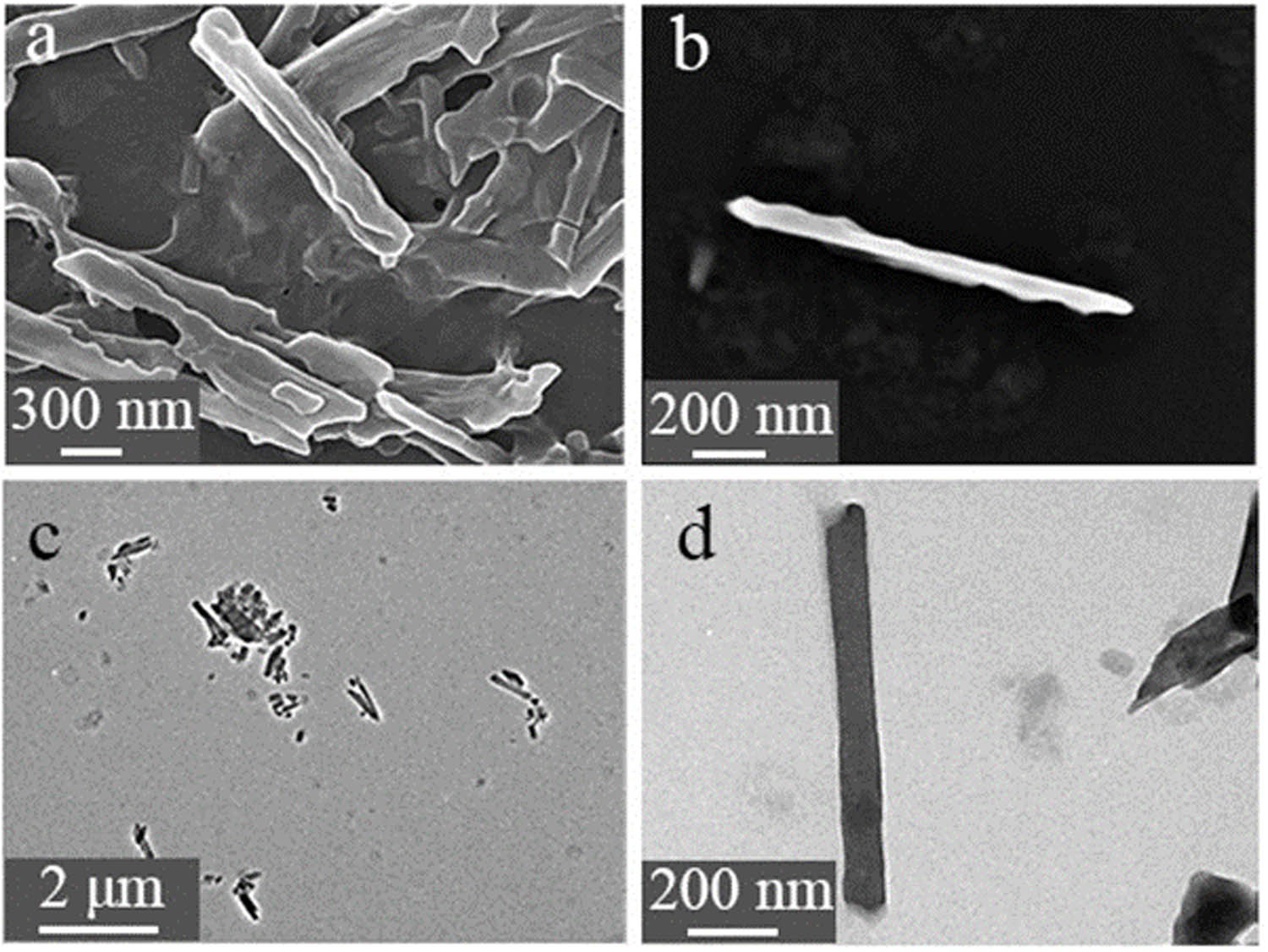
Figure 1 and FigureA1 show the morphology and EDS of TE@Zn-MOFs obtained by SEM and TEM. Compared with the unmodified nanorods (Figure A2) [37], the surface of TE@Zn-MOFs became rough and the diameter increased by about 200 nm. In addition, some nanorods have a shortened aspect ratio after modification, forming a similar spherical substance. Figure A1 shows that TE@Zn-MOFs contain C, O, S, N, Zn and Fe, proving that PEDOT is successfully introduced into TE@Zn-MOFs.
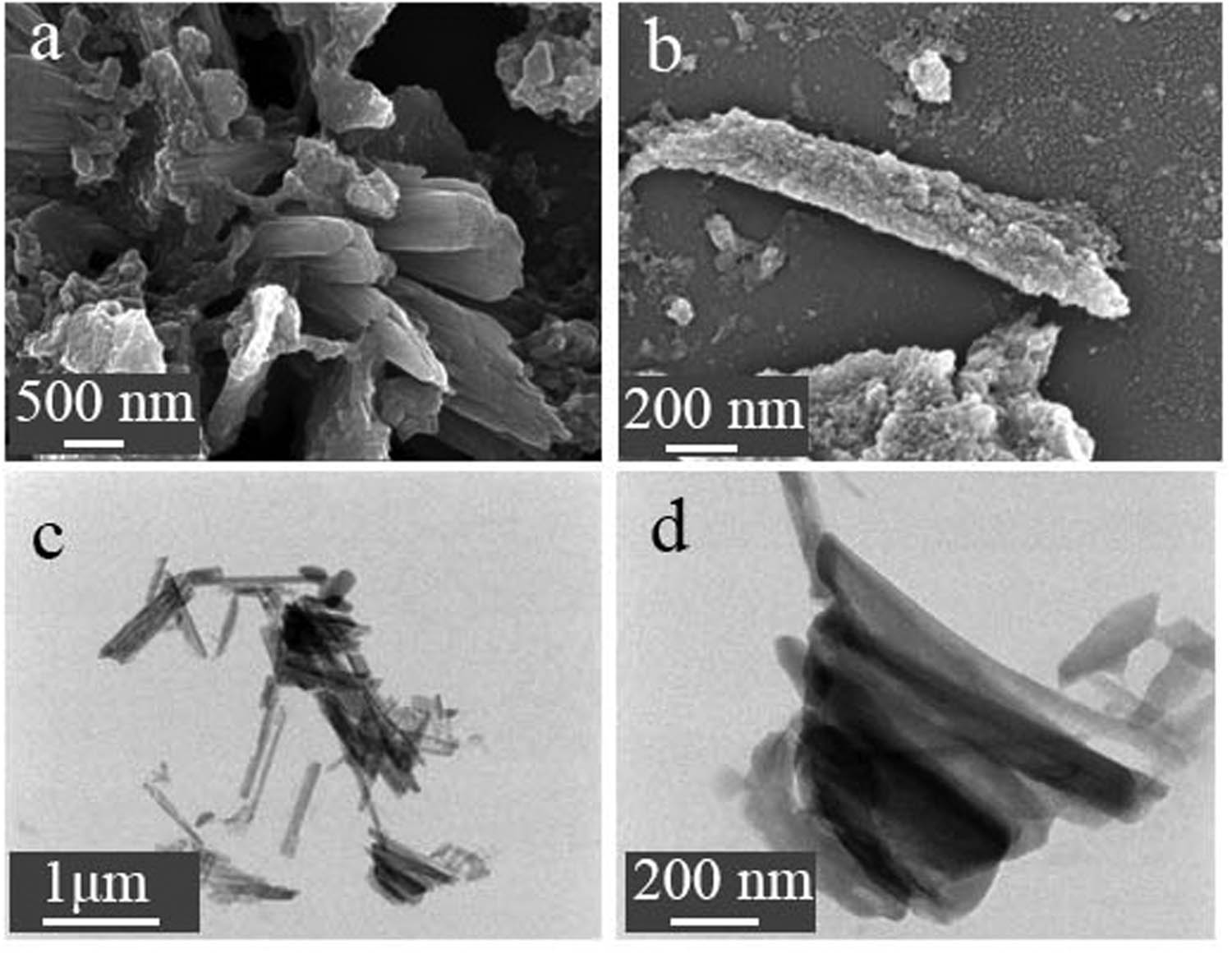
(a, b) SEM and (c, d) TEM images of TE@Zn-MOFs.
Figure 2 shows the FTIR, XRD and XPS spectra of TE@Zn-MOFs. Compared to Zn-MOFs nanorods without PEDOT modification, TE@Zn-MOFs show new characteristic peaks at 1,315, 1,067, 838 and 701 cm−1. The characteristic peak was observed at 1,315 cm−1, corresponding to C–C. The characteristic peak was observed at 1,067 cm−1, corresponding to C–O–C. Peaks were also observed at 838 and 701 cm−1, attributing to stretching vibrations of the C–S–C bond in thiophene ring (Figure 2a) [38]. Figure 2b also shows that the crystal structure of TE@Zn MOFs has not changed significantly. Except that the characteristic peaks of PEDOT in the diffraction pattern located at 13.5° and 25.9°, corresponding to (200) peak and (020) peak, respectively. The (020) characteristic diffraction peak is the stacking distance of the planar rings between molecular chains of PEDOT. In addition, the XPS results of TE@Zn-MOFs prove the existence of C, O, Zn and S (Figure 2c). There are four peaks of C–C/C–H, C═ O, C–O and C–S in the C 1s spectrum of nanorods, which are located at 284.8, 289.13, 286.2 and 287.1 eV, respectively, indicating that C maintains the chemical state of PHBA and PEODT, and no new structural form appears. There are four peaks of Zn–O 2p1/2, Zn 2p3/2, Zn–O and Zn–S in the XPS spectrum of Zn 2p, which are located at 1,045.63, 1,022.53, 1,021.7 and 1,022.3 eV, respectively. Therefore, Zn2+ exists in nanorods and there is a coordination reaction between Zn and S in PEDOT. There are two absorption peaks of S 2p and SO4 2– in the S 2p spectrum of nanorods, which are located at 164.2 and 168.5 eV, respectively. This also shows that Zn has a coordination reaction with S in PEDOT. Based on the morphology data of the nanorods, the synthesis process of TE@Zn-MOFs did not change the structure of the organic molecules. Zn binds to the organic molecules through coordination, forming a MOF material with Zn as the connecting point. Therefore, the chemical structure of TE@Zn-MOFs is shown in Figure 2h.
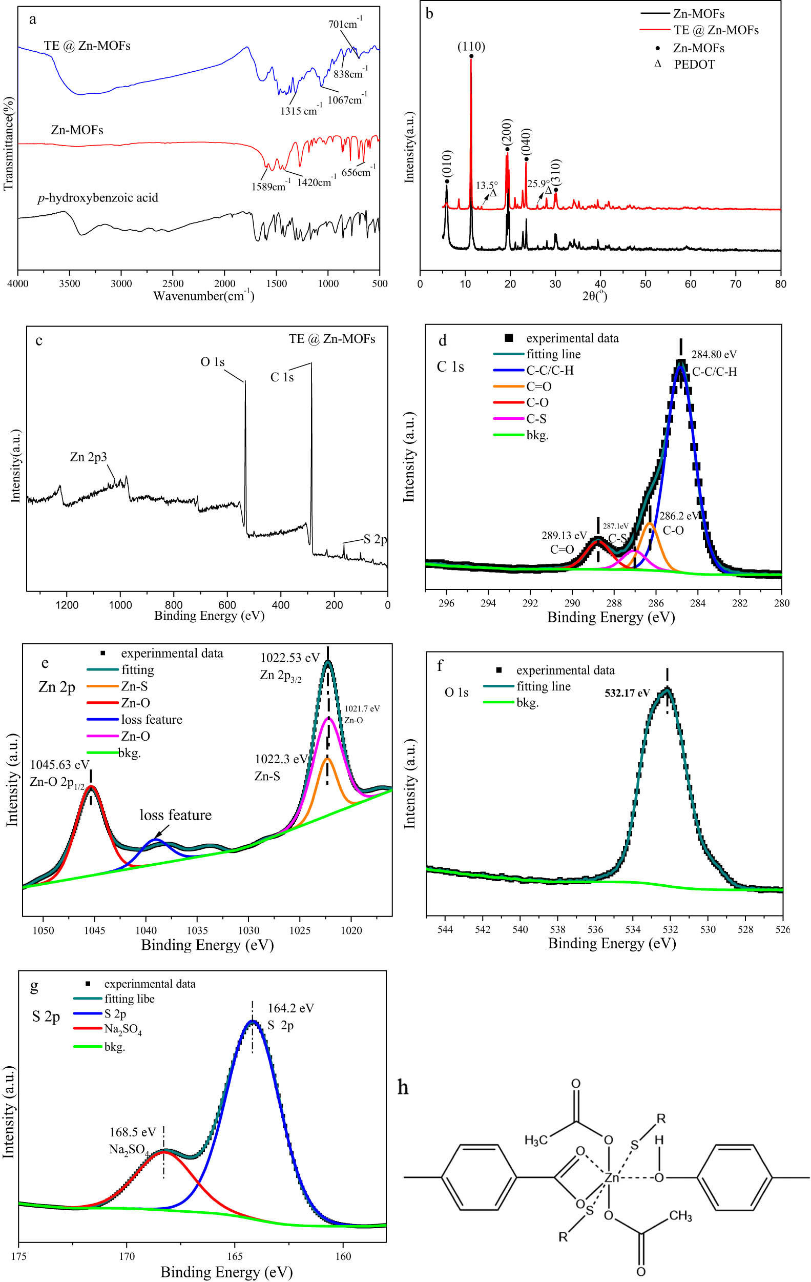
Structural characterization of TE@Zn-MOFs: (a) FTIR spectra, (b) XRD pattern, (c) XPS survey, (d) C 1s, (e) Zn 2p, (f) O 1 s, (g) S 2p and (h) possible structural forms.
Figure A3 shows the adsorption–desorption curve and pore size distribution of TE@Zn-MOFs. Specific surface area of TE@Zn-MOFs was obtained by BJH calculation. According to the physical adsorption isotherms classification method recommended by IPUAC in 2015, the curve of TE@Zn-MOFs belongs to the type II adsorption isotherm. Generally, gas adsorption isotherms generated by nonporous or macroporous materials exhibit reversible type II isotherms, and their lines reflect unrestricted monolayer–multilayer adsorption. The specific surface area of TE@Zn-MOFs (35.3823 m2·g–1) is larger than that of other linear materials [39,40]. The larger specific surface area of the nanorods means that the possibility of agglomeration and deactivation of the nanorods is reduced at a relatively high addition amount, which is beneficial to achieve a higher addition amount in the polymer coating matrix to obtain better functional properties [41,42].
3.2 Basic physical properties of TE@Zn-MOFs/Epoxy coatings
Table A1 shows the density of TE@Zn-MOFs/Epoxy coatings. With the increase of TE@Zn-MOFs, the coating density decreases. Compared to pure matrix coatings, the density of the coating with 10 wt% fillers decreased from 1.230 to 1.157, about 6%.
Table A2 shows the basic physical properties of TE@Zn-MOFs/Epoxy coatings. When the addition amount of TE@Zn-MOFs is 10 wt%, the adhesion of the coating decreases from level 0 to level 1, the hardness decreases from 50.60 H to 36.07 H, and the viscosity increases from 58.80 to 86.40 Pa·s. There is no difference in the surface drying time of different samples. Therefore, this also shows that the fillers change the inherent properties of the matrix.
Table A3 shows the mechanical properties of TE@Zn-MOFs/Epoxy coatings, including tensile strength, tensile shear strength and impact strength. In general, the addition of TE@Zn-MOFs inevitably leads to a decrease in the mechanical properties of the coating. Specifically, compared with the filler-free coating substrate, the tensile strength of the coating with 10 wt% TE@Zn-MOFs decreased from 8.52 to 3.31 MPa, about 61%, the tensile shear strength decreased from 20.43 to 12.53 MPa, about 39% and the impact strength decreased from 20.28 to 6.55 MPa, about 67%. Figure A4 shows the tensile section of TE@Zn-MOFs/Epoxy coatings. The tensile section of the filler-free coating is smooth and has only a few shear bands. As the amount of filler increases, the roughness and holes of the tensile section gradually increase. In addition, the surface of the tensile section is not continuous, and different degrees of cracks appear. This also confirms that the greater the amount of TE@Zn-MOFs, the worse the mechanical properties of the coatings. Therefore, the addition of functional flame-retardant fillers leads to deterioration of the mechanical properties of the coating. This also proves the advantages of the flame-retardant coating, which effectively improves the flame retardancy of the protected material without affecting the mechanical properties and basic physical properties of the protected material.
3.3 Flame retardation of TE@Zn-MOFs/Epoxy coatings
Table 2 shows the vertical combustion classification and LOI of TE@Zn-MOFs/Epoxy coatings. The coating without TE@Zn-MOFs cannot be classified under vertical combustion conditions and the LOI is only 18.2%. When the additional amount of TE@Zn-MOFs was 10 wt%, the coating achieved V-0 under vertical combustion conditions and LOI increased from 18.2% to 29.0%, about 60%. This shows that the filler effectively improves the flame retardancy of the coating.
Flame retardation of TE@Zn-MOFs/Epoxy coatings
| Sample | UL-94 | LOI (%) | ||||
|---|---|---|---|---|---|---|
| t1 (s) | t2 (s) | Dripping | Ignite the cotton | Rating | ||
| TE@Zn-MOFs/Epoxy0 | — | — | Yes | Yes | — | 18.2 |
| TE@Zn-MOFs/Epoxy1 | — | — | Yes | Yes | 23.3 | |
| TE@Zn-MOFs/Epoxy2 | 3 | 20 | Yes | Yes | V-2 | 24.5 |
| TE@Zn-MOFs/Epoxy3 | 3 | 15 | Yes | No | V-1 | 26.8 |
| TE@Zn-MOFs/Epoxy4 | 5 | 3 | No | No | V-0 | 29.0 |
Figure A5 shows the combustion of TE@Zn-MOFs/Epoxy0 and TE@Zn-MOFs/Epoxy4 at an oxygen index of 25%. TE@Zn-MOFs/Epoxy0 burns rapidly after contact with the flame and has obvious dripping phenomenon. In addition, the sample was essentially burned after 160 s of combustion. When the additional amount of TE@Zn-MOFs is 10 wt%, the sample is exposed to 40 s under the flame to have a slight ignition phenomenon, and the flame is quickly extinguished after the sample is removed from the fire source, which also confirms the effectiveness of TE@Zn-MOFs to improve the flame retardancy of the coating.
Figure A6 is an electronic image of the sample after the oxygen index test. Compared to unmodified samples, samples with TE@Zn-MOFs maintained the integrity of the shape. In addition, the higher the amount of TE@Zn-MOFs added, the better the integrity of the sample. This shows that the addition of fillers can catalyze the formation of residual char and has a positive effect on the improvement of the structural density of residual char. The dense residual char is beneficial in inhibiting the heat release and gas release of the sample during combustion [43,44].
3.4 Fire behavior on TE@Zn-MOFs/Epoxy coatings
The release of TE@Zn-MOFs/Epoxy coatings was examined by using a cone calorimeter. Figure 3 shows the heat release rate (HRR), total heat release rate (THR) and mass loss curves of TE@Zn-MOFs/Epoxy coatings. Table A4 provides quantitative data for cone calorimeter test samples. The HRR and THR curves of samples with TE@Zn-MOFs were lower than those without TE@Zn-MOFs throughout the combustion process. When the content of TE@Zn-MOFs is 4, 6, 8 wt%, the difference between the HRR curve of the coating is not obvious, and the peak time is delayed. The incorporation of PEDOT into Zn-MOFs resulted in minimal differences among zinc (transition element) content of these three sets of samples. Zinc plays a catalytic role in char formation during the combustion process of the coating sample. The dense carbon layer is beneficial to inhibit the release of heat and smoke. Therefore, when the difference in zinc content is not obvious, the difference in HRR curve is not obvious.
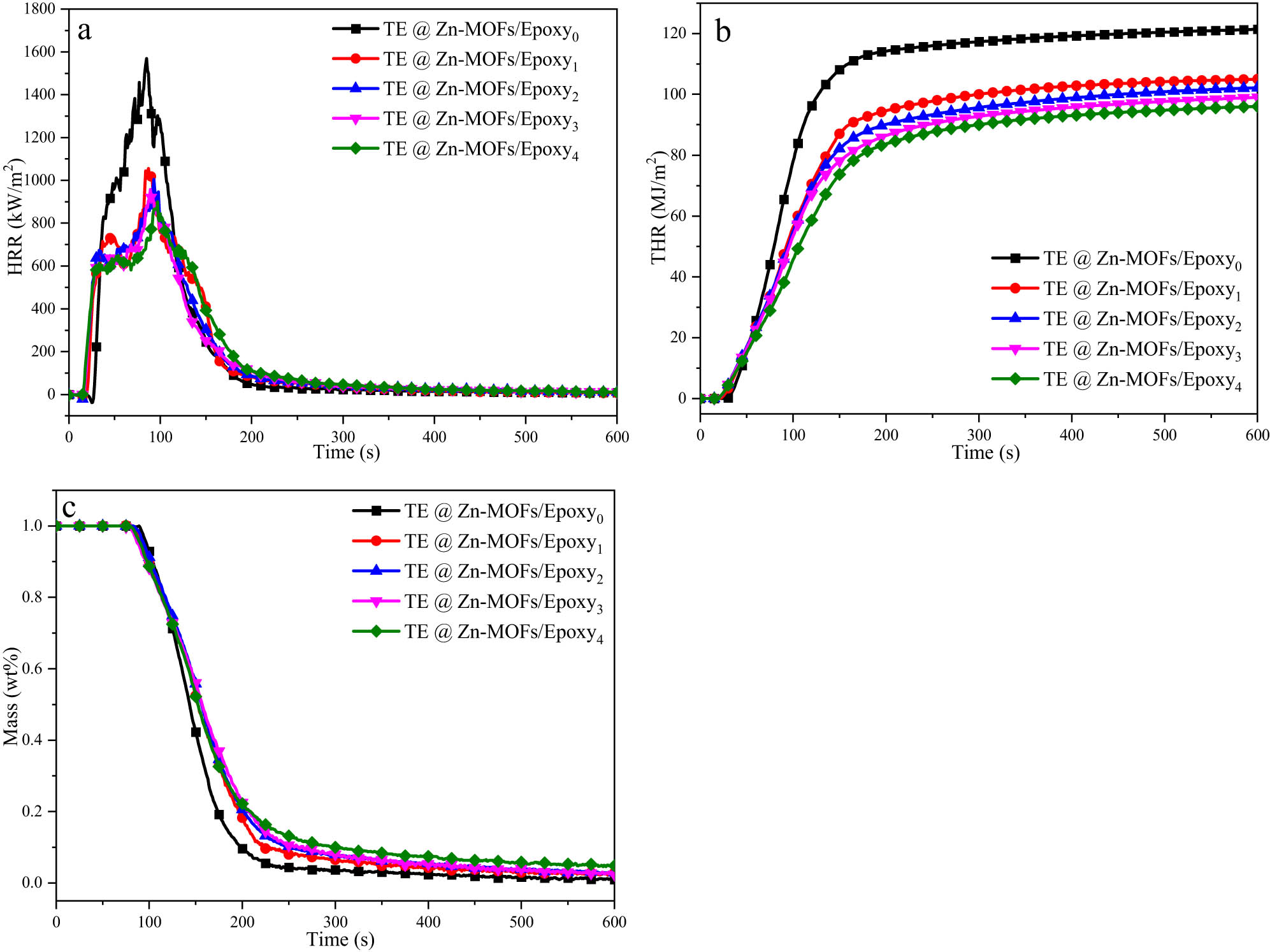
(a) HRR, (b) THR and (c) mass loss curves of TE@Zn-MOFs/Epoxy coatings.
In addition, with the increase of TE@Zn-MOFs, the amount of residual char of the sample also gradually increased. flame growth rate (FGR) is the ratio of pHRR to tpHRR. The smaller the FGR, the better the safety of the material in the event of fire, which can provide a longer window period for fire [45]. Compared to the unmodified coating, when the additional amount of TE@Zn-MOFs was 10 wt%, the FGR of the coating decreased from 18.72 to 9.29, about 50%. Therefore, the addition of TE@Zn-MOFs effectively increased the amount of residual char and inhibited the heat release of the coating during combustion.
Polymer-based materials often release smoke during combustion. These fumes can cause a significant drop in vision and are often toxic. Therefore, another necessary condition to determine whether the flame-retardant filler is effective in improving the flame retardancy of polymer-based materials is the inhibitory effect on smoke release during combustion. Figure 4 shows the smoke release rate (SPR), total smoke release (TSP), CO release rate (COP) and CO2 release rate (CO2P) curves of TE@Zn-MOFs/Epoxy coatings. The smoke release curve of the coatings is consistent with the shape and trend of the heat release curve of the coatings, i.e., TE@Zn-MOFs efficiently inhibits the smoke release of the coatings. When the content of TE@Zn-MOFs is 4, 6, 8 wt%, the difference between the SPR and TSP curves of the coating is not obvious, and the peak time is delayed. The reason for this is consistent with the reason why the difference in HRR curve is not obvious. When the content of TE@Zn MOFs is 10 wt%, the curve of the coating shows significant changes and the peak reaches the lowest. The specific values of TSP, PSPR, PCO2P and PCOP in Table A4 also illustrate this point. Therefore, TE@Zn-MOFs efficiently inhibits the release of coatings, providing favorable support for fire rescue and personnel escape.
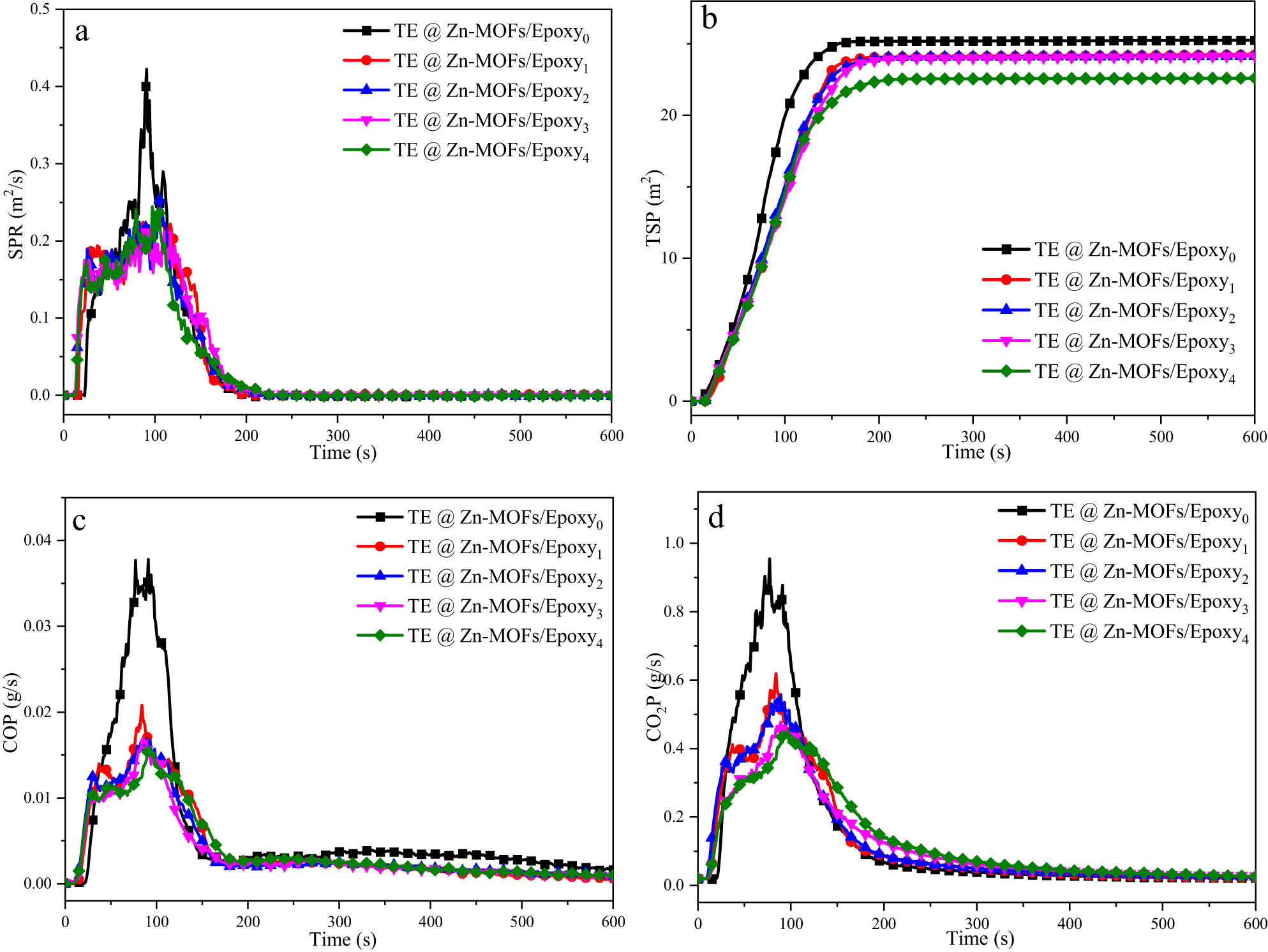
(a) SPR, (b) TSP and (c, d) CO and CO2 release rates curves for TE@Zn-MOFs/Epoxy coatings.
3.5 Thermoelectric properties of TE@Zn-MOFs/Epoxy coatings
Figure 5 shows the electrical conductivity of TE@Zn-MOFs/Epoxy coatings. Compared to pure matrix coatings, the density of the coating with 10 wt% TE@Zn-MOFs increased from 0.89 × 10⁻¹⁴ to 1.06 × 10⁻³ S·cm−1. As a MOF, TE@Zn-MOFs have a large surface area and size effect. Therefore, TE@Zn-MOFs content increases, resulting in an increase in carrier concentration. When the filler content increases to 10 wt%, the conductivity of TE@Zn-MOFs/Epoxy coatings changes by order of magnitude.
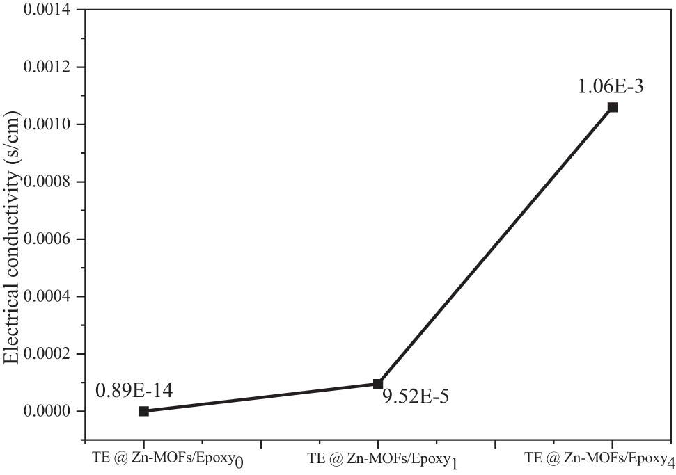
Electrical conductivity of Epoxy coatings as a function of TE@Zn-MOFs content.
Figure A7 is a schematic diagram for detecting the thermoelectric properties of TE@Zn-MOFs/Epoxy coatings. According to ZT = S 2 Tσ/κ (ZT is the thermoelectric figure of merit, S is the Seebeck coefficient, T is the absolute temperature, σ is the electrical conductivity and κ is the thermal conductivity), the thermoelectric efficiency of the TE coatings is proportional to its electrical conductivity. When one side of the coating is heated, the carriers on the high temperature side will migrate along the temperature gradient to the low temperature side, resulting in a potential difference between the high and low temperature ends. When TE@Zn-MOFs content increases, the carrier concentration migrated due to heating also increases, so that the output voltage of TE@Zn-MOFs/Epoxy coatings rises faster when heated, and the maximum output voltage can be achieved higher.
The output current curves of TE@Zn-MOFs/Epoxy coatings at different heating temperatures were studied by paperless recorder and matching voltage transmitter. Figure 6a shows the output current curve of the coating heated at 50°C. The sample without TE@Zn-MOFs had no current output during the heating process of 60 s, while the coating with TE@Zn-MOFs had current output. In addition, the maximum current output values of coatings with 4 and 6 wt% addition are 0.32 and 0.2 mA, respectively, which remain in the same order of magnitude. The maximum current output values of samples with 8 and 10 wt% addition are 30 and 90 mA, respectively. From the perspective of the current appearance time, the current appearance time of the samples with 4 and 10 wt% TE@Zn-MOFs is about 20 s. Similarly, the samples without TE@Zn-MOFs had no current output during the heating process at 100°C, 150°C and 200°C (Figure 6b–d), while the sample with 10 wt% TE@Zn-MOFs had the largest output current (∼80 mA) and the earliest time of current occurrence (∼10 s). Compared to traditional infrared and other early warning devices that require about 100 s of detection time, the fire warning performance of the coating system is significantly improved.
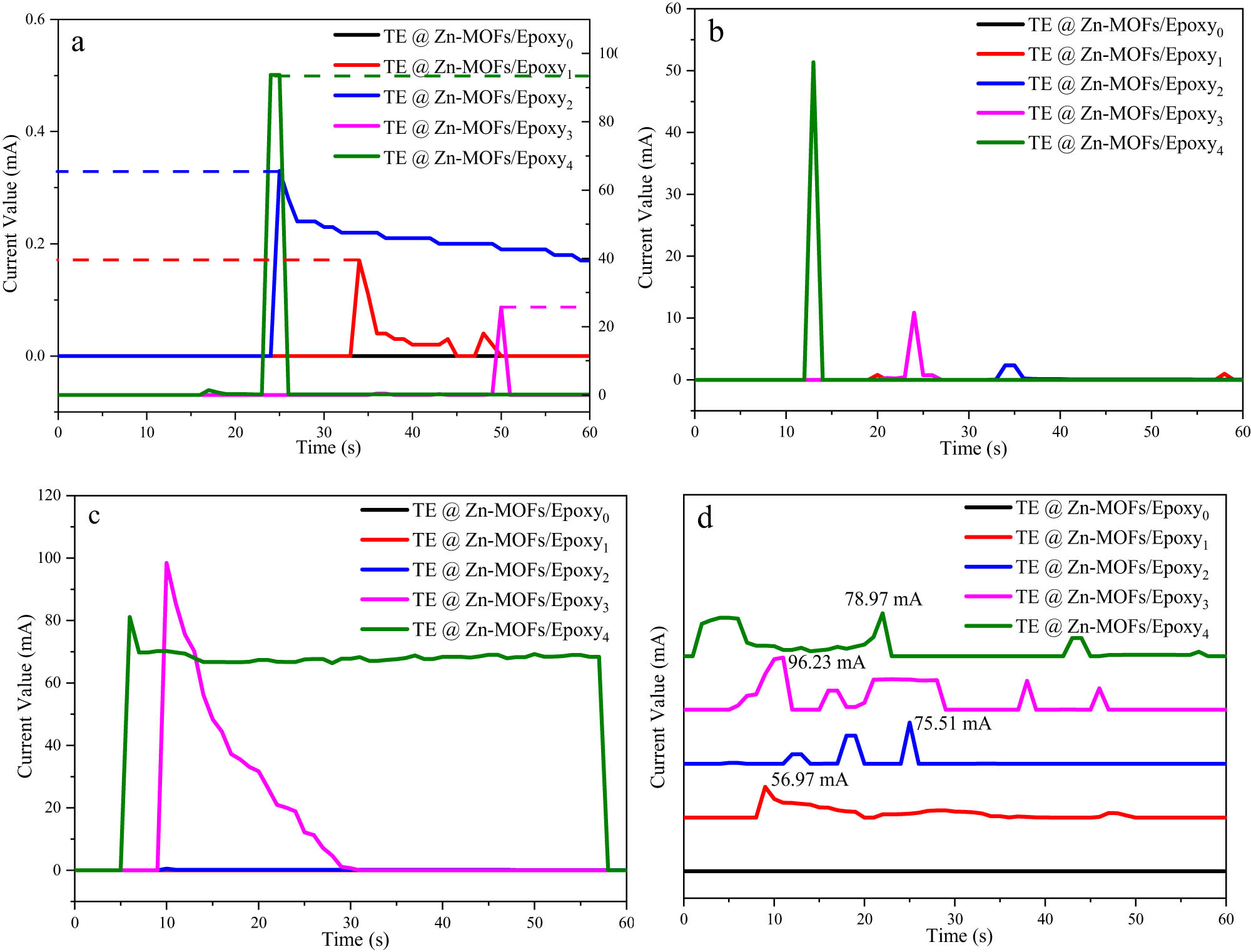
The output current curves of TE@Zn-MOFs/Epoxy coatings heated at: (a) 50℃, (b) 100℃, (c) 150℃ and (d) 200℃.
Figure A8 shows the XPS spectrum of TE@Zn-MOFs/Epoxy coatings before and after the fire alarm test. The spectra of coatings without TE@Zn-MOFs were basically consistent before and after the test, and no new chemical bonds appeared. The coatings with 10 wt% TE@Zn-MOFs showed a π–π* satellite peak after the fire warning test, which indicated that PEDOT formed a π–π conjugate effect during the heating process of the coating, which caused the thermoelectric effect under the environmental conditions of the temperature difference of the coating [46]. This is also consistent with the previously reported thermoelectric mechanism of PEDOT.
3.6 Mechanisms of flame retardation and smoke suppression
Figure 7 shows digital photographs of the residual char of the coatings after the cone calorimeter test. The residual carbon of the unmodified coating is in the powder state. With the increase of TE@Zn-MOFs, the integrity and continuity of residual char are increasing. In addition, the bottom tin paper of the unmodified coating was burned, while the degree of damage to the bottom tin paper of the coating with TE@Zn-MOFs was inversely proportional to the amount of TE@Zn-MOFs. The fourth line in Figure 7 shows SEM of residual char from TE@Zn-MOFs/Epoxy coatings. Compared with the discontinuous state of residual tchar in unmodified coatings, the integrity of residual char in modified coatings continues to increase and shows two different color levels, indicating that the addition of TE@Zn-MOFs has a positive effect on residual char formation and residual char continuity.

Digital photographs (first–third rows) and SEM images (fourth row) of residual char from (a) TE@Zn-MOFs/Epoxy0, (b) TE@Zn-MOFs/Epoxy1, (c) TE@Zn-MOFs/Epoxy2, (d) TE@Zn-MOFs/Epoxy3 and (e) TE@Zn-MOFs/Epoxy4.
To further verify whether the filler has an effect on the formation and densification of residual char, the residual char of the sample was detected by Raman spectroscopy. The two peaks in Figure A9 correspond to graphite carbon (1,580 cm−1) and amorphous carbon (1,350 cm−1), respectively [47]. The ratio of amorphous carbon to graphite carbon is inversely proportional to the compactness of residual char [47]. The dense carbon layer helps to isolate oxygen and inhibit the release of flue gas and heat [43,44]. Therefore, TE@Zn-MOFs catalyzes the formation and densification of residual char, which plays a positive role in improving the flame retardancy of epoxy-based coatings.
Figure A10 shows the TG-IR of TE@Zn-MOFs/Epoxy0 and TE@Zn-MOFs/Epoxy4. Compared to TE@Zn-MOFs/Epoxy0, the total gas release, carbonyl compounds, hydrocarbons and CO2 of TE@Zn-MOFs/Epoxy4 decreased significantly. In addition, the amount of combustible gas (ethers) and non-combustible gas (CO) did not change much. This shows that TE@Zn-MOFs have no flame-retardant effect in the gas phase field, but only effectively catalyzes the formation and densification of residual char, resulting in a decrease in the gas release of the coatings.
In summary, the mechanism of TE@Zn-MOFs to improve the flame retardancy of epoxy-based coatings and give the coating fire warning performance is divided into the following three points. First, the introduction of organic frameworks has greatly improved the dispersion of nano-flame retardants in the resin, ensuring that the nano-flame retardants will not lose the ability to improve the flame retardancy of the coating due to agglomeration failure at a relatively high addition amount. Second, zinc (transition metal element) contained in TE@Zn-MOFs effectively catalyzes the formation and densification of residual char in the coating during combustion, which effectively isolates oxygen and heat exchange with the outside world, so that the coating obtains the ideal flame retardant and smoke suppression effect. Third, through a simple solvothermal method, the thermoelectric organic PEDOT is introduced into the nano-flame retardant, which gives the coating the ability to perceive temperature changes and output a certain current. The output of this part of the value can be used as a signal source for fire warning, so as to effectively perceive the emergence of fire without power supply, and win valuable time for dealing with fire. The specific mechanism diagram is shown in Figure 8.
Possible flame retardation and fire warning mechanisms for TE@Zn-MOFs in epoxy coatings.
4 Conclusions
A MOF (TE@Zn-MOFs) with both flame retardancy and thermoelectricity was synthesized by a simple and efficient solvothermal method. When the additional amount of TE@Zn-MOFs is 10 wt%, the LOI of the epoxy-based coating reaches 29.0%, and the V-0 level flame retardant is achieved in the vertical combustion test. In addition, the total heat release and total gas release of the coating decreased by 21% and 11%, respectively. In addition, TE@Zn-MOFs endow the coating with the ability to sense temperature changes and output a certain current. The induction time is about 20 s and the output current value can reach nearly 100 mA. Therefore, the addition of TE@Zn-MOFs effectively improves the flame retardancy and smoke suppression of the coating and gives the coating a potential performance for fire warning, which provides a way for the development of multifunctional coatings with a simple synthesis process.
-
Funding information: Authors state no funding involved.
-
Author contributions: Guorong Wang: writing – original draft, conceptualization, methodology, writing – review & editing; Zhiyuan Mei: supervision; Yu Li: validation; Zhaoyi Sun: methodology; Guotao Chen: visualization.
-
Conflict of interest: Authors state no conflict of interest.
-
Data availability statement: All data generated or analyzed during this study are included in this published article (and its supplementary information files).
Appendix
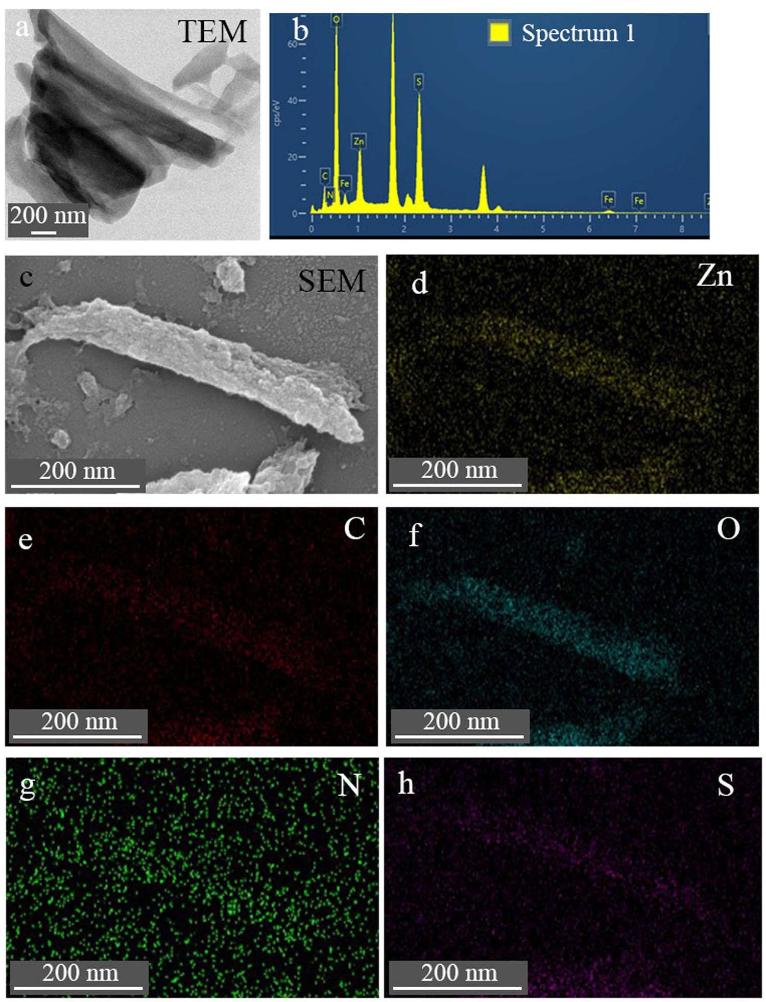
(a) TEM, (b) EDS under TEM, (c) SEM and (d–h) elemental mapping under SEM of TE@Zn-MOFs.
(a, b) SEM images and (c, d) TEM images of Zn-MOFs nanorods.
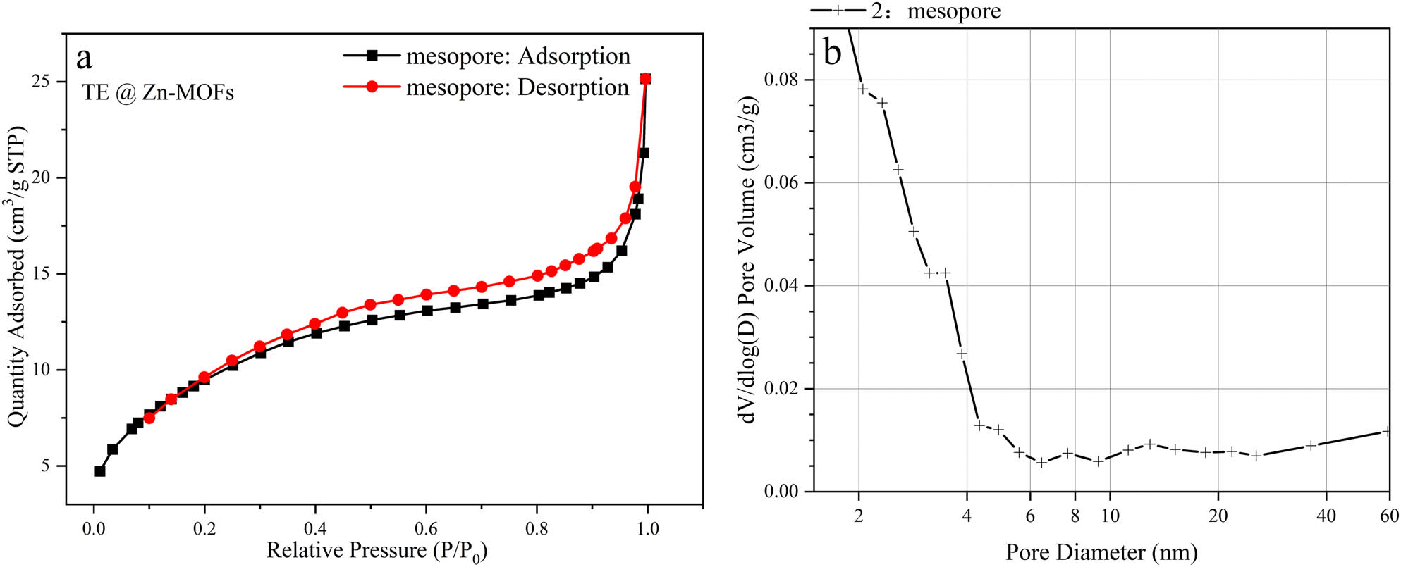
(a) Adsorption–desorption isotherms and (b) BJH desorption dV/dlog(D) pore volume of TE@Zn-MOFs.
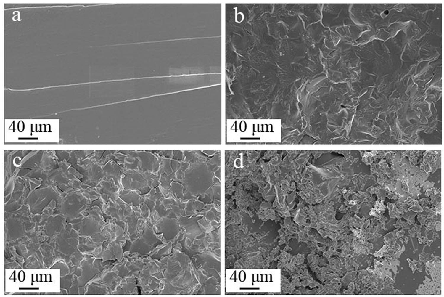
SEM images of tensile fracture surfaces: (a) TE@Zn-MOFs/Epoxy0, (b) TE@Zn-MOFs/Epoxy1, (c) TE@Zn-MOFs/Epoxy3 and (d) TE@Zn-MOFs/Epoxy4.
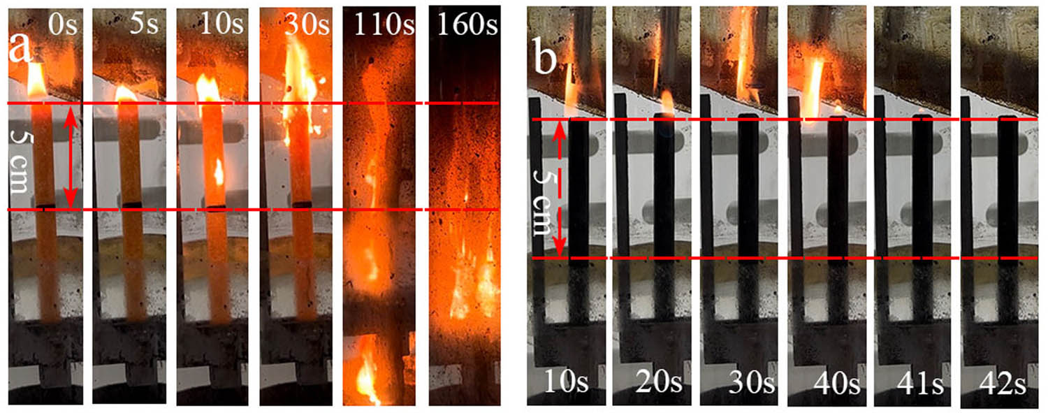
Digital photographs of (a) TE@Zn-MOFs/Epoxy0 and (b) TE@Zn-MOFs/Epoxy4 during combustion at LOI of 25.0%.
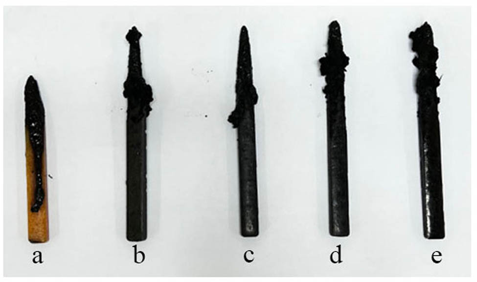
Digital photographs of (a) TE@Zn-MOFs/Epoxy0, (b) TE@Zn-MOFs/Epoxy1, (c) TE@Zn-MOFs/Epoxy2, (d) TE@Zn-MOFs/Epoxy3 and (e) TE@Zn-MOFs/Epoxy4 after combustion at LOI.
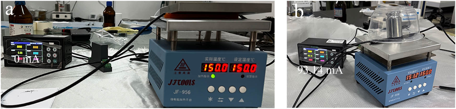
Digital photographs of (a) TE@Zn-MOFs/Epoxy0 and (b) TE@Zn-MOFs/Epoxy4 heated at 150°C.
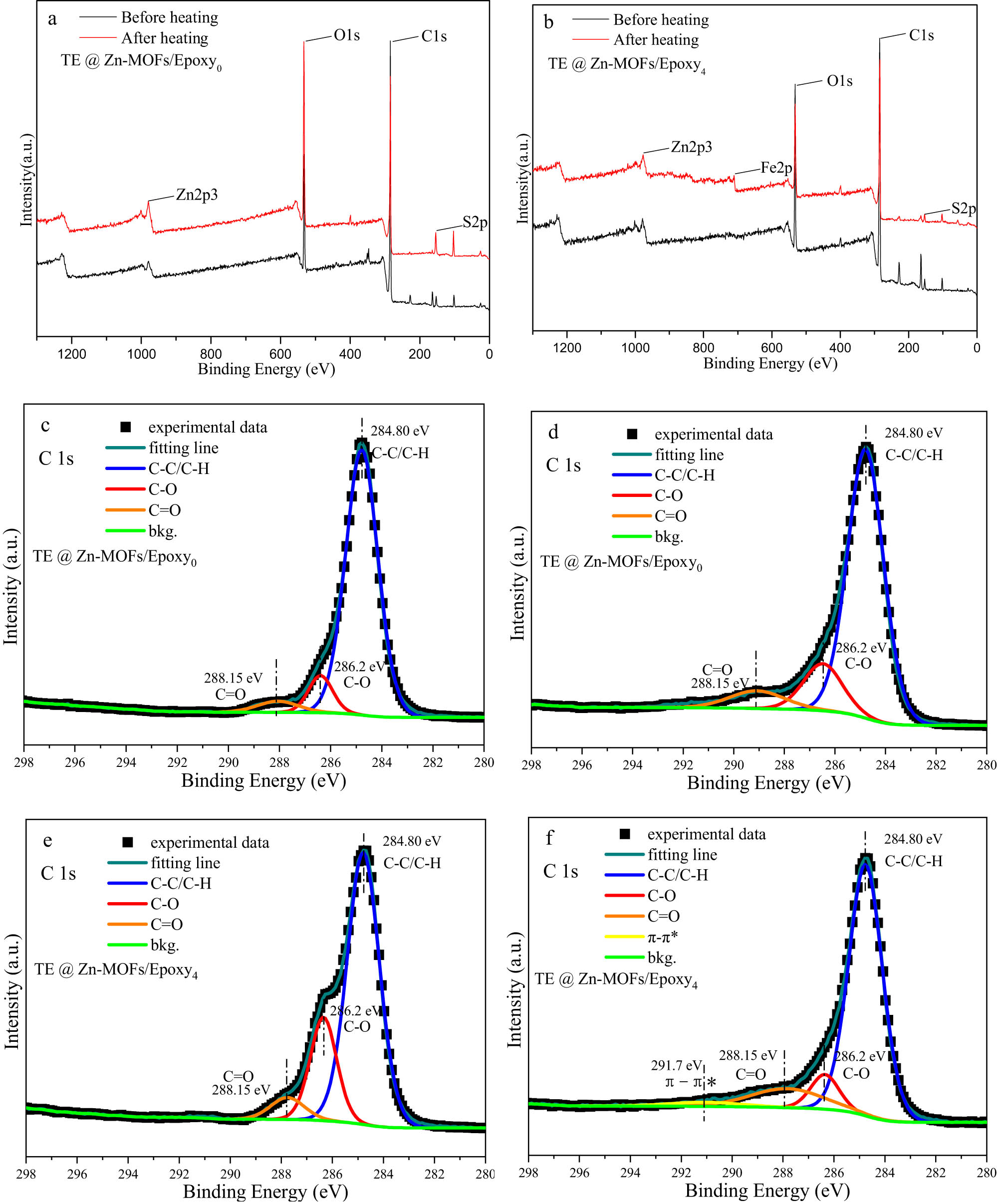
XPS spectra of TE@Zn-MOFs/Epoxy0 (a) and TE@Zn-MOFs/Epoxy4 (b) before and after the fire test; C1s spectra of TE@Zn-MOFs/Epoxy0 before (c) and after (d) fire test; C1s spectra of TE@Zn-MOFs/Epoxy4 before (e) and after (f) fire test.
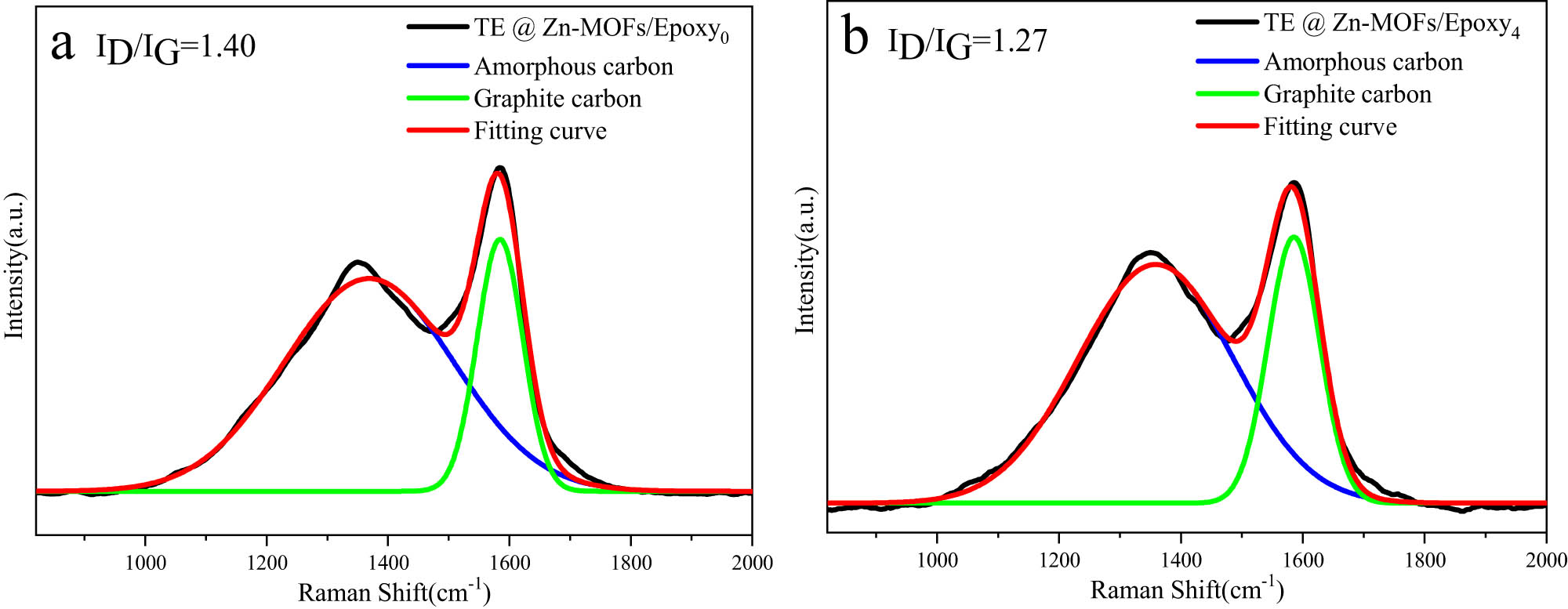
Raman spectra of the residues from (a) TE@Zn-MOFs/Epoxy0 and (b) TE@Zn-MOFs/Epoxy4.
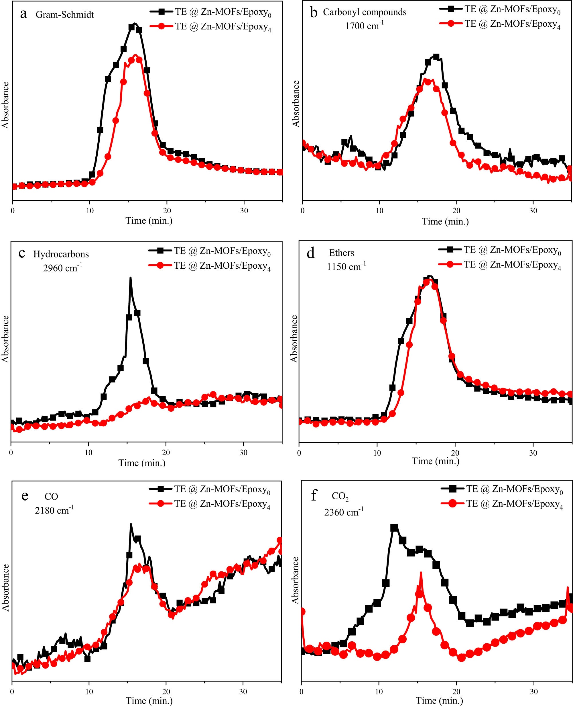
(a) Gram-Schmidt, (b) carbonyl compounds, (c) hydrocarbons, (d) ethers, (e) CO and (f) CO2 of TG-IR of TE@Zn-MOFs/Epoxy0 and TE@Zn-MOFs/Epoxy4.
Density and porosity of TE@Zn-MOFs/Epoxy coatings
| Sample | Theoretical density (g·cm–3) | Measuring density (g·cm–3) | Porosity (%) |
|---|---|---|---|
| TE@Zn-MOFs/Epoxy0 | 1.230 | 1.226 ± 0.003 | 0.325 |
| TE@Zn-MOFs/Epoxy1 | 1.201 | 1.157 ± 0.004 | 3.648 |
| TE@Zn-MOFs/Epoxy2 | 1.186 | 1.127 ± 0.004 | 4.991 |
| TE@Zn-MOFs/Epoxy3 | 1.172 | 1.101 ± 0.007 | 6.026 |
| TE@Zn-MOFs/Epoxy4 | 1.157 | 1.079 ± 0.006 | 6.742 |
Basic physical properties of TE@Zn-MOFs/Epoxy coatings
| Sample | Adhesion (level) | Hardness (H) | Viscosity (Pa s) | Surface drying time (h) |
|---|---|---|---|---|
| TE@Zn-MOFs/Epoxy0 | 0 | 50.60 ± 0.51 | 58.80 ± 0.15 | 1 h 44 min |
| TE@Zn-MOFs/Epoxy1 | 0 | 42.00 ± 0.20 | 66.40 ± 0.30 | 1 h 20 min |
| TE@Zn-MOFs/Epoxy2 | 0 | 40.23 ± 0.60 | 72.40 ± 0.15 | 1 h 35 min |
| TE@Zn-MOFs/Epoxy3 | 0 | 38.83 ± 0.31 | 81.60 ± 0.21 | 1 h 54 min |
| TE@Zn-MOFs/Epoxy4 | 1 | 36.07 ± 0.25 | 86.40 ± 0.40 | 1 h 51 min |
Mechanical properties of TE@Zn-MOFs/Epoxy coatings
| Sample | Tensile strength (MPa) | Shear bond strength (MPa) | Impact strength (kJ·m–2) |
|---|---|---|---|
| TE@Zn-MOFs/Epoxy0 | 8.52 ± 0.20 | 20.43 ± 0.08 | 20.28 ± 0.15 |
| TE@Zn-MOFs/Epoxy1 | 4.36 ± 0.07 | 18.45 ± 0.09 | 13.16 ± 0.18 |
| TE@Zn-MOFs/Epoxy2 | 3.87 ± 0.04 | 16.23 ± 0.41 | 10.59 ± 0.14 |
| TE@Zn-MOFs/Epoxy3 | 3.70 ± 0.04 | 14.46 ± 0.06 | 9.73 ± 0.19 |
| TE@Zn-MOFs/Epoxy4 | 3.31 ± 0.05 | 12.53 ± 0.18 | 6.55 ± 0.09 |
Cone calorimeter data of TE@Zn-MOFs/Epoxy coatings
| Sample | TE@Zn-MOFs/Epoxy0 | TE@Zn-MOFs/Epoxy1 | TE@Zn-MOFs/Epoxy2 | TE@Zn-MOFs/Epoxy3 | TE@Zn-MOFs/Epoxy4 |
|---|---|---|---|---|---|
| p HRR (kW·m–2) | 1,572.57 | 1,058.79 | 1,006.53 | 958.71 | 901.43 |
| THR (MJ·m–2) | 121.39 | 104.99 | 102.16 | 99.00 | 96.01 |
| Residue (wt%) | 0.74 | 2.08 | 1.85 | 2.27 | 4.51 |
| TSP (m2) | 25.26 | 24.24 | 24.14 | 24.15 | 22.60 |
| t pHRR (s) | 84 | 87 | 93 | 88 | 97 |
| PSPR (m2·s–1) | 0.42 | 0.24 | 0.25 | 0.21 | 0.24 |
| PCO2P (g·s–1) | 0.95 | 0.62 | 0.56 | 0.48 | 0.45 |
| PCOP (g·s–1) | 0.04 | 0.02 | 0.02 | 0.02 | 0.02 |
| FGR | 18.72 | 12.17 | 10.82 | 10.89 | 9.29 |
References
(1) Riddle MS, Sherman SS, Kilbane EM, Putnam SD. A multivariate analysis of factors associated with differential disease and nonbattle injury and morbidity aboard ships of the U.S. Naval 5th Fleet during peacetime deployment. Milit Med. 2004;169(10):787–94. 10.7205/MILMED.169.10.787.Search in Google Scholar
(2) King MJ, Betts LS, Sonenshine DE. House dust mites in naval ships, military barracks, and homes in the Hampton Roads area of Virginia. Milit Med. 1989;154(9):467–73. 10.1093/milmed/154.9.467.Search in Google Scholar
(3) Christiansen M, Fagerholt K, Nygreen B, Ronen D. Chapter 4. Maritime transportation. Handb Oper Res Manag Sci. 2007;14:189–284. 10.1016/S0927-0507(06)14004-9.Search in Google Scholar
(4) Wilson JR. Ship and aircraft fire fighting on combatant vessels. Nav Eng J. 1963;75(4):745–62. 10.1111/j.1559-3584.1963.tb04928.x.Search in Google Scholar
(5) Sorathia U, Ness J, Blum M. Fire safety of composites in the US Navy. Compos Part A Appl Sci Manuf. 1999;30(5):707–13. 10.1016/S1359-835X(98)00112-2.Search in Google Scholar
(6) Dong ZJ, Chen GT, Mei ZY, Zhang Y. Research on the thermal insulation performance of marine composite. China Plast Ind. 2021;49(12):100–6. 10.3969/j.issn.1005-5770.2021.12.020.Search in Google Scholar
(7) Pohler CH, Mcvoy JL, Carhart HW, Leonard JT, Pride TS. Fire safety of naval ships – an open challenge. Nav Eng J. 1978;90(2):21–30. 10.1111/j.1559-3584.1978.tb04271.x.Search in Google Scholar
(8) Gubbi J, Marusic S, Palaniswami M. Smoke detection in video using wavelets and support vector machines. Fire Saf J. 2009;44(8):1110–5. 10.1016/j.firesaf.2009.08.003.Search in Google Scholar
(9) Owrutsky JC, Steinhurst DA, Minor CP, Rose-Pehrsson SL, Williams FW, Gottuk DT. Long wavelength video detection of fire in ship compartments. Fire Saf J. 2006;41(4):315–20. 10.1016/j.firesaf.2005.11.011.Search in Google Scholar
(10) Timusk M, Locs J, Kangur T, Kasikov A, Kurnitski J, Šutka A. Surface-active thermally responsive hydrogels by emulsion sedimentation for smart window applications. ACS Appl Polym Mater. 2023;5(8):5937–50. 10.1021/acsapm.3c00600.Search in Google Scholar
(11) Xue EB, Tian B, Wu YFS, Liu Q, Guo PW, Zheng K, et al. Photothermal and humidity stimulus-responsive self-sensing soft actuators for smart packaging. ACS Appl Polym Mater. 2023;5(6):4525–35. 10.1021/acsapm.3c00627.Search in Google Scholar
(12) Yin H, Zhang EB, Zhu ZQ, Han LB, Zheng PT, Zeng HB, et al. Soy-based adhesives functionalized with pressure-responsive crosslinker microcapsules for enhanced wet adhesion. ACS Appl Polym Mater. 2021;3(2):1032–41. 10.1021/acsapm.0c01295.Search in Google Scholar
(13) Brostow W, Menard KP, White JB. Application of dynamic mechanical analysis techniques to bismuth telluride based thermoelectric materials. E-Polymers. 2004;4(1):045. 10.1515/epoly.2004.4.1.500.Search in Google Scholar
(14) Wei JT, Yang LL, Ma Z, Song PS, Zhang ML, Ma J, et al. Review of current high-ZT thermoelectric materials. J Mater Sci. 2020;55:12642–704. 10.1007/s10853-020-04949-0.Search in Google Scholar
(15) Zhu H, Zhao JY, Xiao C. Improved thermoelectric performance in n-type BiTe facilitated by defect engineering. Rare Met. 2021;40:2829–37. 10.1007/s12598-021-01737-w.Search in Google Scholar
(16) Singh NK, Bathula S, Gahtori B, Tyagi K, Haranath D, Dhar A. The effect of doping on thermoelectric performance of p-type SnSe: promising thermoelectric material. J Alloys Compd. 2016;668:152–8. 10.1016/j.jallcom.2016.01.190.Search in Google Scholar
(17) Shuai J, Sun Y, Tan XJ, Mori T. Manipulating the Ge vacancies and Ge precipitates through Cr doping for realizing the high-performance GeTe thermoelectric material. Small. 2020;16(13):1906921. 10.1002/smll.201906921.Search in Google Scholar PubMed
(18) Yan H, Sada N, Toshima N. Thermal transporting properties of electrically conductive polyaniline films as organic thermoelectric materials. J Therm Anal Calorim. 2002;69:881–7. 10.1023/A:1020612123826.Search in Google Scholar
(19) Wu JS, Sun YM, Pei WB, Huang L, Xu W, Zhang QC. Polypyrrole nanotube film for flexible thermoelectric application. Synth Metals. 2014;196:173–7. 10.1016/j.synthmet.2014.08.001.Search in Google Scholar
(20) Kim SK, Mo JH, Kim JY, Jang KS. Improving the thermoelectric power factor of PEDOT:PSS films by a simple two-step post-treatment method. E-Polymers. 2017;17(6):501–6. 10.1515/epoly-2017-0098.Search in Google Scholar
(21) Fernández-Yáñez P, Romero V, Armas O, Cerretti G. Thermal management of thermoelectric generators for waste energy recovery. Appl Therm Eng. 2021;196:117291. 10.1016/j.applthermaleng.2021.117291.Search in Google Scholar
(22) Debnath A, Deb K, Sarkar K, Saha B. Improved thermoelectric performance in TiO2 incorporated polyaniline: a polymer-based hybrid material for thermoelectric generators. JElectron Mater. 2020;49:5028–36. 10.1007/s11664-020-08241-4.Search in Google Scholar
(23) Xin SC, Yang N, Gao F, Zhao J, Li L, Teng C. Free-standing and flexible polypyrrole nanotube/reduced graphene oxide hybrid film with promising thermoelectric performance. Mater Chem Phys. 2018;212:440–5. 10.1016/j.matchemphys.2018.03.025.Search in Google Scholar
(24) Wei SS, Huang X, Deng L, Yan ZC, Chen GM. Facile preparations of layer-like and honeycomb-like films of poly(3,4-ethylenedioxythiophene)/carbon nanotube composites for thermoelectric application. Compos Sci Technol. 2021;208:108759. 10.1016/j.compscitech.2021.108759.Search in Google Scholar
(25) Meek ST, Greathouse JA, Allendorf MD. Metal–organic frameworks: a rapidly growing class of versatile nanoporous materials. Adv Mater. 2011;23(2):249–67. 10.1002/adma.201002854.Search in Google Scholar PubMed
(26) Lu C, Xiao H, Chen X. MOFs/PVA hybrid membranes with enhanced mechanical and ion-conductive properties. E-Polymers. 2021;21(1):160–5. 10.1515/epoly-2021-0010.Search in Google Scholar
(27) Mandal W, Fajal S, Samanta P, Dutta S, Shirolkar MM, More YD, et al. Selective and sensitive recognition of specific types of toxic organic pollutants with a chemically stable highly luminescent porous organic polymer (POP). ACS Appl Polym Mater. 2022;4(11):8633–44. 10.1021/acsapm.2c01538.Search in Google Scholar
(28) Chen L, Sun Y, Wang JW, Ma C, Peng SY, Cao XY. A wood-mimetic porous MXene/gelatin hydrogel for electric field/sunlight bi-enhanced uranium adsorption. E-Polymers. 2022;22(1):468–77. 10.1515/epoly-2022-0045.Search in Google Scholar
(29) Shamsuri AA, Yusoff MZM, Abdan K, Jamil SNAM. Flammability properties of polymers and polymer composites combined with ionic liquids. E-Polymers. 2023;23(1):20230060. 10.1515/epoly-2023-0060.Search in Google Scholar
(30) An W, Ma JZ, Xu QN. Bio-template synthesis of MgAl layered double hydroxide with enhanced flame retardant property for leather finishes. Appl Surf Sci. 2021;551:149409. 10.1016/j.apsusc.2021.149409.Search in Google Scholar
(31) Yu WH, Yang WJ, Xu PW, Dai CF, Liu QS, Ma PM. Simultaneously enhance the fire safety and mechanical properties of PLA by incorporating a cyclophosphazene-based flame retardant. E-Polymers. 2022;21(1):411–29. 10.1515/epoly-2022-0041.Search in Google Scholar
(32) Wang HN, He ZJ, Li XQ, Wang YD, Yao DD, Zheng YP. Improving the flame retardancy of epoxy resin with ZIF-67@GO-PA nanohybrid as filler. J Appl Polym Sci. 2022;139(21):52211. 10.1002/app.52211.Search in Google Scholar
(33) Zhang G, Wu WH, Yao M, Wu ZL, Jiao YH, Qu HQ. Novel triazine-based metal–organic frameworks: synthesis and mulifunctional application of flame retardant, smoke suppression and toxic attenuation on EP. Mater Des. 2023;226:111664. 10.1016/j.matdes.2023.111664.Search in Google Scholar
(34) Liu DY, Cui YH, Zhang TL, Zhao WH, Ji PF. Improving the flame retardancy and smoke suppression of epoxy resins by introducing of DOPO derivative functionalized ZIF-8. Polym Degrad Stabil. 2021;194:109749. 10.1016/j.polymdegradstab.2021.109749.Search in Google Scholar
(35) Li YR, Li YM, Chen BB, Hu WJ, Wang DY. Highly efficient electromagnetic wave absorption Fe–MOF–rGO based composites with enhanced flame retardancy. J Alloys Compd. 2022;918:165516. 10.1016/j.jallcom.2022.165516.Search in Google Scholar
(36) Wang YC, Kou XF, Zhao JP, Xin A. Three sources-in-one bio-MOFs doped silicone acrylic emulsion-based waterborne flame-retarding coatings with formaldehyde adsorption property. Prog Organ Coat. 2023;175:107329. 10.1016/j.porgcoat.2022.107329.Search in Google Scholar
(37) Wang GR, Mei ZY, Li Y, Chen GT, Xin J, Sun ZY, et al. Metal–organic frameworks derived from Zn and p-hydroxybenzoic acid for smoke suppression and flame retardation in vinyl resin. Macromol Mater Eng. 2023;308(2):2200461. 10.1002/mame.202200461.Search in Google Scholar
(38) Zhao Q, Jamal R, Zhang L, Wang MC, Abdiryim T. The structure and properties of PEDOT synthesized by template-free solution method. Nanoscale Res Lett. 2014;9:557. 10.1186/1556-276X-9-557.Search in Google Scholar PubMed PubMed Central
(39) Sudha KG, Ali S, Karunakaran G, Kowsalya M, Kolesnikov E, Rajeshkumar MP. Eco-friendly synthesis of ZnO nanorods using Cycas pschannae plant extract with excellent photocatalytic, antioxidant, and anticancer nanomedicine for lung cancer treatment. Appl Organomet Chem. 2020;34(4):1. 10.1002/aoc.5511.Search in Google Scholar
(40) Morsy M, Ibrahim M, Yuan ZY, Meng FL. Graphene foam decorated with ZnO as a humidity sensor. IEEE Sens J. 2020;20(4):1721. 10.1109/JSEN.2019.2948983.Search in Google Scholar
(41) Hong J, Wu T, Wu HY, Zeng BR, Zeng SN, Chen T, et al. Nanohybrid silver nanoparticles@halloysite nanotubes coated with polyphosphazene for effectively enhancing the fire safety of epoxy resin. Chem Eng J. 2021;407:127087. 10.1016/j.cej.2020.127087.Search in Google Scholar
(42) Zhou KQ, Liu CK, Gao R. Polyaniline: a novel bridge to reduce the fire hazards of epoxy composites. Compos Part A Appl Sci Manuf. 2018;112:432–43. 10.1016/j.compositesa.2018.06.031.Search in Google Scholar
(43) Chen KX, Yang D, Shi YQ, Feng YZ, Fu LB, Liu C, et al. Synergistic function of N–P–Cu containing supermolecular assembly networks in intumescent flame retardant thermoplastic polyurethane. Polym Adv Technol. 2021;32(11):4450–63. 10.1002/pat.5448.Search in Google Scholar
(44) Yang Q, Jia YX, Zhou XM, Zhang HJ. Mechanically reinforced flame-retardant epoxy resins by layered double hydroxide in situ decorated carbon nanotubes. ACS Appl Polym Mater. 2022;4(9):6731–41. 10.1021/acsapm.2c01110.Search in Google Scholar
(45) Feng YJ, Zhou Y, Li DK, He S, Zhang FX, Zhang GX. A plant-based reactive ammonium phytate for use as a flame-retardant for cotton fabric. Carbohydr Polym. 2017;175:636–44. 10.1016/j.carbpol.2017.06.129.Search in Google Scholar PubMed
(46) Ak M, Cirpan A, Yılmaz F, Yagˇcı Y, Toppare L. Synthesis and characterization of a bifunctional amido-thiophene monomer and its copolymer with thiophene and electrochemical properties. Eur Polym J. 2005;41(5):967–73. 10.1016/j.eurpolymj.2004.11.031.Search in Google Scholar
(47) Gao YY, Deng C, Du YY, Huang SC, Wang YZ. A novel bio-based flame retardant for polypropylene from phytic acid. Polym Degrad Stabil. 2019;161:298–308. 10.1016/j.polymdegradstab.2019.02.005.Search in Google Scholar
© 2024 the author(s), published by De Gruyter
This work is licensed under the Creative Commons Attribution 4.0 International License.
Articles in the same Issue
- Research Articles
- Flame-retardant thermoelectric responsive coating based on poly(3,4-ethylenedioxythiphene) modified metal–organic frameworks
- Highly stretchable, durable, and reversibly thermochromic wrapped yarns induced by Joule heating: With an emphasis on parametric study of elastane drafts
- Molecular dynamics simulation and experimental study on the mechanical properties of PET nanocomposites filled with CaCO3, SiO2, and POE-g-GMA
- Multifunctional hydrogel based on silk fibroin/thermosensitive polymers supporting implant biomaterials in osteomyelitis
- Marine antifouling coating based on fluorescent-modified poly(ethylene-co-tetrafluoroethylene) resin
- Preparation and application of profiled luminescent polyester fiber with reversible photochromism materials
- Determination of pesticide residue in soil samples by molecularly imprinted solid-phase extraction method
- The die swell eliminating mechanism of hot air assisted 3D printing of GF/PP and its influence on the product performance
- Rheological behavior of particle-filled polymer suspensions and its influence on surface structure of the coated electrodes
- The effects of property variation on the dripping behaviour of polymers during UL94 test simulated by particle finite element method
- Experimental evaluation on compression-after-impact behavior of perforated sandwich panel comprised of foam core and glass fiber reinforced epoxy hybrid facesheets
- Synthesis, characterization and evaluation of a pH-responsive molecular imprinted polymer for Matrine as an intelligent drug delivery system
- Twist-related parametric optimization of Joule heating-triggered highly stretchable thermochromic wrapped yarns using technique for order preference by similarity to ideal solution
- Comparative analysis of flow factors and crystallinity in conventional extrusion and gas-assisted extrusion
- Simulation approach to study kinetic heterogeneity of gadolinium catalytic system in the 1,4-cis-polyisoprene production
- Properties of kenaf fiber-reinforced polyamide 6 composites
- Cellulose acetate filter rods tuned by surface engineering modification for typical smoke components adsorption
- A blue fluorescent waterborne polyurethane-based Zn(ii) complex with antibacterial activity
- Experimental investigation on damage mechanism of GFRP laminates embedded with/without steel wire mesh under low-velocity-impact and post-impact tensile loading
- Preparation and application research of composites with low vacuum outgassing and excellent electromagnetic sealing performance
- Assessing the recycling potential of thermosetting polymer waste in high-density polyethylene composites for safety helmet applications
- Mesoscale mechanics investigation of multi-component solid propellant systems
- Preparation of HTV silicone rubber with hydrophobic–uvioresistant composite coating and the aging research
- Experimental investigation on tensile behavior of CFRP bolted joints subjected to hydrothermal aging
- Structure and transition behavior of crosslinked poly(2-(2-methoxyethoxy) ethylmethacrylate-co-(ethyleneglycol) methacrylate) gel film on cellulosic-based flat substrate
- Mechanical properties and thermal stability of high-temperature (cooking temperature)-resistant PP/HDPE/POE composites
- Preparation of itaconic acid-modified epoxy resins and comparative study on the properties of it and epoxy acrylates
- Synthesis and properties of novel degradable polyglycolide-based polyurethanes
- Fatigue life prediction method of carbon fiber-reinforced composites
- Thermal, morphological, and structural characterization of starch-based bio-polymers for melt spinnability
- Robust biaxially stretchable polylactic acid films based on the highly oriented chain network and “nano-walls” containing zinc phenylphosphonate and calcium sulfate whisker: Superior mechanical, barrier, and optical properties
- ARGET ATRP of styrene with low catalyst usage in bio-based solvent γ-valerolactone
- New PMMA-InP/ZnS nanohybrid coatings for improving the performance of c-Si photovoltaic cells
- Impacts of the calcinated clay on structure and gamma-ray shielding capacity of epoxy-based composites
- Preparation of cardanol-based curing agent for underwater drainage pipeline repairs
- Preparation of lightweight PBS foams with high ductility and impact toughness by foam injection molding
- Gamma-ray shielding investigation of nano- and microstructures of SnO on polyester resin composites: Experimental and theoretical study
- Experimental study on impact and flexural behaviors of CFRP/aluminum-honeycomb sandwich panel
- Normal-hexane treatment on PET-based waste fiber depolymerization process
- Effect of tannic acid chelating treatment on thermo-oxidative aging property of natural rubber
- Design, synthesis, and characterization of novel copolymer gel particles for water-plugging applications
- Influence of 1,1′-Azobis(cyclohexanezonitrile) on the thermo-oxidative aging performance of diolefin elastomers
- Characteristics of cellulose nanofibril films prepared by liquid- and gas-phase esterification processes
- Investigation on the biaxial stretching deformation mechanism of PA6 film based on finite element method
- Simultaneous effects of temperature and backbone length on static and dynamic properties of high-density polyethylene-1-butene copolymer melt: Equilibrium molecular dynamics approach
- Research on microscopic structure–activity relationship of AP particle–matrix interface in HTPB propellant
- Three-layered films enable efficient passive radiation cooling of buildings
- Electrospun nanofibers membranes of La(OH)3/PAN as a versatile adsorbent for fluoride remediation: Performance and mechanisms
- Preparation and characterization of biodegradable polyester fibers enhanced with antibacterial and antiviral organic composites
- Preparation of hydrophobic silicone rubber composite insulators and the research of anti-aging performance
- Surface modification of sepiolite and its application in one-component silicone potting adhesive
- Study on hydrophobicity and aging characteristics of epoxy resin modified with nano-MgO
- Optimization of baffle’s height in an asymmetric twin-screw extruder using the response surface model
- Effect of surface treatment of nickel-coated graphite on conductive rubber
- Experimental investigation on low-velocity impact and compression after impact behaviors of GFRP laminates with steel mesh reinforced
- Development and characterization of acetylated and acetylated surface-modified tapioca starches as a carrier material for linalool
- Investigation of the compaction density of electromagnetic moulding of poly(ether-ketone-ketone) polymer powder
- Experimental investigation on low-velocity-impact and post-impact-tension behaviors of GFRP T-joints after hydrothermal aging
- The repeated low-velocity impact response and damage accumulation of shape memory alloy hybrid composite laminates
- Exploring a new method for high-performance TPSiV preparation through innovative Si–H/Pt curing system in VSR/TPU blends
- Large-scale production of highly responsive, stretchable, and conductive wrapped yarns for wearable strain sensors
- Preparation of natural raw rubber and silica/NR composites with low generation heat through aqueous silane flocculation
- Molecular dynamics simulation of the interaction between polybutylene terephthalate and A3 during thermal-oxidative aging
- Crashworthiness of GFRP/aluminum hybrid square tubes under quasi-static compression and single/repeated impact
- Review Articles
- Recent advancements in multinuclear early transition metal catalysts for olefin polymerization through cooperative effects
- Impact of ionic liquids on the thermal properties of polymer composites
- Recent progress in properties and application of antibacterial food packaging materials based on polyvinyl alcohol
- Additive manufacturing (3D printing) technologies for fiber-reinforced polymer composite materials: A review on fabrication methods and process parameters
- Rapid Communication
- Design, synthesis, characterization, and adsorption capacities of novel superabsorbent polymers derived from poly (potato starch xanthate-graft-acrylamide)
- Special Issue: Biodegradable and bio-based polymers: Green approaches (Guest Editors: Kumaran Subramanian, A. Wilson Santhosh Kumar, and Venkatajothi Ramarao)
- Development of smart core–shell nanoparticles-based sensors for diagnostics of salivary alpha-amylase in biomedical and forensics
- Thermoplastic-polymer matrix composite of banana/betel nut husk fiber reinforcement: Physico-mechanical properties evaluation
- Special Issue: Electrospun Functional Materials
- Electrospun polyacrylonitrile/regenerated cellulose/citral nanofibers as active food packagings