Experimental investigation on low-velocity-impact and post-impact-tension behaviors of GFRP T-joints after hydrothermal aging
-
Peiyu You


Abstract
As an integrated structural unit, composite T-joints are used to transfer the load between two vertical planes, such as the wing box of an aircraft. The article aims to investigate the failure mechanism of the glass fiber-reinforced polymer (GFRP) composite T-joints subjected to low-velocity impact on the weak deltoid and post-impact tension after hydrothermal aging. First, the improved vacuum-assisted resin infusion suitable for the fabrication of GFRP T-joints is employed. Second, the hydrothermal aging is conducted at 25°C and 65°C with the same relative humidity of 85% for 1–6 weeks. Finally, the impact resistance and tensile strength are analyzed based on response history and damage morphology. The results show the significant degradation of impact strength and stiffness of GFRP T-joints after hydrothermal aging and with the increase in aging time and temperature. In the failure mode of post-impact tension, the interlaminar cracks in the deltoid propagate in the horizontal and vertical directions, and there is a large gap in horizontal crack length between aged and non-aged T-joints.
1 Introduction
Glass fiber-reinforced polymer (GFRP) composites, gradually from decorative and secondary load bearing to main load bearing, are commonly utilized in aerospace, construction, automobile, etc., due to their exceptional benefits, including high stiffness/strength-to-weight ratio, superior fatigue resistance, and corrosion resistance (1–4). Because of the manufacturing constraints of composite structures, it is essential to link the parts to create complex structures. As a representative component of structural integration, composite T-joint not only reduces the number of fasteners and parts, but also decrease the assembly cost and weight (5–8). It is an important way to realize the high efficiency of composite structure.
As an integrated structural unit, composite T-joints are applied to transfer the load between two vertical planes, such as the wing box of an aircraft (9–11). T-joints facilitate the transmission of gas power to the ribs and stringers of the wing, which mainly endures tensile, shear, lateral bending, and combined loads (12–14). Nevertheless, composite T-joints are typically the weakest components in composite structures since lawful joint design raises the risk of structural failures or catastrophic events. Barzegar et al. (15) conducted a detailed analysis on reinforced composite T-joints, examining adhesives, fiber volume fractions, and geometrical features of composite adherends, as well as the failure behaviors in bending test. Wan et al. (16) developed a sensor using electric resistance, constructed from woven glass fiber covered with multi-walled carbon nanotube, to observe the mechanical performance of composite T-joints during tensile loading.
Furthermore, the mechanical properties of composite T-joints will deteriorate in a complex environment during service. The tensile loading of composite T-joints after laser ablation was conducted by Chuyang et al. (17) to obtain a significant decrease in interlaminar tensile and shear strength in the heating zone. Similarly, transverse impact behaviors of 3D braided composites T-beam at elevated temperatures were investigated by Zhang et al. (18). With the help of thermal coupling technique, Guowei et al. (19) studied the in-plane shear performance and damage mechanism of composite T-joints under initial defects to get a synergistic effect of high temperature and defects that accelerate the damage process. The T-joint with flaws exhibited a progressive softening effect as temperatures rose, accompanied by a steady reduction in the stiffness of the adhesive layer, and the ultimate load of the structure is reduced by nearly a quarter at 150°C. In another service environment, the ultimate strength and fatigue life of composite T-joints are declined obviously after hydrothermal erosion in the ocean, according to Murdy et al. (20). Both the glass-reinforced epoxy and vinylester-epoxy matrix composites exhibited quantifiable static strength reduction (4–36%) following hygrothermal aging. Hydrothermal aging leads to irreversible degradation of fiber and matrix and further affects the mechanical performance of the materials, in which some mesophases were thankfully restored because of the possibility of self-healing to some extent after re-drying. Therefore, this discovery is of great significance for understanding the performance changes of composites in hydrothermal environment and developing of durable materials.
It is unavoidable to be exposed to certain types of low-velocity impact (LVI), such as tools being dropped, large hail, and other incidents. Generally speaking, the damage caused by impact on the materials is not always visible on the surface of the laminate, resulting in unpredictable and unknown property degradation (21–23). The deep negative effect of the LVI on the subsequent tensile performance is found even in a tiny incident energy. In addition, the effect of LVI load on the post-impact behavior depends on a combination of multiple factors, such as original materials, the enhancement mode, the impact position, and so forth (24–26). Jin et al. (27) reported the damage mechanism of GFRP T-joints under LVI at different impact positions and revealed the interlaminar damage evolution of webs and webs/skin via numerical simulation. Besides, Wu et al. (28) studied the failure mechanism of local-strengthening GFRP T-joints under LVI. The results show that the implantation of steel wire mesh is beneficial to the decrease of delamination damage in the web and post-impact tensile performance rather than catastrophic failure. Furthermore, the bolt reinforcement of GFRP T-joints was optimized with the help of the analysis of crack propagation of strategic positions, according to the research of You et al. (29).
For the wing T-joints structure of military aircraft, in addition to the hydrothermal environment of ground parking, it needs to bear aerodynamic heating and potential bird impact. Therefore, it is an urgent problem to determine the influence of LVI after long-term hydrothermal environment on the structural properties of composite T-joints, but unfortunately there is little such research. It is necessary to study the degradation degree after hydrothermal aging of mechanical properties of T-structures via quantitative data, with special attention to the deltoid of crucial parts and the individual interference degree of period, high temperature, and high humidity. Therefore, to investigate the failure mechanism of GFRP T-joints, we carefully conducted the tests of LVI on the weak deltoid and post-impact tension after a variety of hydrothermal aging at different temperatures and times.
2 Experiment
2.1 Fabrication of specimens
To facilitate the fabrication of GFRP T-shape joints, the two angle iron parts are used to the conventional vacuum-assisted resin infusion (VARI) process. Here is the comprehensive information regarding VARI processing: we employed two bolt-tight angle irons as holders, positioned at the bottom of the VARI system. Second, textile diversion nets and glass fiber of 250 g·m−2 of areal density are sequentially placed on the surface of both angle irons in layers, as seen in Figure 1. The vinyl ester resin, hardening agent (Methyl Ethyl Ketone Peroxide, MEKP), and accelerating agent (Cobalt isooctanoate) were combined in a mass ratio of 100:1:1 and cured at ambient temperature. One side of two angle irons is joined with bolts and the system is sealed using a vacuum bag and sealant tape. The resin was evenly distributed using a vacuum pump during the injection procedure and then left to cure at room temperature for 24 h. Both web and skin laminate with 4 mm in thickness consisted of 12 layers of GFRP with a stacking configuration of [0/90]6. With the help of the stone cutting machine, the test specimens with uniform sizes of 25 mm in width, 180 mm in length, and 90 mm in height, as shown in Figure 1 were prepared.

Fabrication of T-joints.
2.2 Hydrothermal aging treatment
Specimens were aged in a climatic chamber (SY/GS, Xi’an, CHINA), which provides the temperature and humidity at the same time. The specimens were divided into two groups for aging of water bath at both 25°C room temperature and 65°C high temperature for 1–6 weeks with the same relative humidity of 85%. At each temperature, at least five samples were taken from the chambers for tensile testing.
2.3 LVI and post-impact tensile tests
In Figure 2(a), the LVI tests are conducted on a drop-weight device of INSTRON 9340, referring to the standard of ASTM D7136 (30). Furthermore, to grip the T-shape specimen three steel plates with a 76 mm circle hole are fixed at the rectangular hole of 125 mm × 75 mm for impact test via bolt joints. The impact location is on the deltoid, and the incident energy is 9/17/25 J, i.e., 2.00/2.75/3.33 m·s−1. The history of contact force and displacement of the impactor, of the hemispherical top of 16 mm in diameter and entire mass of 4.5 kg is obtained. Further, to investigate the influence of LVI damage on the latter mechanical-property performance, with the help of the fixture pictured as in Figure 2(b), post-impact tensile tests are carried out on CSS-44100 universal testing machine at a speed of 2 mm·min−1. Both ends of the T-joint are fixed via steel bars and M10 bolts with 10 N·m−1 torque. The specimens are named as X–Y–Z, in which X is process temperature, Y represents the time of hydrothermal aging, and Z represents impact energy. For example, 25–1–9 J is the specimens subject to the impact of 9 J after hydrothermal aging at 25°C for 1 week.

Set up for tests: (a) LVI and (b) post-impact tensile.
3 Results and discussion
3.1 Damage mechanism of LVI
3.1.1 Comparison between GFRP joints with or without hygrothermal aging
The damage area and dent depth of aged specimens are larger than those of non-aged specimens, and the crack length of the deltoid is longer than those of non-aged specimens, as shown in Figures 3 and 4. Under the impact energy of 25 J, compared with the non-aged specimen and specimen in the worst aging conditions (60–6–25 J), their maximum forces are 2,353 and 1,405 N, and their maximum displacements are 14.7 and 23.8 mm. Due to the structural mechanical properties deteriorating via hydrothermal aging, maximum force decreased by 40.03% and peak displacement value increased by 61.9%. The maximum contact force of the unaged specimen is significantly higher than that of the aged specimen, and the maximum displacement is lower than that of the aged specimen, so the maximum contact force of the aged specimen decreases, and the maximum displacement increases under the same impact energy. All the specimens show significant bimodal trends, meaning GFRP T-joints suffered two destructions during the LVI test. First, the deltoid of T-joints crack is created by the impact of hammerhead, the damage area and dent depth gradually increase and generate vertical cracks as the force increases until it reaches the first peak force. Second, as the extent and dent depth are constantly increasing, compression damage occurs in the clamping T-joint. This leads to descending loading capacity, and the impact energy was absorbed by the area of the clamping T-joint and deltoid of T-joints, and the second peak is as shown in Figure 3(a).

Comparison of aged and unaged specimens on (a) force–displacement curves of aging/unaged specimens and (b) damage condition of aging/unaged specimens at the LVI test.

Damage morphology on web and deltoid of all cases after the LVI test at an energy of 9 J.
3.1.2 Influence of aging time on impact resistance
Under the impact energy of 9 J, the typical damage morphology photographs of both web and deltoid areas are shown in Figure 4. As the aging time increases, the sample has low ultimate contact force, and the damage area and dent depth of the sample increase at the same aging temperature and impact energy, as shown in Figures 4, 5, and 6. After 6 weeks of hydrothermal aging, the impact damage of the specimen includes obvious dent and vertical cracks in the deltoid area, because long-term aging will deepen the erosion of the resin matrix, the decline of fiber strength, the degradation of interfacial properties, and the accumulation of micro-defects.

Force–time curves of all cases with varying impact energies and temperatures: (a) at 25°C and 10 J, (b) at 60°C and 9 J, (c) at 25°C and 17 J, (d) at 60°C and 17 J, (e) at 25°C and 25 J, (f) at 60°C and 25 J.

Force–displacement curves of all cases with varying impact energies and temperatures: (a) at 25°C and 10 J, (b) at 60°C and 9 J, (c) at 25°C and 17 J, (d) at 60°C and 17 J, (e) at 25°C and 25 J, (f) at 60°C and 25 J.
As can be seen from Figures 5 and 6, the mechanical properties of 25–6–25 and 60–6–25 J decrease sharply compared to others due to hydrothermal aging. This is due to the emergence of partial damage in the GFRP T-joint during hydrothermal aging. However, with the increase of aging time from 1 week to 6 weeks, the peak contact force of 60–1–25 and 60–6–25 J decreases by 3.61% and 25.5%, and the displacement at the same impact energy increases by 5.06% and 32.37%. Owing to matrix and fiber degradation of GFRP T-joints after hydrothermal aging, the impact resistance of GFRP T-joints decreases with the aging time.
3.1.3 Influence of aging temperature on impact resistance
Figure 7 compares the peak forces and displacements of the specimens in different aging environments. Specifically, the ultimate force decreased by 16.07%, 16.89%, 15.94%, 8.8%, 11.06%, and 8.17%, while the greatest displacement increased by 18.21%, 16.03%, 16.63%, 10.49%, 21.31%, and 6.25%, respectively. According to the comparison between 25°C and 60°C, a lower temperature benefits from mechanical properties. Noticeably, as shown in Figure 7, the ultimate force/displacement of the sample suffered at 25°C hydrothermal aging is 1,530 N/22.4 mm, while the ultimate force/displacement of the sample suffered at 60°C hydrothermal aging is 1,405 N/23.8 mm. High temperatures induce a chemical structural alteration in the resin matrix of GFRP, resulting in the development of micropores and fissures inside the material. For this reason, the temperature of the hydrothermal aging process leads to different impact resistances, and the increase in aging temperature will cause a decrease in impact resistance of samples.

Comparison of maximum contact force and displacement: (a) at 25°C and 10 J, (b) at 60°C and 9 J, (c) at 25°C and 17 J, (d) at 60°C and 17 J, (e) at 25°C and 25 J, (f) at 60°C and 25 J.
3.1.4 Performance of absorbed energy
Figure 8 depicts the energy–time curves for GFRP-T-joints subjected to low-velocity impacts across various hygrothermal environments. At 9 J impact energy, the curves ascend with time, reaching the preset energy value and then experiencing a minor dip. This behavior indicates that the specimens predominantly exhibit elastic deformation at this energy threshold, with small plastic deformation occurring, resulting in a relatively low energy absorption. The subsequent decline in the curves post-peak is attributed to the elastic recovery phase, which releases a portion of the absorbed energy. In contrast, when the impact energy is elevated to 17 and 25 J, the energy–time curves exhibit a distinct pattern. The energy accumulates progressively over time, nearly achieving the maximum preset impact energy, after which it plateaus. This suggests that at these higher energy levels, the specimens are primarily undergoing plastic deformation. The plastic deformation phase consumes a considerable amount of energy, which is reflected in the curves maintaining a steady state after attaining their peaks.

Energy–time curves of all cases with varying impact energies and temperatures: (a) at 25°C and 10 J, (b) at 60°C and 9 J, (c) at 25°C and 17 J, (d) at 60°C and 17 J, (e) at 25°C and 25 J, (f) at 60°C and 25 J.
3.2 Failure behaviors of post-impact tensile loading
3.2.1 Comparison between GFRP joints with or without hygrothermal aging
Figure 9 compares the typical force–displacement curves of aged/unaged specimens. During the tensile test after low-velocity impact event, aging/unaged specimens have the same failure mode. To reveal the damage mechanism, three phases come into question. In the beginning, the T-joint has linear elastic deformation, the surface of the joint has no visible damage, and the load is linearly related to its displacement. As the tensile load increases, the crack length at the web and the tensile force grows up, until it reaches peak load; at this time, delamination and fiber breakage of the bottom plate can be observed. Vertical cracks of T-joints propagate along the web and stop at the deltoid while the horizontal cracks at the skin expand along the base plate of both the sides. When the force of the sample reaches its maximum, the deltoid is totally destroyed by the crack in the skin, resulting in specimen failure.

Typical load–displacement curves.
3.2.2 Effects of different temperatures and aging times on the residual strength of GFRP T-joints
Figures 10 and 11 show the damage topography of the specimen under different damp and thermal aging conditions, respectively. Tables 1 and 2, respectively, count the horizontal crack lengths of the specimens at different temperatures. GFRP T-joints processed under different damp heat aging conditions have the same failure mode. The main failure mode is interface delamination. As the energy increases, the delamination region expands from the point of impact to a fixed boundary. Since the bond between the glass fiber and the resin is more severely damaged by high temperatures, this leads to a deterioration of tensile strength, and the structure is prone to sudden failure. Both the existing research (13,31) and the comparative results of crack length in deltoid area confirm the aforementioned discussion. Due to the increase of aging time, the internal damage of the specimen is more serious. For example, the horizontal crack length of 25–1–9 J is 47.8% shorter than that of 25–6–9 J. Comparing Tables 1 and 2, the length of horizontal cracks in the sample increases with the increase of aging temperature. The aging temperature has more serious damage to the adhesion degree of the sample. Therefore, the increase in temperature and time will cause more serious damage to the specimen.
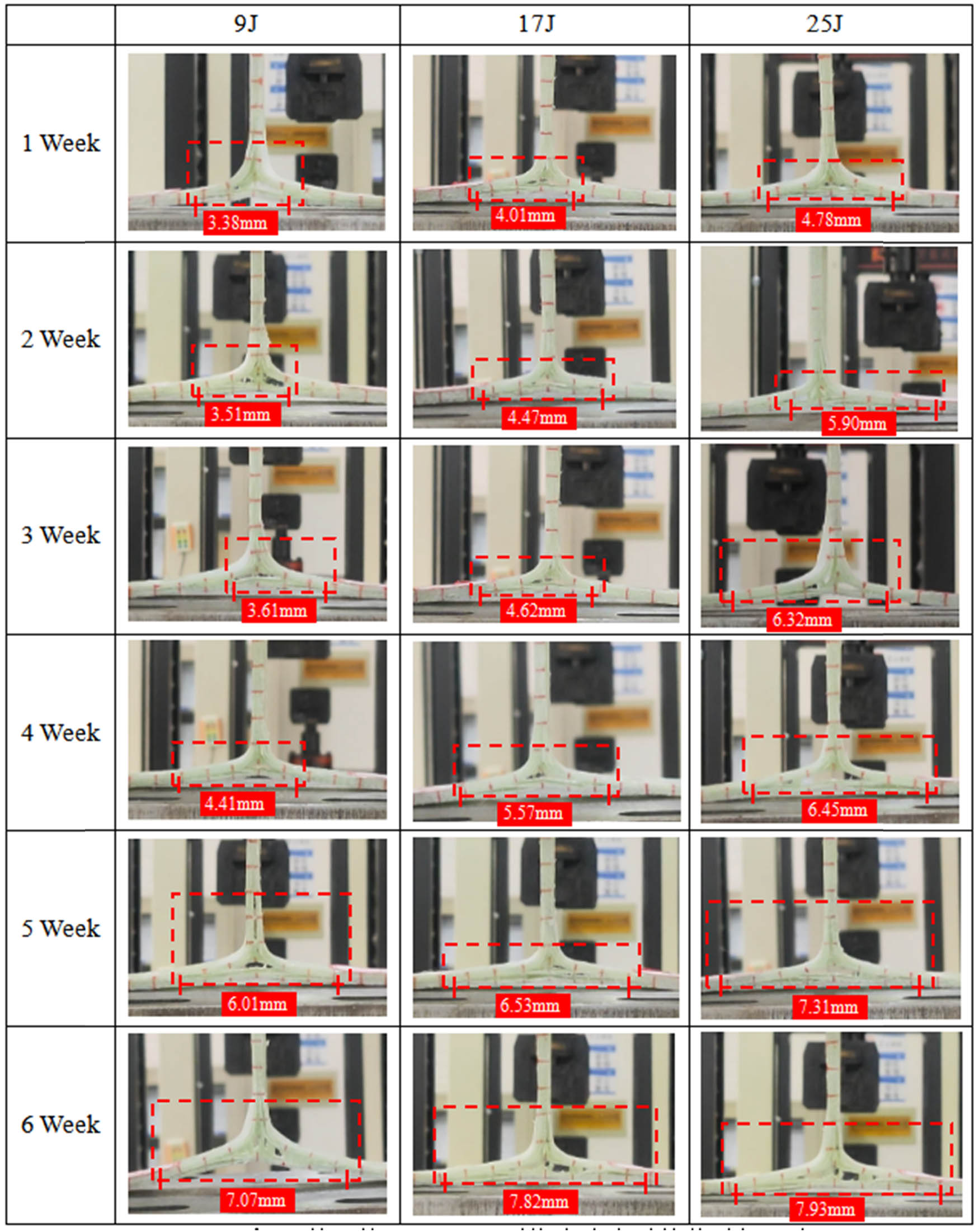
Tensile damage morphology after hydrothermal aging at 25°C.

Tensile damage morphology after hydrothermal aging at 60°C.
Horizontal crack length of GFRP T-joints after hydrothermal aging at 25°C
| Aging time (week) | Horizontal crack length (mm) | ||
|---|---|---|---|
| 9 J | 17 J | 25 J | |
| 1 | 3.38 | 4.01 | 4.78 |
| 2 | 3.51 | 4.47 | 5.90 |
| 3 | 3.61 | 4.62 | 6.32 |
| 4 | 4.41 | 5.57 | 6.45 |
| 5 | 6.01 | 6.53 | 7.31 |
| 6 | 7.07 | 7.82 | 7.93 |
Horizontal crack length of GFRP T-joints after hydrothermal aging at 60°C
| Aging time (week) | Horizontal crack length (mm) | ||
|---|---|---|---|
| 9 J | 17 J | 25 J | |
| 1 | 4.25 | 4.51 | 5.08 |
| 2 | 4.57 | 4.98 | 6.07 |
| 3 | 5.19 | 6.41 | 6.78 |
| 4 | 6.12 | 6.88 | 7.12 |
| 5 | 6.51 | 7.22 | 7.49 |
| 6 | 7.31 | 7.90 | 8.17 |
Figure 12 shows the force–displacement curves of different specimens under tensile test. Further, Figure 13 compares the peak forces of different types of specimens when stretched after impact. Under the same impact energy and aging time, the peak tensile load of the T-joint under the condition of 60°C damp heat aging is lower than that of other specimens at 25°C. Compared with the specimens with six aging period at 25°C, the specimens at 60°C and 1/2/3/4/5/6 week decrease by 7.88/26.80/30.33/26.22/25.99/31.14% in maximum force.

Force–displacement curves of all cases: (a) at 25°C and 10 J, (b) at 60°C and 9 J, (c) at 25°C and 17 J, (d) at 60°C and 17 J, (e) at 25°C and 25 J, (f) at 60°C and 25 J.

Comparison of GFRP T-joints under the impact energy of (a) 9 J, (b) 17 J, and (c) 25 J on ultimate force.
3.2.3 Residual strength of GFRP T-joints at different impact energies
The specimen has typical brittle material characteristics, which can be verified by the sharp decline of the force–displacement curve near the limit value as shown in Figure 12. First, the slope of specimens barely changed before reaching the limit, due to the deformation of the specimens being mainly elastic deformation. Then, the contact force sharply drops due to fiber breakage at the deltoid, and damage to the sample includes interlaminar delamination and fiber breakage. At low incidence energy (9 J), failure of the specimens during the tensile test occurs in the deltoid, but with the climb of the processing temperature, destruction extends to the skin. In the tensile test after high-energy impact (17 and 25 J), the degree of damage increased slightly due to the increase of impact energy, but it increased greatly due to the increase of aging time. At the same processing conditions, with the impact energies of 7 J/9 J/25 J, the peak tensile loads after impact are 376.49 N/328.67 N/246.59 N, which are reduced by 12.70% and 34.50%, respectively. This means that in a hydrothermal aging treatment, the mechanical properties and residual strength of the T-joint are significantly reduced.
4 Conclusion
To investigate the mechanical behavior of GFRP joints after hygrothermal aging, multiple groups of specimens based on the combination of aging temperature and time are subjected to low-velocity impact and post-impact tensile loads. According to the experimental results, involving typical response history and critical failure morphologies, the following conclusions can be drawn:
The structural strength of GFRP T-joints reduces greatly after hydrothermal aging since the erosion of internal resin induces a weakened interfacial bonding capability between fiber and matrix, especially in the deltoid area.
The significant degradation of impact strength and stiffness of GFRP T-joints after hydrothermal aging is reflected in a drop in peak force and an increase in failure displacement. Furthermore, the performance of T-joints decreases with the increase of aging time and temperature. Compared with 25–1–25 J in LVI, the peak force of 60–6–25 J decreased by 37.5%, while the failure displacement increased by 56.5%.
The residual strength of T-joints under post-impact tension decreases with the increase of impact energy and aging degree. During the failure process, the interlaminar cracks in the deltoid propagate in the horizontal and vertical directions, and there is a large gap in horizontal crack length between aged and non-aged T-joints. Compared with the T-joints at 25°C for 1 week and at 65°C for 6 weeks subjected to the impact of 25 J, the horizontal crack length of the latter in the deltoid area has increased by 60.8%, from 5.08 to 8.17 mm.
Acknowledgements
This work was sponsored by Foundation of Jiangxi Province of China Educational Committee (GJJ2201503, GJJ201907), and Innovative Projects of NIT (YC2024-S876, YC2024-S886, YC2024-S874).
-
Funding information: This work was sponsored by Foundation of Jiangxi Province of China Educational Committee (GJJ2201503, GJJ201907), and Innovative Projects of NIT (YC2024-S876, YC2024-S886, YC2024-S874).
-
Author contributions: Peiyu You: Conceptualization, Methodology, Software Validation, Formal analysis, Investigation, Resources, Data Curation, Writing – Original Draft, Writing – Review & Editing, Visualization, Supervision, Project administration, Funding acquisition. Jixiang Luo: Formal analysis, Investigation, Resources, Data Curation, Writing – Original Draft, Writing – Review & Editing, Visualization, Supervision, Project administration. Cuilong Liu: Conceptualization, Methodology, Investigation, Resources, Data Curation, Writing – Review & Editing, Visualization, Supervision, Project administration, Funding acquisition. Xiaobang Yao, Kaixin Xu, Mingjie Li, and Ye Wu: Data Curation, Writing – Original Draft, Writing – Review & Editing, Visualization.
-
Conflict of interest: Authors state no conflict of interest.
References
(1) Liu Y, Li M, Lu X, Zhu X. Failure mechanism and strength prediction model of T-joint of composite sandwich structure. Metals. 2021;11(8):1197.10.3390/met11081197Search in Google Scholar
(2) Wan Y, Lu W, Li H, Huang Y, Lei Z, Yang B. Tensile behavior of the bolt-jointed GFRP after low‐velocity impact. Polym Compos. 2023;44(5):2645–55.10.1002/pc.27267Search in Google Scholar
(3) Jagadeesh P, Puttegowda M, Thyavihalli Girijappa YG, Shivanna P, Rangappa SM, Siengchin S. Investigations on physical, mechanical, morphological and water absorption properties of ramie/hemp/kevlar reinforced vinyl ester hybrid composites. J Vinyl Addit Technol. 2023;29(3):555–67.10.1002/vnl.22008Search in Google Scholar
(4) Li H, Jiang C, Wu Y, Huang Y, Wan Y, Chen R. Experimental study on the low-velocity impact failure mechanism of foam core sandwich panels with shape memory alloy hybrid face-sheets. Sci Eng Compos Mater. 2021;28(1):592–604.10.1515/secm-2021-0059Search in Google Scholar
(5) Shen W, Wang Y, Yang J, Wang N, Shen W, Cai Y, et al. Ultimate bearing capacity analysis and bio-inspired optimization design of marine composite T-joint. J Compos Mater. 2024;58(3):377–99.10.1177/00219983231224046Search in Google Scholar
(6) Thawre MM, Dubey A, Verma KK, Peshwe DR, Jagannathan N, Manjunatha CM. A study on the fatigue life of a composite T-joint subjected to transport aircraft spectrum loads. Trans Indian Inst Met. 2016;69(2):409–13.10.1007/s12666-015-0794-3Search in Google Scholar
(7) Guo S, Li W. Numerical analysis and experiment of sandwich T-joint structure reinforced by composite fasteners. Compos Part B: Eng. 2020;199:108288.10.1016/j.compositesb.2020.108288Search in Google Scholar
(8) Zhang T, Luo Z, Li K, Cheng X. Experimental and numerical investigation of prepreg-RTM co-curing molding composite bolted T-joint under bending load. Polymers. 2024;16(7):1018.10.3390/polym16071018Search in Google Scholar PubMed PubMed Central
(9) Wagih A, Mahmoud HA, Lubineau G. 3D printed auxetic metal stiffener for lightweight metal–composite T-joints with high strength and toughness. Mater Des. 2024;241:112963.10.1016/j.matdes.2024.112963Search in Google Scholar
(10) Zhou J, Zhao Z, Shi Y, Wang X, Chen X, Shan C. Hail impact responses and residual tensile properties of CFRP T-joints. Chin J Aeronaut. 2023;36(7):430–43.10.1016/j.cja.2023.03.005Search in Google Scholar
(11) Bai J, Dong C, Xiong J, Luo C, Chen D. Progressive damage behaviour of RTM-made composite T-joint under tensile loading. Compos Part B. 2018;160:488–97.10.1016/j.compositesb.2018.12.069Search in Google Scholar
(12) Mouritz AP. Structural properties of z-pinned carbon-epoxy T-joints in hot-wet environment. J Compos Mater. 2014;48(23):2905–14.10.1177/0021998313503390Search in Google Scholar
(13) Chen H, Li M, Shen Z, Zhang Y, Zhu Y, Wu Y. Experimental investigation on tensile behavior of CFRP bolted joints subjected to hydrothermal aging. e-Polymers. 2024;24(1):20230183.10.1515/epoly-2023-0183Search in Google Scholar
(14) Liu Y, Wu Y. Influence of hydrothermal aging on the mechanical performance of foam core sandwich panels subjected to low-velocity impact. Sci Eng Compos Mater. 2022;29(1):9–22.10.1515/secm-2022-0003Search in Google Scholar
(15) Barzegar M, Moallem MD, Mokhtari M. Progressive damage analysis of an adhesively bonded composite T-joint under bending, considering micro-scale effects of fiber volume fraction of adherends. Compos Struct. 2021;258:113374.10.1016/j.compstruct.2020.113374Search in Google Scholar
(16) Wan Y, Hu W, Yang B, Zhao X, Xian G, Yuan Y, et al. On-line tensile damage monitoring of WGF/epoxy T-joint by the embedded MWCNT@WGF sensor. Compos Commun. 2021;23:100541.10.1016/j.coco.2020.100541Search in Google Scholar
(17) Chuyang L, Shuai W, Weidong L, Zhao L, Pan L. Mechanical properties of composite T-joints subjected to laser ablation. Compos Struct. 2022;294:115791.10.1016/j.compstruct.2022.115791Search in Google Scholar
(18) Zhang W, Gu B, Sun B. Transverse impact behaviors of 3D braided composites T-beam at elevated temperatures. J Compos Mater. 2016;50(28):3961–71.10.1177/0021998316630394Search in Google Scholar
(19) Guowei L, Ertai C, Ben J, Zhang X, Wang W, Huang H. Mechanical properties and failure behaviors of T1100/5405 composite T-joint under in-plane shear load coupled with initial defect and high-temperature. Compos Struct. 2024;328:117722.10.1016/j.compstruct.2023.117722Search in Google Scholar
(20) Murdy P, Hughes S, Miller AD, Presuel-Moreno JF, Bonheyo TG, Gunawan B, et al. Static and fatigue characterization of large composite T-bolt connections in marine hygrothermal environments. J Mar Sci Eng. 2023;11(12):2309.10.3390/jmse11122309Search in Google Scholar
(21) Wan Y, Wang L, Liu Y, Wu Y. Experimental investigation on the low‐velocity impact response and the residual strength of CFRP tubes. Polym Compos. 2024;45(10):8677–93.10.1002/pc.28368Search in Google Scholar
(22) Tu Y, Li X, Huang H, Chen C, Liu G, Liu Y, et al. Experimental evaluation on compression-after-impact behavior of perforated sandwich panel comprised of foam core and glass fiber reinforced epoxy hybrid facesheets. e-Polymers. 2024;24(1):20240021.10.1515/epoly-2024-0021Search in Google Scholar
(23) Wu Y, You P, Hua W, Liu C, Zhang S, Liu Y. Experimental investigation on damage mechanism of GFRP laminates embedded with/without steel wire mesh under low-velocity-impact and post-impact tensile loading. e-Polymers. 2024;24(1):20240002.10.1515/epoly-2024-0002Search in Google Scholar
(24) You P, Chen H, Li M, Wu Y. A simulative study on the effect of friction coefficient and angle on failure behaviors of GLARE subjected to low-velocity impact. Sci Eng Compos Mater. 2023;30(1):20220194.10.1515/secm-2022-0194Search in Google Scholar
(25) Wu Y, Wan Y. The low-velocity impact and compression after impact (CAI) behavior of foam core sandwich panels with shape memory alloy hybrid face-sheets. Sci Eng Compos Mater. 2019;26(1):517–30.10.1515/secm-2019-0034Search in Google Scholar
(26) Hou W, Xu X, Hu C, Huo Y, Tong L. Failure characteristics of composite metallic foam core hat-shaped tubular T-joints under static and impact loading. Thin-Walled Struct. 2022;174:109064.10.1016/j.tws.2022.109064Search in Google Scholar
(27) Jin X, Zhang J, Li M, Wu Y. Experimental and simulative investigation on the mechanical behavior of GFRP T‐joints subjected to low‐velocity‐impact and post‐impact tensile loading. Polym Compos. 2024;45(4):3055–66.10.1002/pc.27970Search in Google Scholar
(28) Wu Y, You P, Li M, Wan Y. An experimental study on the failure mechanism of local-strengthening glass fiber reinforced polymer T-joints under/after the low-velocity impact loading. J Compos Mater. 2023;57(30):4699–708.10.1177/00219983231216435Search in Google Scholar
(29) You P, Chen C, Wu Y, Zhang B, Tang X, Zhu D, et al. An experimental study on the failure and enhancement mechanism of bolt-strengthening GFRP T-joint subjected to tensile loading. Sci Eng Compos Mater. 2022;29(1):466–72.10.1515/secm-2022-0169Search in Google Scholar
(30) ASTM. D7136/D7136M-15 standard test method for measuring the damage resistance of a fiber-reinforced polymer matrix composite to a drop-weight impact event. West Conshohocken, PA: ASTM International; 2015.Search in Google Scholar
(31) Mamalis D, Floreani C, Brádaigh CMÓ Influence of hygrothermal ageing on the mechanical properties of unidirectional carbon fibre reinforced powder epoxy composites. Compos Part B: Eng. 2021;225:109281.10.1016/j.compositesb.2021.109281Search in Google Scholar
© 2024 the author(s), published by De Gruyter
This work is licensed under the Creative Commons Attribution 4.0 International License.
Articles in the same Issue
- Research Articles
- Flame-retardant thermoelectric responsive coating based on poly(3,4-ethylenedioxythiphene) modified metal–organic frameworks
- Highly stretchable, durable, and reversibly thermochromic wrapped yarns induced by Joule heating: With an emphasis on parametric study of elastane drafts
- Molecular dynamics simulation and experimental study on the mechanical properties of PET nanocomposites filled with CaCO3, SiO2, and POE-g-GMA
- Multifunctional hydrogel based on silk fibroin/thermosensitive polymers supporting implant biomaterials in osteomyelitis
- Marine antifouling coating based on fluorescent-modified poly(ethylene-co-tetrafluoroethylene) resin
- Preparation and application of profiled luminescent polyester fiber with reversible photochromism materials
- Determination of pesticide residue in soil samples by molecularly imprinted solid-phase extraction method
- The die swell eliminating mechanism of hot air assisted 3D printing of GF/PP and its influence on the product performance
- Rheological behavior of particle-filled polymer suspensions and its influence on surface structure of the coated electrodes
- The effects of property variation on the dripping behaviour of polymers during UL94 test simulated by particle finite element method
- Experimental evaluation on compression-after-impact behavior of perforated sandwich panel comprised of foam core and glass fiber reinforced epoxy hybrid facesheets
- Synthesis, characterization and evaluation of a pH-responsive molecular imprinted polymer for Matrine as an intelligent drug delivery system
- Twist-related parametric optimization of Joule heating-triggered highly stretchable thermochromic wrapped yarns using technique for order preference by similarity to ideal solution
- Comparative analysis of flow factors and crystallinity in conventional extrusion and gas-assisted extrusion
- Simulation approach to study kinetic heterogeneity of gadolinium catalytic system in the 1,4-cis-polyisoprene production
- Properties of kenaf fiber-reinforced polyamide 6 composites
- Cellulose acetate filter rods tuned by surface engineering modification for typical smoke components adsorption
- A blue fluorescent waterborne polyurethane-based Zn(ii) complex with antibacterial activity
- Experimental investigation on damage mechanism of GFRP laminates embedded with/without steel wire mesh under low-velocity-impact and post-impact tensile loading
- Preparation and application research of composites with low vacuum outgassing and excellent electromagnetic sealing performance
- Assessing the recycling potential of thermosetting polymer waste in high-density polyethylene composites for safety helmet applications
- Mesoscale mechanics investigation of multi-component solid propellant systems
- Preparation of HTV silicone rubber with hydrophobic–uvioresistant composite coating and the aging research
- Experimental investigation on tensile behavior of CFRP bolted joints subjected to hydrothermal aging
- Structure and transition behavior of crosslinked poly(2-(2-methoxyethoxy) ethylmethacrylate-co-(ethyleneglycol) methacrylate) gel film on cellulosic-based flat substrate
- Mechanical properties and thermal stability of high-temperature (cooking temperature)-resistant PP/HDPE/POE composites
- Preparation of itaconic acid-modified epoxy resins and comparative study on the properties of it and epoxy acrylates
- Synthesis and properties of novel degradable polyglycolide-based polyurethanes
- Fatigue life prediction method of carbon fiber-reinforced composites
- Thermal, morphological, and structural characterization of starch-based bio-polymers for melt spinnability
- Robust biaxially stretchable polylactic acid films based on the highly oriented chain network and “nano-walls” containing zinc phenylphosphonate and calcium sulfate whisker: Superior mechanical, barrier, and optical properties
- ARGET ATRP of styrene with low catalyst usage in bio-based solvent γ-valerolactone
- New PMMA-InP/ZnS nanohybrid coatings for improving the performance of c-Si photovoltaic cells
- Impacts of the calcinated clay on structure and gamma-ray shielding capacity of epoxy-based composites
- Preparation of cardanol-based curing agent for underwater drainage pipeline repairs
- Preparation of lightweight PBS foams with high ductility and impact toughness by foam injection molding
- Gamma-ray shielding investigation of nano- and microstructures of SnO on polyester resin composites: Experimental and theoretical study
- Experimental study on impact and flexural behaviors of CFRP/aluminum-honeycomb sandwich panel
- Normal-hexane treatment on PET-based waste fiber depolymerization process
- Effect of tannic acid chelating treatment on thermo-oxidative aging property of natural rubber
- Design, synthesis, and characterization of novel copolymer gel particles for water-plugging applications
- Influence of 1,1′-Azobis(cyclohexanezonitrile) on the thermo-oxidative aging performance of diolefin elastomers
- Characteristics of cellulose nanofibril films prepared by liquid- and gas-phase esterification processes
- Investigation on the biaxial stretching deformation mechanism of PA6 film based on finite element method
- Simultaneous effects of temperature and backbone length on static and dynamic properties of high-density polyethylene-1-butene copolymer melt: Equilibrium molecular dynamics approach
- Research on microscopic structure–activity relationship of AP particle–matrix interface in HTPB propellant
- Three-layered films enable efficient passive radiation cooling of buildings
- Electrospun nanofibers membranes of La(OH)3/PAN as a versatile adsorbent for fluoride remediation: Performance and mechanisms
- Preparation and characterization of biodegradable polyester fibers enhanced with antibacterial and antiviral organic composites
- Preparation of hydrophobic silicone rubber composite insulators and the research of anti-aging performance
- Surface modification of sepiolite and its application in one-component silicone potting adhesive
- Study on hydrophobicity and aging characteristics of epoxy resin modified with nano-MgO
- Optimization of baffle’s height in an asymmetric twin-screw extruder using the response surface model
- Effect of surface treatment of nickel-coated graphite on conductive rubber
- Experimental investigation on low-velocity impact and compression after impact behaviors of GFRP laminates with steel mesh reinforced
- Development and characterization of acetylated and acetylated surface-modified tapioca starches as a carrier material for linalool
- Investigation of the compaction density of electromagnetic moulding of poly(ether-ketone-ketone) polymer powder
- Experimental investigation on low-velocity-impact and post-impact-tension behaviors of GFRP T-joints after hydrothermal aging
- The repeated low-velocity impact response and damage accumulation of shape memory alloy hybrid composite laminates
- Exploring a new method for high-performance TPSiV preparation through innovative Si–H/Pt curing system in VSR/TPU blends
- Large-scale production of highly responsive, stretchable, and conductive wrapped yarns for wearable strain sensors
- Preparation of natural raw rubber and silica/NR composites with low generation heat through aqueous silane flocculation
- Molecular dynamics simulation of the interaction between polybutylene terephthalate and A3 during thermal-oxidative aging
- Crashworthiness of GFRP/aluminum hybrid square tubes under quasi-static compression and single/repeated impact
- Review Articles
- Recent advancements in multinuclear early transition metal catalysts for olefin polymerization through cooperative effects
- Impact of ionic liquids on the thermal properties of polymer composites
- Recent progress in properties and application of antibacterial food packaging materials based on polyvinyl alcohol
- Additive manufacturing (3D printing) technologies for fiber-reinforced polymer composite materials: A review on fabrication methods and process parameters
- Rapid Communication
- Design, synthesis, characterization, and adsorption capacities of novel superabsorbent polymers derived from poly (potato starch xanthate-graft-acrylamide)
- Special Issue: Biodegradable and bio-based polymers: Green approaches (Guest Editors: Kumaran Subramanian, A. Wilson Santhosh Kumar, and Venkatajothi Ramarao)
- Development of smart core–shell nanoparticles-based sensors for diagnostics of salivary alpha-amylase in biomedical and forensics
- Thermoplastic-polymer matrix composite of banana/betel nut husk fiber reinforcement: Physico-mechanical properties evaluation
- Special Issue: Electrospun Functional Materials
- Electrospun polyacrylonitrile/regenerated cellulose/citral nanofibers as active food packagings