Thermal–mechanical coupling deformation difference analysis for the flexspline of a harmonic drive
-
Yangfan Li


Abstract
The flexspline (FS) of the harmonic drive (HD) is subjected to thermal load and force load during operation, leading to the deformation difference between the inner and outer surfaces of the FS. As a result, the transmission performance of the HD assembly decreases. To overcome this problem, the thermal–mechanical coupling deformation mechanism of the FS is analyzed, and then the influence of the deformation difference on the transmission accuracy of the HD is studied in this article. On this basis, the structural parameters of the wave generator are optimized to eliminate actual backlash and to improve the actual transmission accuracy. Finally, the effectiveness of the calculation method proposed in this article was proved by the prototype test.
1 Introduction
A harmonic drive (HD) is widely used in complicated mechanical systems, such as machine tools, robots, and spacecraft, due to its large transmission ratio, straightforward structure, and small size. An HD consists of three components, namely, a rigid “circular spline (CS),” an elliptical “wave generator (WG),” and a non-rigid “flexspline (FS).” CS has inner teeth, and FS has outer teeth. WG has an elliptical ball bearing. The operation of HD depends on the harmonic elastic deformation of the FS.
HD was invented as a practical application by American engineers [1,2]. To improve transmission performance, many researchers have conducted studies to improve the tooth profiles of HD [3,4,5]. The main tooth profiles of HD are the involute profile, S profile, and double circular arc profile. The objective of design optimization is to increase the meshing area to improve the load-carrying capacity and transmission stability [6]. In Kayabasi and Erzincanli [4], the authors increased the fatigue strength of the tooth root by improving the tooth profile parameters, and the torsional stiffness of the gear was also enhanced [4]. Zhu et al. [7] established a kinematic model of HD to discuss the relationship between the cone angle of FS and the engagement profile, aiming at the different neutral curves in cross sections perpendicular to the axis made by the taper deformation under FS of HD produced by the cam WG. Liu et al. [8] established a design method for the space tooth profile of CS, which spatially engaged with deformed FS, and a calculation method of backlash between engaged teeth surfaces. To enable more teeth engagement, a complete method to design a tooth profile and its backlash assessment in an HD was presented by Pacana et al. [9].
The strain calculation of FS is very important in the design and optimization of the HD system [10]. Pleguezuelos et al. [11] reported some results on conventional internal gearing. They used elastic potential energy in calculating load sharing and contact stress in high-contact-ratio internal spur gears. Later, Sahoo and Maiti [12] also produced similar results using different methods and took the effect of the variation in the rim-thickness into account in load-sharing patterns. Wang et al. [13] studied the stress calculation methods for short FS and proposed a rapid stress calculation method for short HD.
In addition to the above studies, an experimental method was proposed to investigate the effect of the driving speed on the deformation characteristics of FS, and the comparison results revealed that the radial displacement of FS is composed of harmonic and random components [14]. Chen et al. [15] calculated the circumferential strain using Hooke’s law in the assembly state. Tian et al. [16] proposed a multibody contact model of flexible bearing, which was developed with ANSYS and used to study load distribution.
Owing to the installation error, manufacturing error, elastic deformation, thermal deformation, and other factors, the straight bevel gear pair will incur the serious phenomenon of meshing interference and impact in the meshing process. Therefore, it is necessary to design a suitable modification tooth to improve the gear pair’s transmission performance and enhance its bearing capacity. Zhang et al. [17] considered elastic deformation of gear pair, obtained the optimal isometric modification parameters using orthogonal design, and then used the optimal isometric modification parameters and symmetric crowned modification parameters to modify the tooth separately. In terms of thermal deformation analysis of gears, Lee et al. [18] measured thermal deformation through the uncertainty of material properties and proposed a precise and efficient tooth profile analysis method. Lu and Tang [19] proposed the thermal time-varying stiffness model and the thermal time-varying backlash model of tooth deformation, and the influencing mechanism of temperature on the tooth profile error, mesh stiffness, total deformation, and backlash was revealed. Backlash plays a significant role in gear design and gear dynamic analysis. The time-varying backlash increases with an increase in torque load and a decrease in rotation speed and tooth surface temperature [20].
From the above studies, it is evident that the deformation analysis of the FS under a non-working state and the optimization of the parameters of the tooth profile have been extensively studied. Nevertheless, the traditional HD model is often simplified by taking the deformation of the neutral line in FS as the deformation of FS. The deformations of the inner and outer surfaces of FS are not taken into consideration. The transmission performance of HD is influenced by these simplifications. Additionally, the HD produces thermal deformation during actual operation, which also influences the meshing effect between the gear teeth. Therefore, it is crucial to study the deformation of FS under the action of thermal–mechanical coupling and modify the actual position of the tooth profile by considering the deformation difference between the inner and outer surfaces of FS.
At present, the research on the thermal deformation of gear meshing mainly focuses on the optimization of the tooth profile to improve the degree of gear meshing. However, the inertia moment of the longitudinal section of the tooth is about 10 times that of the section in the middle of the gear. When the FS is deformed, the tooth profile is unchanged [21]. The previous analysis method for the thermal deformation of the tooth profile is not fully applicable to the actual situation of the HD.
In this article, the thermal–mechanical coupling deformation of HD was proposed to calculate the actual deformation of FS. The deformation difference between the inner and outer surfaces of FS was established, the actual deformation curve of the tooth profile is solved by considering this deformation difference. Subsequently, the actual tooth profile of the FS was made consistent with the theoretical tooth profile by optimizing the structure of WG to ensure the transmission accuracy of the HD during operations.
This article is organized as follows: the calculation of thermal load and heat transfer coefficient for HD is described in Section 2. The force deformation of the FS is analyzed in Section 3. Section 4 illustrates the solution of the thermal–mechanical coupling deformation difference of FS. Section 5 demonstrates the application of the proposed method in case. The conclusions are given in Section 6.
2 Calculation of the thermal load and heat transfer coefficient of HD
As shown in Figure 1, during the operation of the HD, on the one hand, it is loaded by the force of WG and flexible bearing, resulting in flexible deformation of FS; on the other hand, working heat will also lead to deformation of FS, including gear meshing heat and flexible bearing heat. From these initial conditions, the thermal deformation and force deformation of FS can be calculated. Furthermore, the deformation difference between the inner and outer surfaces of the FS can be analyzed.
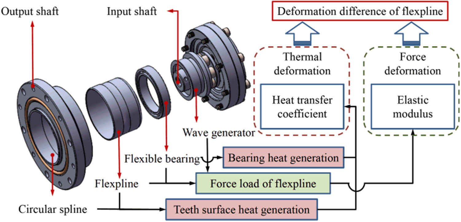
FS deformation principle of HD.
2.1 Calculation of heat generation of tooth meshing of HD
The meshing friction heat flux of the gear teeth is mainly determined by the sliding friction coefficient of the tooth surface, the relative sliding speed of the tooth surface, and the contact stress of the tooth surface [22].
where q m is the meshing friction heat flux, γ represents the conversion coefficient of friction energy into heat energy, μ and σ p are the sliding friction coefficient and average contact stress of the tooth surface, respectively, and v r is the relative sliding speed of the tooth surface.
The sliding friction coefficient at any meshing position is [23]
where σ H is the maximum contact stress of the tooth surface, v 1, v 2 are the tangential speed of the driving gear and driven gear at the meshing point, respectively, R 1 and R 2 are the equivalent radii of driving gear and driven gear respectively, as shown in Figure 2, η oil represents dynamic viscosity of lubricating oil, and R a represents tooth surface roughness.

A simplified contact model.
When the running conditions are the same, the contact state between the teeth can be simulated by a pair of rollers [24], with ρ 1 and ρ 2 being the curvature radii at the contact line of two cylinders, respectively, as shown in Figure 3.
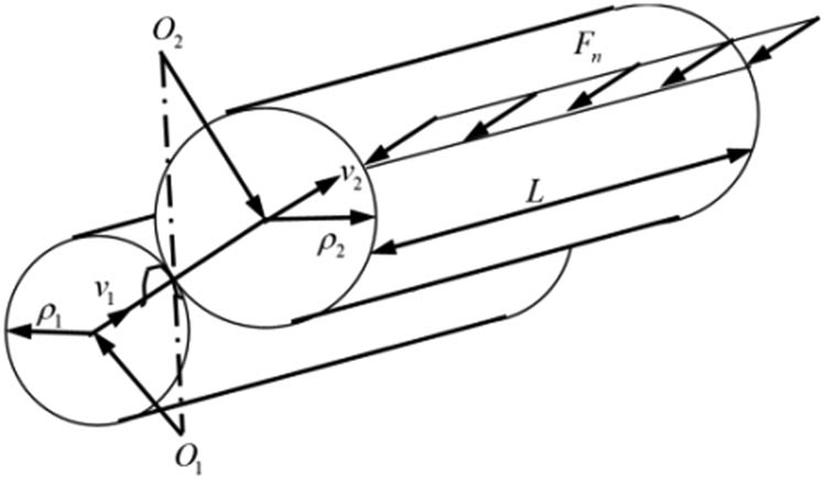
Cylindrical contact.
According to the Hertz theory [25], the maximum contact stress is given as
where ρ, μ, and E, respectively, represent the radius of curvature, Poisson’s ratio, and the modulus of elasticity, subscript 1 represents the FS, and subscript 2 represents the CS. L is the length of the contact line between the FS and the CS. F n is the nominal normal load of the gear teeth, and the relationship with the circumferential load (F t ) on the FS can be described using the following equations:
where α is the pressure angle of the FS, N is the number of teeth involved in meshing at the same time, and T and r b are the torque and index circle radius of the FS, respectively.
2.2 Calculation of heat generation of the flexible bearing of HD
Flexible rolling bearings are mostly used in the HD. Based on the coupling mechanism between their nonlinear mechanical characteristics and thermal effects, a dynamic bearing heat generation calculation model is established, which comprehensively considers factors such as force load and spin motion of rolling elements. Based on the Palmgren overall heat generation model, the bearing friction torque is divided into two components: the inner and outer ring M i and M o [26]
where Z is the number of rolling elements of the bearing, D b represents the diameter of the rolling element, D i and d o are the diameters of the contact points between the inner and outer raceways with the rolling elements, respectively, d m and n are the pitch, diameter and speed of bearing, respectively. f 0 is the coefficient related to bearing type and lubrication method, P i, P o represent the calculated load of the friction torque of the inner and outer rings of the bearing, and the coefficient f 1 depends on the bearing type and load.
here, C 0 is the rated static load of the bearing, and P 0 represents the equivalent static load of bearing
where F a and F r are the axial and radial load of the bearing, respectively. During the operation of the HD, the flexible bearing is mainly subjected to the force of the radial load. The calculations are given in detail in Section 3.
When the bearing rotates, the rolling element spins to generate friction torque
where μ si represents the sliding friction factor of the rolling element and the inner ring raceway, a ij is the major axis of the Hertz contact between the rolling element and the inner ring raceway, and L(K)ij is the second type of complete integration of the rolling element and the inner ring raceway Hertz contact.
The frictional heat generation of the contact area between the single rolling element and the inner and outer rings of the bearing can be described as follows:
where ω sij is the spin angular velocity of the rolling element.
According to Burton’s theory [27], the effect of the cage and the guide ring on heat generation is ignored, the bearing friction heat generation is distributed to the rolling elements, and the inner and outer rings contact raceways at 1:1, and then the heat generation of each part of the bearing can be modeled using the following equations:
here, H i, H o, and H b are the heat generation of the inner, outer ring raceway surfaces, and rolling element surfaces of the bearing, respectively.
2.3 Heat transfer coefficient on the end face of gear teeth
The convective heat transfer on the end face of the gear teeth can be simplified as the convective heat transfer analysis of the rolling disc. The flow of lubricating oil along the disc surface can be divided into a laminar flow, transition layer flow, and turbulent flow. The convective heat transfer coefficient of the end face of the gear tooth is determined by the Nusselt number (Nu), Reynolds number (Re), Prandtl number (Pr), and the local radius (R c) of the end face [28]
The Reynolds number is formulated as follows:
where u liquid is the coolant speed, l contact represents the characteristic length of the contact surface, and v liquid is the kinematic viscosity of the coolant.
When Re < 1.95 × 10⁵, the flow on the end face of the gear teeth belongs to laminar flow
among the formulas, λ f is the thermal conductivity of the coolant, ρ f and c f are the coolant density and specific heat capacity, respectively, ω represents the angular speed of rotation of the FS.
When 1.95 × 10⁵ < Re < 2.5 × 10⁵, the end face of the gear teeth is in the transition layer flow state
When Re >2.5 × 10⁵, the flow on the end face of the gear teeth belongs to turbulence flow
2.4 Heat transfer coefficient on the circumferential surface of the tooth tip
The convective heat transfer coefficient between the circumferential surface of the tooth tip and the lubricating oil can be approximately equivalent to the lubricating oil passing across the elongated flat plate laterally [29]. The Reynolds number and Nusselt number of the lubricating oil flowing on the circumferential surface of the tooth tip are shown as follows:
where r a is the radius of the tip circle of FS. Therefore, the heat transfer coefficient of the tooth face circumferential flow is formulated as follows:
2.5 Heat transfer coefficient of bearing lubrication
After the lubricating oil passes through the bearing, a part of the grease adheres to the rolling element and the inner and outer rings of the bearing to cool and lubricate. The other part will remove the heat and disperse it into the air. The heat dissipation coefficient has been shown in [30]
where D a is the size of the geometric characteristics of the heat exchange, and the Reynolds number is formulated as
3 Analysis of force and deformation of FS
3.1 Calculation of force load on FS
When the FS is assembled with a WG, its contour shape changes, and the deformation curve is determined by the WG. In this article, the cosine cam WG is selected as an example, and the deformation of the FS is shown in Figure 4.

Deformation curve of FS under cosine WG.
Assuming that the inner surface of the FS is connected with the WG, the maximum radial deformation of the inner surface of the FS is w 0. The deformation of the inner surface under the WG is
where ϕ 0 represents the rotation angle between the deformation curves of the FS with the long axis of WG. r b denotes the inner surface radius of FS before deformation. Because the FS has a certain thickness, the increase of the tooth top radius on the outer surface of the FS will be different from that on the inner surface of the FS. The actual increase of the tooth top circle circle radius will be less than w 0·cos(2ϕ 0) [31]; that is, there is a deformation difference between the inner and outer surfaces of FS.
The simplified FS is a smooth cylindrical model, which does not consider the influence of the gear ring, boundary effect, the form of WG, and the distortion of the FS on the stress and strain. The usual method is to analyze the influence through experiments and then make some correction to the theoretical calculations [32]. The radial stress at the contact position between the FS and the WG is shown as follows:
where ν and E are Poisson’s ratio and the elastic modulus of FS, respectively. w 0 = w* × m, w*, and m are the radial deformation coefficient and modulus of the FS, respectively. δ represents the wall thickness of FS. C σ represents the normal stress coefficient [33].
3.2 Analysis of the relationship between deformation difference and transmission error
The FS rotates in the opposite direction during the rotation of the WG; the radial and circumferential deformation occur, but the deformations of the FS’s cross section are different. Theoretically, the difference between the long and short half-axes of the WG is equal to the maximum deformation of the FS’s neutral layer. However, the FS has a certain wall thickness. The spatial position change of the FS’s tooth profile is less than the maximum deformation of the neutral layer. Compared with the theoretical tooth profile, the actual tooth profile of FS is far from the tooth profile of CS; this also causes the actual backlash to be larger than the theoretical backlash (Figure 5) [34].

The influence factors of backlash.
Due to the deformation difference between the inner and outer surfaces of the FS, the actual tooth profile of FS is different from the theoretical tooth profile. The deformation differences between radial direction and tangential direction is Δw and Δv, respectively. If the deformation difference between the inner and outer surfaces of FS is not considered and the deformation of the neutral layer of FS is taken as the actual deformation of the FS, the fitting backlash between CS and FS will be smaller than the actual backlash, which will lead to the deviation in the calculation the tooth profile of CS. The backlash between FS and CS will be affected by the deformation difference. The relationship between transmission errors and backlash of HD is as follows [35]:
where j ϕ and j t express the transmission error and backlash, receptively, m is the modulus of meshing gears, and Z 1 represents the tooth number of FS. Obviously, as the backlash increases, transmission error increases. When calculating the tooth profile of CS, the actual tooth profile of FS should be considered to avoid the increase of initial backlash caused by the deformation difference, which will affect the accuracy of HD.
4 Calculation method of thermal–mechanical coupling deformation difference of FS
Based on the above analysis, the deformation difference between the inner and outer surfaces of FS affects the transmission accuracy of HD. The deformation difference of FS is considered in the thermal–mechanical coupling calculation method of HD.
In the actual operation process of HD, the temperature gradually increases, and the kinematic viscosity and Planck number of the lubricating fluid will also change, which will affect the calculation of HD thermal boundary conditions, resulting in the calculation error of the deformation difference between the inner and outer surfaces of FS at the thermal steady state. The deformation calculation method of FS based on the thermal–mechanical coupling is shown in Figure 6.

Technical route of thermal–mechanical coupling deformation analysis of FS.
From Figure 6, The thermal–mechanical coupling algorithm of HD is divided into the following steps:
The stress of FS is calculated by the maximum deformation and material properties of FS.
It is assumed that heat generation of HD mainly includes flexible bearing heat generation and tooth surface meshing heat generation. We set the speed of HD and calculate the heat output of the bearing according to the radial load of FS. On the other hand, the heat generation of the tooth surface is calculated according to the tangential load of FS.
The heat transfer coefficient and other thermal boundary conditions are calculated and input into ANSYS workbench together with the heat generation value to obtain the temperature field of HD under initial conditions.
The kinematic viscosity and Planck number of cooling water decrease with an increase of temperature, and the thermal conductivity increases with an increase of temperature. The kinematic viscosity of air increases with an increase of temperature, while the Planck number and kinematic viscosity of lubricating oil decrease with an increase of temperature. Therefore, with an increase in the temperature of the HD, the thermal boundary conditions of each stage are different. By consulting the mechanical design manual [36], according to the temperature field of each iteration, the Planck constant and other parameters are determined at the corresponding temperature to calculate the thermal boundary conditions in the next iterative. If the temperature difference is greater than 0.2°C [37], the Planck number and other parameters under the new temperature condition are adjusted, and the new thermal boundary conditions are brought into the ANSYS workbench to perform a thermal–mechanical coupling iterative calculation.
After several thermal–mechanical coupling iterations, until the temperature difference is less than the threshold, it can be considered that the HD has reached the thermal balance, and then the deformation difference between the inner and outer surfaces of the FS is outputted.
When the HD reaches a stable thermal state, the thermal boundary conditions need to be modified multiple times. Here, the ANSYS workbench and MATLAB are used in combination to set iterates during the temperature increase of the HD. The calorific value and thermal boundary conditions are calculated by MATLAB. The temperature fields and deformation of FS are simulated by the ANSYS workbench.
5 Verification by Example
The WH-CS14-type HD and the three-dimensional model are shown in Figure 7. At the initial moment, assume the initial temperature is 22°C, and the rotating speed of the WG is 2,000 rpm. According to the analysis in Sections 2 and 3, the calculated initial load and boundary conditions are shown in Table 1. S o and S i are the areas of outer and inner gear rings, respectively.

Structure diagram of HD.
Initial load and boundary conditions
| Initial load and boundary conditions | Value | Unit |
|---|---|---|
| Heat generated by teeth (q m) | 12,920 | W·m−2 |
| Heat generated in the contact area of rolling element and bearing outer ring (H o/S o) | 74,660 | W·m−2 |
| Heat generated in the contact area of rolling element and bearing inner ring (H i/S i) | 82,950 | W·m−2 |
| Rotating speed (v 1/2πr b) | 2,000 | rpm |
| Maximum deformation (w 0) | 0.44 | mm |
| Rated torque (T) | 7.8 | N·m |
| Heat transfer coefficient of gear teeth (h f) | 408.86 | W/(m2·K) |
| Heat transfer coefficient on the circumferential surface of the teeth (h d) | 454.58 | W/(m2·K) |
| Heat transfer coefficient of bearing lubrication (h z) | 31.49 | W/(m2·K) |
According to the calculation method in Section 4 and the initial data in Table 1, after five iterations, the modified value of each coefficient and the value of heat load are shown in Figure 8.

Data correction for each iteration. (a) Heat generated by teeth. (b) Heat transfer coefficient.
As is illustrated in Figure 8, when the HD approaches the thermal stable state, the heat generated by the tooth and the heat transfer coefficient of the surface of the teeth, gear teeth, and bearing lubrication increase with increasing temperature. The boundary condition data obtained from each iteration are inputted into the ANSYS workbench for analysis.
The temperature on the tooth surface of each calculation result is compared until the temperature increase of the HD is not evident; that is to say, after five iterations, the HD reaches the thermal equilibrium state. The temperature field of HD in the eventual thermal steady state is shown in Figure 9.

Temperature field of HD in thermal steady state.
As shown in Figure 9, under the action of thermal–mechanical coupling, the temperature of the teeth is the highest when the FS reaches the thermal steady state, reaching 51.8°C.
Using the sequential coupling analysis method, the temperature field is applied to the finite-element static analysis module, and the boundary conditions such as displacement constraints are applied to obtain the radial thermal elongation calculation results of the HD. After five iterations, the algorithm cycle is terminated, and the deformation of FS is shown in Figures 10 and 11.

Radial deformation of inner surface of FS.

Radial deformation of outer surface of FS.
As is displayed in Figures 10 and 11, the radial deformations of the inner and outer surfaces of FS are 0.353 and 0.346 mm, respectively, and the radial deformation difference of FS is 0.007 mm. Due to this difference in deformation, the actual spatial position of the tooth profile of the FS does not coincide with the theoretical position, which increases the backlash of the tooth engagement and affects the transmission accuracy.
To compensate for the increase in meshing backlash caused by the deformation difference of FS, the size of the cam is improved, and the long axis size of the elliptical cam is changed from 25.510 to 25.517 mm, depending on the deformation difference of FS. Meanwhile, the short axis size is changed from 24.630 to 24.623 mm, making the actual tooth profile of the FS coincide with the theoretical tooth profile as much as possible; thereby, the transmission accuracy of the HD can be improved. The HD prototypes before and after optimization are shown in Figure 12.

HD test prototype.
The comprehensive performance test platform of HD is shown in Figure 13. The main test equipment and parameters are as follows.

The comprehensive performance test platform of HD.
Comprehensive test bench: zrt-ii test bench, overall dimension: 2.6 m × 1.4 m × 1.05 m, linear movement accuracy: 0.01 mm, comprehensive mechanical accuracy: 0.03 mm.
Servo motor: SIEMENS 1FK7086-4CC71-1BA0, Rated speed: 2,000 rpm.
Angle sensor: Heidenhain MRP 5080, Angular error: ±0.5″/sp.
Torque sensor: Kistler 9,389 A, sensitivity: −135 pC/ft·lb.
The test platform is connected with the console to realize data acquisition and control signal transmission. The torque and speed of the motor are controlled by a converted input signal, and then HD is divided by the input shaft. The output shaft is connected with the motor at the other end, and the load is adjusted by the control platform. The torque and speed of the input shaft and output shaft are collected by the torque sensor, and the rotation angle of the shaft is collected by the angle sensor. Experimental data are transmitted to the test platform in real time, recorded on the host computer, and displayed in the form of tables and curves.
To measure the change of meshing backlash before and after optimization, the output end of HD is locked, the input end is turned to the end in one direction, and the rotation angle is recorded and then turned to the other direction until it cannot move. The rotation angle is recorded, and the difference between the two rotation angles is backlash. The sampling rate is set at 100 ms, and the rotation speed is set at 0.001 rpm. The reverse maximum value is generally set as 3% of the rated torque. When the torque is less than 1, 0.4 Nm is used as the test value considering the problem of compensating bearing friction; the detection results of the backlash of two HDs are shown in Figure 14.

Backlash test results of HD.
Figure 14 displays that the lower output angle is −2″, the upper output angle is 9″, and the backlash is 11″ before optimization and the lower output angle is −10″, the upper output angle is 0″, and the backlash is 10″ after optimization.
The test results of the transmission error of HD before and after optimization are shown in Figure 15. It can be seen that the backlash is reduced 1″ after optimization.

Transmission error of HD: (a) before optimization and (b) after optimization.
The abscissa represents the rotation angle of HD, i.e., 10 to 370 degrees. The ordinate represents the transmission error value in the process of one revolution of HD; the difference between the upper and lower bounds of the curve is the transmission error of HD. As depicted in Figure 15, the transmission error is 177″ + 101″ = 278″ before optimization, the transmission error is 187″ + 43″ = 230″ after optimization, and the transmission error is reduced by 17.3%. It is proved that the method of thermal–mechanical coupling of HD is correct. Through the deformation difference between the inner and outer surfaces of FS calculated by this method, the design improvement of HD is carried out, which is effective for improving transmission accuracy.
6 Conclusions
This article discussed the thermal–mechanical coupling deformation of FS. Firstly, the thermal load and thermal boundary conditions of HD are analyzed. Subsequently, the relationship between the deformation difference of the inner and outer surfaces of the FS and transmission error is analyzed. Finally, the WH-CS14-type HD is taken as an example. The structural parameters are optimized based on the thermal–mechanical coupling deformation method proposed in this article. The major conclusions are summarized as follows.
Considering the actual working state of HD, the thermal–mechanical coupling deformation mechanism of HD is analyzed. The thermal load and boundary conditions change by an increase in temperature, and many iterations were needed to calculate the actual deformation of the FS in the thermal steady state. Therefore, the thermal gradient model of HD in the thermal equilibrium state can be accurately analyzed.
The deformation difference between the inner and outer surfaces of the FS under the action of thermal–mechanical coupling was calculated, which made the initial backlash increase, and transmission accuracy of HD was reduced. The research on the deformation difference of FS can be used to improve the meshing degree between FS and CS.
A new structural optimization method of HD based on thermal–mechanical coupling deformation analysis was proposed. By modifying the cam size parameters based on deformation difference, the actual gear tooth profile coincides with the theoretical tooth profile position to ensure the actual transmission accuracy of HD. The optimization method presented in this article can provide methodological guidance for improving the transmission accuracy of HD.
-
Funding information: This work is supported by the National Natural Science Foundation of China (Grant No. 51875445).
-
Author contributions: Yangfan Li: methodology, investigation, data curation, model analysis, and writing – original draft; Gaoming Zhang: resources, and writing – review and editing; Yingjie Zhang: conceptualization, project administration, supervision.
-
Conflict of interest: There are no conflict to declare.
References
[1] Musser, C. M. The harmonic drive breakthrough in mechanical drive design. Machine Design, Vol. 14, 1960, pp. 89–93.Search in Google Scholar
[2] Tuttle, T. D. and W. P. Seering. A nonlinear model of a harmonic drive gear transmission. IEEE Transactions on Robotics and Automation, Vol. 12, No. 3, 1996, pp. 368–374.10.1109/70.499819Search in Google Scholar
[3] Chen, Y. C., Y. H. Cheng, J. T. Tseng, and K. J. Hsieh. Study of a harmonic drive with involute profile flexspline by two-dimensional finite element analysis. Engineering Computations, Vol. 34, No. 7, 2017, pp. 2107–2130.10.1108/EC-03-2017-0086Search in Google Scholar
[4] Kayabasi, O. and F. Erzincanli. Shape optimization of tooth profile of a flexspline for a harmonic drive by finite element modelling. Materials & Design, Vol. 28, No. 2, 2007, pp. 441–447.10.1016/j.matdes.2005.09.009Search in Google Scholar
[5] Routh, B. Design aspects of harmonic drive gear and performance improvement of its by problems identification: A review. 1st International Conference on Design, Materials and Manufacture, Surathkal, India, 2018, pp. 29–31.10.1063/1.5029592Search in Google Scholar
[6] Maiti, R. A novel harmonic drive with pure involute tooth gear pair. Journal of Mechanical Design, Vol. 126, No. 1, 2004, pp. 178–182.10.1115/1.1637659Search in Google Scholar
[7] Zhu, L. J., Z. R. Su, Z. Zou, and J. F. Li. Research on the space meshing tooth profile of giant magnetostrictive harmonic motor. Applied Mechanics and Materials, Vol. 42, No. 1, 2013, pp. 10–15.10.4028/www.scientific.net/AMM.421.10Search in Google Scholar
[8] Liu, D., J. Xing, and X. Chen. Spatial tooth profile design and simulation analysis of harmonic drive with involute tooth profile. Computer Integrated Manufacturing Systems, Vol. 21, No. 3, 2015, pp. 709–715.Search in Google Scholar
[9] Pacana, J., W. Itkowski, and J. Mucha. FEM analysis of stress distribution in the hermetic harmonic drive flexspline. Strength of Materials, Vol. 49, No. 1, 2017, pp. 388–398.10.1007/s11223-017-9879-zSearch in Google Scholar
[10] Mahanto, B. S., V. Sahoo, and R. Maiti. Effect of cam insertion on stresses in harmonic drive in industrial robotic joints. 1st International Conference on Robotics and Smart Manufacturing, Chennai, India, 2018, pp. 19–21.10.1016/j.procs.2018.07.053Search in Google Scholar
[11] Pleguezuelos, M., J. I. Pedrero, and M. B. Sánchez. Load sharing and contact stress calculation of high contact ratio internal spur gears. Mechanism and Machine Science, Vol. 24, 2015, pp. 771–778.10.1007/978-3-319-09411-3_81Search in Google Scholar
[12] Sahoo, V., and R. Maiti. Static load sharing by tooth pairs in contact in internal involute spur gearing with thin rimmed pinion. Proceedings of The Institution of Mechanical Engineers Part C-Journal of Mechanical Engineering Science, Vol. 230, No. 4, 2016, pp. 485–449.10.1177/0954406215618424Search in Google Scholar
[13] Wang, S., G. D. Jiang, X. S. Mei, C. Zou, X. Zhang, and H. Zhang. A rapid stress calculation method for short flexspline harmonic drive. Engineering Computations, Vol. 36, No. 64, 2019, pp. 1852–1867.10.1108/EC-08-2018-0364Search in Google Scholar
[14] Ma, D. H., J. N. Wu, T. Liu, and S. Z. Yan. Deformation analysis of the flexspline of harmonic drive gears considering the driving speed effect using laser sensors. Science China-Technological Sciences, Vol. 60, No. 8, 2017, pp. 1175–1187.10.1007/s11431-016-9060-ySearch in Google Scholar
[15] Chen, X. X., Y. S. Liu, J. Z. Xing, S. Z. Lin, and M. Ma. A novel method based on mechanical analysis for the stretch of the neutral line of the flexspline cup of a harmonic drive. Mechanism and Machine Theory, Vol. 76, 2014, pp. 1–19.10.1016/j.mechmachtheory.2014.01.014Search in Google Scholar
[16] Tian, L., Y. Jiang, Y. Z. Wang, Q. Tong, D. S. Su, and L. Song. Load distribution research on flexible bearing in harmonic drive. Mechanisms and Machine Science, Vol. 55, 2018, pp. 165–176.10.1007/978-981-10-6553-8_11Search in Google Scholar
[17] Zhang, F. Y., X. J. Tian, H. Y. Cui. The modification design of involute straight bevel gear. International Conference on Mechanical and Electronics Engineering, Bangkok, Thailand, 2012, pp. 27–28.10.1016/j.ieri.2012.09.010Search in Google Scholar
[18] Lee, J. H., H. S. Choi, J. H. Sohn, G. H. Lee, D. I. Park, and J. G. Kim. Statistical analysis for transmission error of gear system with mechanical and thermal deformation uncertainties. Applied Sciences-Basel, Vol. 11, No. 14, 2021, id. 6582.10.3390/app11146582Search in Google Scholar
[19] Lu, R. X. and W. C. Tang. Analytical calculation models for mesh stiffness and backlash of spur gears under temperature effects. Proceedings of The Institution of Mechanical Engineers Part C-Journal of Mechanical Engineering Science, Vol. 336, No. 8, 2022, pp. 4450–4462.10.1177/09544062211049860Search in Google Scholar
[20] Shi, J. F., X. F. Gou, and L. Y. Zhu. Calculation of time-varying backlash for an involute spur gear. Mechanism and Machine Theory, Vol. 152, 2020, id. 103956.10.1016/j.mechmachtheory.2020.103956Search in Google Scholar
[21] Xin, H.B. A new method to study the meshing principle of harmonic gear transmission. China Mechanical Engineering, Vol. 13, No. 3, 2002, pp. 7–9 (in Chinese).Search in Google Scholar
[22] Long, H., G. H. Zhang, and W. J. Luo. Modeling and analysis of transient contact stress and temperature of involute gears. Chinese Journal of Mechanical Engineering, Vol. 40, No. 8, 2004, pp. 24–29 (in Chinese).10.3901/JME.2004.08.024Search in Google Scholar
[23] Handschuh, R. F. and T. P. Kicher. A method for thermal analysis of spiral bevel gears. Journal of Mechanical Design, Vol. 118, No. 4, 1996, pp. 580–585.10.1115/1.2826932Search in Google Scholar
[24] Weck, M., A. Kruse, and A. Gohritz. Determination of surface fatigue of gear material by roller test. Journal of Mechanical Design, Vol. 100, No. 3, 1978, pp. 433–439.10.1115/1.3453947Search in Google Scholar
[25] Hertz, H. On the contact of elastic solids. Journal für Die Reine Undange Wandte Mathematik, Vol. 92, No. 156, 1880.Search in Google Scholar
[26] Kang, H. M., X. A. Chen, and W. Chen. High speed motorized spindle bearing thermal analysis and experimental research. Journal of Mechanical Strength, Vol. 33, No. 6, 2011, pp. 797–802.Search in Google Scholar
[27] Butron, R. A. and H. E. Staph. Thermally activated seizure of angular contact bearing. ASLE Trans, Vol. 10, No. 4, 1967, pp. 408–417.10.1080/05698196708972200Search in Google Scholar
[28] Cardone, G., T. Astarita, and G. M. Carlomagno. IR heat transfer measurements on a rotating disk. International Journal of Rotating Machinery, Vol. 3, No. 1, 1994, pp. 46–151.10.21611/qirt.1994.024Search in Google Scholar
[29] Gong, X. S., H. H. Wang, G. Q. Zhang, and H. X. Wang. Analysis of bulk temperature field and flash temperature for planet gear teeth. Journal of Agricultural Machinery, Vol. 10, No. 42, 2011, pp. 209–216 (in Chinese).Search in Google Scholar
[30] Chen, X. A., J. F. Liu, and Y. He. Thermal performance of high speed motorized spindle and their effects. Journal of Mechanical Engineering, Vol. 49, No. 11, 2013, pp. 135–142 (in Chinese).10.3901/JME.2013.11.135Search in Google Scholar
[31] Li, Y. F., Y. J. Zhang, N. Zhang, and B. C. Dai. New design method for flexspline tooth profile of harmonic drive considering deformation. 6th IEEE International Conference on Industrial Engineering and Applications, Tokyo, Japan, 2019, pp. 12–15.10.1109/IEA.2019.8714865Search in Google Scholar
[32] Rao, Z. G. Design of planetary transmission mechanism, National Defense Industry Press, Beijing, 1994, pp. 547–581 (in Chinese).Search in Google Scholar
[33] Li, Z. G. The finite element analysis of short cup flexspline of harmonic driver and its research on structural optimization. Master’s thesis, Harbin Institute of Technology, 2008 (in Chinese).Search in Google Scholar
[34] Li, Y. F., Y. J. Zhang, N. Zhang, and B. C. Xu. Three-dimensional tooth profile design method of harmonic drive considering the deformation difference of the flexspline. Engineering Computation, Vol. 38, No. 8, 2021, pp. 3351–3367.10.1108/EC-06-2019-0266Search in Google Scholar
[35] Li, J., Failure mechanism theory and accelerated life testing method research for space lubrication harmonic drive Master’s thesis, College of Mechanical Engineering of Chongqing University, 2012 (in Chinese).Search in Google Scholar
[36] Wu, Z. Z. and Z. Gao. Mechanical design course design manual, Higher Education Press, Beijing, 2012, pp. 235–236 (in Chinese).Search in Google Scholar
[37] Shi, X. J., Y. R. Kang, L. J. Fan, and J. M. Gao. Thermo-structural coupling calculation method for permanent magnetic synchronous motorized spindle. Journal of Huazhong University of Science and Technology, Vol. 45, No. 2, 2017, pp. 50–54 (in Chinese).Search in Google Scholar
© 2022 Yangfan Li et al., published by De Gruyter
This work is licensed under the Creative Commons Attribution 4.0 International License.
Articles in the same Issue
- Review Articles
- State of the art, challenges, and emerging trends: Geopolymer composite reinforced by dispersed steel fibers
- A review on the properties of concrete reinforced with recycled steel fiber from waste tires
- Copper ternary oxides as photocathodes for solar-driven CO2 reduction
- Properties of fresh and hardened self-compacting concrete incorporating rice husk ash: A review
- Basic mechanical and fatigue properties of rubber materials and components for railway vehicles: A literature survey
- Research progress on durability of marine concrete under the combined action of Cl− erosion, carbonation, and dry–wet cycles
- Delivery systems in nanocosmeceuticals
- Study on the preparation process and sintering performance of doped nano-silver paste
- Analysis of the interactions between nonoxide reinforcements and Al–Si–Cu–Mg matrices
- Research Articles
- Study on the influence of structural form and parameters on vibration characteristics of typical ship structures
- Deterioration characteristics of recycled aggregate concrete subjected to coupling effect with salt and frost
- Novel approach to improve shale stability using super-amphiphobic nanoscale materials in water-based drilling fluids and its field application
- Research on the low-frequency multiline spectrum vibration control of offshore platforms
- Multiple wide band gaps in a convex-like holey phononic crystal strip
- Response analysis and optimization of the air spring with epistemic uncertainties
- Molecular dynamics of C–S–H production in graphene oxide environment
- Residual stress relief mechanisms of 2219 Al–Cu alloy by thermal stress relief method
- Characteristics and microstructures of the GFRP waste powder/GGBS-based geopolymer paste and concrete
- Development and performance evaluation of a novel environmentally friendly adsorbent for waste water-based drilling fluids
- Determination of shear stresses in the measurement area of a modified wood sample
- Influence of ettringite on the crack self-repairing of cement-based materials in a hydraulic environment
- Multiple load recognition and fatigue assessment on longitudinal stop of railway freight car
- Synthesis and characterization of nano-SiO2@octadecylbisimidazoline quaternary ammonium salt used as acidizing corrosion inhibitor
- Perforated steel for realizing extraordinary ductility under compression: Testing and finite element modeling
- The influence of oiled fiber, freeze-thawing cycle, and sulfate attack on strain hardening cement-based composites
- Perforated steel block of realizing large ductility under compression: Parametric study and stress–strain modeling
- Study on dynamic viscoelastic constitutive model of nonwater reacted polyurethane grouting materials based on DMA
- Mechanical behavior and mechanism investigation on the optimized and novel bio-inspired nonpneumatic composite tires
- Effect of cooling rate on the microstructure and thermal expansion properties of Al–Mn–Fe alloy
- Research on process optimization and rapid prediction method of thermal vibration stress relief for 2219 aluminum alloy rings
- Failure prevention of seafloor composite pipelines using enhanced strain-based design
- Deterioration of concrete under the coupling action of freeze–thaw cycles and salt solution erosion
- Creep rupture behavior of 2.25Cr1Mo0.25V steel and weld for hydrogenation reactors under different stress levels
- Statistical damage constitutive model for the two-component foaming polymer grouting material
- Nano-structural and nano-constraint behavior of mortar containing silica aggregates
- Influence of recycled clay brick aggregate on the mechanical properties of concrete
- Effect of LDH on the dissolution and adsorption behaviors of sulfate in Portland cement early hydration process
- Comparison of properties of colorless and transparent polyimide films using various diamine monomers
- Study in the parameter influence on underwater acoustic radiation characteristics of cylindrical shells
- Experimental study on basic mechanical properties of recycled steel fiber reinforced concrete
- Dynamic characteristic analysis of acoustic black hole in typical raft structure
- A semi-analytical method for dynamic analysis of a rectangular plate with general boundary conditions based on FSDT
- Research on modification of mechanical properties of recycled aggregate concrete by replacing sand with graphite tailings
- Dynamic response of Voronoi structures with gradient perpendicular to the impact direction
- Deposition mechanisms and characteristics of nano-modified multimodal Cr3C2–NiCr coatings sprayed by HVOF
- Effect of excitation type on vibration characteristics of typical ship grillage structure
- Study on the nanoscale mechanical properties of graphene oxide–enhanced shear resisting cement
- Experimental investigation on static compressive toughness of steel fiber rubber concrete
- Study on the stress field concentration at the tip of elliptical cracks
- Corrosion resistance of 6061-T6 aluminium alloy and its feasibility of near-surface reinforcements in concrete structure
- Effect of the synthesis method on the MnCo2O4 towards the photocatalytic production of H2
- Experimental study of the shear strength criterion of rock structural plane based on three-dimensional surface description
- Evaluation of wear and corrosion properties of FSWed aluminum alloy plates of AA2020-T4 with heat treatment under different aging periods
- Thermal–mechanical coupling deformation difference analysis for the flexspline of a harmonic drive
- Frost resistance of fiber-reinforced self-compacting recycled concrete
- High-temperature treated TiO2 modified with 3-aminopropyltriethoxysilane as photoactive nanomaterials
- Effect of nano Al2O3 particles on the mechanical and wear properties of Al/Al2O3 composites manufactured via ARB
- Co3O4 nanoparticles embedded in electrospun carbon nanofibers as free-standing nanocomposite electrodes as highly sensitive enzyme-free glucose biosensors
- Effect of freeze–thaw cycles on deformation properties of deep foundation pit supported by pile-anchor in Harbin
- Temperature-porosity-dependent elastic modulus model for metallic materials
- Effect of diffusion on interfacial properties of polyurethane-modified asphalt–aggregate using molecular dynamic simulation
- Experimental study on comprehensive improvement of shear strength and erosion resistance of yellow mud in Qiang Village
- A novel method for low-cost and rapid preparation of nanoporous phenolic aerogels and its performance regulation mechanism
- In situ bow reduction during sublimation growth of cubic silicon carbide
- Adhesion behaviour of 3D printed polyamide–carbon fibre composite filament
- An experimental investigation and machine learning-based prediction for seismic performance of steel tubular column filled with recycled aggregate concrete
- Effects of rare earth metals on microstructure, mechanical properties, and pitting corrosion of 27% Cr hyper duplex stainless steel
- Application research of acoustic black hole in floating raft vibration isolation system
- Multi-objective parametric optimization on the EDM machining of hybrid SiCp/Grp/aluminum nanocomposites using Non-dominating Sorting Genetic Algorithm (NSGA-II): Fabrication and microstructural characterizations
- Estimating of cutting force and surface roughness in turning of GFRP composites with different orientation angles using artificial neural network
- Displacement recovery and energy dissipation of crimped NiTi SMA fibers during cyclic pullout tests