Research on the low-frequency multiline spectrum vibration control of offshore platforms
-
Na Wang
 ,
Qingtao Gong
,
Ning Liu
,
Qingtao Gong
,
Ning Liu

Abstract
With the increasing scale, complexity and diversity of supporting equipment of offshore platform, the low-frequency vibration of equipment such as dynamic positioning system and the main engine is difficult to attenuate in the propagation process of the platform structure, which causes a local resonance of platform, aggravates the fatigue damage of structure and causes discomfort to the human body. Dynamic vibration absorption is widely used in the low-frequency vibration control of offshore platforms; however, there is little research about the multiline spectrum vibration control method in the local resonance region of platforms. In the current research, we first take the stiffened plate under multipoint excitation as the research object, and the effectiveness of the optimal homology design method of dynamic vibration absorption is verified. Subsequently, the low-frequency multiline spectrum vibration control method about the local resonance region of the offshore platform is proposed. Finally, a large offshore platform is chosen as the research object and the measured load of the main engine is taken as the input to calculate the vibration response of the platform. The effect of distributed dynamic vibration absorption of the resonance area verifies the effectiveness of the vibration control method presented in the article and provides a basis for the engineering application.
Graphical abstract

1 Introduction
In the background of global economic development, offshore platform plays an increasingly important role in the exploration and exploitation of offshore oil and gas resources. Meanwhile, with the increasing scale and complexity of the offshore platform and supporting equipment, the structural vibration of the offshore platform caused by equipment cannot be ignored [1,2,3]. The familiar vibration control methods of offshore platforms can be divided into three types: passive control, semi-active control [4] and active control [5,6]. Passive control relies on the interaction between the device and the main structure, which does not need the input of external energy. In addition, passive control has the advantage of simple structure, good economy and stable performance [7]. For this reason, it has been widely used in marine engineering.
The common passive control forms include vibration isolation, energy dissipation and vibration absorption [2]. Vibration isolation is achieved by installing vibration isolation devices between the main structure and the vibration source. Common vibration isolation methods for offshore platforms can be divided into two categories: foundation vibration isolation and structural vibration isolation [8]. Foundation vibration isolation is realized by adding vibration isolation and energy dissipation devices between the bottom of the platform deck and the jacket [9]. The structural vibration isolation is implemented by changing the local structure of the platform. For example, the support leg of the offshore platform is divided into the vibration sharing structure composed of inner and outer pipes. Numerous experimental and calculation results have shown that the vibration isolation device can effectively reduce the vibration of the offshore platform [8,10,11]. However, vibration isolation measures are usually applicable to newly constructed platforms. It is neither convenient nor economical to adopt vibration isolation measures for completed platforms.
In the method of energy dissipation, the vibration of the main structure is consumed in the deformation and reciprocating movement of energy dissipation dampers. The common energy dissipation dampers for offshore platforms can be divided into two types: velocity- and displacement-dependent dampers. Displacement-dependent dampers include friction dampers and metal yield dampers. The energy dissipation of displacement-dependent dampers [12,13] is related to displacement and has nothing to do with the structural velocity response and frequency, so it is suitable for low-frequency vibration of platforms [14]. Shape memory alloy (SMA) is a classical kind of displacement-dependent damper.
As a novel type of smart materials, SMAs exhibit unique properties such as shape memory effect (SME), corrosion resistance, fatigue resistance and high reliability [15,16]. SME was first recognized by Buehler and Wang in the alloy of nickel and titanium, which withstands large deformation of up to 10 percent with no residual strain. The SME of smart materials makes it a terrific candidate for energy dissipation appliances and dampers [17]. In the recent studies of SMAs, Choi et al. [18] researched the impacts of geometric parameters on recovering aptitude of SMA fibers, and test samples with different diameters and crimped lengths have been investigated in detail. To better understand the tribological behavior of SMAs, Levintant-Zayonts et al. [19] conducted the ball-on-plate reciprocating sliding wear tests on NiTi SMAs under different test working conditions. Dutta and Majumder [20] applied Nitinol (an alloy of Ni and Ti) SMA damper to control the vibration of structures affected by the underground blast. A steel structure with various arrangements of the dampers was analyzed and compared with conventional steel bracing. Kamarian et al. [21] compared the thermal bucking behavior of simply supported composite beams composed of SMAs and carbon nanotubes. Dynamic mechanical thermal analysis and thermomechanical analysis experiments were also conducted on the above materials. Sheikhi et al. [22] studied the static and dynamic behavior of rubber bearing composed of SMA and structural steel (SS). By means of the finite element method, the thickness ratio between SMA and SS on different dampers has also been investigated in different bridge models. Li et al. [23,24,25,26,27] proposed a new semi-analytical method to analyze the vibration behavior of typical structures composed of laminated materials and functionally graded materials.
However, energy dissipation usually requires large relative deformation and the relative deformation of damping devices in the offshore platform is not always large enough, which results in a poor damping effect. To improve the vibration control effect of SMAs in offshore platforms, Ghasemi et al. [28] combined the advantage of SMA and tuned mass damper (TMD) to control the vibration of offshore platforms by means of simplifying the platform and the dynamic vibration absorption as a multi-degree of freedom system; the effects of SMA TMD under broadband frequency excitations have been discussed in detail.
The dynamic vibration absorption is not limited by the relative deformation of the main structure and it has been a wide concern to scholars and engineers. By means of arranging the dynamic vibration absorption subsystem on the main structure and adjusting the parameters of the subsystem, the vibration of the main structure is absorbed through the movement of the dynamic vibration absorption subsystem.
At present, tuned liquid damper (TLD) [29,30] and TMD [28,31,32,33,34] are the two main dynamic vibration absorption forms used in offshore platforms. TLD is a subsystem attached to the main structure that contains liquid. When the TLD moves with the main structure, the sloshing and viscous motion of liquid in the container will dissipate the energy of the main structure and reduce the vibration. Vandiver and Mitome [35] proposed the application of TLD to the vibration control of the offshore platform in 1979, and the vibration characteristics of the platform after placement of TLD were analyzed. Finally, the vibration reduction effect of TLD was verified. Lee et al. [36] studied the vibration reduction effect of TLD on a typical tension leg floating platform. Through numerical simulation and experiments, it is verified that the tuned TLD system can effectively reduce the dynamic response of the offshore platform. Jin et al. [37] studied the influence of TLD on the vibration response of the platform under seismic waves, and the corresponding numerical analysis was conducted through the lumped mass method and compared with the model test results subsequently. The comparison results showed that the centralized mass method can effectively simulate the effect of TLD on the platform vibration control, and the frequency and mass ratio of TLD are the main influential factors of the vibration control effect. Lotfollahi et al. [38] also analyzed the control effect of TLD on the platform vibration under seismic wave excitation, and the parameters of TLD were optimized based on the finite element analysis results.
TMD can be simplified as a subsystem composed of mass, damping and spring. Many scholars have studied the theory and the application of TMD in offshore platform vibration control. Yue et al. [39] carried out many field tests on the Bohai Bay oil platform. The test results showed that when the ice sheet passes through the pile legs of the jacket platform, the main frequency of ice-induced load excitation is close to the natural frequency of the platform, which leads to ice-induced vibration of the platform. The calculation results showed that the ice-induced vibration of the platform can be effectively reduced by placing TMD. Taflanidis et al. [40] designed TMD for the tension leg platform under random wave load based on the simulation results, and an excellent vibration absorption effect is achieved in two different directions. Chandrasekaran et al. [41] also took the tension leg platform under random wave load as the research object, and the vibration control effects of single TMD and multiple TMD were compared.
In a word, many researchers have carried out research in the application of dynamic vibration absorption on offshore platforms and achieved a number of results. Whereas most research is limited to single-order global vibration of offshore platforms, a few studies have been conducted on the vibration control of local resonance region and low-frequency multiline spectrum dynamic vibration absorption of offshore platforms.
In view of the above shortcomings, we are inspired by the following literature studies [42,43,44,45] to solve this problem. The main innovations of the current research can be summarized as follows: First, the low-frequency multiline spectrum vibration control method of offshore platforms is put forward in the current research. By arranging distributed dynamic vibration absorption, the multiline spectrum vibration of the platform can be controlled simultaneously. Second, the modal superposition method is combined with the low-frequency multiline spectrum vibration control method. Through the establishment of an equivalent numerical model of the local resonance region, the efficiency of the dynamic vibration absorption design is greatly improved. Finally, the effectiveness of the current method is verified by the calculation of a large-scale offshore platform, which lays the foundation for engineering applications.
2 Theoretical basis
When the main structure is simplified as a single degree of freedom system, the schematic diagram of the main structure with dynamic vibration absorber can be described as in Figure 1. As displayed in Figure 1, the mass, stiffness and damping of the main structure are, respectively,

Schematic diagram of the dynamic vibration absorber with the main structure.
According to Newton’s second law, the general form of the differential equation of the dynamic vibration absorber and the main structure can be expressed as follows [5,32]:
The special solutions of equation (1) can be set as follows:
Further solution of the steady-state response amplitude of the main structure is expressed as follows:
In the above equation (3),
In addition,
In equations (7) and (8),
3 Numerical simulation and discussion
3.1 Dynamic vibration absorption design of grillage under multipoint excitation
As displayed in Figure 2, the length and width of the stiffened plate are, respectively, a = 5 and b = 5 m and the thickness of the stiffened plate is h = 0.025 m. Meanwhile, the width, height and length of the rib are, respectively, b
b
= 0.05 m, h
b
= 0. 1 m and L = 5 m. The ribs are, respectively, located at y = 1.5 m and y = 3.5 m. The density of the material of the stiffened plate is
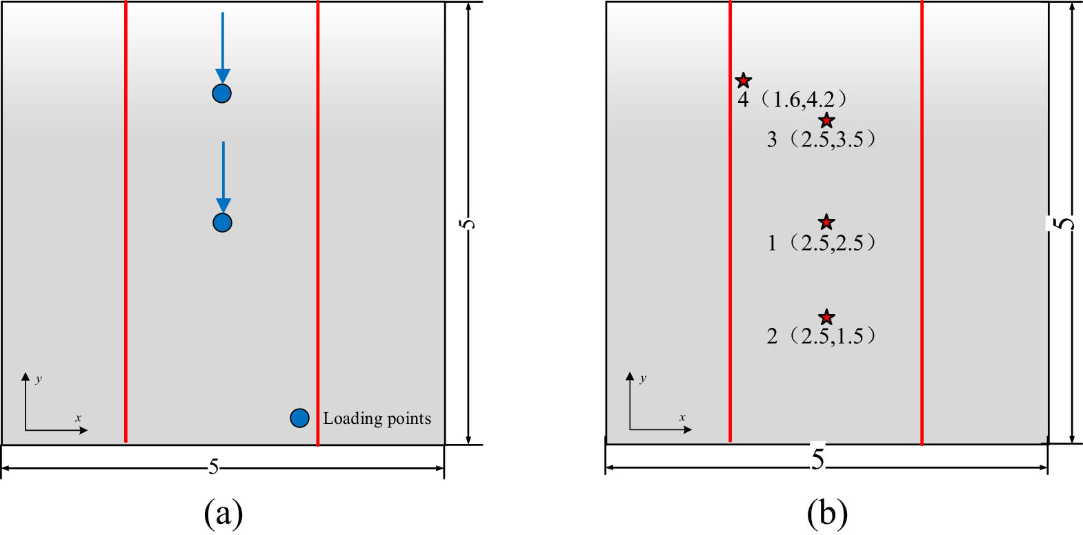
Schematic diagram of loading points and assessment nodes of the plate frame structure: (a) loading point and (b) assessment points.
The loading points displayed in Figure 2(a) are, respectively, geometric center (2.5,2.5) and (2.5,3.5) of the stiffened plate, and the assessment points are displayed in Figure 2(b).
The first three natural frequencies of the stiffened plate under clamped boundary conditions are shown in Table 1.
Natural frequencies of the grillage structure (Hz)
| Modal order | First | Second | Third |
|---|---|---|---|
| Grillage | 9.3 | 17.4 | 19.8 |
Under the action of a unit force at the loading points shown in Figure 2(a), the vibration displacement curve of assessment points in Figure 2(b) is shown in Figure 3.

Frequency–response curves of typical assessment points: (a) assessment point 1 (2.5,2.5), (b) assessment point 2 (2.5,1.5), (c) assessment point 3 (2.5,3.5) and (d) assessment point 4 (1.6,4.2).
It can be seen from Figure 3 that the peak corresponds to 19.8 Hz (the third-order natural frequency) does not appear in the frequency–response curve of assessment point 1. Analysis suggests that the reason is point 1 is located at the node of the third-order vibration mode. Compared with assessment point 1, the new peak generates at the third-order natural frequency of 19.8 Hz in the vibration curve of assessment point 2. The vibration–response curve of assessment points 3 and 4 is almost the same as assessment point 2.
As displayed in Figure 3, the maximum and second-order resonance peaks of typical assessment points, respectively, appear at the first-order 9.3 Hz and the third-order 19.8 Hz. Therefore, the first- and third-order modes of the stiffened plate will be chosen as the control object in the subsequent design of the low-frequency multiline spectrum distributed by the dynamic vibration absorption device.
First, the equivalent modal mass [46] to be controlled at the position of the dynamic vibration absorption of the stiffened plate is solved by equation (11):
In equation (11),
According to the calculation, the corresponding equivalent mass at the antinode of the first-order mode of the stiffened plate is 898.8 kg, and the corresponding equivalent mass at the antinode of the third-order mode is 988.2 kg. The optimal frequency ratio and damping parameters are, respectively displayed, in equations (9) and (10). When the mass ratio is set as 0.02, the parameters of the dynamic vibration absorption can be obtained by referring to the above formula.
The dynamic vibration absorption devices are set as the parameters in Table 2 and installed at the antinode of the first- and third-order vibration mode of the stiffened plate, respectively. The layout position of dynamic vibration absorption and the schematic diagram of assessment points are separately shown in Figure 4(a) and (b):
Parameter table of dynamic vibration absorbers for plate structures
| Parametert | Mass ratio | Mass (kg) | Spring stiffness (N·m−1) | Damping coefficient (N·s·m−1) |
|---|---|---|---|---|
| First order | 0.02 | 18.0 | 61557.4 | 180.4 |
| Third order | 0.02 | 19.8 | 294662.4 | 413.9 |
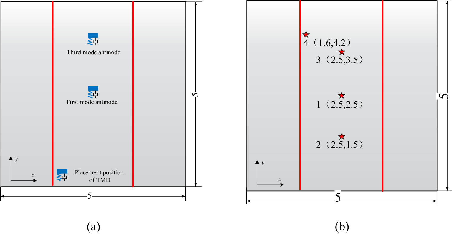
Schematic diagram of assessment points and the placement position of the dynamic vibration absorption of the plate frame structure: (a) placement position of the dynamic vibration absorber and (b) location of the assessment point.
The comparison of vibration–response curves of typical assessment points in Figure 4(b) before and after the installation of dynamic vibration absorber are demonstrated in Figure 5.

Comparison of frequency–response curves of typical assessment points: (a) assessment point 1 (2.5,2.5), (b) assessment point 2 (2.5,1.5), (c) assessment point 3 (2.5,3.5), and (d) assessment point 4 (1.6,4.2).
The Figure 5 displays the comparison of frequency-response curves of typical points based on the optimal homology design method. When the mass ratio of the dynamic vibration absorption device is set to 0.02, the first- and third-order resonance peak of each assessment point decreases more than 27 and 25 dB, which verifies the effective control of the low-frequency multiline spectrum of the stiffened plate. In addition, the vibration absorption effect decreases with the increase of the distance between the assessment point and the installation position of the dynamic vibration absorption.
3.2 Low-frequency multi-line spectrum vibration control method of offshore platforms
In the previous section, we analyzed the distributed dynamic vibration absorption of the stiffened plate under multipoint excitation. On the basis of this, the research on the low-frequency multiline spectrum vibration control method of platforms will be carried out in this section. The control process is shown in Figure 6.

Low-frequency multiline spectrum vibration control process of the offshore platform.
It can be seen from Figure 6 that the low-frequency multiline spectrum vibration control method of the offshore platform mainly includes the following parts: (1) Establishment of an equivalent numerical model of the local resonance area to be controlled. (2) The solution of equivalent mass and parameters of dynamic vibration absorption device. (3) Verification of dynamic vibration absorption effect. The specific process is given in the following sections.
3.2.1 Equivalent numerical model of the local resonance area
By means of combining the finite element cloud diagram and frequency–response curve of the assessment points, the local resonance region can be determined. Then, the free vibration of the local resonance region can be calculated. Finally, the boundary conditions of the equivalent numerical model of the local resonance region can be determined by comparing with the frequency–response curve.
3.2.2 Parameter design of the dynamic vibration absorber
Based on the vibration mode of the equivalent numerical model of the local resonance area, the vicinity of the antinode of the mode to be controlled is selected as the installation position of the dynamic vibration absorption device. Further, the equivalent mass of the mode to be controlled at the installation position of the dynamic vibration absorption is determined based on formula (11). In addition, the parameters of the dynamic vibration absorption device are determined by combining the optimal homology equations (9) and (10).
3.2.3 Verification and analysis of the vibration absorption effect
Finally, the effect of the dynamic vibration absorption device is verified on the basis of the finite element method.
3.3 Verification of the low-frequency multiline spectral vibration control of the offshore platform
A large offshore platform is chosen as the research object in this section, and the low-frequency multiline spectrum vibration of the local resonance area of the offshore platform has been controlled on the basis of the research mentioned above.
3.3.1 Dynamic analysis model and the load of the platform
As a complex structure, when analyzing its dynamic characteristics, it is necessary to reasonably simplify the offshore platform, equipment and flow field. In addition, it is necessary to select the appropriate size of the mesh to divide the model. During the meshing process, the longitudinal and transverse spacings of the grid shall not be greater than the strong frame spacing and longitudinal truss spacing, respectively. Taking into account the solution accuracy and efficiency, the finite element scale is finally determined to be 0.5 m. The final finite element model of the platform includes 340,904 surface elements and 140,900 beam elements.
Six main engines are arranged on the platform, with a power of 4,950 kW. The speed of the main engine is 720 rpm and the weight of each main engine is 84 t. The vibration acceleration of the main engine tested on the ship is displayed in Figure 7, which is applied vertically to the mass point above the base corresponding to the main engines.

Main engine load of the semi-submersible support platform.
3.3.2 Platform vibration response
Based on the finite element model superposition method, the vibration response of the platform is analyzed. The partial response cloud plot of the superstructure cab at frequencies of 12 and 19 Hz are, respectively, shown in Figure 8(a) and (b). It is clear that the vibration response cloud of the superstructure cab at frequencies of 12 and 19 Hz are, respectively, well consistent with the first- and fourth-order vibration mode of the local resonance area.

Vibration response of the superstructure cab: (a) 12 Hz and (b) 19 Hz.
The assessment points of #7–#10 displayed in Figure 8 are chosen as the typical assessment points, and the vibration–response curves of the assessment points are displayed in Figure 9.
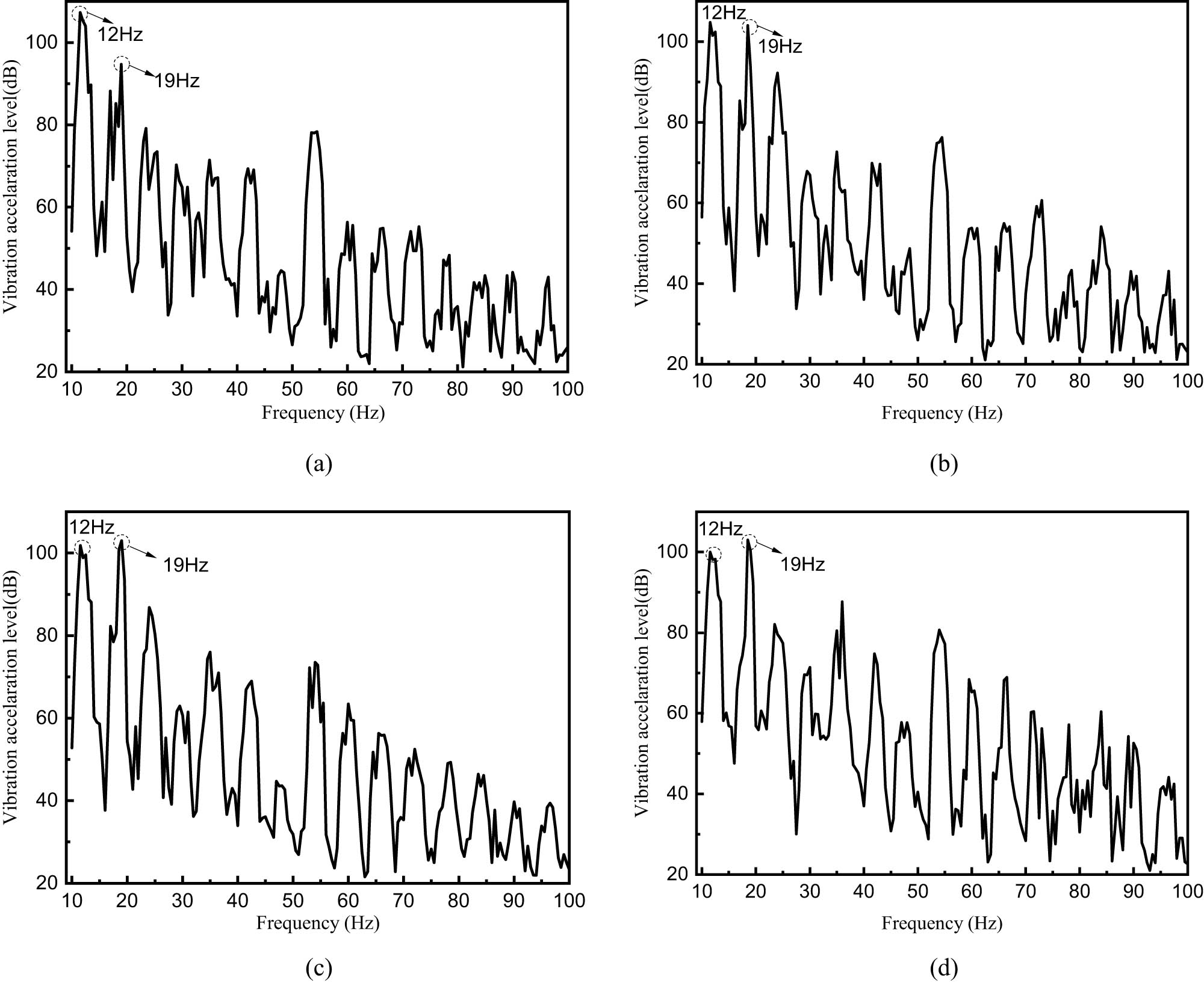
Vibration–response curves of typical nodes of the superstructure cab: (a) assessment point #7, (b) assessment point #8, (c) assessment point #9 and (d) assessment point #10.
Assessment points #7 and #8 are both located near the antinode of the first-order vibration mode of the superstructure cab. The response of assessment points #7 at 12 Hz is greater than 19 Hz, and the response of assessment points #8 at 12 Hz and 19 Hz is similar. In addition, assessment points #9 and #10 are located near the antinode of the vibration mode corresponding to 19 Hz. Therefore, the response of the above assessment points #9 and #10 at 19 Hz is slightly greater than 12 Hz. It follows that the amplitude of the vibration–response curve of the assessment point is determined by the location of assessment points and load characteristics.
3.3.3 Dynamic vibration absorption design in the local resonance region
According to the flow in Figure 6, the low-frequency multiline spectrum vibration control of the superstructure cab has been conducted. Depending on the vibration response nephogram of the superstructure cab and the bulkhead partition, the local resonance region is partitioned. When the boundary condition is set as simply supported, the vibration modes of the local resonance region at corresponding frequencies are basically consistent with the overall finite element calculation results of the platform.
The antinodes of 12 and 19 Hz modal shapes in the local resonance area of the superstructure cab are, respectively, selected as the installation position of the dynamic vibration absorption. According to equation (11), the equivalent mass of the 12 and 19 Hz mode antinodes are 7348.5 and 4026.7 kg, respectively. When the mass ratio is set as 0.02, the parameters of dynamic vibration absorption are as listed in Table 3.
Equivalent mass of the cab truncation model and parameters of dynamic vibration absorption devices
| Parameter | Mass ratio | Mass (kg) | Spring stiffness (N·m−1) | Damping coefficient (N·s·m−1) |
|---|---|---|---|---|
| First order | 0.02 | 147.0 | 819126.1 | 1891.0 |
| Fourth order | 0.02 | 80.5 | 1125242.3 | 1640.6 |
When the dynamic vibration absorption devices are arranged at antinodes of 12 and 19 Hz modes, respectively. The cloud diagram of the vibration response before and after the dynamic vibration absorber is arranged as shown in Figure 10:

Comparison of the cloud chart of the vibration acceleration response before and after distributed dynamic vibration absorption of the cab deck. (a) Comparison of nephograms before and after dynamic vibration absorption layout of 12 Hz. (b) Comparison of nephograms before and after dynamic vibration absorption layout of 19 Hz.
It is easy to find that under the combined action of the distributed dynamic vibration absorber, the vibration response of the driving deck at 12 and 19 Hz is significantly reduced. Meanwhile, the corresponding comparison of vibration acceleration response curves of typical assessment points is listed in Figure 11.

Vibration response of typical nodes of the superstructure cab before and after optimization of typical examination points of the upper cab: (a) assessment point #7, (b) assessment point #8, (c) assessment point #9 and (d) assessment point #10.
To sum up, by combining the low-frequency multiline spectrum vibration control method of the platform with the finite element method, the low-frequency multiline spectrum vibration of the local resonance region of the platform is effectively controlled. The vibration acceleration of typical assessment points at 12 and 19 Hz decreased by more than 13 dB.
4 Conclusion
In the current research, by means of combining the low-frequency multiline spectrum vibration control process and modal superposition method, the low-frequency multiline spectrum distributed dynamic vibration absorption method of the platform is proposed.
First, the current research status of the vibration control methods of offshore platforms is briefly introduced. Then, we give a brief introduction to the theoretical basis of dynamic vibration absorption. Afterward, a stiffened plate under clamped boundary conditions is chosen as the research object to investigate the effect of distributed dynamic vibration absorption devices. Finally, the low-frequency multiline spectrum vibration control process of the offshore platform is proposed. The effectiveness of the proposed method is also verified in the calculation of the platform. The conclusions of the current research are as follows:
The amplitude of the vibration–response curve of the assessment point is determined by the location of the assessment point and load characteristics.
When the dynamic vibration absorption mass ratio is set as 0.02, the vibration acceleration response curve at signature frequencies (12 and 19 Hz) decreases by more than 13 dB under the action of distributed dynamic vibration absorption.
By means of combining the low-frequency multiline spectrum vibration control method with the finite element method, the multiline spectrum vibration in the local resonance region of the offshore platform is controlled effectively and quickly.
Acknowledgements
I would like to express my gratitude to all editors who helped me during the writing of this thesis.
-
Funding information: This study was funded by the National Natural Science Foundation of China (52101351, U2006229), the National Key Research and Development Program (2016YFC0303406), and the Key Research and Development Program of Shandong Province (2019JZZY010125, 2020CXGC010701, 2020CXGC010702).
-
Author contributions: Yuan Du, Qingtao Gong contributed to the conception of the study. Na Wang, Ning Liu, Yao Teng performed the data analyses and wrote the manuscript.
-
Conflict of interest: The authors declare that they have no conflict of interest.
-
Data availability statement: The data used to support the findings of this study are included within the article.
References
[1] Asiri, S. A. and Y. Z. AL-Zahrani. Theoretical analysis of mechanical vibration for offshore platform structures. World Journal of Mechanics, Vol. 4, No. 1, 2014, pp. 1–11.10.4236/wjm.2014.41001Search in Google Scholar
[2] Zhang, B.-L., Q.-L. Han, and X.-M. Zhang. Recent advances in vibration control of offshore platforms. Nonlinear Dynamics, Vol. 89, No. 2, 2017, pp. 755–771.10.1007/s11071-017-3503-4Search in Google Scholar
[3] Liu, Y., Z. Lu, X. Yan, Z. Liu, and L. Tang. Measurement and modelling of the vibration induced by working equipment on an offshore platform. Ocean Engineering, Vol. 219, 2021, id. 108354.10.1016/j.oceaneng.2020.108354Search in Google Scholar
[4] Som, A. and D. Das. Seismic vibration control of offshore jacket platforms using decentralized sliding mode algorithm. Ocean Engineering, Vol. 152, 2018, pp. 377–390.10.1016/j.oceaneng.2018.01.013Search in Google Scholar
[5] Kandasamy, R., F. Cui, N. Townsend, C. C. Foo, J. Guo, A. Shenoi, et al. A review of vibration control methods for marine offshore structures. Ocean Engineering, Vol. 127, 2016, pp. 279–297.10.1016/j.oceaneng.2016.10.001Search in Google Scholar
[6] Zhang, B., Q. Han, X. Zhang, and G. Tang. Active control of offshore steel jacket platforms, Springer, Singapore, 2019.10.1007/978-981-13-2986-9Search in Google Scholar
[7] Sarkar, S. and B. Fitzgerald. Vibration control of spar-type floating offshore wind turbine towers using a tuned mass-damper-inerter. Structural Control and Health Monitoring, Vol. 27, No. 1, 2020, id. e2471.10.1002/stc.2471Search in Google Scholar
[8] Xu, Z.-D., F.-H. Xu, and X. Chen. Vibration suppression on a platform by using vibration isolation and mitigation devices. Nonlinear Dynamics, Vol. 83, No. 3, 2016, pp. 1341–1353.10.1007/s11071-015-2407-4Search in Google Scholar
[9] Wang, S., Q. Yue, and D. Zhang. Ice-induced non-structure vibration reduction of jacket platforms with isolation cone system. Ocean Engineering, Vol. 70, 2013, pp. 118–123.10.1016/j.oceaneng.2013.05.018Search in Google Scholar
[10] Xu, Z. D., X. H. Huang, F. H. Xu, and J. Yuan. Parameters optimization of vibration isolation and mitigation system for precision platforms using non-dominated sorting genetic algorithm. Mechanical Systems and Signal Processing, Vol. 128, 2019, pp. 191–201.10.1016/j.ymssp.2019.03.031Search in Google Scholar
[11] Ma, R., K. Bi, and H. Hao. Heave motion mitigation of semi-submersible platform using inerter-based vibration isolation system (IVIS). Engineering Structures, Vol. 219, 2020, id. 110833.10.1016/j.engstruct.2020.110833Search in Google Scholar
[12] Golafshani, A. A. and A. Gholizad. Friction damper for vibration control in offshore steel jacket platforms. Journal of Constructional Steel Research, Vol. 65, No. 1, 2009, pp. 180–187.10.1016/j.jcsr.2008.07.008Search in Google Scholar
[13] Patil, K. and R. Jangid. Passive control of offshore jacket platforms. Ocean Engineering, Vol. 32, No. 16, 2005, pp. 1933–1949.10.1016/j.oceaneng.2005.01.002Search in Google Scholar
[14] Minh Le, L., D. Van Nguyen, S. Chang, D. Kim, S. G. Cho, and D. D. Nguyen. Vibration control of jacket offshore wind turbine subjected to earthquake excitations by using friction damper. Journal of Structural Integrity and Maintenance, Vol. 4, No. 1, 2019, pp. 1–5.10.1080/24705314.2019.1565055Search in Google Scholar
[15] Enferadi, M. H., M. R. Ghasemi, and N. Shabakhty. Wave-induced vibration control of offshore jacket platforms through SMA dampers. Applied Ocean Research, Vol. 90, 2019, id. 101848.10.1016/j.apor.2019.06.005Search in Google Scholar
[16] Zhang, X., B. H. Tan, and Z. Li. Seismic performance and ice-induced vibration control of offshore platform structures based on the ISO-PFD-SMA brace system. Advances in Materials Science and Engineering, Vol. 92, 2017, pp. 1061–1074.10.1155/2017/3596094Search in Google Scholar
[17] Sellitto, A. and A. Riccio. Overview and future advanced engineering applications for morphing surfaces by shape memory alloy materials. Materials, Vol. 12, No. 5, 2019, id. 708.10.3390/ma12050708Search in Google Scholar PubMed PubMed Central
[18] Choi, E., B. Mohammadzadeh, J. H. Hwang, and J. H. Lee. Displacement-recovery-capacity of superelastic SMA fibers reinforced cementitious materials. Smart Structures and Systems, Vol. 24, No. 2, 2019, pp. 157–171.Search in Google Scholar
[19] Levintant-Zayonts, N., G. Starzynski, M. Kopec, and S. Kucharski. Characterization of NiTi SMA in its unusual behaviour in wear tests. Tribology International, Vol. 137, 2019, pp. 313–323.10.1016/j.triboint.2019.05.005Search in Google Scholar
[20] Dutta, S. C. and R. Majumder. Shape memory alloy (SMA) as a potential damper in structural vibration control. Advances in Manufacturing Engineering and Materials, Springer, Cham, 2019, 485–492.10.1007/978-3-319-99353-9_51Search in Google Scholar
[21] Kamarian, S., M. Bodaghi, R. B. Isfahani, and J. Song. A comparison between the effects of shape memory alloys and carbon nanotubes on the thermal buckling of laminated composite beams. Mechanics Based Design of Structures and Machines, 2020, pp. 1–24. 10.1080/15397734.2020.1776131.Search in Google Scholar
[22] Sheikhi, J., M. Fathi, R. Rahnavard, and R. Napolitano. Numerical analysis of natural rubber bearing equipped with steel and shape memory alloys dampers. Structures, Elsevier, Vol. 32, 2021, pp. 1839–1855.10.1016/j.istruc.2021.03.115Search in Google Scholar
[23] Li, H., F. Pang, X. Wang, Y. Du, and H. Chen. Free vibration analysis for composite laminated doubly-curved shells of revolution by a semi analytical method. Composite Structures, Vol. 201, 2018, pp. 86–111.10.1016/j.compstruct.2018.05.143Search in Google Scholar
[24] Li, H., F. Pang, H. Chen, and Y. Du. Vibration analysis of functionally graded porous cylindrical shell with arbitrary boundary restraints by using a semi analytical method. Composites, Part B: Engineering, Vol. 164, 2019, pp. 249–264.10.1016/j.compositesb.2018.11.046Search in Google Scholar
[25] Li, H., F. Pang, Q. Gong, and Y. Teng. Free vibration analysis of axisymmetric functionally graded doubly-curved shells with un-uniform thickness distribution based on Ritz method. Composite Structures, Vol. 225, 2019, id. 111145.10.1016/j.compstruct.2019.111145Search in Google Scholar
[26] Li, H., F. Pang, Y. Li, and C. Gao. Application of first-order shear deformation theory for the vibration analysis of functionally graded doubly-curved shells of revolution. Composite Structures, Vol. 212, 2019, pp. 22–42.10.1016/j.compstruct.2019.01.012Search in Google Scholar
[27] Li, H., F. Pang, X. Miao, S. Gao, and F. Liu. A semi analytical method for free vibration analysis of composite laminated cylindrical and spherical shells with complex boundary conditions. Thin-Walled Structures, Vol. 136, 2019, pp. 200–220.10.1016/j.tws.2018.12.009Search in Google Scholar
[28] Ghasemi, M. R., N. Shabakhty, and M. H. Enferadi. Vibration control of offshore jacket platforms through shape memory alloy pounding tuned mass damper (SMA-PTMD). Ocean Engineering, Vol. 191, 2019, id. 106348.10.1016/j.oceaneng.2019.106348Search in Google Scholar
[29] Konar, T. and A. D. Ghosh. Flow damping devices in tuned liquid damper for structural vibration control: a review. Archives of Computational Methods in Engineering, Vol. 28, 2021, pp. 2195–2207.10.1007/s11831-020-09450-0Search in Google Scholar
[30] Zhang, Z., A. Staino, B. Basu, and S. R. K. Nielsen. Performance evaluation of full-scale tuned liquid dampers (TLDs) for vibration control of large wind turbines using real-time hybrid testing. Engineering Structures, Vol. 126, 2016, pp. 417–431.10.1016/j.engstruct.2016.07.008Search in Google Scholar
[31] Jahangiri, V. and C. Sun. Three-dimensional vibration control of offshore floating wind turbines using multiple tuned mass dampers. Ocean Engineering, Vol. 206, 2020, id. 107196.10.1016/j.oceaneng.2020.107196Search in Google Scholar
[32] Yang, J. and E. He. Coupled modeling and structural vibration control for floating offshore wind turbine. Renewable Energy, Vol. 157, 2020, pp. 678–694.10.1016/j.renene.2020.05.075Search in Google Scholar
[33] Yang, J., E. He, and Y. Hu. Dynamic modeling and vibration suppression for an offshore wind turbine with a tuned mass damper in floating platform. Applied Ocean Research, Vol. 83, 2019, pp. 21–29.10.1016/j.apor.2018.08.021Search in Google Scholar
[34] Hussan, M., M. S. Rahman, F. Sharmin, D. Kim, and J. Do. Multiple tuned mass damper for multi-mode vibration reduction of offshore wind turbine under seismic excitation. Ocean Engineering, Vol. 160, 2018, pp. 449–460.10.1016/j.oceaneng.2018.04.041Search in Google Scholar
[35] Vandiver, J. K. and S. Mitome. Effect of liquid storage tanks on the dynamic response of offshore platforms. Applied Ocean Research, Vol. 1, No. 2, 1979, pp. 67–74.10.4043/3162-MSSearch in Google Scholar
[36] Lee, H. H., S. H. Wong, and R. S. Lee. Response mitigation on the offshore floating platform system with tuned liquid column damper. Ocean Engineering, Vol. 33, No. 8, 2006, pp. 1118–1142.10.1016/j.oceaneng.2005.06.008Search in Google Scholar
[37] Jin, Q., X. Li, N. Sun, J. Zhou, and J. Guan. Experimental and numerical study on tuned liquid dampers for controlling earthquake response of jacket offshore platform. Marine Structures, Vol. 20, No. 4, 2007, pp. 238–254.10.1016/j.marstruc.2007.05.002Search in Google Scholar
[38] Lotfollahi-Yaghin, M. A., H. Ahmadi, and H. Tafakhor. Seismic responses of an offshore jacket-type platform incorporated with tuned liquid dampers. Advances in Structural Engineering, Vol. 19, No. 2, 2016, pp. 227–238.10.1177/1369433215624340Search in Google Scholar
[39] Yue, Q., L. Zhang, W. Zhang, and T. Kärnä. Mitigating ice-induced jacket platform vibrations utilizing a TMD system. Cold Regions Science Technology, Vol. 56, No. 2–3, 2009, pp. 84–89.10.1016/j.coldregions.2008.11.005Search in Google Scholar
[40] Taflanidis, A. A., D. C. Angelides, and J. T. Scruggs. Simulation-based robust design of mass dampers for response mitigation of tension leg platforms. Engineering Structures, Vol. 31, No. 4, 2009, pp. 847–857.10.1016/j.engstruct.2008.11.014Search in Google Scholar
[41] Chandrasekaran, S., D. Kumar, and R. Ramanathan. Dynamic response of tension leg platform with tuned mass dampers. Journal of Naval Architecture Marine Engineering, Vol. 10, No. 2, 2013, pp. 149–156.10.3329/jname.v10i2.16184Search in Google Scholar
[42] Deng, W., J. Xu, X.-Z. Gao, and H. Zhao. An enhanced MSIQDE algorithm with novel multiple strategies for global optimization problems. IEEE Transactions on Systems, Man, and Cybernetics: Systems, Vol. 52, No. 3, 2022, pp. 1578–1587.10.1109/TSMC.2020.3030792Search in Google Scholar
[43] Deng, W., S. Shang, X. Cai, H. Zhao, Y. Song, and J. Xu. An improved differential evolution algorithm and its application in optimization problem. Soft Computing, Vol. 25, No. 7, 2021, pp. 5277–5298.10.1007/s00500-020-05527-xSearch in Google Scholar
[44] Deng, W., S. Shang, X. Cai, H. Zhao, Y. Zhou, H. Chen, et al. Quantum differential evolution with cooperative coevolution framework and hybrid mutation strategy for large scale optimization. Knowledge-Based Systems, Vol. 224, 2021, id. 107080.10.1016/j.knosys.2021.107080Search in Google Scholar
[45] Zhao, H., H. Liu, Y. Jin, X. Dang, and W. Deng. Feature extraction for data-driven remaining useful life prediction of rolling bearings. IEEE Transactions on Instrumentation and Measurement, Vol. 70, 2021, pp. 1–10.10.1109/TIM.2021.3059500Search in Google Scholar
[46] Den Hartog, J. P. Mechanical vibrations, 4th edn. Dover, New York, 1985.Search in Google Scholar
© 2022 Na Wang et al., published by De Gruyter
This work is licensed under the Creative Commons Attribution 4.0 International License.
Articles in the same Issue
- Review Articles
- State of the art, challenges, and emerging trends: Geopolymer composite reinforced by dispersed steel fibers
- A review on the properties of concrete reinforced with recycled steel fiber from waste tires
- Copper ternary oxides as photocathodes for solar-driven CO2 reduction
- Properties of fresh and hardened self-compacting concrete incorporating rice husk ash: A review
- Basic mechanical and fatigue properties of rubber materials and components for railway vehicles: A literature survey
- Research progress on durability of marine concrete under the combined action of Cl− erosion, carbonation, and dry–wet cycles
- Delivery systems in nanocosmeceuticals
- Study on the preparation process and sintering performance of doped nano-silver paste
- Analysis of the interactions between nonoxide reinforcements and Al–Si–Cu–Mg matrices
- Research Articles
- Study on the influence of structural form and parameters on vibration characteristics of typical ship structures
- Deterioration characteristics of recycled aggregate concrete subjected to coupling effect with salt and frost
- Novel approach to improve shale stability using super-amphiphobic nanoscale materials in water-based drilling fluids and its field application
- Research on the low-frequency multiline spectrum vibration control of offshore platforms
- Multiple wide band gaps in a convex-like holey phononic crystal strip
- Response analysis and optimization of the air spring with epistemic uncertainties
- Molecular dynamics of C–S–H production in graphene oxide environment
- Residual stress relief mechanisms of 2219 Al–Cu alloy by thermal stress relief method
- Characteristics and microstructures of the GFRP waste powder/GGBS-based geopolymer paste and concrete
- Development and performance evaluation of a novel environmentally friendly adsorbent for waste water-based drilling fluids
- Determination of shear stresses in the measurement area of a modified wood sample
- Influence of ettringite on the crack self-repairing of cement-based materials in a hydraulic environment
- Multiple load recognition and fatigue assessment on longitudinal stop of railway freight car
- Synthesis and characterization of nano-SiO2@octadecylbisimidazoline quaternary ammonium salt used as acidizing corrosion inhibitor
- Perforated steel for realizing extraordinary ductility under compression: Testing and finite element modeling
- The influence of oiled fiber, freeze-thawing cycle, and sulfate attack on strain hardening cement-based composites
- Perforated steel block of realizing large ductility under compression: Parametric study and stress–strain modeling
- Study on dynamic viscoelastic constitutive model of nonwater reacted polyurethane grouting materials based on DMA
- Mechanical behavior and mechanism investigation on the optimized and novel bio-inspired nonpneumatic composite tires
- Effect of cooling rate on the microstructure and thermal expansion properties of Al–Mn–Fe alloy
- Research on process optimization and rapid prediction method of thermal vibration stress relief for 2219 aluminum alloy rings
- Failure prevention of seafloor composite pipelines using enhanced strain-based design
- Deterioration of concrete under the coupling action of freeze–thaw cycles and salt solution erosion
- Creep rupture behavior of 2.25Cr1Mo0.25V steel and weld for hydrogenation reactors under different stress levels
- Statistical damage constitutive model for the two-component foaming polymer grouting material
- Nano-structural and nano-constraint behavior of mortar containing silica aggregates
- Influence of recycled clay brick aggregate on the mechanical properties of concrete
- Effect of LDH on the dissolution and adsorption behaviors of sulfate in Portland cement early hydration process
- Comparison of properties of colorless and transparent polyimide films using various diamine monomers
- Study in the parameter influence on underwater acoustic radiation characteristics of cylindrical shells
- Experimental study on basic mechanical properties of recycled steel fiber reinforced concrete
- Dynamic characteristic analysis of acoustic black hole in typical raft structure
- A semi-analytical method for dynamic analysis of a rectangular plate with general boundary conditions based on FSDT
- Research on modification of mechanical properties of recycled aggregate concrete by replacing sand with graphite tailings
- Dynamic response of Voronoi structures with gradient perpendicular to the impact direction
- Deposition mechanisms and characteristics of nano-modified multimodal Cr3C2–NiCr coatings sprayed by HVOF
- Effect of excitation type on vibration characteristics of typical ship grillage structure
- Study on the nanoscale mechanical properties of graphene oxide–enhanced shear resisting cement
- Experimental investigation on static compressive toughness of steel fiber rubber concrete
- Study on the stress field concentration at the tip of elliptical cracks
- Corrosion resistance of 6061-T6 aluminium alloy and its feasibility of near-surface reinforcements in concrete structure
- Effect of the synthesis method on the MnCo2O4 towards the photocatalytic production of H2
- Experimental study of the shear strength criterion of rock structural plane based on three-dimensional surface description
- Evaluation of wear and corrosion properties of FSWed aluminum alloy plates of AA2020-T4 with heat treatment under different aging periods
- Thermal–mechanical coupling deformation difference analysis for the flexspline of a harmonic drive
- Frost resistance of fiber-reinforced self-compacting recycled concrete
- High-temperature treated TiO2 modified with 3-aminopropyltriethoxysilane as photoactive nanomaterials
- Effect of nano Al2O3 particles on the mechanical and wear properties of Al/Al2O3 composites manufactured via ARB
- Co3O4 nanoparticles embedded in electrospun carbon nanofibers as free-standing nanocomposite electrodes as highly sensitive enzyme-free glucose biosensors
- Effect of freeze–thaw cycles on deformation properties of deep foundation pit supported by pile-anchor in Harbin
- Temperature-porosity-dependent elastic modulus model for metallic materials
- Effect of diffusion on interfacial properties of polyurethane-modified asphalt–aggregate using molecular dynamic simulation
- Experimental study on comprehensive improvement of shear strength and erosion resistance of yellow mud in Qiang Village
- A novel method for low-cost and rapid preparation of nanoporous phenolic aerogels and its performance regulation mechanism
- In situ bow reduction during sublimation growth of cubic silicon carbide
- Adhesion behaviour of 3D printed polyamide–carbon fibre composite filament
- An experimental investigation and machine learning-based prediction for seismic performance of steel tubular column filled with recycled aggregate concrete
- Effects of rare earth metals on microstructure, mechanical properties, and pitting corrosion of 27% Cr hyper duplex stainless steel
- Application research of acoustic black hole in floating raft vibration isolation system
- Multi-objective parametric optimization on the EDM machining of hybrid SiCp/Grp/aluminum nanocomposites using Non-dominating Sorting Genetic Algorithm (NSGA-II): Fabrication and microstructural characterizations
- Estimating of cutting force and surface roughness in turning of GFRP composites with different orientation angles using artificial neural network
- Displacement recovery and energy dissipation of crimped NiTi SMA fibers during cyclic pullout tests