Recent developments in ultrasonic welding of similar and dissimilar joints of carbon fiber reinforcement thermoplastics with and without interlayer: A state-of-the-art review
-
Zummurd Al Mahmoud
 ,
Rosli Ahmad
,
Rosli Ahmad

Abstract
Ultrasonic welding (USW) is utilized to join identical and non-identical materials, with and without a thermoplastic composites or thermoset composites coupling layer, or with different shapes of energy directors or adhesive materials. Due to its emerging structure, joining carbon fiber (CF)-reinforced polymer has become imperative due to the developed concerns in different industrial and manufacturing sectors. This review article covers all types of joined CF-reinforced polymers, including similar/dissimilar CF-reinforced thermoplastics or CF-reinforced thermosets joined by USW, considering different types of USW (spot welding, continuous welding). This review considers various welding process parameters and their impacts on welding quality, welding strength, and mechanical and microstructure characterizations of the welded joint. Also, improving the USW joints and their challenges are discussed. The fabrication processes of the polymer matrix composite and various polymers are addressed. In addition, the recyclability of CF-reinforced polymer is highlighted. A key finding from this review is that polyetheretherketone and both types of nylon (PA6 and PA66) show high exceptional characterizations, making them more favorable for developing CF-reinforced thermoplastics over other types of polymers. While a unique co-curing process must be completed for the adhesive material before performing the USW, welding energy is the most effective process parameter that enhances the mechanical properties when using adhesive bonding before USW.
Abbreviations
- AM
-
additive manufacturing
- AF
-
aramid fiber
- BO
-
Bayesian optimization
- CF
-
carbon fiber
- CFRP
-
carbon fiber-reinforced polymer
- CFRTP
-
carbon fiber-reinforced thermoplastic
- CFRTSC
-
carbon fiber-reinforced thermoplastic composite
- CFRTS
-
carbon fiber-reinforced thermoset
- CF/Ep
-
carbon fiber/epoxy
- CNT
-
carbon nanotube
- CUSW
-
conventional ultrasonic welding
- CTT
-
cross tensile test
- DSW
-
double spot welding
- DLS
-
double-lap shear
- ELF
-
Elium® film
- ELP
-
Elium® particle
- ED
-
energy director
- EMMA
-
mendable polymer, poly [ethylene-co-(methacrylic acid)]
- Ep
-
epoxy
- FRC
-
fiber-reinforced composites
- FRTP
-
fiber-reinforced thermoplastic
- FRP
-
fiber-reinforced polymer
- FE
-
finite element
- FED
-
flat energy director
- FSW
-
friction stir welding
- GA
-
genetic algorithm
- GF
-
glass fiber
- GFRP
-
glass fiber-reinforced polymer
- GNP
-
graphite nanoplatelet
- HAZ
-
heat-affected zone
- HHT
-
Hilbert-Huang transform
- HFUSW
-
hollow fixture ultrasonic welding
- HNT
-
halloysite nanotube
- IPS
-
interposed sheet
- IW
-
induction welding
- LSS
-
lap shear strength
- LW
-
laser welding
- ML
-
machine learning
- MF
-
mechanical fastener
- MSW
-
multi-spot welding
- MWCNT
-
multi-walled CNT
- NC
-
nanocomposite
- NF
-
nanofiller
- NFRC
-
natural fiber-reinforced composite
- NSM
-
near-surface mounted
- NN
-
neural network
- NL
-
nonlinear
- PBF
-
powder bed fusion
- PC
-
polycarbonate
- PEI
-
polyetherimide
- PFRP
-
polymer fiber-reinforced polymer
- PMC
-
polymer matrix composite
- PCM
-
polymer-coated material
- PMMA
-
polymethyl methacrylate polymer
- POF
-
plastic optical fiber
- PVA
-
polyvinyl alcohol
- PVB
-
polyvinyl butyral
- rCF
-
recycled carbon fiber
- RF
-
reed flour
- RTM
-
resin transfer molding
- RW
-
resistance welding
- SSW
-
single spot welding
- SE
-
steam-exploded
- S-USW
-
water-submerged ultrasonic welding
- SVM
-
support vector machine
- TOF
-
Time-of-flight
- TPC
-
thermoplastic composite
- TP
-
thermoplastic
- TSC
-
thermoset composite
- UF
-
ultimate failure
- UFL
-
ultimate failure load
- USW
-
ultrasonic welding
- VaRTM
-
vacuum-assisted resin transfer molding
- VMD
-
variational mode decomposition
- 2D
-
two-dimensional
1 Introduction
1.1 Ultrasonic application and ultrasonic welding (USW) for polymers
USW is a speedy process of joining materials. It can be used for joining alloy/composites and composite/composite. USW is considered as a solid-state welding method that is defined as a sustainable welding process [1]. It is worth mentioning that the USW is one of the most promising fusion bonding processes. Nonetheless, the fusion bonding technologies consist of USW, induction welding (IW), and resistance welding (RW) techniques [2]. The basic concept of USW is based on the ultrasonic wave, which is same as any other ultrasonic process machine (based on ultrasonic wave) applications. Figure 1 illustrates the current applications of various ultrasonic machines for polymer industries. As shown in Figure 1, the major applications of ultrasonic for polymers can be classified into four main categories, which are fabrication process, welding, defect detection, and cleaning. However, each classification can be further classified as shown.

Applications of ultrasonic in polymers.
Furthermore, the USW main principle is based on very high frequency usually 20 kHz, associated with very low amplitude at the joining surface interface of the adherends to be welded. In the USW process, the vibrations are converted to heat between the two joining surfaces, which melt the thermoplastic composites (TPCs) and enable the joining [3,4,5,6], where the vibration energy leads to a surface asperity deformation, which disperses into heat. In consequence, the heat melts the surface asperities, which then flow, expanding the interfacial area, which permits the molecules of the polymer chains to diffuse [7]. High amount of frequency in kHz in the oscillation of the USW to the stacked specimens, frictional heat will be generated by the plastic boundaries, which melt and form the joint [4]. A schematic representation of USW machine with its components is given in Figure 2. The generated frictional heat is caused by the transmission of the mechanical vibration, which helps in melting the TPCs causing them to flow, which will cause the interfacial bond between the two specimens to join. This heating mechanism is classified as surface friction as well as viscoelastic friction [8,9]. Mainly, the viscoelastic heating became governing when the temperature reached the glass transition temperature, is the reason of providing the absolute heating during welding process [8]. As shown in Figure 2, the USW machine consists of generator, transducer, booster, sonotrode, and fixture. The generator converts the electrical power to high electrical energy at 20–40 kHz. The transducer works as a converter, which alters the high frequency electrical pulses to a mechanical vibration. The amplitude of this mechanical vibration is further increased or decreased by the booster. In consequence, the mechanical oscillations are transferred to the specimens by the sonotrode. However, the specimens remain stable by the fixture on the anvil [10]. Besides, the welding process consists of a solidification phase, which is a consequence of the vibrational phase, in which the heat is generated. Further, the vibration energy is transfererred to the sontrode, which creates the welded zone by heating the surface [11].
![Figure 2
The schematic of USW [20].](/document/doi/10.1515/rams-2024-0077/asset/graphic/j_rams-2024-0077_fig_002.jpg)
The schematic of USW [20].
The USW has the potential for extensive applications, particularly in lightweight vehicle structures, owing to its good strength and stiffness [12,13], as well as in the marine industry [14]. The global market scale of USW technology is demonstrated in Figure 3 [15,16]. As shown in Figure 3, the applications of joining polymers by USW are much greater than those of metals. Besides, a substantial increase in the global market is observed, where in 2022, the market size reached 550–560 million US dollar, while it is estimated to reach 825–840 million US dollar in 2030. However, the first publication regarding USW of TPCs was recorded in 1989 published by Benatar and Gutowski [17], where the processing information was highlighted, and the obtained outcomes were significant. Nonetheless, the USW has many advantages, e.g., it is a time-saving method and an economical technique for joining polymer composites [18], and disadvantages, e.g., it is mainly used for welding small areas and it can be used under some conditions for welding larger areas [19]. Further advantages and drawbacks of USW are illustrated in Figure 4.
![Figure 3
The global market scale of USW technology: (a) The development of USW in polymers and metals and (b and c) the annual global market of USW in various application sectors [15,16].](/document/doi/10.1515/rams-2024-0077/asset/graphic/j_rams-2024-0077_fig_003.jpg)

The advantages and disadvantages of USW process.
From literature records, Sandeep and Natarajan [21] presented a review that focused on investigating the recent developed joining methodologies for carbon fiber (CF)-reinforced polymer (CFRP)/Al-joined hybrid structures. Liu et al. [22] presented a comprehensive review to examine the metal/fiber-reinforced thermoplastic (FRTP) joined by USW. Abbas et al. [23] explored the developments in USW of joining lightweight alloys. Furthermore, Pramanik et al. [24] studied the earlier available joining techniques that were utilized in joining CFRP/Al. Besides, Fan et al. [25] presented a review study focused on considering various joints joined by implementing the ultrasound vibration. The dissimilar joining of carbon fiber-reinforced thermoplastic (CFRTP) with metals by laser welding (LW) has been reviewed by Jiao et al. [26]. Additionally, Acherjee [27] reviewed the parameters, process monitoring, and quality attributes of laser transmission welding used for similar and dissimilar joining of polymer/polymer and polymer/metal. Moreover, Li and Palardy [28] reviewed the methodologies, which are currently used to monitor the damage caused by fiber-reinforced polymer (FRP) joints. However, Li et al. [29] accomplished a comprehensive review that focused on examining the mechanical features as well as the behavior of structural health monitoring of carbon nanotube (CNT)–FRP composites. An evaluation between different types of joining approaches used to join TPCs and thermoset composites (TSCs) was published earlier. As findings, the USW was found to be most suitable in some essential factors of joining performance, processing time, minimal surface preparation, in situ inspection production environment, and reproducibility [30]. However, a short review study has been accomplished by Forintos and Czigany [31], who investigated the applications of CFRPs and highlighted the electrical characterizations of the CF reinforcement. Zeng et al. [32] inspected the impact of fiber interfacial and the mechanical responses of CFRP reinforced with gelatin-CNTs. In addition, the welding methodologies that were implemented in joining polymers for biomedical applications were stated by Amanat et al. [33]. Nonetheless, Hamza and Jalal [34] accomplished a comprehensive review that covered the PCs joined by friction stir proceeding. Asmael et al. [35] performed a review study that investigated the enhancements in tensile features of the CFRP joined by friction welding. Meanwhile, El-Sayed et al. [36] presented a review study focused on friction stir welding (FSW) in joining metallic materials. Wang et al. [37] reviewed the TPCs reinforced with various types of fibers and joined by USW. Zhao et al. [38] presented a study that covers the recent progress in USW in joining various fiber-reinforced polymer composites. Nagarajan and Manoharan [39] presented a comprehensive review that studied various types of joining and welding used in joining metal with polymer in a hybrid structure. Besides, Ni and Ye [40] reviewed various Al alloys joined by USW where the macrostructure, microstructure, and mechanical characterizations of the weldment were addressed. Moreover, Bose et al. [41] accomplished a recent review study which focused on the latest improvements in the USW of polymers and polymeric composites that investigate specific types of TPCs reinforced with CF and glass fiber (GF). Besides, for obtaining superior mechanical properties, Mirzaahmadi et al. [42] added TiO2 and CuO nanoparticles to the polyvinyl chloride interface of the ultrasonically welded GF-reinforced polymer (GFRP) at optimum process parameters. However, Mahato et al. [43] presented a review paper exploring fibrous PC materials’ mechanical response (static and dynamic) under various environmental circumstances and mainly to define the failure modes. Meschut et al. [44] accomplished a comprehensive review that focused on joining by plastic deformation. Additionally, Luckachan and Pillai [45] performed a comprehensive review for the purpose of investigating eco-friendly polymers and their developed perspective. Besides, the recent developments in eco-friendly sustainable materials such as bamboo and wood and their modification processes were investigated and comprehensively reviewed by Paul et al. [46]. Moreover, Alhijazi et al. [47] presented a comprehensive review investigating the latest improvements in palm fiber composites. In a further study, Odesanya et al. [48] revised several types of natural fiber-reinforced composite (NFRC) implemented in ballistic functions. Besides, based on high demands on natural fiber such as bamboo, it is essential to develop the bamboo material properties. Accordingly, Sun et al. [49] presented a comprehensive review that explored the nanotechnology applications in improving the bamboo material properties in different aspects. However, Gandini and Belgacem [50] presented a review on the preparation process for producing polymers generated from sustainable resources. In addition, to overcome the defects of NFRC, Hosseini et al. [51] presented a comprehensive review that focused on exploring the enhancements of fiber/natural-fiber treatment on the mechanical and physical characterizations of NFRC. Accordingly, several treatment processes were discussed, such as NaOH, polyvinyl alcohol, steam-exploded (SE) treatment, fungicide solutions, plasma treatment, distillate treatment, and chemical coupling agents. Nonetheless, Rafiee and Shahzadi [52] presented a comprehensive review on the investigation of the mechanical characterizations of polymer reinforced by nanoclay. Hosseini et al. [53] presented a comprehensive study that focused on exploring the behavior of fiber-reinforced composites (FRCs) laminated with CNT. Francisco et al. [54] presented a comprehensive review addressing the enhancement of various nanocomposites (NCs) (tubes, particles, and layers) on polyamide NCs. Gu and Gu [55] reviewed the methodologies utilized in investigating the microbiological degradation and the deterioration of numerous polymers with different grades of degradability. Anugrahwidya et al. [56] presented a comprehensive review that focused on investigating the performance of starch-based bioplastics embedded with fiber and nanoparticles. SJ and Natarajan [57] presented a review study that focused on recently developed joining techniques for joining Al to polymer/CFRP for hybrid lightweight structures. Furthermore, Xiao et al. [58] explored the latest improvements in the mechanical characterization of hybrid fiber metal laminates reinforced polymers and their applications in automotive industrial sector. A comprehensive review has been accomplished to investigate the current techniques for curing the deformation process of CF-reinforced resin composites and their challenges. Also, Zhang et al. observed that the significant parameters that affected the curing deformation were variable and varied by changing the process and environmental conditions [59]. However, Yu et al. [60] performed a novel review study that investigates the preparation processes as well as the regulations of cellulose materials for developing cellulose/epoxy (Ep) composite which overcome the disadvantages of CF/Ep composite such as high costs. Furthermore, due to the global high demand on CFRP as shown in Figure 5 where a yearly gradual increase can be observed, Zhang et al. [61] presented a comprehensive review that focused on the recyclability of CFRP. In addition, the global estimation of CFRP wastes in 2050 from the aeronautical sector by region is predicted and plotted in Figure 6, the maximum waste is estimated to be in Asia followed by Europe. While, the lowest is estimated to be in Oceania. Besides, a further analysis of capital investments in CFRP in various sectors is illustrated in Figure 7. It is seen that highest capital investment is recorded by aerospace and defense sectors, while the lowest is in marine sector.
![Figure 5
The annual global demand on CFRP in kilo tons [61].](/document/doi/10.1515/rams-2024-0077/asset/graphic/j_rams-2024-0077_fig_005.jpg)
The annual global demand on CFRP in kilo tons [61].
![Figure 6
The global estimation of CFRP wastes in 2050 from the aeronautical sector by region [61].](/document/doi/10.1515/rams-2024-0077/asset/graphic/j_rams-2024-0077_fig_006.jpg)
The global estimation of CFRP wastes in 2050 from the aeronautical sector by region [61].
![Figure 7
The annual capital investments in CFRP in various sectors [62].](/document/doi/10.1515/rams-2024-0077/asset/graphic/j_rams-2024-0077_fig_007.jpg)
The annual capital investments in CFRP in various sectors [62].
Meanwhile, this state of art review is considered as the first comprehensive review that covers the joining process of similar and dissimilar CFRP weldment produced by USW, considering single, double, multi, and continuous welding. In this context, the enhancement of process parameters on the microstructure and mechanical characterizations, and welding quality is discussed. Besides, it highlights the influence of using energy director (ED) or interlayer and the consequence of preheating and heat treatment on the weldment strength and quality. The various fabrication processes and other welding processes are also briefly addressed, besides highlighting the challenges faced by USW.
1.2 Comparison of USW and other joining approaches
The USW has become more attractive to use in different industrial applications due to its several advantages over regular welding processes such as FSW, shield metal arc welding, etc. Apart from the USW advantages mentioned in Figure 4, it also requires a very short welding time (a few seconds) and does not require the usage of another material as gas tungsten arc welding or between the interface as required in other welding techniques such as RW, as well as the welding strength is very close to the neat polymer strength [63]. Additionally, the most unique advantage of USW over other welding processes is that the potential of in situ observation is automated through process data [64], e.g., a strong relationship among the response of a microprocessor-controlled welder and the physical variations at the welding interface for USW using flat energy director (FED) [65]. Furthermore, joining TPCs by USW has the advantage of the absence of forging material on the welding interface, such as metal mesh, and other welding features like significant welding joint quality [64]. Accordingly, a comparison study was performed between the strength joint by adhesive bonding and by USW, the joint was in between C/Elium® [66]. The results showed that ultrasonically welded composite joints had a 23% higher lap shear strength (LSS), as shown in Figure 8. It has been found that the optimal welding time for an ultrasonic welded junction was 1.5 s, compared to 10 min for an adhesively bonded joint. Besides, it has been reported that it is necessary to perform a co-curing process to coat the TSCs with a rich layer of TPCs for the purpose of achieving a sufficient adhesion in between TPC and TSC polymers for the welding process, such as USW [67,68]. In addition, by implementing the adhesive joining technique, numerous bonding defects may occur in the bonded joints, which consequently affects the bonding quality, such as porosity, inadequate adhesive, and cracking [69]. However, the basic steps of adhesive bonding and types of adhesive joints are shown in Figure 9. Nevertheless, the quality of adhesive bonding can be established either by physical breaking or by observing the number of adhesive-bonded joints [70]. Additionally, by generating a hybrid joining technique that consists of adhesive joining followed by USW, the uncured adhesive bonding in the USW process is uninspected due to the high damping property, which will dramatically reduce the ultrasonic signal, and subsequently, the inspection sensitivity [71]. However, this effect can be mitigated by squeezing the melted adhesive out by using the pressure of the sonotrode in the USW. The formatted weld nugget may use to overhaul the partially adhesive bonded joints under the appropriate USW process parameters [70]. Furthermore, Zhang et al. [70] implemented the USW to repair a previous joint of CFPA6 by adhesive bonding.
![Figure 8
A comparison of the LSS between welded and adhesively bonded laminate joints for C/Elium®, under USW conditions of 1.5 s, 3 bar, and 75% amplitude (48 μm) [66].](/document/doi/10.1515/rams-2024-0077/asset/graphic/j_rams-2024-0077_fig_008.jpg)
A comparison of the LSS between welded and adhesively bonded laminate joints for C/Elium®, under USW conditions of 1.5 s, 3 bar, and 75% amplitude (48 μm) [66].

(a) Steps of adhesive joining and (b) types of adhesive joints.
Moreover, an evaluation between the strength and stiffness of CFRTP and CFRTP joints by USW spot welding and by mechanical fasteners (MFs) with double-lap shear (DLS) and pull-through test had been carried out [72]. However, on comparing the results of LSS in MPa of APC-2 laminates (polyetherimide, PEI film) joined by USW, RW, IW, MFs, adhesive bonding, and bulk heating, the results of USW show to be the most significant joining process and the most studied method on average compared to other methods [73,74,75,76]. A recent review shows that, given the capacity to transmit loads and create a homogenous junction that maintains structural integrity, adhesive bonding is mostly preferred to mechanical joining due to the lower cost and less assembly weight. However, fusion bonding approaches such as USW, IW, and RW have great potential for applications requiring quick processing times, such as wind turbine blades, automotive bulkheads, aerospace fuselages, and surfboards, which require large volumes of material. The advantages of fusion bonding methods include lower surface preparation necessities, recyclability, reprocessing, and enhanced integrity/durability over other joining processes [76]. Furthermore, a comparison between the capital investment costs of arc welding and USW is shown in Figure 10. Besides, the USW consider as one of the sustainable welding process. The sustainability criteria in welding is shown in Figure 11.

A comparison between capital investments cost of arc welding and USW technologies.

Sustainability in welding technology.
1.3 Polymers and polymer matrix fabrication
1.3.1 TP polymer
The advantages of TPCs over other polymers are that they are cost-effective in manufacturing, and have excellent impact resistance and recyclability [72,77,78,79]. Moreover, consolidation under elevated/high pressure and heat after welding through melting is a unique advantage for TPCs [80]. Table 1 presents the properties of TPs used in the USW process, followed by the most favorable types of TPs to fabricate with CF and joined by USW. As observed from Table 1, there is a considerable variation in the values of density, Young’s modulus, processing temperature, melting and glass transient temperatures of the TPCs, which are based on the unique structure of each TPC. All mentioned properties are classified as the most important properties that influence the USW process since they directly impact weldability, melting, crystallization, phase transformation, and the thermal cycle. The importance of maximum operational temperature during USW is based on the purpose and the nature of using the TPCs as a reinforcement of the CF or as an ED or interlayer coupling, considering that the melting must be generated in the ED or interlayer before the adherent, which means that the melting temperature of the interlayer is supposed to be less than that of CFRTPs. Besides, the maximum operational temperature significantly enhanced the material flow in the welding zone. However, considering the density and Young’s modulus is essential because it may affect the USW process factors, such as required welding power and welding time. Moreover, the glass transition temperature gives an indication of where the chains of polymer starts to move [81]. In addition, the glass transition temperature is directly affected by the crystallinity in semi-crystalline polymers [82]. Based on these, the material properties of TPCs must be studied intensely before performing the USW process. Furthermore, Elium is a novel acrylic TP resin developed by ARKEMA. The advantage of Elium over other kinds of TPs is that it can be cured at room temperature [63]. The mechanical features of Elium® with various fiber reinforcements studied in various literature are fracture toughness [83], tensile [84], flexure [85,86], impact [87,88], and vibration [89]. Also, their mechanical properties are similar to TSCs’ mechanical properties. Shogren et al. [90] explored the enhancement of orientation on the microstructure and mechanical characterizations of the polylactic acid (PLA)/starch composite filaments produced by the extrusion (twin screw) methodology. Chen et al. [91] inspected the ability to enhance the toughness of polyethylene terephthalate (PET), where the outcomes showed a significant enhancement in the mechanical properties. Additionally, the results of that study are considered as an initial step for future application of the PET. However, by reinforcing the TPCs with CF to develop the CFRTPs, the CF was found to develop the mechanical behavior of polymers [92]. Likewise, Kord et al. [93] considered the enhancement of multi-walled CNT (MWCNT) on the dynamic behavior of PCs made of PP/reed flour (RF). The outcomes show that the MWCNT has a negative effect on some properties and a positive effect on other properties simultaneously. However, the treated polyetheretherketone (PEEK) by ultraviolet irradiation with carbon/Ep prepregs has been used as a direct co-curing process between the interfaces of TSCs/TPCs [94]. Conversely, Talbott et al. [95] recorded that due to reducing the PEEK’s crystallinity, the tensile strength, shear strength, and modulus of elasticity will all decrease. Besides, a review has examined the mechanical behavior of CF/PEEK in biomechanical applications [96]. By using the PEI as a coupling layer for carbon/PEEK, there may be a high-performance PEI-PEEK exploit caused by the molecular inter-diffusion between the adhesive and the adherend as a consequence of the total miscibility of PEI and PEEK over the melting temperature of the layer [97].
Properties of TP polymers employed in USW processing
| Types of polymers | Abbreviation | Density (kg·m−3) | Young’s modulus at room temperature (GPa) | Glass-transition temperature (°C) | Processing temperature (°C) | Melting temperature (°C) | Ref. |
|---|---|---|---|---|---|---|---|
| Elium | 1181.33 ± 20.43 | 0.0033 | 97.9 | 85 | NA | [98] | |
| High-density polyethylene | HDPE | 940–970 | 0.6–1.1 | −100 | 90 | 130 | [99,100] |
| Low-density polyethylene | LDPE | 910–955 | 0.1–0.3 | −100 | 88 | 110 | [100,101] |
| Acrylonitrile butadiene styrene copolymer | ABS | 1,080 | 1.9–2.0 | 100 | 75 | 125 | [100,102] |
| Polyamide (Nylon 6) | PA6 | 1,084–1,230 | 1.5–3.0 | 45 | 80–160 | 221 | [103,104] |
| Polycarbonate | PC | 1,196 | 2.2–2.4 | 149 | 100–140 | 149 | [100,105] |
| Polyetheretherketone | PEEK | 1,260–1,300 | 3.7 | 143 | 250 | 343 | [106,107] |
| Polyetherimide | PEI | 1.27 | 3.3 | 215 | 170 | 340–360 | [108,109,110] |
| Polyethylene terephthalate | PET | 1,333–1,365 | 2.7–4.1 | 70 | 150 | 240 | [100,111] |
| Polymethyl methacrylate | PMMA | 1,170–1,230 | 2.2–3.8 | 105 | 80–100 | 130–160 | [112,113] |
| Polypropylene | PP | 900–920 | 2.55 | (−25) | 85–120 | 170 | [100,114,115,116] |
| Polyphenylene sulfide | PPS | 1,350 | 3.8–4.2 | 85–90 | 218 | 280–285 | [117,118,119] |
| Polyvinyl chloride | PVC | 1,385–1,440 | 2.5–4.0 | 80 | 60 | 160 | [120,121,122] |
| Polyvinylidene fluoride | PVDF | 1,750–1,800 | 1.2–1.6 | –35 | 148–190 | 100 | [123,124] |
| Polystyrene | PS | 1,050–1,080 | 2.4–3.5 | 95 | 105 | 240 | [100,125] |
| Styrene-acrylonitrile copolymer | SAN | 1,070–1,080 | 3.9 | 115 | 85 | 160–260 | [126,127] |
Remarkably the TPCs became highly attractive over TSCs in different manufacturing sectors, owing to their high damage tolerance, cost-effective manufacturing, and welding process [2,80,128]. Numerous fusion-bonding techniques that are founded on altered heating mechanisms such as ultrasonic, microwaves, laser, IW, FSW, and hot gas and plates can be used to join the TPCs [80,129,130,131]. Anaç [132] investigated the mechanical characterization of similar/dissimilar polymers joined by FSW. Based on the literature, the TPCs are considered a semi-crystalline natural structure that enhances the mechanical features, such as shear strength, stiffness, fracture toughness, the interfacial strength of fiber/matrix, and chemical resistance. Besides, the industrial applications of polymers and polymer matrix are becoming widespread in industrial manufacturing, such as railway [133], automotive [134], aerospace [135,136], elastomeric shape memory, and its application [137,138], as well as biomedical [139]. Popp and Drummer [140] performed joining process of carbon fiber-reinforced thermoplastic composites (CFRTSCs)/steel through infrared heating and undercutting pin structure. Hussen et al. [141] presented an experimental and developed analytical model to investigate the peeling strength of a composite structure consist of multilayer hybrid textiles and coated with PVC, that was joined by using USW process. However, the most commonly used PC matrix-reinforced fibers are CF, GF, and aramid fiber (AF), as shown in Figure 12 with their specifications and compared with TPCs reinforced with TPC polymer fiber-reinforced polymers (PFRPs) and their specifications [135]. Researchers and industries show more interest in CF than other fibers due to their superior mechanical characteristics. For modern and next-generation structures, the CFRTPs are a significant candidate and have higher productivity than the CFRTSCs due to their fast formation by injection molding and press molding. However, Wang et al. [142] investigated the thermal characterizations and the fusion performance at the interface of CFRTP (CFPEEK) enhanced by heat input and joined through IW with CF subsector. Besides, Liu et al. [143] studied the compression behavior and impact resistance of CFPEEK laminates experimentally, followed by repairing with hot-press fusion with various stacking arrangements. The authors observed that 20–30% of development was achieved in compression residual strength by the repairing process.
![Figure 12
The most commonly used PC matrix reinforced fibers with their specifications and compared with (a–c) TPCs reinforced with TPC polymer fiber (PFRPs) specifications [135].](/document/doi/10.1515/rams-2024-0077/asset/graphic/j_rams-2024-0077_fig_012.jpg)
The most commonly used PC matrix reinforced fibers with their specifications and compared with (a–c) TPCs reinforced with TPC polymer fiber (PFRPs) specifications [135].
1.3.2 Polymer matrix’s fabrication
The CFRP, TPCs and TSCs which joined by USW can be fabricated in various approaches. In this context, a brief discussion about the fabrication process implemented in the preparation of CFRP and polymer matrix is presented in this section. There are several methods to fabricate the CFRPs, such as vacuum-assisted resin transfer molding (VaRTM), which is considered as one of the fabrication techniques with the lowest cost [144,145]. Moreover, Francis et al. [146] presented a comprehensive review that focused on enhancing disparity in the composition of material characteristics and the performance of PEEK and then exposed the association with additive manufacturing (AM) processability of such composites. Besides, the study highlighted the challenges faced in the production of PEEK by AM. However, despite the remarkable advantages of fabricating PCs by AM over traditional manufacturing processes in terms of mechanical behavior, it still has some drawbacks. Darji et al. [147] presented an inclusive review that addressed the essentials and sorts of current AM PCs. It also investigated the present cutting-edge studies as well as progress. Besides, the gaps in the mechanical properties of PCs fabricated over several AM methods, such as powder bed fusion, material jetting, material extrusion, sheet lamination, etc., were also highlighted. Furthermore, in the prospective of producing polymer matrix, which is created by embedding fibers, Figure 13 illustrates a summary of the most utilized fabrication processes for TPCs [135]. Furthermore, Iwata et al. [148] employed a microstructure that includes a protrusion and is produced by AM to enhance the CFRTPs joined with Al by solid-state approaches. Pinto et al. [149] recorded that due to the adaptability and remarkable inherent qualities, two-dimensional (2D) materials have become a highly potential class of additives in the field of PCs, which in consequence allows the researchers to develop various NCs that might be used in a wide range of multipurpose implementations. The effectiveness of these NCs strongly depends on the integrity of the 2D materials, the relationship with the polymer matrix, distribution, and the form when implanted in the polymer. Additionally, one of the most essential key factors for achieving multipurpose applications in PC NCs is how the nanofillers (NFs) are embedded in the polymer matrix. These NCs are usually created through three various technologies, as shown in Figure 14, where red, green, and yellow signify the advantages and disadvantages of each process. However, Azizli et al. [150] presented a novel PA6/PLA nanocomposite by utilizing the graphene oxide and poly ethylene-butyl acrylate-glycidyl methacrylate with superior mechanical characterizations. While a PLA reinforced with halloysite nanotube (HNT) through melt-blending the PLA matrix with the HNT was studied by Murariu et al. [151].
![Figure 13
The most utilized fabrication processes for TPCs: (a) Film stacking, (b) hot compaction utilizing polymer fabrics only, (c) jot compaction utilizing composite films; (d) powder impregnation, (e) solution impregnation, (f) injection molding, (g) matrix melt impregnation or infusion, (h) AM via fused deposition molding; and (i) fiber intermingling [135].](/document/doi/10.1515/rams-2024-0077/asset/graphic/j_rams-2024-0077_fig_013.jpg)
The most utilized fabrication processes for TPCs: (a) Film stacking, (b) hot compaction utilizing polymer fabrics only, (c) jot compaction utilizing composite films; (d) powder impregnation, (e) solution impregnation, (f) injection molding, (g) matrix melt impregnation or infusion, (h) AM via fused deposition molding; and (i) fiber intermingling [135].
![Figure 14
The various technologies for producing polymer NCs, addressing their major advantages (green) and disadvantages (red): (a) in situ polymerization, (b) solvent casting, and (c) melt compounding [149].](/document/doi/10.1515/rams-2024-0077/asset/graphic/j_rams-2024-0077_fig_014.jpg)
The various technologies for producing polymer NCs, addressing their major advantages (green) and disadvantages (red): (a) in situ polymerization, (b) solvent casting, and (c) melt compounding [149].
Furthermore, the generated polymer matrix’s mechanical, physical, and microstructural characterizations were investigated. The production of the polymer matrix composites (PMCs) by utilizing microwave energy has been revised by Naik et al. [152]. Meanwhile, Melentiev et al. [153] reviewed the capability of employing polymer metallization, counted as one of the AM process techniques for producing polymers and PCs. Nonetheless, Gupta et al. [154] presented a review study for exploring the benefits of producing CFRPs by utilizing the near-surface mounted (NSM) methodology. Additionally, it has been observed that the NSM method influences the shear strength, fatigue resistance, durability, and flexural capacity of the CFRPs. Besides, it highlighted the bonding performance and failure mode of the CFRPs. However, the most commonly utilized geometrical structure is the sandwich composite structure owing to its advanced energy absorption capabilities and mechanical properties, which depend on the core and face sheet material characteristics as well as the strength between the core-inner face sheet as recorded by Patekar and Kale [155].
Furthermore, various reviews were published in the field of investigating the fabrication process utilized for producing polymer matrix. For instance, Miranda Campos et al. [156] investigated the TPC matrix formed by implementing the resin transfer molding (RTM) method. Moreover, Eratbeni and Rostamiyan [155] developed a novel model of sandwich panels made of CFRPs with rhombus cores. Also, the achieved outcomes of the vibrational analysis performance of the novel sandwich structure were compared and validated arithmetically and experimentally with the traditional elliptical sandwich structure. Besides, the CFRTPs are appropriate for mass-produced products and high-end production [6,157,158,159]. Additionally, by comparing the CFRPs with conservative metals, it is observed that CFRPs have comparatively higher tensile strength and stiffness, outstanding corrosion properties, impact as well as lower densities [160]. Sawpan [161] stated that while embedding the FRP into the water, the composite thermal and mechanical characterizations are exposed to vary owing to the diffusivity of water molecules and ions into the polymer matrix. An occurrence of hydrolytic reaction, a reaction between sodium ions, which is one of the solution components, and hydroxyl ions, will be generated for electrical charge balancing, which will cause an osmotic condition, as a consequence, a considerable pressure will be generated that will cause degradation in the mechanical features of CFRP [162] as well as GFRPs [163]. Moreover, Cheng et al. [164] analyzed a chain reaction of a cross-linked network in CFRP by reaction kinetics models of CFRP to define the degradation of CFRP immersed in supercritical fluids. It is observed that the CFRP deterioration was caused mainly by the scission of the C–C, C–O, and –O– bonds in the longitudinal chain region and the C–N bond in the cross-linked segment of an Ep resin curing system.
1.4 USW for TPC and TSC
In spite of all welding techniques that may be used in joining TPCs, such as FSW, LW, RW, and electromagnetic welding [165,166,167,168], the USW accomplished advanced benefits for welding the TPCs including reliability; cleanliness; harmlessness, which allows in situ monitoring; and less welding time [169,170]. Additionally, in certain circumstances, it is possible to perform the joint by USW at a temperature below the melting point of the weldment while maintaining a high welding quality distinct from other welding methods [171]. Joining polymers by the USW has been prevalent and used in various industrial applications for many decades [172,173,174,175]. Furthermore, there are several differences between the joining process of TPCs by USW and the joining process of metals by USW [176,177]. For instance, Abbas et al. [178] performed a dissimilar metal joint Al/Cu by USW while considering increasing the welding contact area. Besides, a study investigated the USW of plastic optical fibers (POFs), which are made of polymethyl methacrylate polymer (PMMA) joined with CFRPs fabricated by using VaRTM (Ep resin)/thermoset plastic. It has been noticed that the POFs melted and firmly welded to the CFRP, and it experienced the deformation of the CFRP. While no changes were noticed in the CFRP, it remained in the same state without melting [179]. Nevertheless, the USW compared with other fusion bonding techniques, such as adhesive bonding and MFs, by using the APC-2 laminates (PEI film) system has been examined [30,180]. Bonding TPCs by TPC films as hot melt adhesive by fusion bonding has been examined; with high interest in USW technology, the bonding was accomplished for similar and dissimilar materials [2]. Meanwhile, Biswal et al. [181] utilized the USW to join vitrimer composites with GF and CF. Sadeghi et al. [182] joined GF/PA6 by USW through using FED to concentrate the interface heat, where the optimum welding time was found to be 1.8 s at which the welding strength reached 24.46 MPa. Moreover, the welding process of dissimilar materials is more sensitive than welding similar materials, as a primary necessity, the melting temperature for both materials must be identical with a temperature variation less than 20°C [183]. The interest in dissimilar welding TPCs to TSCs and TPCs to metal has been widely studied by many researchers [184,185,186,187,188,189,190]. The dissimilar USW joins metal to TPCs, and TPCs to TSCs [185]. However, as a demonstration in USW, the strength of the composite interface is correlated with the molten polymer flow [17]. A rich coupling layer of TPCs must be included in the un-cured TSCs, owing to the fact that TSCs by itself is not weldable; so the coupling layer must be added to achieve weldability [5]. As mentioned in the literature, the curing reaction can be done only for TSC resins, but the process was referred to as (co-curing) [191]. Furthermore, several publications focused on finding a strong method to connect the TSCs with the coupling layer during the co-curing process [94,191–193]. The polyethersulfone, PEI, and polysulfone are examples of TP resins and share a typical amorphous nature. Besides, they have also been reported as a compatible common Ep system [193–195]. Elsewhere, at appropriate process parameters, the interface between ultrasonic oscillation and TPCs will result in vibration energy that disperses as heat, which elevates the temperature of the plastic to a suitable level to endorse fusion bonds between the workpieces [9]. On the other hand, a novel study on hybrid welding of CFRTP established that the location of failure and the final thickness of the weld line were significantly influenced by the welding technique used as well as the initial thickness of the TPC film. The welding procedures were found to be made more accessible by thicker TPC films [196]. Liu et al. [197] investigated the nonlinear (NL) friction performance of CFPA6/Al joined by USW. Lionetto et al. [198] performed a joining process of CF/Ep/Al alloys by using hybrid USW with single-spot. Besides, Shi et al. [199] performed a dissimilar joint by using the USW through joining CF/PA66 to 6061Al by using ED made of PA6, where the effect of various process parameters and the impact of ED crystallinity on the welding joint strength were examined. Similarly, Kalyan Kumar and Omkumar [200] joined the CF/PA6 by USW while implementing interfacial coating instead of single ED, where the interfacial coating layer behave as an insulator, which avoids the galvanic corrosion in the joint and the fretting damage. Furthermore, Huang et al. [201] employed a hybrid joining technique, combining the plastic deformation and chemical bonding to join CFRTSs with thin metal sheets. Reisgen et al. [202] implemented a novel technique for embedding metallic elements through the PMCs to join metals to polymers with FRC using traditional joining methods. Furthermore, by investigating the welding performance of the semi-crystalline polymers, Xue et al. [203] revealed that the chain mobility of semi-crystalline polymers remarkably decreased, since in autohesion process, the interdiffusion of polymer chain and the crystalline structures’ presence are considerably limited. On the other hand, Lamèthe et al. [204] explored the polymer dynamics subjected to the PEEK matrix composite welding. The obtained results show that the essential factors that influence the interface strengthening are the crystallization and the interdiffusion. Additionally, Kurtz and Devine [205] reported that when the polymer surface cool rapidly by the injection molding components, a thin layer of amorphous structure will form at the surface, which is further explained by Awaja [206] to have a remarkable influence on the self-bonding progressions, since the crystallinity content of the surface layer affects the inter-diffusion of molecules. For example, the graphical representation of the interface of polymer–polymer bonding processes is illustrated in Figure 15. Moreover, it has been reported that the crystallinity highly influenced the interfacial shear strength of CF/polyphenylene sulfide (PPS) and CF/PEEK [207,208].
![Figure 15
A graphical representation of the interface of the polymer–polymer bonding processes: (a) molecular bonding, (b) chain interdiffusion, and (c) chain entanglements [206].](/document/doi/10.1515/rams-2024-0077/asset/graphic/j_rams-2024-0077_fig_015.jpg)
A graphical representation of the interface of the polymer–polymer bonding processes: (a) molecular bonding, (b) chain interdiffusion, and (c) chain entanglements [206].
1.5 Recyclability of CFRPs
As the global market demand increases, capital investments as well as the wastes of CFRP are increasing annually, which cause the necessity of recyclability of CFRPs to become essential. The waste of CFRP is considerably important due to challenges and difficulties of it is huge volume [209]. Besides, the maximum amount of CFRP wastes is from aerospace industries [210]. In addition, it is necessary to recycle this type of waste considering the cost-effectiveness and environmental impact [211]. The CFRP wastes can be classified into two groups, which are new scraps and old scraps [212]. However, the necessity of recyclability of CFRPs is also due to the great amount of consumed energy that is required to fabricate 1 kg of CFRP which is around 28 MJ [213]. The life cycle and the most used recycling method for CFRPs are shown in Figure 16. Also, further classifications of CFRC waste and scrap managements are shown in Figure 17. The mechanical recycling technique considered efficient in managing the increasingly great volume of CFRP waste based on grinding the CFRCs into minor pieces [214]. Nonetheless, the amount of materials, which are processed by the mechanical recycling, can be utilized as a partial reinforcements in further productions, which in consequence will restrict the combination in new materials [209]. Meanwhile, it is recommended to use the chemical recycling for long fibers [215]. However, with the recent progress in recycling manufacture field, it was noticed that the recycled carbon fibers (rCFs), achieved by implementing the solution degradation or pyrolysis methodologies, has lower resin content and good adhesion to the resin which subsequently augment the mechanical characterizations of the CFRP [216]. Additionally, researchers show interests in studying mechanical and electrical properties and the environmental impact of cementitious composites reinforced with rCFs. Recently, Vidal et al. [217] proposed the enhancement of binders made of ionic dynamic networks on the processing, properties as well as recyclability of CF/Ep. Though each recycling process has it is own advantages and limitations and its own specific properties such as energy demand in mechanical recycling [218], fiber recovery and their retain characterizations [211], global impact and cost analysis must be considered before starting the recycling process [212,215].
![Figure 16
(a) The CFRP life cycle and (b) the most used recycling methods for CFRP [215].](/document/doi/10.1515/rams-2024-0077/asset/graphic/j_rams-2024-0077_fig_016.jpg)
(a) The CFRP life cycle and (b) the most used recycling methods for CFRP [215].
![Figure 17
The waste of CFRC and dry CF scrap management routes [214].](/document/doi/10.1515/rams-2024-0077/asset/graphic/j_rams-2024-0077_fig_017.jpg)
The waste of CFRC and dry CF scrap management routes [214].
There are many factors that restrict the recyclability of CFRP, such as the initial steps before recycling process, namely, identification, assembly, and separation are a considerable challenge [219], the difficulty of having the same significant mechanical properties of CFRP after recycling process [220], the cross-linked combination between the CF and TSs lead to more difficulties in treating the waste [221]. Further limitations facing the CFRP recyclability are illustrated in Figure 18. However, the recycling approaches of CFRP are promising in terms of reducing the greenhouse gas emissions, resource depletion, and energy usage [214]. Besides, the financial feasibility is directly associated with the consumed energy cost and raw material cost.

The limitations of CFRP recycling.
2 Types of USW and types of joints in USW
Mainly, the joints of polymers by USW can be achieved in two techniques: with and without ED. In both techniques, the direction of ultrasonic vibrations is average to the welded surface, which is unsuitable for a flat surface. Therefore, in the first type of joint by USW, a sharp wedge protrusion, which is ED, is needed, where it connects the outer surfaces of the welding piece to the other welding piece outer surface. Although shear joint is the second type of joint by USW, in this type of joint, the welding joint processes can be proceeded without the ED, and the direction of ultrasonic vibration is directly parallel to the coupling surface. Also, in this type of joint, the frictional shear force causes heat generation in the mediator to be welded [175]. Figure 19 shows schematic of shear and butt joints in USW. However, the ED in butt joint can be designed in various geometries, and Figure 20 shows some examples of ED shapes [222].

The schematic of shear joint and butt joint in USW.
![Figure 20
Schematic of various shapes of ED in USW: (a) single triangle shape, (b) round/semi-circle shape, (c) multi triangle, and (d) flat film [222].](/document/doi/10.1515/rams-2024-0077/asset/graphic/j_rams-2024-0077_fig_020.jpg)
Schematic of various shapes of ED in USW: (a) single triangle shape, (b) round/semi-circle shape, (c) multi triangle, and (d) flat film [222].
2.1 Types of USW machines and welding tools
Commercially, a variety of USW machines are available; the main differences in USW machines are energy output, maximum force, amplitude, and range of frequency, although all these parameters are adjustable. The USW machines generally consist of the generator, transducer, booster, and sonotrode [223–226]. Figure 21 illustrates the USW machine components’ structure and schematic [227]. Mainly, all USW machines provide the same variable adjustable process parameters, although there are some differences in their range. However, the USW machines are classified into two types based on the oscillation direction as shown in Figure 22 [228]. As realized from Figure 22(a), the oscillation direction in polymers joining is perpendicular to the welding zone, where the high vibrational frequency transmission causes a heat generation at the interface which melts the TPCs and makes the TPCs to flow and form the bond between the two specimens to be welded [185]. Besides, from Figure 22(b), the oscillation direction in metal joining (similar joint or dissimilar metal to TPC) is parallel, which influences the interaction area between the sonotrode and the specimens, in which the friction action at the surface makes the solid-state bond to form the joint without melting the metal material [229,230]. Nonetheless, a tabular classification based on the type of USW machine used in joining polymers is presented in Table 2 without using an interlayer between the two welded specimens.
![Figure 21
Structure and the schematic of USW machine component [227].](/document/doi/10.1515/rams-2024-0077/asset/graphic/j_rams-2024-0077_fig_021.jpg)
Structure and the schematic of USW machine component [227].
![Figure 22
Types of USW machine based on oscillation direction: (a) USW machine for joining polymers and (b) USW machine for joining metals (similar/dissimilar) [228].](/document/doi/10.1515/rams-2024-0077/asset/graphic/j_rams-2024-0077_fig_022.jpg)
Types of USW machine based on oscillation direction: (a) USW machine for joining polymers and (b) USW machine for joining metals (similar/dissimilar) [228].
Classification of CFRP joined by USW based on type of USW machine without using ED or an interlayer
| USW type | CFRP matrix | Parameters | Shape of sonotrode and number of spots | Summary | Ref. | ||||||
|---|---|---|---|---|---|---|---|---|---|---|---|
| Welding/holding time (s) | Welding force/pressure | Overlap area (mm 2 ) | Amplitude (µm) | Power (W) | Vibration time (ms) | Energy (J) | |||||
| 20 kHz Rinco Dynamic micro-processor controlled | CF/Elium | 1–5.5 | 3–4 bar | 25.4 × 25.4 | 33, 49 | NA | NA | NA | Square SSW | USW with Elium is more efficient than adhesive bonded and takes less time | [63] |
| Output |
|
Shear Cusps and fiber impingement has been formed, the ED was used as ELC-IED and ELC-FED | |||||||||
| 20 kHz Rinco Dynamic micro-processor controlled | CF/PEI | Travel (12–100)% | 300, 1,500 N, 0.9 and 2.8 MPa | 12.7 × 25.4 | 51.8–86.2 | (51–83)% of 3,000 N = 100% | 250 (5.1)–1,928 (4.7) | 433 (5.7), 1,466 (6.7) (COV, %) | Cylindrical SSW | Study the weld strength of USW for continuous-fiber reinforced TPCs with FED. To check the possibility of maximum weld strength by using the power and displacement to set the optimum parameters | [64] |
| Output |
|
||||||||||
| 20 kHz Rinco Dynamic micro-processor controlled | CF/PEEK | 4 | 1,500 N | 25.4 × 25.4 | 60.8 | NA | NA | 600 | Cylindrical SSW | The USW was compared with mechanically fastened joints. By mechanical test (DLS and PT), fractographic analysis, mechanical behavior, failure modes, and damage affected zone | [72] |
| Output |
|
||||||||||
| 20 kHz Rinco Dynamic 3000 | CF/PEI | NA | 300–1,500 N, 1.6 MPa | 12.7 × 25.4 | 51.8–86.2 | 3,000 W | 354 (4.1)–2,305 (12.9) | NA | Cylindrical SSW | Investigate the relation between power and displacement data and the transformation formation at the interface during USW | [65] |
| Output |
|
||||||||||
| Rinco 3000 microprocessor-controlled ultrasonic welder | CF/PEI Cetex | 4 | 500 N | NA | 86.2 | NA | 400, 450 s | NA | Cylindrical SSW | Compared three different thickness of PEI. Study the effect of thickness of FED on the generated heat during the USW | [238] |
| Output |
|
Further research in small thickness is needed | |||||||||
| 20 kHz Branson 8200 | CF/PEI | 3.5 | 4 MPa | 25.4 × 15 | 50 | 1,000 W | NA | NA | Rectangular SSW | The weld quality and strength were investigated. For four different types of ED | [3] |
| Output |
|
Surface were compared and for each type, 8–15 samples were welded and compared. With two modes of failure in the LSS test | |||||||||
| The relation between ED orientation & the direction of load, the size & EDs distribution | |||||||||||
| KZH-2026 multifunction UW | CF/PA66 | NA | 0.17 MPa | 25 × 38 | 25 | NA | NA | 3,000 | Cylindrical SSW | Investigate the moisture impact failure mode analysis | [239] |
| Output |
|
Generate mathematical modeling (findings damping properties) | |||||||||
| On amplitude During welding | |||||||||||
| Moisture enhances interfacial fracture and decreases welded total area | |||||||||||
| iQ Servo USW machine (Dukane,IL) 20 kHz | CF/PA6 | 3 | 150 N | 12.7 × 12.7 | 50 | NA | NA | NA | Square SSW | Investigate the USW of short CF with and without ED, which affects the morphology of materials & its elasto-viscoplastic behavior | [240] |
| Output |
|
||||||||||
| Branson Ultrasonics 2000 IW/IW+ | CF/PP, CF/PA | 1.5 holding time 1 | 800–3,200 N, trigger force 220–870 N | 10 × 25–30 | (30.4–32) | NA | NA | NA | Rectangular, continuous welding | Investigate the USW quality and tensile properties for sandwich structures made of multi-layer CF and TPCs polymer foils (PP/PA) three different USW machines have been used with five different sample structures and different parameter sets | [241] |
| Herrmann Ultraschall HiQ DIALOG 1200 | CF/PP, CF/PA | 0.65 holding time 2 | 600 N, trigger force 220–870 N | 10 × 25–30 | 30.0 | NA | NA | NA | |||
| Herrmann Ultraschall HiQ DIALOG 6200 | CF/PP, CF/PA | (4.5–16.0) Holding time 5 | 2,000 N, trigger force 500 N | 10 × 25–30 | 30 | NA | NA | NA | |||
| Output |
|
||||||||||
| Branson 2000IW+ Ultrasonic Welder | CF/PP, CFPA | 1.5 holding time 1 | 1,800–3,200 N, trigger force 220–870 N | 10 × 25–30 | (30.4–32.0) | NA | NA | NA | Rectangular, continuous welding | Four different USW machines have been used to fabricate CF with TPCs films (PE/PA/PP) | [242] |
| 10 × 25–30 | By studying the mechanical properties, the maximum strength has been achieved by using the PA of nine layers fabricated with eight layers of CF in both cases unidirectional plates and multi-durational | ||||||||||
| Herrmann Ultraschall HiQ DIALOG 1200 | CF/PP | 0.65 holding time 2.0 | 500 N and trigger force 600 N | NA | 30 | NA | NA | NA | The discontinuous and continuous USW were discussed | ||
| Herrmann Ultraschall HiQ DIALOG 6200 | CF/PA | 3–16 holding time 5 | 500/2,000–2,000 N and trigger Force 500–1,200 N | NA | 20–30.6 | NA | NA | NA | |||
| Output | The maximum tensile strength was recorded by PA and the CFRP density was 1.336 gm−3 at fiber content of 33 wt%, nine layers of polymer foils and eight layers of CF, with the thickness of each layer 100 µm | ||||||||||
| KZH-2026 multifunction | CF/PA66 | 2.1 for CUSW | 0.16 MPa | 38 × 25 | NA | NA | NA | NA | Cylindrical SSW | A comparison between CUSW and HFUSW has been established HFUSW record higher ED at the faying interface with 25%, and the experimental results proven | [243] |
| 1.7 for HFUSW | HFUSW is more efficient in machine protection and energy efficiency | ||||||||||
| Output |
|
||||||||||
| 20 kHz Rinco Dynamic microprocessor-controlled ultrasonic | CF/PSS | 4 | 1,500 N | SSW = 25.4 × 25.4 | 60.8 | 3,000 | NA | 350–420 | Cylindrical SSW, DSW | The effect of optimum energy and displacement on welded area and failure in both cases SSW and DSW by the USW | [170] |
| DSW = 50 × 25.4 | boundary condition. Have impact on optimum energy requirement and quality | ||||||||||
| Output |
|
||||||||||
| 20 kHz Rinco Dynamic microprocessor controlled ultrasonic welder | CF/PEI | NA | 1,500 N | 12.7 × 25.4 | 36.3 | 3,000 | NA | NA | Rectangular SSW | Investigate the amplitude transmission during welding | [244] |
| The hammering phenomenon occurring due to high frequency which may have effect on heating efficiency was studied | |||||||||||
| Output |
|
An experimental study of USW with high-frequency laser sensor followed by mathematical modeling and FFT to improve metaphysical FEM | |||||||||
| Oscillator JS3600s and a press machine, JP80s, a digital phase-locked-loop frequency tracking, 15.15 ± 0.15 kHz | CF/PA6 | 5 | 400–940 N | 25 × 25 | 90 | NA | NA | (200, 450, 650, 800), (450, 650, 800) | Square SSW | The LSS and cross tensile tests have been used to investigate the CFRTP welded by USW, the effect of FED and welding energy on the joint strength have been studied | [6] |
| Output |
|
Welding efficiency, welding quality, and fracture surface were observed | |||||||||
| 20 kHz Rinco Dynamic microprocessor-controlled ultrasonic welder | CF/PPS | 4 | 1,500 N, rate change 1,000 N | SSW 25.4 × 25.4, DSW 25.4 × 50 | 60.8 | 3,000 | NA | NA | Cylindrical SSW, DSW, MSW | Study the mechanical behavior of SW single-lap joints and compare with mechanical fastened counterparts. Both single and double row joints were examined while varying the displacement | [236] |
| Output |
|
||||||||||
| 20 kHz Rinco, 3000 microprocessor-controlled ultrasonic welder | CF/PPS | NA | 1,000, 300 | NA | 86.2–52.8 | 3,000 | 400, 1,500 | NA | Cylindrical SSW | The impact of welding force & vibration amplitude on crystallinity have been investigated | [245] |
| Output |
|
||||||||||
| HiQ DIALOG 6200, Herrmann Ultrasonics | CF/PPS | 10 | 500 N 1.6 MPa | 12.7 × 25.4 | 80 | NA | NA | NA | Rectangular SSW, continuous welding | A comparison between static USW and continuous USW to improve the quality of CUSW by adding consolidator. The effect of consolidation pressure on the quality of static USW before CUWS | [246] |
| Output |
|
||||||||||
| 20 kHz USW machine (HiQ DIALOG SpeedControl Herrmann Ultraschall | CF/PEEK | 0–8 | 500 N | 12.7 × 25.4 | 86.2 | NA | NA | NA | Rectangular SSW | The effect of misalignment between adherends on SUSW CFPEEK adherends with a flat PEEK ED has been investigated by studying eight different cases, the power peak and time flow were predicted by using numerical cycle strain | [247] |
| Output |
|
||||||||||
| USW Servo Welder 20 kHz | CF/PA6 | 0–0.42 | 2,400 N | NA | 50–90 | NA | Plunging speed 0.1–1.5 mm·s−1 | 200–1,200 | Cylindrical SSW | Investigated the CF/PA6 welded by USW without ED and the vibrations were separated into four stages based on physical states and contact temperature. The impact of the following parameters on the bonding efficiency and the welding process has been studied: amplitude, welding energy, trigger force, and plunging speed | [248] |
| Output |
|
||||||||||
| Dukane ultrasonic welder 20 kHz | CF/PA6 | 3 | Trigger force 300 N | 38 × 38 | 35 | NA | Plunging speed 0.004 in·s−1 | 400–1,400 | Cylindrical SSW | More than 100 samples were studied, 2 set of samples were tested and after USW process, the machine learning (ML) approaches were applied by using the artificial neural network and random forest (RF); aiming to predict failure load and welding quality concurrently | [249] |
| Output |
|
15 experiments were run for the welding process under displacement-controlled mode and the rest under energy-controlled mode. The welding process has been done without ED | |||||||||
| iQ Servo UltrasonicWelding machine 20 kHz | CF/PA6 | 6 | Trigger force 200 N | NA | 33 | NA | Welding speed 0.3 mm·s−1 | 200–1,600 | Cylindrical SSW | The relationship between process parameters weld quality and joint performance by USW using ML ANN and other methods were investigated by using three welding quality classes to set the algorithm. The microstructure characterization and welding quality were observed in all applied power regions | [250] |
| Output |
|
The Fisher’s ratio combined with innovative clustering overlap analysis were proposed | |||||||||
| HiQ DIALOG 6200, Herrmann Ultrasonics | CF/PPS | 4 | 500–1,000 N | NA | 86.2 | 200–2,500 W | NA | 0–1,200 | Cylindrical SSW | To study the impact of weld manufacturing defects on guided wave of the USW transmission across the joint, a triangular ED was used in the lower adherends, which enable controlling the production of defective joints, but was not able to detect the unwelded areas | [78] |
| Output |
|
The samples were separated into the batches each with different vibration time and different single-lap shear strength | |||||||||
| Dukane ultrasonic welder | CF/PA6 | Holding time 3 | Trigger force 300 N | NA | ±35 | NA | Plunging speed 0.04 in·s−1 | 400–1,600 | Cylindrical SSW | USW technique has been used to weld CFRP/CFRP and Metal/Metal | [251] |
| For welding PC sheets, 129 weld coupons joining were studied, holding the data signals for time, clamping force, power, and displacement | |||||||||||
| The outcomes of the welding process were classified into three categories (under weld, normal weld, and over weld) and both power and clamping force at the three classified categories were presented | |||||||||||
| Output |
|
Different ML. approaches and methods have been applied after the welding process | |||||||||
| The USW machine has been developed in the lab 20 kHz | CF/PPS | NA | 500, 1,500 N | CW 12.7 × 220, SW 12.7 × 220 and 12.7 × 15 | 60, 80 | NA | For SW (110–1,000), For DW welding speed (15–55) | NA | Square SSW, Continuous welding | Three combined sets of vibrational amplitude force and power were chosen to investigate the SW and CW to find the difference and the resemblance between both methods and the optimum conditions were studied | [165] |
| Output |
|
||||||||||
| 20 kHz Rinco Dynamic 3000 microprocessor-controlled ultrasonic welder, | CF/PPS | 0–4 | 1,500 with increasing rate by 1,000 | SSW 25.4 × 25.4, DSW 50.0 × 25.4 | 51.8–80.8 | 3,000 | NA | NA | Cylindrical SSW, DSW | A PPS spot ED has been used in both SSW and DSW | [231] |
| The SSW was carried by using sonotrode with different diameters, while the DSW was carried by sequential welding and simultaneous welding | |||||||||||
| Output |
|
By increasing the diameter, the heating rate increased and welding time decreased, which enhance the welding efficiency; but a low weld quality was noticed at the edges | |||||||||
| Branson 2000XD ultrasonic welder 20 kHz | CF/PEEK | NA | Trigger force 150 | 40 × 40 | 32, 56 | 2,500 | NA | 600–1,800 | Cylindrical with different dimensions of SSW | A novel USW was established by using a spherical anvil instead of flat anvil, the enhancement of anvil radius on welding has been studied | [232] |
| Output |
|
||||||||||
| Dukane advanced iQ servo welder 20 kHz | CF/PA6 | Holding time 6 | Trigger force 100–200 N | 38 × 38 | 33 | NA | Welding speed 0.3 mm·s−1 | 200–1,600 | Cylindrical SSW | The welded composite by USW without ED with different welding parameters has been evaluated in mechanical, microstructure, and thermal prospective | [252] |
| Output |
|
||||||||||
| Dukane iQ Series i220 Ultrasonic Spot Welding equipment 20 kHz | PCABS | 4–5 | 3.5–5 bar | NA | 30–50 | NA | NA | NA | Cylindrical SSW | The PC and Acrylonitrile butadiene styrene (ABS) blends were welded by USW with ED using the injection molding techniques, the effect of USW process parameters on welding strength was studied, the ML techniques ANN and NSGA II were used for optimization | [253] |
| Output |
|
||||||||||
| Acoustic welder (Branson US Corporation) 20 kHz | CF/Ep-EMAA | 30 | 60 kPa | 25 × 25 | NA | 1.1 | NA | NA | Square SSW, MSW | To quantify the healing efficiency of US vibration; two groups of specimens with two different concentrations of EMAA were tested; the EMAA was welded with carbon-Ep to heal it, and it has been proven that USW is sufficient for multi repairs and recoveries in interlaminar fracture toughness. USW can repair composite structure containing mendable polymers (EMAA) | [254] |
| Output |
|
||||||||||
| 20 kHz Dukane servo ultrasonic welder | CF/PA6 | 3 | Trigger force 200 N | 38 × 38 | 35 | NA | Welding speed 0.2 mm·s−1 | 400–1,200 | Cylindrical SSW | The effect of preheating on welded joints by USW was investigated. The temperature of preheating was set < T m while seven different durations were chosen to explore the influence of preheating time; preheating for 30 s generates significant softness of welding layer | [255] |
| Output |
|
||||||||||
| SR-2020 multifunction USW 60 kHz | CF/PEEK | 0.7–1.1 | 0.3 MPa | 10 × 10 | 25 | 2,000 | NA | NA | Cylindrical SSW | The influence of using ED with thickness of 0.45 mm and welding time on welding strength was investigated, the heat affected zone (HAZ) is high in case of not using ED with high % of crack defects. The ED reduces the peak temperature | [256] |
| Output |
|
||||||||||
| Rinco Dynamic 3000 20 kHz | CF/PPS | Holding time 2 | 0–1.6 MPa | NA | 38.1 | 3,000 | NA | NA | Cylindrical SSW | The samples were prepared in sandwich structure | [257] |
| Output |
|
||||||||||
| Rinco Dynamic 3000 20 kHz | CF/PPS | 0.43 | 2.2 MPa | 25.4 × 12.7 | NA | 3,000 | NA | NA | Cylindrical SSW | A comparison between the effect of welding time and input power effect on welding quality was carried out | [258] |
| Output |
|
||||||||||
Furthermore, the welding tool in USW process, known as sonotrode or horn, and it has an impact on the performance of USW processes, welding parameters, and welding quality. However, owing to the high expense of the sonotrode, only a few studies focused on examining the effect of the welding tool. The welding quality and the welding process are affected by the distance between the sonotrode and the interface of the working piece; owing to these joints categorized into two types: (1) Direct ultrasonic (near-field), the distance of a maximum of 6 mm and (2) indirect (far field the distance is greater than 6 mm, which may reduce the amount of energy reaching the interface [175]. Besides, a unique study has investigated the enhancement of changing welding tools on process parameters, overall welded area, LSS, and fracture of CF/PPS [231]. The samples were separated into two groups: single spot welding (SSW) welded the first group samples by using three different sonotrodes with 10, 20, and 40 mm diameters, as shown in Figure 23. The first and second group samples were welded by double spot welding (DSW) with three different sonotrodes 10, 20 and 40 mm diameter as shown in Figure 24 [231]. Furthermore, Yang et al. [232] joined CF/PEEK by USW using sonotrodes with 10 and 20 mm diameters with different ranges of spherical radius. Besides, the joint’s microstructure, fracture characteristics, and tensile-shear properties were examined. The findings demonstrate that joining with a spherical surface anvil can efficiently concentrate welding energy. As a result, the weld scatter was observed to decrease. The influence of spherical radius on the weld formation and the area of scattered welds are shown in Figure 25. For both large and small sonotrodes, a remarkable quantity of scattered welds was observed on the fracture surface by using a flat anvil, and these results were significantly validated. Figure 25 demonstrates the welding energy and spherical radius enhancement on the joint failure load. A significant variability in the failure load for flat anvils has been revealed, which suggests that the weld quality is quite unsteady. A lower quantity of energy is required to produce over welds, and the energy concentration effect is superior for spherical surface anvils with smaller radii, which implies that the stability time will be shorter for the smaller radius. The spherical surface anvil has increased stability and mechanical qualities compared to the flat anvil [232]. Additionally, the sonotrode displacement and duration directly impacted the weld quality. As a result, an in situ inspection approach based on target sonotrode displacement and duration has been developed to assess the weld quality [233].
![Figure 23
Schematic of SSW joints using three dissimilar Sonotrodes. The grey semi-transparent parts specify the cross-section area of each sonotrode: (a) D = 10 mm, (b) D = 20 mm, and (c) D = 40 mm [231].](/document/doi/10.1515/rams-2024-0077/asset/graphic/j_rams-2024-0077_fig_023.jpg)
Schematic of SSW joints using three dissimilar Sonotrodes. The grey semi-transparent parts specify the cross-section area of each sonotrode: (a) D = 10 mm, (b) D = 20 mm, and (c) D = 40 mm [231].
![Figure 24
Schematic of DSW joints using two dissimilar sonotrodes. The grey semi-transparent parts specify the cross-section area of each sonotrode: (a) a sequential spot welding with sonotrode D = 10 mm; and (b) an instantaneous spot welding [231].](/document/doi/10.1515/rams-2024-0077/asset/graphic/j_rams-2024-0077_fig_024.jpg)
Schematic of DSW joints using two dissimilar sonotrodes. The grey semi-transparent parts specify the cross-section area of each sonotrode: (a) a sequential spot welding with sonotrode D = 10 mm; and (b) an instantaneous spot welding [231].
![Figure 25
The Measured scattered weld area: (a, c) sonotrode with small diameter 10 mm, (b, d) sonotrode with large diameter 20 mm and the joint failure load at dissimilar welding energies and spherical radii [232].](/document/doi/10.1515/rams-2024-0077/asset/graphic/j_rams-2024-0077_fig_025.jpg)
The Measured scattered weld area: (a, c) sonotrode with small diameter 10 mm, (b, d) sonotrode with large diameter 20 mm and the joint failure load at dissimilar welding energies and spherical radii [232].
Moreover, an investigation of the microstructure (fracture morphologies) of short CF/PEEK joined without ED by using different sonotrodes at various welding energies (600–1,600) J, concluded with remarkable results, has been carried [232]. The edge of the sonotrode may cause a stress concentration which caused an approximately annular weld shape and the weld quality was not good. As shown in Figure 26, the fracture morphology is consistent over the whole weld. For a standard weld, the primary fracture mechanisms were adhesive fracture and fiber-matrix debonding. However, as a result of the LSS test and ultimate failure (UF) of CF/PPS joints by USW under different diameter sizes of sonotrode, the ultimate failure load (UFL) was considerably improved by around 86% by using a sonotrode with D = 20 mm, and further improvement has been obtained by using a sonotrode with D = 40 mm. More extraordinarily, the LSS observed reduced by around 22% for sonotrode with D = 20 mm and D = 40 mm for SSW samples. Besides, the averaged LSS achieved by using 20 and 40 mm diameter displayed superficially greater scatter with 13 and 11%, in contrast, sonotorde with 100 mm diameter achieved 3%. Furthermore, the reduction in LSS denotes a decline in the load-carrying efficiency of the SSW joints. This indicates that the total welding quality obtained by utilizing the sonotrode with D = 20 mm and D = 40 mm SSW joint was lower than that welded by using the sonotrode with D = 10 mm counterparts, as shown in Figure 27 [231]. Nevertheless, the sonotrode with D = 40 mm provides more significant energy efficiency due to its additional inspiringly enhanced magnitude, almost 140%, of the spot-welding area. Furthermore, the SEM micrographs have been employed to examine CF/PPS SSW welded failure modes using different sonotrode sizes to evaluate the welding quality. It was observed that the deep fiber imprints on polymer resins and the bare fiber bundles depend on the fiber matrix featured [231], which indicates that high welding quality was achieved [3]. Figure 28 presents the SEM details of the fracture surface welded by a sonotrode with 20 and 40 mm diameter at 1,500 N, 1,000 N·s−1. In Figure 28(a), the fiber was damaged directly and reduced the load-bearing ability of the welded joints. In Figure 28(b), the voids that appeared by using sonotrode with D = 40 mm SSW joints are thought to be one of the features that adequately describe overheated welds as stated by Gao et al. and Zhao et al. [170,234]. Besides, that considerably reduces the bonding region which could effectively support the load. Jongbloed et al. [235] studied the impact of sonotrode with rounded geometry on joining TPCs by USW. It is revealed that significant welding quality can be achieved by using rounded sonotrode, while reducing the required heat at the welding interface since the direct local exposure of the weldment to sonotrode is less.
![Figure 26
(a) Unweld zone at 600 J, (b) under weld zone at 600 J, (c) and (d) normal weld zone at 800 J, (e) weld edge zone at 1000 J, (f) normal weld zone at 1000 J, (g) normal weld zone at 1200 J, (h) over weld zone at 1200 J, (i) normal weld zone at 1400 J, (j) over weld zone at 1400 J, (k) and (l) over weld zone at 1600 J. [232].](/document/doi/10.1515/rams-2024-0077/asset/graphic/j_rams-2024-0077_fig_026.jpg)
(a) Unweld zone at 600 J, (b) under weld zone at 600 J, (c) and (d) normal weld zone at 800 J, (e) weld edge zone at 1000 J, (f) normal weld zone at 1000 J, (g) normal weld zone at 1200 J, (h) over weld zone at 1200 J, (i) normal weld zone at 1400 J, (j) over weld zone at 1400 J, (k) and (l) over weld zone at 1600 J. [232].
![Figure 27
UFL and LLS of the SSW joints formed by diverse sonotrodes at the optimal displacements [231].](/document/doi/10.1515/rams-2024-0077/asset/graphic/j_rams-2024-0077_fig_027.jpg)
UFL and LLS of the SSW joints formed by diverse sonotrodes at the optimal displacements [231].
![Figure 28
SEM details and fracture surfaces of CF/PPS SSW of (a) sonotrode with D = 20 mm and (b) sonotrode with D = 40 mm welded at the corresponding optimum displacements [231].](/document/doi/10.1515/rams-2024-0077/asset/graphic/j_rams-2024-0077_fig_028.jpg)
SEM details and fracture surfaces of CF/PPS SSW of (a) sonotrode with D = 20 mm and (b) sonotrode with D = 40 mm welded at the corresponding optimum displacements [231].
2.2 Enhancement of spot number in USW (single, double, and multi)
There are three main types of spot joints in USW: SSW, multi-spot welding (MSW), and DSW. The TPCs joined by SSW have similar characteristics of shear-strength joints with single MF of identical size [72]. An example of the difference between the SSW and DSW in the USW process is demonstrated in Figure 29(a) and (b) [170]. However, in the MSW in USW, consecutive welding has the potential to be composite-friendly and has fast-processing viable alternatives to MFs for TPC structure and CFRTP [170]. The main challenge of this type of USW is that each single spot has its unique boundary conditions. Also, the number of spots has an impact on the distribution of vibration among the joining interface. Figure 29(c) depicts a multi-spot USW schematic [170].
![Figure 29
A schematic of an example of welded joints; (a) The single spot, (b) the double spot, and (c) the schematic of multi-spot USW [170].](/document/doi/10.1515/rams-2024-0077/asset/graphic/j_rams-2024-0077_fig_029.jpg)
A schematic of an example of welded joints; (a) The single spot, (b) the double spot, and (c) the schematic of multi-spot USW [170].
Comparison of the fracture surface through SEM of the SSW with specimens joined by the DSW for optimum displacement after the mechanical testing is illustrated in Figure 30. In the SSW joints for both optimum displacement and optimum energy control, bare fiber, deep fiber imprints on the matrix, and torn fibers were detected as the key features on the fracture surface, corresponding to the primary failure mode, which is fiber-matrix debonding [170]. A previous study claimed that the weld qualityhighly affected by the fiber matrix debonding [3]. Furthermore, for DSW, the features of the joints were the same as for SSW: deep fiber imprints, torn fibers, and bare fibers. Moreover, Zhao et al. [236] provided a comparison between SSW, DSW and MSW in USW as an efficient substitution of single, double, and multi-MFs. As shown in Figure 31, the LSS has been implemented to obtain the failure and load capacity for each type of joint. After performing the LSS, the samples were examined, and it was determined that all the spot-welded joints had a first-ply failure, as shown in Figure 32. It is noticed that the average welded area in DSW was less in the further examples in the four-row welded joints because of the small spacing between the spots. This can be owing to the contact between melted and unmelted ED during the welding process since it is identical to the double-row welded joints with the least inter-row distance [236]. The study was followed by a further finite element (FE) investigation to analyze the mechanical performance of single-lap TPC joints welded together by the USW [237]. Besides, cohesive zone elements were utilized to estimate the welded areas. A comparison among the numerical outcomes and the actual data served as the initial step in validating the provided FE model. The numerical outcomes offer prospective directions for the structural design of TPC joints by USW and are used in airplane construction.
![Figure 30
The surface of fracture and the SEM for optimum displacement controlling for SSW and DSW of CF/PPS; (a) the optimal displacement controlled in SSW, (b) the optimal energy controlled, (c) the DSW under optimal displacement controlling, (d) the spot 1 and (e) the spot 2. The scales are 5 mm (for stereo-microscopy) and 10 μm (for SEM) [170].](/document/doi/10.1515/rams-2024-0077/asset/graphic/j_rams-2024-0077_fig_030.jpg)
The surface of fracture and the SEM for optimum displacement controlling for SSW and DSW of CF/PPS; (a) the optimal displacement controlled in SSW, (b) the optimal energy controlled, (c) the DSW under optimal displacement controlling, (d) the spot 1 and (e) the spot 2. The scales are 5 mm (for stereo-microscopy) and 10 μm (for SEM) [170].
![Figure 31
The number of rows that make up the load-bearing capacity of multi-row spot-welded and mechanically fastened junctions with 70 mm overlap length is present in the samples with 2, 3, and 4 rows [236].](/document/doi/10.1515/rams-2024-0077/asset/graphic/j_rams-2024-0077_fig_031.jpg)
The number of rows that make up the load-bearing capacity of multi-row spot-welded and mechanically fastened junctions with 70 mm overlap length is present in the samples with 2, 3, and 4 rows [236].
![Figure 32
The SEM details of welded CF/PPS show the first-ply failure of fracture surfaces for 2, 3, and 4 SW joints [236].](/document/doi/10.1515/rams-2024-0077/asset/graphic/j_rams-2024-0077_fig_032.jpg)
The SEM details of welded CF/PPS show the first-ply failure of fracture surfaces for 2, 3, and 4 SW joints [236].
The CF/PA6 joined by adhesive bonding was further repaired by USW and studied by Zhang et al. [70]. The fracture microstructures of the adhesive-bonded joints were observed to comprehend the reason for the scatter in joint strength. The fracture surfaces of the examined joints together with different adhesive coverage range at the overlap area are shown in Figure 33, which shows that each joint displayed an adhesive failure mode, demonstrating the weak bond amongst the adhesive and the adherend. Additionally, after curing, the adhesive coverage area transformed from a rectangular form to an irregular form, changing the actual bonding area. As a consequence, the strength of the joints varies. Besides, Figure 34 roves that the weld area increased dramatically as the sonotrode force increased with an oscillation duration of 0.9 s. The expansion in the welded area has considerably improved the joint strength. However, when the joints were subjected to a sonotrode force below 935 N over an oscillation time of 1.2 s, considerable melting and outflow of molten materials were seen at the faying surfaces (Figure 34d), otherwise, the top of the healed joint developed a significant sonotrode indentation.
![Figure 33
The adhesive effect coverage on the tensile test adhesive-bonded failure modes of 2.3 mm thickness CF/PA6 with 30 wt% fiber: (a) 25%, (b) 50%, (c) 75%, and (d) 100% adhesive coverage [70].](/document/doi/10.1515/rams-2024-0077/asset/graphic/j_rams-2024-0077_fig_033.jpg)
The adhesive effect coverage on the tensile test adhesive-bonded failure modes of 2.3 mm thickness CF/PA6 with 30 wt% fiber: (a) 25%, (b) 50%, (c) 75%, and (d) 100% adhesive coverage [70].

The impact of various process factors used in USW on failure modes of restored adhesive-bonded 2.3 mm thick CF/PA6 composite with an adhesive coverage of 50% at the overlap area, (a–c) welding time of 0.9 s and sonotrode force of (a) 312 N, (b) 623 N, (c) 935 N, and (d) 935 N for 1.2 s.
3 Enhancement of USW parameters and pretreatment process on microstructure characterizations and mechanical behavior
One of the main essential outcomes of any welding process is the welded joint quality and the contract of the welding process; according to this, many studies have investigated the influence of vibrational amplitude [17,65], welding force, welding pressure [259], holding time [259], welding time [259,260], ED shape [3,260], vibration time as well as power [64,238,261]. The USW process parameters have been investigated to find the optimized parameter values [170,262]. In addition, since the USW parameters affect the mechanical properties and microstructure characterization, this section covers the mechanical and microstructure observations. Based on the literature, the welding quality of CFRTP and CFRTS joined by the USW is measured based on the mechanical properties like shear strength, tensile strength, modes of failure, and the morphology of the weldment. Moreover, owing to material failure, design failure can be prevented, and the superior material can be guaranteed by studying the mechanical properties. Furthermore, the weld fracture surface can be processed to detect the welding quality [255]. In this context, Müller et al. [263] investigated the characterization of welding quality of joined metal by USW through vibrational analysis, and various robust models were developed for various material parameters. Moreover, Gaurav and Singh [264] addressed several parameters that enhanced the fatigue behavior in composite FRP. The factors that trigger this behavior in composites are reinforcement substance fiber alignment or stacking pattern, polymer matrix, fiber content, testing circumstances, and others. Besides, the damaging process developments at the microscopic level and the loading condition factors consist of stress ratio, multiaxial stress, mean stress, and testing frequency. The final welding strength of a joint is controlled by fibers in the welded province, which leads to a decrease in the volume of the melted polymer matrix and impacts the re-entanglement of molecular chains in the polymers [240]. However, the LSS is used frequently to test the welded CFRTPCs or CFRTSCs joined by USW, while in case the welded specimens are metallic, the tensile test is used [265–267]. Significantly, the LSS has been used widely for convenience and for evaluating joint shear strength [268].
3.1 Welding energy
By investigating the CF/PEEK joined with SSW USW with respect to modes I and II, the results show that by using constant welding energy, the supreme critical strain energy release rates (GIC and GIIC) were achieved [269]. Likewise, while investigating samples with dissimilar surface roughness, a significant correlation has been noticed between welding energy and welding strength [270]. On the other hand, the adherents’ stiffness and thickness considerably impact the amount of required welding energy [64]. Furthermore, it has been indicated that using the welding energy to control parameters is more suitable than using vibration time [64,269]. Zhi et al. [271] found that the welding energy affects the weld indentation, joint strength, tensile strength, and welded area. The results of these relationships are presented in Figure 35. In a further investigation, an FE model has been generated to study the stress and welding indentation, and it has been observed that the welding energy directly affects the vibrational stages of the welding process [269]. Besides, Zhang et al. [272] found that increasing the welding energy above the optimum value will have the opposite effect on the weld strength and will no more be beneficial. Since designing the welding joint in USW of CFRT is considered to be one of the essential steps, Wang et al. [273] explored the microstructure and the fracture characterizations after performing the tensile test for welded CF/PA66. Besides, the obtained results reveal that the structure surface behaves as an ED, which in consequence significantly decreases the dispersion and arbitrariness of the weld dispersal, which emphasizes the weld quality and guarantees more efficient weldment compared with those of unstructured surface.
![Figure 35
The impact of welding energy on the joint strength, weld indentation, and welded area of the CF/PA66 [271].](/document/doi/10.1515/rams-2024-0077/asset/graphic/j_rams-2024-0077_fig_035.jpg)
The impact of welding energy on the joint strength, weld indentation, and welded area of the CF/PA66 [271].
Furthermore, the LSS has been obtained by two approaches, LSS1 (maximum load over the entire overlap area) and LSS2 (maximum load over the actual welded area), which were measured for cross-ply laminate, and the outcomes show that even when the energy increased over 450 J without using ED, the welding quality was unaffected. Meanwhile, this increase only impacts the welding efficiency. Figure 36 presents the results of welded areas with and without ED under various welding energies [6]. In addition, by measuring the relation between the UFL in the LSS test and the welded area, it is noticeable that in SSW and DSW, increasing the welded area causes a remarkable increase in the UFL and vice versa [170].
![Figure 36
Welded area of (a) cross-ply laminate joints for LSS and (b) twill woven laminate joints for LSS [6].](/document/doi/10.1515/rams-2024-0077/asset/graphic/j_rams-2024-0077_fig_036.jpg)
Welded area of (a) cross-ply laminate joints for LSS and (b) twill woven laminate joints for LSS [6].
According to the literature, the fracture surface can be used to forecast the welding quality following the LSS of joined CF/PA6, the partially melted joint bead of the over-welding was examined, whereas the melted material has been ejected [255]. Because the polymer–polymer interface curing of CFRTP for the under weld was the predominant finding in the microstructure analysis, the interfacial matrix fracture has been observed individually, as shown in Figure 37(a). More fibers shift into the weld region as they are welded, which results in more pullout fibers, as presented in Figure 37(b). However, excessive welding caused part of the polymer chains to break into gases, leaving the weldment with significant porosity, as shown in Figure 37(c). Figure 38 shows the supreme shear load with diverse preheating temperatures and welding conditions, and the outcomes without preheating are involved as a baseline. The extreme shear load initially rises with rising welding energy when the preheating state is assumed to be constant.
![Figure 37
The evaluation of the welded area of CF/PA6 at preheating temperature of 50°C combined with the fracture surfaces at various welded stages; (a) under-welded stage (400 J), (b) good-welded stage (800 J), and (c) over-welded stage (1,200 J) after LSS [255].](/document/doi/10.1515/rams-2024-0077/asset/graphic/j_rams-2024-0077_fig_037.jpg)
The evaluation of the welded area of CF/PA6 at preheating temperature of 50°C combined with the fracture surfaces at various welded stages; (a) under-welded stage (400 J), (b) good-welded stage (800 J), and (c) over-welded stage (1,200 J) after LSS [255].
![Figure 38
Experimental results of maximum shear load with various preheating temperatures and welding conditions, also the outcomes without preheating are included as a baseline [255].](/document/doi/10.1515/rams-2024-0077/asset/graphic/j_rams-2024-0077_fig_038.jpg)
Experimental results of maximum shear load with various preheating temperatures and welding conditions, also the outcomes without preheating are included as a baseline [255].
Nevertheless, at a critical point, it reduces (1,000 J in this case), as presented in Figure 38 [255]. The welded joints go through stages which are under-welded, good-welded, and over-welded by rising the welding energy [274]. However, by studying the influence of welding energy on the microstructure of CF/PA6 with 40 wt%, joined by USW, the microstructure investigation of the welded part shows a close relationship between the mobility of the fiber and matrix inter-diffusion. Furthermore, under welding occurred at low energies (Figure 39) at 200 J. The weld zone is dominated by melted polymer, with hardly any visible fibers. According to Figure 39 at 400 J, when energy rises, the weld region expands, and as polymer chains pass across the welded region, more random fibers are observed. Referring to Figure 39 at 600 J, when the joint is over melted with excessive energy, some pores were created that encroach the area amongst the polymer and the fibers, changing the distribution and arrangement of the fibers from the original material [274].
![Figure 39
The microstructures cross sectional evolution through the welded area of CF/PA6 [274].](/document/doi/10.1515/rams-2024-0077/asset/graphic/j_rams-2024-0077_fig_039.jpg)
The microstructures cross sectional evolution through the welded area of CF/PA6 [274].
tWeld area and performance features like LSS are two factors that can be utilized to quantify weld quality. Figure 40 depicts the correlation between weld energy, welded area, and welding strength. Three weld quality zones can be established by defining the desired weld strength to three regions: an under weld (region I), a normal weld (region II), and an over weld (region III). Figure 40 demonstrates that when weld energy increases, the weld area asymptotically grows, and LSS has increased before decreasing. Any definition of a “normal-weld” region must include the location of the maximum shear strength. Nevertheless, it is necessary to decide where to position the boundaries of regions II and III [250].
![Figure 40
The LSS and weld area variation with weld energy determined by microstructure investigation [250].](/document/doi/10.1515/rams-2024-0077/asset/graphic/j_rams-2024-0077_fig_040.jpg)
The LSS and weld area variation with weld energy determined by microstructure investigation [250].
The USW has been utilized to join the TC910 (CF/PA6) with and without implementing the ED by using the controlling mode. Besides, at each welding energy value the welded area and the indentation of the sonotrode were explored. As an outcome, as shown in Figure 41, the twill fiber loads were instantly decreased, followed by a rise to the values mentioned in Figure 41. The same trend can be observed in all different values of welding energy with/without FED. Because, the failure progressively spread from the borders of the joints, identical fracture surfaces were detected with/without FED [6]. By replacing the cross-ply fiber with twill fiber with the PA6-3KT1 (CF/PA6) shows that the maximum load is more significant when using FED. The obtained results of both fibers were similar for LSS and the fracture results were similar to the results that cross-ply fiber identical fracture surfaces obtained were detected whether with/without FED, as shown in Figures 41 and 42 [6].
![Figure 41
TC910 (CF/PA6) cross-ply fiber load vs displacement with/without FED and fracture surface with FED [6].](/document/doi/10.1515/rams-2024-0077/asset/graphic/j_rams-2024-0077_fig_041.jpg)
TC910 (CF/PA6) cross-ply fiber load vs displacement with/without FED and fracture surface with FED [6].
![Figure 42
PA6-3KT1 (CF/PA6) twill fiber load vs displacement with/without FED and fracture surface with FED [6].](/document/doi/10.1515/rams-2024-0077/asset/graphic/j_rams-2024-0077_fig_042.jpg)
PA6-3KT1 (CF/PA6) twill fiber load vs displacement with/without FED and fracture surface with FED [6].
A recent study found that the shear strength in the welded joint at very high welding energy decreased due to the generation of pores [274]. An FE model following the experimental exploration using ABAQUS was accomplished to apply uniaxial pulling forces to the welded coupons, where a connector comprises two reference points. The CF/PA6 joined by USW under seven various levels of welding energy for examining the assessment of welding attributes without ED and the polymer morphology in the cross-section shown in Figure 43(a). Also, the evaluated fracture surface of the weld area is presented in Figure 43(b). It proves that particular pores were presented in the bonding layer following critical welding energy at 1,000 J. Additionally, Figure 43(c) illustrates the expansion of the pores at 1,600 J of welding energy. It is observed that the pores begin to form within the bonding layer and in the coupon volume, further confirming that overheating during USW is the main reason for the pores to form and not the trapped gas. The bonding effectiveness of the joint decreased because the pores appear in the bonding layer [252]. More information about variations in USW parameters and their enhancements on mechanical properties, welding quality, and welding strength are presented in Tables 2 and 4.
![Figure 43
(a) The microstructure cross-sectional area of the weld zone of CF/PA6 at 1,000 J, (b) the resultant fracture surface, and (c) the dispersal of the pores in the welded coupon of CF/PA6 at welding energy of 1,600 J [252].](/document/doi/10.1515/rams-2024-0077/asset/graphic/j_rams-2024-0077_fig_043.jpg)
(a) The microstructure cross-sectional area of the weld zone of CF/PA6 at 1,000 J, (b) the resultant fracture surface, and (c) the dispersal of the pores in the welded coupon of CF/PA6 at welding energy of 1,600 J [252].
3.2 Welding time
It has been defined that the structure of the welded specimens has a remarkable effect on welding time [269]. By examining the LSS and fracture failure of static welding by USW SSW to examine the similarity between SSW and continuous USW, Figure 44 shows the results of LSS values consistent with the SSW process. For 80 µm and 500 N, the strength steadily increased to a high interval, i.e., 36 MPa for a vibration time of 415–565 ms. By maintaining the vibrational amplitude at 80 µm and rising the welding force to 1,500 N, the same strength is obtained in less vibrational time of 260–435 ms [165].
![Figure 44
Average LSS OF SSW at different welding/vibration times at various welding forces and welding amplitudes. The bars denote plus and minus [165].](/document/doi/10.1515/rams-2024-0077/asset/graphic/j_rams-2024-0077_fig_044.jpg)
Average LSS OF SSW at different welding/vibration times at various welding forces and welding amplitudes. The bars denote plus and minus [165].
Upon investigating the CF/PEEK and the enhancement of welding time on the welding strength of the joint with and without ED, the results show that gradually rising welding time will increase the welding strength until the welding time reaches its optimum value. However, the welding strength decreased after a further increase in welding time, followed by voids and large cracks [256]. Above all, it has been shown that by studying the relation between welding time and the LSS with and without using the ED, the LSS drops to half of its value without using ED. Figures 45 and 46 demonstrate the joint morphology without ED vibration times of 0.7, 0.8, 0.9, 1.0, and 1.1 s, respectively. An incessant gap at the interface of the joints was noticed because the 0.7 s ultrasonic time was insufficient, and the heat generated in the interface was insufficient to melt the interface entirely, as illustrated in Figure 46(a). The gap length at the interface gradually reduced as the ultrasonic action time extended to 0.8–0.9 s, as illustrated in Figure 46(b) and (c). Nevertheless, as demonstrated in Figure 46(d) and (e), the excessive ultrasonic duration can also result in cracks and voids at the joint’s HAZ. The width size of the HAZ rose from 0.2 to 0.42 mm once the welding time extended from 1.0 to 1.1 s. However, an interface with strong bonding was achieved at 1.1 s ultrasonic action time. Additionally, throughout the HAZ, more substantial voids and cracks were scattered, also the largest porosity area only reached 0.003 mm2.
![Figure 45
LSS of samples with and without ED [256].](/document/doi/10.1515/rams-2024-0077/asset/graphic/j_rams-2024-0077_fig_045.jpg)
LSS of samples with and without ED [256].
![Figure 46
Morphology of the welded CF/PEEK without implementing ED at various vibrational time: (a) 0.7 s, (b) 0.8 s, (c) 0.9 s, (d) 1.0 s, and (e) 1.1 s [256].](/document/doi/10.1515/rams-2024-0077/asset/graphic/j_rams-2024-0077_fig_046.jpg)
Morphology of the welded CF/PEEK without implementing ED at various vibrational time: (a) 0.7 s, (b) 0.8 s, (c) 0.9 s, (d) 1.0 s, and (e) 1.1 s [256].
The energy dissipation in the TPCs has been enhanced by longer welding time [272], where longer welding time cause to reduce the joints’ void formation [275]. However, at an elevated temperature, a degradation in the TPCs and fiber distortion in its orientation may occur due to a very long welding time [276]. Meanwhile, longer holding time is reported to enhance the welded joints’ strength by allowing the part to cool down fully [276]. Welding the polyoxymethylene (POM) to PMMA through a coupling layer of PLA in a very short time generated weak friction heat for various welding pressures. Besides, all welded strengths were low at a welding pressure of 0.1 MPa. The highest welding strength was 38 MPa and measured at a welding time of 4 s and a welding pressure of 0.2 MPa. The ideal welding strength at 0.3 MP and 4 s of welding duration was 47 MPa. However, the strengths were first improved and then reduced similarly at 2, 3, and 4 s, as shown in Figure 47(a) [277]. Additionally, after welding PMMA to POM by USW by using the PLA layer, the tensile test was accomplished, and as an outcome, shown in Figure 47(b), the minimal stresses and strains of POM, PMMA, and interposed sheet (IPS), with POM and PMMA recording yield strengths of 61 MPa and 65 MPa, respectively. POM showed ductile performance with an 85% minimal strain, while PMMA displayed brittle features with a 10% nominal strain. Only 43 MPa and 5% were the nominal strength and strain of the IPS, respectively. The rupture surface image of the IPS is shown in Figure 47(c), where it is possible to realize the contact between the transparent PLA and opaque POM. In other words, the sime-crystallinity might be more interesting as compared to the color. However, due to their transparency, the interface of PLA and PMMA was difficult to observe from the photos. There is no evidence of phase separation, which would indicate that PMMA and PLA were also compatible with POM. All of the materials were suitable for welding, and the IPS made of the three polymers successfully joined POM and PMMA [277].
![Figure 47
(a) The welding strength at different welding pressures and various welding times; (b) nominal stress vs nominal strain for PMMA, POM, and IPS; and (c) the SEM images of the IPS fracture surface after the tensile test [277].](/document/doi/10.1515/rams-2024-0077/asset/graphic/j_rams-2024-0077_fig_047.jpg)
(a) The welding strength at different welding pressures and various welding times; (b) nominal stress vs nominal strain for PMMA, POM, and IPS; and (c) the SEM images of the IPS fracture surface after the tensile test [277].
The relation between vibration time and LSS of joined CF/PPS similar welded by USW with triangular ED has been tested. The results indicate that the LSS as a function of the vibrational period increased until the optimum value of vibrational time, as shown in Figure 48. Also, at an approximation vibrational time equal to 217 ms the LSS reached around 30 MPa, and by increasing the vibration time to 520 ± 58 ms, the LSS increased as well to 37.1 ± 1.3 MPa. It is worth mentioning that the required vibration time to reach the extreme strength by using triangular ED is lower than the required vibrational time when using FED [278]. The numbers in the graph designate the stage in the welding process in which the specimens for mechanical investigation were achieved.
![Figure 48
The LSS as a function of vibrational time [278].](/document/doi/10.1515/rams-2024-0077/asset/graphic/j_rams-2024-0077_fig_048.jpg)
The LSS as a function of vibrational time [278].
Considering the welded interface of POM to PLA joined by USW as a microstructure observation through the polarizing microscope at 4 s welding time and 0.2 MPa welding pressure, as presented in Figure 49 [279]. There are differences in the crystalline forms of PLA and POM; the crystalline form of PLA is smaller than that of POM. However, the POM crystalline is identical to the IPS crystalline. Additionally, the two sides of the interfaces melt and produce molecular inter-diffusion due to IPS ultrasonic vibrations. According to Figure 49(a), the pressure employed during welding causes the melted polymers to force out of the interfaces. As a result, if the welding pressure was significantly high, some of the melted IPS polymers were forced out of the interfaces, breaking the IPS and stopping the friction among the two weld matrixes. The IPS thickness was altered to be between 40 and 50 µm, as shown in Figure 49(b). The IPS was separated into two shapes, particularly along the interfacial direction, as shown in Figure 49(c) and (d). The crystalline forms of PLA are more substantial for the weld line on the PLA side referred to as the mixed layer of PLA and IPS. This inter-diffusion layer surrounds the weld for PLA and IPS molecules. The crystalline morphologies were comparable, and the interface is fuzzy for the POM and IPS weld lines, as shown in Figure 49(d). In contrast to the other blend layer, the POM and IPS blend cannot be easily noticed by the polarized microscopy [279]. Furthermore, the relation between joint strength and welding time for the similar joined CF/PA66 without ED with 30 wt% CF has been examined, and the microstructure characterization was defined [127]. It has been observed that the pores found in the areas between the fusion zone, the HAZ, and the severe weld indentation on the surface of the upper workpieces reduced the loading capacity of the USW joints and led to the early fracture of the welded carbon/nylon 66 composite. The balance between the beneficial impacts of the weld area and the detrimental effects of the weld indentation and porosity at the fusion zone determined the strengths of the ultrasonic welds. Figure 50 presents the impact of the sonotrode pressure and the welding time on joint strength. Meanwhile, Figure 51 shows the microstructure observation [234]. Zhi et al. [243] studied the impact of welding time on peak load and welded area; both values show a linear increase until welding time reaches 2 s. After that, both values remained constant. This outcome is accurate in case that circular conventional USW and hollow fixture USW (HFUSW) were utilized. Additionally, if the square conventional USW and HFUSW were used instead, the peak load and welding area would increase to the optimum welding time, which is almost 1.75 s, followed by a decrease in both values. Furthermore, Alexenko et al. [280] joined PEI/CF by USW without using ED at various welding time. The obtained results show that by rising the welding time from 0.4 to 0.8 s, has no significant changes in LSS were it reached 42 and 48 MPa, respectively, although the microstructure of the fusion zone has been noticed to fundamentally change. Besides, the experimental test was followed with numerical simulation, which shows that the thickness of prepreg and the ratio of PEI/CF did not cause a significant impact on the tensile strength stress–strain diagram. However, Calabrese et al. [281] performed LSS to explore the welding strength of CF/Ep joints by USW through optimizing process parameters, especially welding time and sonotrode pressure. Meanwhile, the welding process was accomplished by including electrospun veils which consist of either nylon or polyether into the outer layers of the laminated composite. A remarkable impact of the TPCs interlayer was achieved, although by implementing the nylon, greater mechanical strength was obtained. Additionally, this type of joints has promising application in sports automotive, in which the reliable and rapid welding part is fundamental. More information about variations in USW parameters and their enhancements on mechanical properties, welding quality, and welding strength are presented in Tables 2 and 4.
![Figure 49
Polarizing microscopy images of the welded interfaces of POM/PLA joints [279].](/document/doi/10.1515/rams-2024-0077/asset/graphic/j_rams-2024-0077_fig_049.jpg)
Polarizing microscopy images of the welded interfaces of POM/PLA joints [279].
![Figure 50
The observation effect of sonotrode pressure and welding time on the strength of the CF/PA66 without ED [234].](/document/doi/10.1515/rams-2024-0077/asset/graphic/j_rams-2024-0077_fig_050.jpg)
The observation effect of sonotrode pressure and welding time on the strength of the CF/PA66 without ED [234].
![Figure 51
The observation of the effect of welding time (a) 1.7 s, (b) 2.1 s, and (c) 2.5 s on the microstructure of the CF/PA66 without ED [234].](/document/doi/10.1515/rams-2024-0077/asset/graphic/j_rams-2024-0077_fig_051.jpg)
The observation of the effect of welding time (a) 1.7 s, (b) 2.1 s, and (c) 2.5 s on the microstructure of the CF/PA66 without ED [234].
3.3 Welding force and pressure
In a displacement-controlled USW of complete overlaps, a plateau in displacement has been obtained due to employing a constant welding force, where it occurred just before the optimum stage [64,65,238]. In contrast, some studies hold the welding force constant [72]. However, it has been proven that varying the welding force and vibrational amplitude affects the vibrational time and dissipated power significantly [65]. Furthermore, increasing welding force or vibrational amplitude leads to greater dissipated power combined with more significant and quicker heating rates at the welding interface consequently, the vibrational time decreases for a travel value [64]. Overall, the combination of high vibrational amplitude and force limits the supreme size of the welded area due to increased power in a short welding time [65]. A further investigation studied the relationship between different travel, welding force, and amplitude and their impact on the LSS presented in Figure 52 [64].
![Figure 52
Average LSS vs travel for the different sets of amplitude and force [64].](/document/doi/10.1515/rams-2024-0077/asset/graphic/j_rams-2024-0077_fig_052.jpg)
Average LSS vs travel for the different sets of amplitude and force [64].
The USW technique has been used to create a dissimilar joint of CF/PEEK-CF/Ep by implementing a coupling layer of PEI. The relation between welding force and vibration into the other welding process parameters and welding quality was examined. The obtained outcomes reveal that reducing the vibrational amplitude or the welding force will rise the essential heating time which is required to achieve the optimal welding strength, since the heat generation rates reduced. Besides, the reduction in amplitude or welding force increases the exposed temperature of CF/Ep in the welding process. Nevertheless, during the welding circumstances which produced the highest welding strength, local symptoms of thermal degradation were discovered in the CF/Ep adherend. Nevertheless, these changes were not substantial enough to be shown as impacting the welded joints’ maximum LSS. Figure 53 demonstrates the impact of sonotrode displacement on the LSS for arrangements welded at various welding force. As indicated in Figure 53, reducing welding forces caused the process to move toward minor displacement values. This change had a substantial impact on the 400/86 setup. Meanwhile, the reduction in LSS in the 1,200/86 configuration was less noticeable than the values recorded in 800/86 and 400/86 at the maximum points. Hence, the maximum points are 0.28 mm displacement for 800/86 and 0.18 mm for 400/86. Furthermore, Figure 54 presents the concerning variations in the welding force in 1,200/86 and 400/86 and the impact of reducing welding force on the generated temperature at the welding interface. The generated temperature improved at a similar step, and the 800/86 configuration temperature improved expressively [282]. Nonetheless, that study shows that both ED as well as the coupling layer expert a squeeze flow, as verified through the reduction in thickness and a slightly wavy edge among both the polymers as shown in Figure 55 which presents the cross-section micrographs. Since the heat generation rates were identical at all conditions, and the temperature curves were overlapping until almost 250 ms into the welding process Figure 54 [282].
![Figure 53
The impact of sonotrode displacement on the LSS evolution in the 1,200/86, 800/86, and 400/86 configurations [282].](/document/doi/10.1515/rams-2024-0077/asset/graphic/j_rams-2024-0077_fig_053.jpg)
The impact of sonotrode displacement on the LSS evolution in the 1,200/86, 800/86, and 400/86 configurations [282].
![Figure 54
The enhancement of reducing force on temperature progress at the interface between the PEI coupling layer and CF/Ep adherend (0.28 mm displacement in the 1,200/86 and 800/86 cases, up to 0.18 mm in the 400/86 case). The diagonal arrows specify the end of the vibration. While, the vertical arrows specify the end of the USW welding process [282].](/document/doi/10.1515/rams-2024-0077/asset/graphic/j_rams-2024-0077_fig_054.jpg)
The enhancement of reducing force on temperature progress at the interface between the PEI coupling layer and CF/Ep adherend (0.28 mm displacement in the 1,200/86 and 800/86 cases, up to 0.18 mm in the 400/86 case). The diagonal arrows specify the end of the vibration. While, the vertical arrows specify the end of the USW welding process [282].
![Figure 55
The cross-sectional micrographs of illustrative samples of CF/PEEK with PEI ED at diverse force/amplitude patterns and diverse displacement caused in supreme LSS. The displacements values are (a) at 0.24 mm, (b) at 0.24 mm, (c) at 0.16 mm, (d) at 0.24 mm, and (e) at 0.24 mm. The arrows specify the resin-rich weld line [282].](/document/doi/10.1515/rams-2024-0077/asset/graphic/j_rams-2024-0077_fig_055.jpg)
The cross-sectional micrographs of illustrative samples of CF/PEEK with PEI ED at diverse force/amplitude patterns and diverse displacement caused in supreme LSS. The displacements values are (a) at 0.24 mm, (b) at 0.24 mm, (c) at 0.16 mm, (d) at 0.24 mm, and (e) at 0.24 mm. The arrows specify the resin-rich weld line [282].
Koutras et al. [245] examined the degree of crystallinity at the welding interface of USW CF/PPS joints by exploring the effect of welding amplitude and force. The results prove that the cooling rates at the center of the overlap of the joints dropped from 41 to 16.9°C·s−1 with moderately low welding force of 300 N and vibrational amplitude of 51.8 μm, contrary to great welding force of 1,000 N and vibrational amplitude of 86.2 μm. The decelerate heat generation below 300 N and 51.8 μm was attributed to the lower cooling rates. In addition, at lower welding force of 300 N and vibrational amplitude of 51.8 μm increased the crystallinity to moderate levels and the crystal perfection. However, great welding force of 1,000 N and vibrational amplitude of 86.2 μm primarily formed amorphous PPS and imperfect crystals. Besides, reduction in cooling rates and longer melting time with lower welding force and vibrational amplitude, which favored the circumstances for strain-induced crystallization to take place, were guaranteed. Moreover, the combined static (welding force) and dynamic (vibration amplitude) strains throughout the USW process led to the cyclic strain, ε0. In addition, it can be assumed that only the dynamic strain will significantly affect heat generation because it is numerous orders of magnitude lower than the static strain [283].
By studying the factors that affect joint strength, Liu et al. [259] reported that the welding pressure is less crucial than other parameters on welding strength. However, Zhang et al. [272] testified that the significant welding pressure cause to have acceptable interfacial contact for joining which accordingly reduce the welding strength significantly. Another investigation reported that a drop in the overall strength was detected when increasing the welding pressure significantly, which destroys the TPC substrates and crowds out the molten matrix from the contact area, which becomes delicate [276]. Nevertheless, the holding time of pressure has no effect on the welding efficiency of high-stiffness material [12].
In addition to the parameters mentioned earlier, travel replaces vibrational time with the displacement of the sonotrode, which is considered one of the parameters of the vibrational phase. In travel, as a function in a range of 0%–100%, the thickness of ED will decrease, though the complete melt and maximum squeeze of ED occurred before reaching 100% travel. Figure 56 presents a comparison by SEM of welded CF/PEI between different percentages of travels: 20, 40, 60, and 80% [64]. At a travel of 20%, it is observed that there is a deep fiber imprint on the post-welded ED, and there were no patches of intact ED. Besides, at 40% of travel, broken fiber bundles were observed on the fracture surface. Furthermore, it is noticeable that there were resin flashes and kinking of the uppermost layers of the lower substrate at the edge of the overlap, combined with porosity at 60 and 80% travel. Likewise, at short travels, significant patches of intact ED and shallow fiber imprints on the post-welded ED were observed [64].
![Figure 56
SEM detail of CF/PEI joint at 300 N; 86.2 µm; and 20, 40, 60, and 80% travel [64].](/document/doi/10.1515/rams-2024-0077/asset/graphic/j_rams-2024-0077_fig_056.jpg)
SEM detail of CF/PEI joint at 300 N; 86.2 µm; and 20, 40, 60, and 80% travel [64].
For the purpose of examining the fatigue behavior of the carbon/Elium®, a stress ratio (R) = 0.1 was adjusted at elevated temperature and 5 Hz, while considering the optimum value of LSS. Figure 57 presents the results of LSS and the S–N curve for several cycles of failure for both adhesive and the welded formation [63]. Figure 58 shows the microstructure after mechanical failure with the naked eye and SEM test formation [63].
![Figure 57
Adhesive and welded formation results: (a) LSS vs elongation and (b) fatigue test results [63].](/document/doi/10.1515/rams-2024-0077/asset/graphic/j_rams-2024-0077_fig_057.jpg)
Adhesive and welded formation results: (a) LSS vs elongation and (b) fatigue test results [63].
![Figure 58
The adherends failure at 5.68 MPa: (a) ELC_IED, (b) ELC_FED, (c) adhesively bonded (SAF 30 5), and (d) the SEM of ELC_IED top adherend [63].](/document/doi/10.1515/rams-2024-0077/asset/graphic/j_rams-2024-0077_fig_058.jpg)
The adherends failure at 5.68 MPa: (a) ELC_IED, (b) ELC_FED, (c) adhesively bonded (SAF 30 5), and (d) the SEM of ELC_IED top adherend [63].
Additionally, Figure 59 displays maximum LSS values and load–displacement curves for various welded setups of weldment CF/Elium®-CF/Ep; with the absence of a coupling layer, a carbon/Ep laminate shows a supreme LSS of 5.02 MPa at a welding condition of 3 s and 5 bars of weld pressure. The weaker link between the adherents, which led to the pure adhesive failure, is the reason for the reduction in the welding strength. Besides, Elium® composite welded to Ep composites with co-cured Elium® film (ELF) has revealed significantly lower LSS readings of 3.16 MPa. The failure modes justify the drastic reduction in bonding strength. The film was entirely de-bonded from the Elium® particle (ELP) rather than being cohesive or between adherents; the failure occurred between the ELF and the ELP adherend [284].
![Figure 59
(a) Load vs displacement and (b) the maximum LSS of all the welded configurations [284].](/document/doi/10.1515/rams-2024-0077/asset/graphic/j_rams-2024-0077_fig_059.jpg)
(a) Load vs displacement and (b) the maximum LSS of all the welded configurations [284].
However, based on the observation from this review, the shortage in results obtained by investigating the impact of welding force on welding strength and quality may be due to the reason stated in literature studies. More information about variations in USW parameters and their enhancements on mechanical properties, welding quality, and welding strength are presented in Tables 2 and 4.
3.4 Vibrational amplitude
The impact of vibrational amplitude and welding force on CF/PPS welded by USW has been studied. The results show that a reduction in the cooling rate was caused by setting the low vibrational amplitude and welding force, which leads to slowing down the heat generation. As a result, a substantial HAZ is generated [245]. Moreover, a considerably high welding strength may result by employing high vibrational amplitude, which produced further energy on the weldment, leading to increased strength [285]. Additionally, it has been revealed that the deformation of fibers at the fracture surface decreases with the reduction in the amount of vibrational plausible amplitude [64].
By investigating the fracture surface through SEM after the DLS of CF/PEEK joined with USW by using spot ED, a post visual examination of the welded specimens revealed that the fracture surfaces contained a circular welded junction on the overlap. As illustrated in Figure 60(a), there was no additional damage visible, and the remaining overlap was undamaged. Besides, the SEM investigation confirmed intralaminar failure in light of the excellent bond produced by the welding technique. Such failure mechanism is illustrated in Figure 60(b) and (c) by tearing the outermost laminate ply’s fiber bundles and debonding the fiber matrix. Figure 60(d) shows a further magnification of (c) to provide a more explicit observation of the separation of the fibers from the TPC resin, which denotes the debonding of the fiber matrix [72].
![Figure 60
The fracture surface of CF/PEEK at (a) optical and SEM detail, (b–d) for USW spot welding after DLS tests. Welding parameters: 600 J energy, 1,500 N welding force, and 60.8 μm peak-to-peak amplitude [72].](/document/doi/10.1515/rams-2024-0077/asset/graphic/j_rams-2024-0077_fig_060.jpg)
The fracture surface of CF/PEEK at (a) optical and SEM detail, (b–d) for USW spot welding after DLS tests. Welding parameters: 600 J energy, 1,500 N welding force, and 60.8 μm peak-to-peak amplitude [72].
The exploration of crystallinity on the interface of ultrasonically welded CF/PPS joints has been reported by examining the vibration amplitude and welding force effects on the level of crystallinity on the welding interface. The outcomes show that the USW process parameters significantly influenced the degree of PPS’s crystallinity and crystal perfection. Besides, low welding force of 300 N and vibrational amplitude of 51.8 µm increased the crystallinity to an adequate level along with the crystal perfection. However, great welding force of 1,000 N and vibrational amplitude of 86.2 µm primarily formed amorphous PPS and defective crystals. In addition, from the DSC thermograms and the WAXD diffractogram, it was evident that a semi-crystalline structure was achieved in the PPS, even if the crystal perfection and crystallinity degree were not as great as in the original conditions of the PPS EDs (i.e., before USW) Figure 61 shows the impact of USW process parameters on the crystallinity of the PPS ED [245].
![Figure 61
The standard DSC measurement of the calculated crystallinity degree of PPS ED films. The ED film with moderate crystallinity processed by low vibration amplitude and low welding force. But predominantly amorphous ED films were produced by the high vibration amplitude and high welding force [245].](/document/doi/10.1515/rams-2024-0077/asset/graphic/j_rams-2024-0077_fig_061.jpg)
The standard DSC measurement of the calculated crystallinity degree of PPS ED films. The ED film with moderate crystallinity processed by low vibration amplitude and low welding force. But predominantly amorphous ED films were produced by the high vibration amplitude and high welding force [245].
The microstructure of CF/PA6 welded by USW without ED using a servo-driven welder has been examined. Besides, the SEM results before and after the welding process are presented in Figure 62. The cross-section of a weldment while being welded under standard conditions using a servo-driven welder is illustrated. Intimate contact between the two surfaces exists after the two workpieces proximity to joint, as shown in Figure 62(a). The fibers were still securely encircled by the matrix during that time because the components at the interface had not yet started to melt. The polymer chains spread over the interface as the temperature rises, and the surface becomes less smooth (shown in the yellow box). As the joint was created under the ultrasonic, as depicted in Figure 62(b), the visible interface among the workpieces vanished, and more fibers were exposed as the interface material melts [248]. In addition, this welding process was run at various conditions of process parameters; the relation between parameters and the weld characteristics using a servo-driven welder is presented in Figure 62(c). Furthermore, research focused on studying the welding quality of CF/Ep to CF/PEEK joined by USW with and without a coupling layer of joining PEEK, taking into consideration two welding parameters, which are vibrational amplitude and welding force, was carried out. The results show that these combination of parameters have an impact on preventing the thermal degradation of Ep resin owing to the short heating time [190]. In the case of TPCs/TSCs welding, a delay in the degradation in TSC adherents may be caused by a very short heating time. The heat which generates adhesion was caused by the reduction in heat transformation from TPC coating to TSCs. Brito et al. [247] found that the peak load increased linearly with the increase in amplitude in joining the CF/PA66 under the effect of moisture on the USW. However, by studying the effect of increasing moisture absorption with increasing amplitude, the welded area and peak load were decreased. According to the authors, the vibrational amplitude may be affected by using misaligned adherents as well as other USW process parameters. However, Villegas [65] stated that the magnitude and the duration of power consumption were affected by the vibration amplitude during all USW process stages; either low/high welding force was utilized.
![Figure 62
SEM of CF/PA6 of the weldment cross-section under servo-driven welder: (a) The initial unmelted interface, (b) the welded joint, and (c) under typical circumstances with the following characteristics: 600 J of welding energy, 90% of the maximum amplitude, 0.5 mm·s−1 of plunging speed, and 200 N of trigger force. Positive displacement value indicates that the sonotrode is moving downward [248].](/document/doi/10.1515/rams-2024-0077/asset/graphic/j_rams-2024-0077_fig_062.jpg)
SEM of CF/PA6 of the weldment cross-section under servo-driven welder: (a) The initial unmelted interface, (b) the welded joint, and (c) under typical circumstances with the following characteristics: 600 J of welding energy, 90% of the maximum amplitude, 0.5 mm·s−1 of plunging speed, and 200 N of trigger force. Positive displacement value indicates that the sonotrode is moving downward [248].
Three welding samples per alignment, up to 0.28 mm, have been examined by Tsiangou et al. [282], to determine the impact of reducing amplitude on temperature at the interface amongst the PEI coupling layer and CF/Ep adherend. The variation in temperature at the interface in between the CF/Ep adherend and the PEI coupling layer, in welding setups with various welding forces and vibrational amplitudes is shown in Figure 63. The temperature raised at an almost identical pace in the 1,200/86 and 1,200/70 configurations regardless of variations in the vibrational amplitude. The temperature generally rose more slowly in the 1,200/60 setup than in the other two configurations. In contrast, the maximum average temperature value was recorded at 800/86 equal to 339 ± 27°C. In addition, it should be noted that the most extraordinary temperatures were mainly attained just after the vibrations were turned off, which is compatible with the theory that the temperatures were caused by heat conduction through the PEI coupling layer. Furthermore, Wang et al. [286] considered the enhancement of welding amplitudes on CF/PEI joint properties, and the temperature measurement field has been analyzed. Acceptable welding quality has been obtained at the optimum amplitude value. However, the PEI resin of the joints’ interface melts significantly when the amplitude increases excessively. More information about variations in USW parameters and their enhancements on mechanical properties, welding quality, and welding strength are presented in Tables 2 and 4.
![Figure 63
The variation in temperature at the interface in between the CF/Ep adherend and PEI coupling layer affected by the reduction in amplitude (three welding samples per configuration, up to 0.28 mm in all cases). The vibration’s end is indicated by diagonal arrows. the end of the vibration is indicated by vertical arrows as the end of the welding process [282].](/document/doi/10.1515/rams-2024-0077/asset/graphic/j_rams-2024-0077_fig_063.jpg)
The variation in temperature at the interface in between the CF/Ep adherend and PEI coupling layer affected by the reduction in amplitude (three welding samples per configuration, up to 0.28 mm in all cases). The vibration’s end is indicated by diagonal arrows. the end of the vibration is indicated by vertical arrows as the end of the welding process [282].
3.5 Impact of pretreatment process (heating time and heat treatment)
The preheating process enhances welding quality and joint quality. Besides, it has an extraordinary benefit whereby preheating for a longer time causes the maximum shear load followed by the reduction due to the porosity generated by the over-welded welding layer [255]. Furthermore, the decomposition in the CFRTP can be eliminated, and the temperature gradient can be reduced by the preheating process for the inter-substrates [239]. Likewise, the fatigue performance and the thermal stress in the joint produced by welding were improved by performing a preheating process before joining with USW [287]. Hargou et al. [254] performed a fractographic study of the laminates of the CF/Ep/mendable polymer, EMMA joined by USW. The results indicate that the EMAA changed from solid to porous filaments, as shown in Figure 64(a). Besides, the shown porosity indicates that the raised temperature in the welding of laminates was sufficient to start the condensation reaction between both the Ep and EMAA phases, which leads to the development of gas-filled pores inside the filaments. However, USW produced substantially fewer and smaller pores compared to oven heating in the EMAA (Figure 64(b)). The reason for this discrepancy was that there was a shorter accessible time through welding for the reaction process to generate volatiles, which permeate from the Ep-EMAA interface (where the reaction happens) into the filaments, where it is essential to condense the volatiles to produce the pores.
![Figure 64
(a) Various magnifications of the delamination fracture surface of a mendable laminate (from left to right: 100× – 1,000× – 10,000×). An EMAA filament is visible in the magnified region, and the porosity is shown clearly (Right side) caused by volatile formation. (b) Porous structure in the EMAA phase following the curing by oven heating [254].](/document/doi/10.1515/rams-2024-0077/asset/graphic/j_rams-2024-0077_fig_064.jpg)
(a) Various magnifications of the delamination fracture surface of a mendable laminate (from left to right: 100× – 1,000× – 10,000×). An EMAA filament is visible in the magnified region, and the porosity is shown clearly (Right side) caused by volatile formation. (b) Porous structure in the EMAA phase following the curing by oven heating [254].
As a significant part of the relationship between viscoelasticity and temperature, the preheating treatment directly affects the USW parameters. Consequently, it enhances a superior microstructure characterization and mechanical properties such as tensile test and failure. The preheated CF/PA66 has been investigated, and the impact of various preheating temperatures on the welded area and peak load of the joints in various welding times under 0.15 MPa was inspected and illustrated in Figure 65. As the welding time changed, the preheated and as-welded (i.e., non-preheated) welds both followed a similar pattern. In particular, the welding area first increased and then began to plateau, whereas the peak load first improved with the welding time and then reduced. It anticipated that as the preheating temperature increased, the ideal welding time for the joint with the highest ultimate tensile strength dropped. For workpieces prepared at different temperatures of 25, 75, 125, and 175°C, the ideal welding time was found to be 2.1, 2.1, 1.5, and 1.3 s, respectively [239]. In addition, various preheating temperatures were employed to evaluate the fracture surfaces of the broken workpieces CF/PA66 joined by USW. The outcomes are displayed in Figure 66. The macrostructure and microstructure of the cracked workpiece surface heated to 25 and 125°C were identically compacted. In contrast, some pores were dispersed throughout the workpieces, which were heated to 75 and 175°C. Besides, it has been revealed that the occurrence of porosity in the workpiece reduces the mechanical properties of CF/PA66. As a result, joints with preheating temperatures of 75 and 175°C obtained relatively lower tensile strengths than workpieces with no pores. These properties might be associated with the joints’ temperature history during welding [239]. Moreover, small voids were noticed in the faying interfaces of the workpieces preheated to 25 and 125°C. However, for those treated at 75 and 175°C, the small voids expanded into huge pores marked as porous regions. Many techniques assist in reducing and eliminating the fracture toughness. For instance, the annealing heat treatment process for CFRPPS tapes to CFRPP laminates has been shown to substantially reduce the welded interface’s fracture toughness [288].
![Figure 65
The relationship between welding time on peak load and joints welded area of fabricated preheated workpieces under different temperatures [239].](/document/doi/10.1515/rams-2024-0077/asset/graphic/j_rams-2024-0077_fig_065.jpg)
The relationship between welding time on peak load and joints welded area of fabricated preheated workpieces under different temperatures [239].
![Figure 66
Morphology of CF/PA66 of the fractured surface for upper work pieces with various preheating temperatures after the fatigue test [239].](/document/doi/10.1515/rams-2024-0077/asset/graphic/j_rams-2024-0077_fig_066.jpg)
Morphology of CF/PA66 of the fractured surface for upper work pieces with various preheating temperatures after the fatigue test [239].
In a recent study by Qu et al. [289], the uttermost appropriate composite post-treatment method routed between the ultrasonic-assisted reinforcement and annealing methodology has been determined. The study’s primary objective was to enhance crystallinity, prevent and decrease the inescapable voids within the printing procedure, and improve its general mechanical characteristics. Furthermore, increasing the crystallinity may decrease the PEEK fracture toughness [290]. Besides, it has been presented that the fracture toughness of PEEK increased by a drop in crystallinity [291,292]. The tensile test has been performed to explore the moisture impact on the mechanical properties of CF/PA66 joined by USW [239]. The welded interface between the two welded workpieces was examined for dry and wet specimens to compare the moisture effect. It has been revealed that in the tensile test results, the quantity of voids in the weld joint decreased the loading capacity when the water absorption reached a specific point (i.e., above 1.7 wt%). Moisture absorption damaged the weld microstructure together with the composites’ mechanical qualities. As an outcome, the joints created using specimens that absorbed a partially small amount of moisture exhibited workpiece breaking, while the junctions created using specimens that ingested a considerable amount of moisture fractured during the tensile test due to the degraded weld joint.
On the other hand, the microstructure at the faying interface became loose, and the mechanical characteristics declined, even though the weld area of the wet joint fell less than the peak load with the increased water absorption. Consequently, the change in the weld area was independent of peak load [239]. Li et al. [293] explored the enhancement of quantum heating on the USW for joining polymers with double-vibrator parameter. Furthermore, Barkley et al. [294] explored the correspondence of interfacial and surface temperature through disparity spot USW for joining TPCs. More information about variations in USW parameters and their enhancements on mechanical properties, welding quality, and welding strength are presented in Tables 2 and 4.
3.6 General contribution of process parameter in USW
From the literature, many factors play a key role in controlling the welding quality of USW such as preheated or pretreatment methods and process parameters during both vibration and solidification stages. The impact of these factors is given concisely in Table 3 [37].
Summary of factors that affect the USW
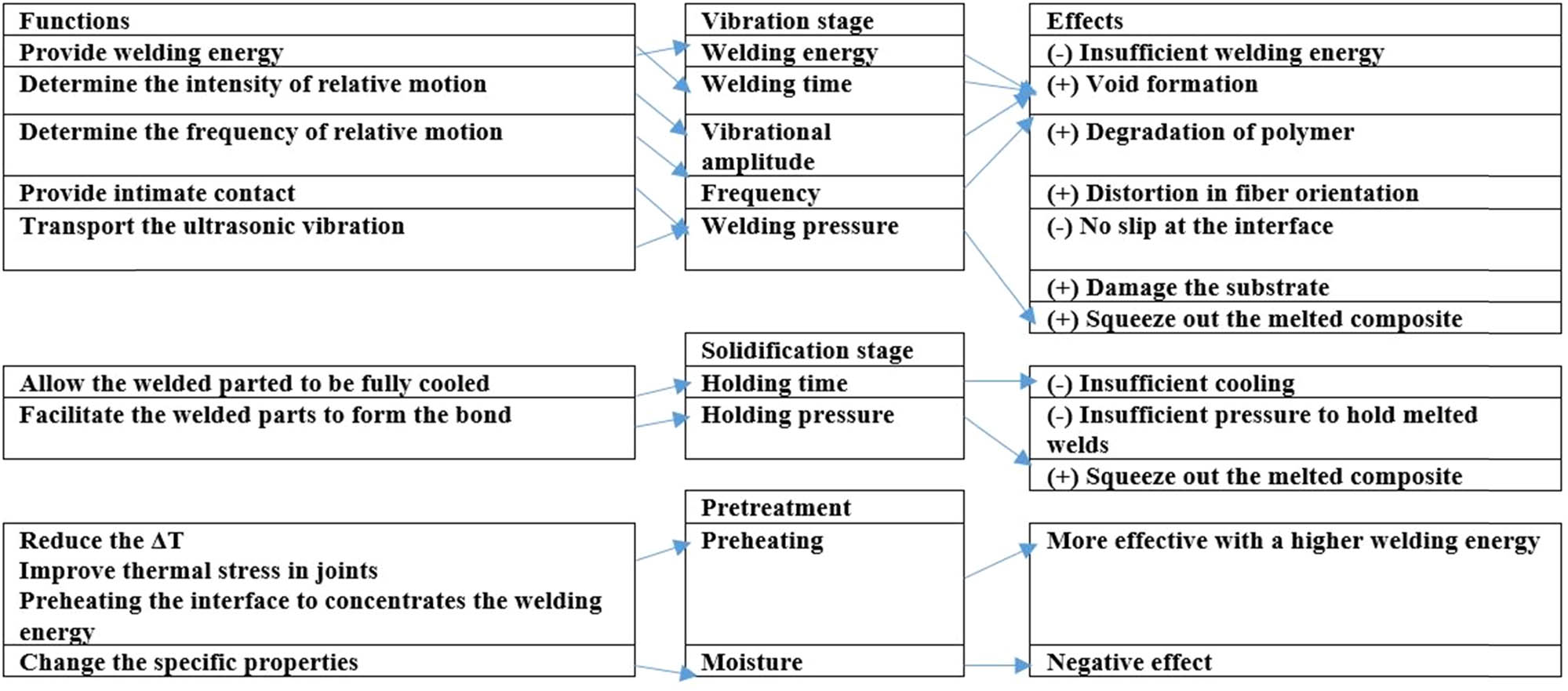 |
Note: The (+) sign means high value and (−) sign means low value.
By studying the welding quality of CF/PA6 welded by USW without ED utilizing a servo-driven welder, the process parameters were found to have a direct relation with bonding efficiency and the overall welded area. Figure 67 illustrates the connection between the welding area and bonding effectiveness. It is observed that the strongest bond is produced when the welding region is near the sonotrode contact area. At vibration amplitude of 50–70% and minor amount of welding energy (i.e., 200 J), materials were insufficiently melted when the welding area is small compared with the contact area. The increase in welding force brought on by great trigger force of 1,000 N and plunging speed of 1.2 and 1.5 mm·s−1 would squeeze roughly some molten materials out of the weld region. Besides, when the welding area is larger than the contact area, it results in reducing the bonding effectiveness. Additionally, the welding time and the quantity of melted materials are influenced mainly by amplitude. However, only the first three stages and fewer melted components were visible at low energy and vibration amplitudes, resulting in a relatively limited weld area. In comparison, great energy can melt additional materials. However, because welding takes a long time, excessive melted materials might be squeezed out [248].
![Figure 67
The relation between bonding efficiency with welding area and process parameters effects [248].](/document/doi/10.1515/rams-2024-0077/asset/graphic/j_rams-2024-0077_fig_067.jpg)
The relation between bonding efficiency with welding area and process parameters effects [248].
Welding process factors, weld characteristics, and joint behavior are essential to evaluate the weld quality and are all related. The degree to which a weldment satisfies its practical necessities is the definition of weld quality. Weld attributes are a weldment’s visible traits, while weld performance is a weldment’s internal qualities. The weld quality can be circuitously defined by weld qualities and joint behavior, such as weld area, the morphology of the weld zone, and extreme LSS, founded on the relationship of the previous four sets of variables [250]. Figure 68 shows the correlation between weld quality, characteristics, and joint performance. Overall, the ideal heating time and the optimum frequency in USW were found to be 3–4 s and 20–40 kHz, respectively, in large-scale consideration [295]. An increase in welding strength was reported due to high vibrational frequency, which also increases material vibration [296,297]. Moreover, it is anticipated that USW will always have a very high instantaneous strain rate due to the nature of the process, which involves a very high strain due to the high vibrational frequency. It has been established that a substantial strain rate affects the crystallization of the polymer [298–301], as a further enhancement of the strain rate.

Relationship between welding quality, welding characteristics, and joint performance.
4 Improvement of USW process by ED and interlayer
The heat generated in the overlapped welded area is a difficulty caused by the high-frequency stress; this heat is due to vibrational energy. The ED works as heat dissipation, where it molds to initiate melting [302]. It is possible to use a tie layer (an interlayer made of substrate material) instead of ED in the USW [303,304]. The ED consists of resin protrusions on the welding surfaces, and it is artificial [64]. Table 4 presents a tabular classification based on the type of USW machine used to join different types of CFRP with an interlayer between the two welded specimens. However, the ED is usually made of TPCs such as PEI, PE, PEEK, or PSS. Besides, it is generated in different shapes. For example, previous studies presented a beneficial influence of the PPS film and its composite crystallinity on the tensile characteristics [305,306]. Although interpreting the difficulty of introducing ED, as in USW, on sheet components (between the two specimens to be welded) is considered one of the main limitations of fiber-reinforced material [73]. However, this process is compatible with adding polymer-coated material in dissimilar welding [307]. Figure 69 shows a graphical diagram of contact initiation and propagation for USW with/without ED [240]. Furthermore, Singh Rana et al. [308] utilized the USW to join specimens made of sustainable polymers and design by printed molded by implementing EDs with various geometries.
Classification of CFRP joined by USW based on type of USW machine with using ED or an interlayer
| USW Type | CFRTP | Interlayer material | Parameters | Shape of sonotrode and number of spots | Summary | Ref. | |||||
|---|---|---|---|---|---|---|---|---|---|---|---|
| Power (W) | Welding time (s) | Frequency (kHz) | Overlap area (mm2) | Amplitude (µm) | Force and pressure | ||||||
| 20 kHz Rinco Dynamic 3000 ultrasonic welder | CF/PEI | PEI | 3,000 | NA | 20 | 12.7 × 25.4 | 51.8–86.2 | 300,500 and 1,500 N | Cylindrical SSW | A neat of PEI film has been used as an ED between two composite layers. After USW, a metaphysical model was developed by the FE to study the phenomena during heating phase and the machine accuracy and welding quality | [321] |
| Output |
|
||||||||||
| Electrical motion 20 Ultrasonic welder Rinco ultrasonic | CF/PEEK | PEI | NA | 1 | 20 | NA | 32 | 3,000 N | Cylindrical SSW | The PEI as an ED has been used to avoid PEEK matrix melting | [336] |
| Output |
|
The physical changes were evaluated followed by investigation of parameters effects on single LSS and fracture surface | |||||||||
| Operating high-quality welding by controlling process parameters and the mechanical strength with the temperature generated during welding | |||||||||||
| By using similar parameters in USW, the mechanical strength and interfacial fracture will also be similar | |||||||||||
| KZH-2026 multifunction USW machine | CF/PA6 | Henkel 5089 Ep-Ethyl-4-methylimidazole (2,4-EMI) and Hydroxyethyl | 2,600 | 2 | 20 | 12.5 | 25 | 312, 623, 935 N | Cylindrical SSW | A repairing test was done by ultrasonic pulse using adhesive-bonded in lap-shear CF/PA6 with 30 wt%, the process was done under different set of parameters (force, oscillation time). The transient temperature was measured and the impact of the repaired process on the strength of joint was investigated | [70] |
| Output |
|
||||||||||
| 20 kHz micro-processor controlled ultrasonic welder | CF/PEKK | Arkema PEKK 7002 polymer film | 6,200 | NA | 20 | 12.7 × 25.4 | 86.3 | 1,000 N 3.1 MPa | Rectangular SSW | Study the enhancement of fiber orientation in the plies close to the weld line on the USW, taking into consideration heat generation, transformation, and the impact on edge defects | [337] |
| Output |
|
The ED covered almost all intended welding area | |||||||||
| Rinco Dynamic 3000 microprocessor-controlled ultrasonic welder | CF/PEEK -HEXPLY 913 unidirectional CF/Ep | PEEK as ED (neat layer), PEEK coating on CF/Ep | 1,500, 2,100 | NA | NA | 12.7 × 25.4 | 72–120 | 300, 1,500 N, 4.7 MPa | Rectangular SSW | Preventing degradation of CFRTP welded by USW at high temperature by using very short heating time, the fractographic and FTIR analyses have been used and the displacement-controlled welding has been used | [190] |
| Output |
|
No. of samples in each welded joint type ≥5 | |||||||||
| The coating layer was used only in one type of welding | |||||||||||
| It is necessary to keep the heating time low in second to avoid thermal degradation | |||||||||||
| The thin coating layer of PEEK works as heat shield by using the ultra-fast USW | |||||||||||
| Ultrasonic TWTP | PLA/POM IPS | PLA (as IPS) | NA | 1–5 | 28 | NA | 30 | 0.1–0.4 MPa | TWTP | Welding of dissimilar material was achieved by IPS material, outstanding plasticity property was observed, and the welding time and pressure have high impact on welding strength. Owing to ultrasonic TWTP, low mechanical strength of the matrix and IPS restricted the welded strength | [279] |
| Output | The yield strength (YS) of PLA = 58 MPa, POM = 61 MPa, and PLA/POM = 52 MPa
|
Thermodynamic properties were studied | |||||||||
| Ultrasonic TWTP | PMMA/POM | PLA FGM as (IPS) | NA | 1–4 | 28 | NA | 30 | 0.1–0.4 MPa | TWTP | The TWTP process was used to join the immiscible TPCs without adhesive, and the third phase FGM of IPS was prepared. Microstructure, mechanical, and thermal properties were investigated | [277] |
| Output |
|
47 MPa was recorded as the peak of welding strength, which is only 80% of tensile strength of POM. The welded structures were divided into four parts | |||||||||
| HiQ DIALOG SpeedControl ultrasonic welder | CF/PEEK CF/Ep | PEI | NA | NA Solidification 4 | NA | 12.7 × 25.4 | 86 | 1,200 N | Rectangular SSW | Investigate the sensitivity of heating time at different heating time. ED was added to avoid heating. The microstructure observations were correlated to weld strength. Displacement control welding was used. 250 specimens were assessed and results were compared with the PEEK-PEEK configuration | [338] |
| Output |
|
An FE model was developed by using ABAQUS software | |||||||||
| Rinco Dynamic 3000 ultrasonic welder | CF/PEI-CF/Ep | Neat PEI film and PEI as ED& | 0–3,000 | 4 | NA | 12.7 × 25.4 | 86.2 | 1,500 N | Cylindrical SSW | The potential of a coupling layer of PEI to promote heat generation was investigated, as findings overheating in CF/PEI adherend were observed in case of no loose ED or coupling layer | [261] |
| Output |
|
A high-strength weld was found in CF/Ep and CF/PEI welding | |||||||||
| As overall, this study investigates 4 different types of joints | |||||||||||
| Hence the same amount of time and load were used for solidification. Both displacement and energy dissipated were used as a controller | |||||||||||
| The CF/Ep with PEI layer-PEI ED-CF/PEI was set as a reference welded case | |||||||||||
| USW machine with AWC-6 microprocessor controller | CF/Ep-CF/Elium | Elium (ELP ELF) | NA | 3 | 20 | 25.4 × 25.4 | 48.75 | 5 bar | Square SSW | The feasibility of using USW to weld carbon/Elium to carbon/Ep by using two different joint configurations (ELF & ELP) as a coupling layer; results were equated with Elium samples as a baseline weld. Two different amounts of ELP were used to examine the effect of volume | [284] |
| Output |
|
Using the ELP was found to enhance the LSS and welding quality while it is the opposite in case of using ELF where it resulted in poor bonding strength | |||||||||
| HiQ DIALOG Speed Control ultrasonic welder | CF/Ep-CF/PEEK | PEI | 5,000 | 4 | NA | 25.4 × 12.7 | 60 and 86 | 400–1,200 | Rectangular SSW | Investigate the sensitivity of USW for welding dissimilar composites and study how varying the process parameters enhance the welding strength and quality. The ED made of PEEK film was used to enhance the local heat generation | [282] |
| Output |
|
For each configuration, three welded specimens were used | |||||||||
| The design of experiment was applied by using ANOVA | |||||||||||
![Figure 69
The heat generation and propagation flow in USW toward welding with/without ED [240].](/document/doi/10.1515/rams-2024-0077/asset/graphic/j_rams-2024-0077_fig_069.jpg)
The heat generation and propagation flow in USW toward welding with/without ED [240].
Moreover, it has been shown that there are some difficulties in the USW process in the absence of ED or interlayer in between the specimen [30]. The ED usually has incredibly higher viscoelastic heating and tremendous strain during the welding process than the bulk material; the reason is owing to the small cross-section of ED [309]. Furthermore, the stability of welding quality depends on ED [309]. The ED, used in TPCs welded by USW, is made of traditional molded matrix resin on the consolidated adherents in a second production step [269,310]. Meanwhile, the geometry of ED is one of the critical factors that may affect the USW technique besides vibration amplitude and welding time [259]. Linear ridges with semi-circular, rectangular, and triangular cross sections are the shapes of ED due to plastics industry procedures [311]. Nonetheless, Khatri et al. [312] investigated the efficiency and welding quality of joining PEEK fabricated by AM with CF/PEEK and joined by USW by implementing various shapes of ED. It has been observed that the circular ED obtained greater failure forces associated with mesh-shaped counterparts ED.
Furthermore, the welding process and its results are highly affected by the orientation of the ED, and its shape [12]. The ED surface is usually made of resin protrusions which helps to perform the weld, and the welding quality is directly influenced by the shape and size of ED as well as the morphology of these resin protrusions [3]. In addition, it has been revealed that by increasing the geometry complexity of ED and it is surface to have an optimum ED design, well cause to enhance welding quality [313]. Koyanagi et al. [314] investigated CFRP joined by USW using an ED associated with a numerical model. An ED made of poly-vinyl-butyral (PVB)/graphite nanoplatelets film has recently been produced and employed to join CF/Ep by USW by Cilento et al. [315]. Besides, a modern ED made of stainless steel mesh has been utilized in USW for joining CF/PA66, and the enhancement of ED mesh size on the welding quality has been investigated [316]. Moreover, it has been observed that a smaller wire diameter of the mesh ED and great wire spacing lead to good welding quality. Li et al. [316] explored the CF/PA66 joined by USW by implementing an ED made of stainless steel with mesh geometry, as illustrated in Figure 70. Besides, it revealed that a higher amount of pore defects in the joint were obtained by small wire spacing. However, a wire which has a great diameter causes the absence of fusion defects. Also, the energy concentration effect was reduced by a large mesh area. Moreover, it has been revealed that the damage in the fusion zone can be reduced to minimal and eliminate thermal degradation by implementing various types of PEI ED [317].
![Figure 70
(a) 2000XD USW machine, (b) the welding process schematic, and (c) the stainless steel mesh ED [316].](/document/doi/10.1515/rams-2024-0077/asset/graphic/j_rams-2024-0077_fig_070.jpg)
(a) 2000XD USW machine, (b) the welding process schematic, and (c) the stainless steel mesh ED [316].
Korycki et al. [318] examined the effect of ED thickness on joint quality and thermal diffusion during USW of CF/PEEK. The PA6 film has been employed as an ED to join cold rolled steel with CFRTP by USW [319]. Also, the authors addressed the effects of preheating temperature and welding energy on the joint characterizations (microstructure and mechanical). The heating of FED was excited by the surface friction, which results in time variation to melt the ED [8]. A fragile weld line identical to the thickness of resin-rich regions within the adherents in TPC/TPC welding has been observed because the most molted ED is squeezed out of the overlap welding [64]. The adhesion and displacement of ED and FED during USW were investigated [320,321]. Furthermore, to attenuate the upshot of adverse fiber location at the interface, it has been recommended to utilize an ED made of TPCs, which emphasizes the material weldability [302]. On the other hand, the ED may have some weaknesses, like limited reduction in fiber [234,252,322], although it provides good weldability and welding quality with using ED. Figure 71 presents a schematic of welded layers with an FED [244]. The impact of using ED made of PVB NCs for joining TSCs by USW has been investigated by Cilento et al. [323].
![Figure 71
Principle of USW TPCs with an FED [244].](/document/doi/10.1515/rams-2024-0077/asset/graphic/j_rams-2024-0077_fig_071.jpg)
Principle of USW TPCs with an FED [244].
Furthermore, a joint was performed with using ED, where the ED has melted and performed the joint in between the two pieces, after the ED melts, solidifies and cools down. The ED melts due to the generated friction heat by the effect of ultrasonic vibration [172]. In addition, the reason for melting the ED without distortion in the micro-grooves is that the ultrasonic amplitude and applied force were lower than that needed for ultrasonic hot embossing. Nonetheless, Wang et al. [324] investigated the weldability of CF/PA6 as well as PA6 joined through a servo-driven USW with/without using ED. For the purpose of examining the impact of the ED on welding process parameters in joining CF/PPS and joining CF/PA6, the qualitative examination of displacement during the joining process is presented in Figure 72. When the triangular ED melts, the sonotrode descends rapidly. When the material melts at the faying surface of the triangle, it descends slowly. Also, in the CF/PA6 30 wt.% welded without using ED, it was detected that the power increases grow abruptly and then remains stable with minor variations [37]. Furthermore, incase of applying two differnet types of ED as 4T ED and FED to join CF/PPS similar vibration time, welding energy, LSS and maximum dissipated power were obtained. Also the obtained results of FED were similar to triangular ridges moulded on one slack stripe of neat resin and triangular ridges moulded on the surface of the bottom adherend. Besides, the sonotrode displacement was analysed, it was shown that the sonotrode hold its initial position before starting its gradually descending [260]. However, since ED is not used for USW of CFRTP, the sonotrode descends linearly vertically at a constant speed.
![Figure 72
The variation displacement and power during USW for diverse surface settings: (a) CF/PPS with using triangular ED (vibrational amplitude = 86.2 μm, holding force = 500 N); (b) CF/PPS with using rectangular ED (vibrational amplitude = 86.2 μm, holding force = 500 N); (c) CF/PA6 without using ED (vibrational amplitude = 36 μm, holding force = 200 N [37].](/document/doi/10.1515/rams-2024-0077/asset/graphic/j_rams-2024-0077_fig_072.jpg)
The variation displacement and power during USW for diverse surface settings: (a) CF/PPS with using triangular ED (vibrational amplitude = 86.2 μm, holding force = 500 N); (b) CF/PPS with using rectangular ED (vibrational amplitude = 86.2 μm, holding force = 500 N); (c) CF/PA6 without using ED (vibrational amplitude = 36 μm, holding force = 200 N [37].
An investigation on a unique zero-flow welding method for continuous USW of TPC plates has been carried out. The suggested method produced robust welds before the squeezing flow starts at the welded interface. The outcomes demonstrate the viability and point to the possibility of rapid high-strength welding between TPC plates. In addition, the relation between LSS and welding speed for 60, 80, and 100 mm·s−1 has been examined. The outcomes show that, overall, the LSS values at 60 mm·s−1 are greater than those at 80 and 100 mm·s−1 [325]. For investigating the mechanical properties of CF/PEEK joined by USW through implementing a spot ED, a double LSS was performed, and the outcomes were likened with MFs results; the fiber-matrix debonding failure for the welded specimen causes naked fiber bundles and resin-rich pockets to become evident on the uppermost ply of the adherend. However, the first ply is the only part of the adherend with this intralaminar damage, while the remainder of the layers were unaffected. In contrast, matrix cracking and delamination severely destroy the laminate structure of the MFs joint. The part’s upper side deforms due to the Hi-Lok® fastener head penetrating it. A full description of the through-the-thickness damage is given by the cross-section micrographs of the welded samples, as illustrated in Figure 73 [72].
![Figure 73
The micrographic cross-sections of spot-welded joint of CF/PEEK after DLS tests. The scale bar for 2 mm is presented in the top figure. The below images are the magnification of the parts in the white boxes of the top one [72].](/document/doi/10.1515/rams-2024-0077/asset/graphic/j_rams-2024-0077_fig_073.jpg)
The micrographic cross-sections of spot-welded joint of CF/PEEK after DLS tests. The scale bar for 2 mm is presented in the top figure. The below images are the magnification of the parts in the white boxes of the top one [72].
Tao et al. [256] compared the morphology observation of a weldment processed with and without ED by using FED and noticed a considerable reduction in the HAZ width at identical welding time and in the number of cracks, which is due to the melting of the ED absorbing a particular amount of heat and decreasing the impact of heat on the matrix. Accordingly, using FED increases the joints’ strength with rising the PEEK resin gratified, and improves the attentiveness of ultrasonic energy at the interface. Besides, the ED directly affects the fracture surface, as shown in Figure 74.
![Figure 74
The fractured surface morphology of (a) CF/PEEK joint without using ED at 0.9 s, (b) region A with high magnification, (c) the joint with FED at 0.9 s, and (d) region B with high magnification [256].](/document/doi/10.1515/rams-2024-0077/asset/graphic/j_rams-2024-0077_fig_074.jpg)
The fractured surface morphology of (a) CF/PEEK joint without using ED at 0.9 s, (b) region A with high magnification, (c) the joint with FED at 0.9 s, and (d) region B with high magnification [256].
Some variations were noticed by comparing the micrograph results of the fracture surface of cross-ply laminate with and without FED. Figure 75 presents the fracture surface of cross-ply with FED after the LSS; fibers are observed in Figure 75(a), the fiber bundle is parallel to each other, and the fracture is considered narrower without FED, and the absence of fractured fibers (Figure 75(b)–(d)). A slip in the fracture surface caused by the pull-out of the fibers at the edge of the free-edge side at point D of the welding area was observed. Moreover, at point E, there is a flat fracture surface. However, at point F the fracture befell at the edges of the grip side and the middle of the welded area, this fracture mode is similar to the fracture caused without FED [6]. Additionally, an FE model was developed to examine the fracture mechanism of cross-ply laminate with and without the FED. Where the CF/PEI joined as a similar welding with FED, the heating phenomena and thermal degradation were examined. The analysis of the fracture surface during ideal welding indicated matrix degradation symptoms, resulting in less consistent quality. Moreover, it is probably caused by a higher heat generation rate in the substrates and ED and higher temperatures close to the ED melting temperature [238].
![Figure 75
The fracture surfaces of cross-ply laminate joint of CF/PA6 with implementing FED after LSS [6].](/document/doi/10.1515/rams-2024-0077/asset/graphic/j_rams-2024-0077_fig_075.jpg)
The fracture surfaces of cross-ply laminate joint of CF/PA6 with implementing FED after LSS [6].
A further investigation studied the CF/PEI similar welding using a different configuration of ED by changing the orientation parallel to the plates, perpendicular to the plate, and two EDs parallel to the plate [3]. Besides, triangular EDs were molded into laminated composite surfaces using a hot platen press. LSS samples were created to examine the effects of numerous ED configurations and the EDs’ orientation concerning the load. It is revealed that several transverse EDs were significantly effectively filling the overlap area once they melted, resulting in minimal damage to the fiber at the welding. The effect of changing ED geometry and the configurations on the welding quality were studied. As a finding, the multiple EDs improved the overlap welded area without hindering the resin flow. As well as, by using multi-EDs, a remarkable reduction in fiber distribution in the outer layers of the weldment was observed. However, the parallel ED configuration provided more welded area scatters than the transverse EDs [3]. Furthermore, the high number of scatters makes studying the ED configurations on mechanical properties more difficult. Nevertheless, Wang et al. [326] employed the genetic algorithm and neural network to optimize the process parameters and predict the weld strength, including welding time and pressure of USW that were implemented to join CF/PEI. Moreover, Villegas and Palardy [278] explored whether using triangle ED in USW instead of FED may significantly shorten the required heating time to reach supreme weld strength. The significant finding was that, in the particular scenario, the triangle ED did heat up, melt, and collapse almost twice more quickly than the FED, and this difference was substantial. However, the integrated triangle ED did not require significantly longer heating time to reach the optimum weld strength compared to FED. However, a published review found that many studies joined the TPCs to the TSCs by using an interlayer made of TPC films as an interlayer or coupling layer [37]. Furthermore, the PEI has been used as an interlayer to couple different matrix’s of CFRTP based on its unique characteristics under the co-curing process [193–195]. The porosity produced by resin sublimation created in C/Ep adherents after welding is concluded by comparing a study that used 50 µm thickness of PEI interlayer vs another study that used 250 µm [192]. Nevertheless, when using PEEK as a coupling layer for dissimilar joints by USW, it is usually not soluble in uncured Ep systems owing to the high chemical resistance [5,94,190]. Additionally, Wang et al. [327] explored the enhancement of welding time on the welding quality of CFPEEK, by using an ED which was manufactured by implementing the ultrasonic embossing. The obtained outcomes show that using the ultrasonic embossing helps on concentrating the welding energy which decreases the dispersion and randomness of the weld distribution as well as enhances the failure load by 30% compared with joining without using ED. Furthermore, Rubino et al. [328] developed a TPCs hybrid interlayer to join GFRP by USW. Figure 76 represents the graphic demonstration of the manufacturing route and the USW set-up. Meanwhile, Tian et al. [329] explored the effect of pre-pressing ring on the welding quality of USW in joining short CF/PA6 composite.
![Figure 76
The schematic of the procesing route of manufacturing process of TPs/TSs hybrid composite to USW of the fabricated laminates [328].](/document/doi/10.1515/rams-2024-0077/asset/graphic/j_rams-2024-0077_fig_076.jpg)
The schematic of the procesing route of manufacturing process of TPs/TSs hybrid composite to USW of the fabricated laminates [328].
Generally, the size, geometry, and the number of implemented ED have a direct impact on welding, since the ED affects the resin flow and heat generation [256]. Besides, the welding strength was found to be influenced by the ED much more than vibrational time and welding force [330]. Some of the most effected properties by ED are illustrated in Figure 77. However, apart from the mentioned and discussed studies, the literature is rich with further investigations which focused on overcoming the drawback of the traditional EDs for enhancing the welding quality. For instance, Jongbloed et al. [331] developed a compliant mesh ED made of woven polymer to enhance the uniformity of the weld. The obtained results reveal that the developed mesh ED enhances the LSS and the weld uniformity. Furthermore, Brito [332] recorded the best welding results by the combination of increasing welding force with implementing a discontinuous ED film. However, the impact of ED is varied as long as the material of specimens to be welded is varying. For instance, in some cases, the triangular ED can achieve more favorable results than FED in welding polyethylene [333]. Moreover, recently Bose et al. [334] implemented the developed methodology of water-submerged USW (S-USW) with three various types of ED to join CF/PA. This methodology enhances the welding strength as well as mitigates the material degradation that may be caused by the rapid heating which occurs during the traditional USW process. Besides, the obtained results by using the S-USW with a semi-circular ED recorded 16.4 MPa as welding strength, while it reached 14.3 MPa and 14.69 by using the traditional USW with triangular and rectangular Eds, respectively. In a further investigation accomplished by the same authors, Bose et al. [335] implemented the S-USW to join PVC/PVC and PP/PP. The obtained results show that the LSS of PP/PP and PVC/PVC increased by 21 and 39%, respectively compared with the results obtained using traditional USW.

The properties most affected by the ED.
5 Challenges
The main throwback of USW is that it is still limited in assemblies with considerable overlap area [238]. Likewise, one of the most remarkable challenges of USW is that for each new welded spot, a new set of boundary conditions must be reset [170]. Implementing the USW process is till limited since there is no significant quantitative evaluation methodology for defining the bonding strength [339]. Joining assemblies with huge overlaps by USW is still defied and limited [238]. The ultrasonic amplitude in the USW is inhomogeneous as usual over the sonotrode area, which makes the unfilled molten polymer more challenging on large areas near micro-cavities. Furthermore, the energy output of piezo stacking, driven in resonance for achieving high amplitude in the USW, controls the sonotrode; this significantly controls the overall contact area processed in one step [172]. In the case of joining TPCs either in similar/dissimilar joint USW, a dimness in the composite structures’ assembly, which tends to fail first, may present. This means the damage must be detected to prevent local degradation and evade a catastrophic failure [77]. Although owing to great heat generation at the interface throughout the USW process, the thermal degradation of the thermoset substrate is a severe dilemma to be determined [37]. Besides, damage growth occurs in the interface between the weldment components that are joined by SSW of USW [340]. Moreover, the physical mechanisms of the USW are still under debate, subsequently predicting the optimum sets of process parameters that led to optimum welding quality and welding strength remains a challenge [341]. Besides, determining the optimum amount of the reinforced wt% to be added to the polymer matrix which effects the welding strength is challenging, for instance, by increasing the GF above 20 wt% in PP matrix the welding strength was reduced [342]. Additionally, Tirband et al. [343] enhanced the welding quality of GF/PMMA and GF/PP, respectively, by using the laser surface treatment approach where the obtained results show a superior interaction between the coupling layer and the treated surface parts were achieved. In addition, avoiding the trapped air and restricting the melted polymer flow during the USW process are challenges that can be avoided by implementing an optimum ED design [344]. However, finding the optimum ED for each specific USW is an essential concern. Furthermore, increasing the energy may cause a slight reduction in the LSS [345]. Moreover, the necessity of higher fiber content for sufficient energy focusing in the ED is a considerable challenge in USW for acousto-ultrasonic composite transducers, by comprising a piezoceramics materials in reinforced polymer matrix [346]. Likewise, finding the optimum welding temperature is essential since increasing the temperature reduces the required welding time, in contrast the molecular diffusion rate limits the welding process at high temperature [347]. However, it has been reported that the ultrasonic vibration treatment as a post-processing approach can improve the joint strength in applications that require medium to high welding strength at optimum process parameters [348]. Apart from the mentioned advantages and disadvantages in Figure 4, Figure 78 presents further advantages and limitations of USW process.

Further advantages and limitations of USW process.
In order to improve robustness and reliability and to develop continuous welding of complex and more significant parts, there is an essential need to develop a consistent FE models with the up-clambering of using USW in industrialization [325]. Some studies developed an FE model to study different mechanical properties such as stress distribution and stress-strain, although FE analysis of CFRTP is still considered slightly limited. In addition, mathematical modeling and numerical examination remain deficient [22]. Nonetheless, by investigating the thermal coupling during USW process by developing FEM by Zhang and Li [349], it was found that the main reason for bond formation in USW is the severe restricted plastic deformation. Furthermore, the accurate and realistic mock of the vibration and heating performance of TPCs in the USW process was allied with excessive difficulties. In certain, the solution by essential frequency and temperature that dependes on mechanical stiffness and damping behavior in the high-vibrational frequency range are inefficiently, which cause to have limited numerical expectation of the weldability in the progress of USW technique [350]. Additionally, there is an essential demand for optimum specimen’s geometries as well as further progresses in the assessment routine to enhance the analyzable temperature range combined with the quality of the generated material. The developed model based on reverse engineering approach is shown in Figure 79.
![Figure 79
The schematic of material data determination overview based on reverse engineering approach [350].](/document/doi/10.1515/rams-2024-0077/asset/graphic/j_rams-2024-0077_fig_079.jpg)
The schematic of material data determination overview based on reverse engineering approach [350].
Moreover, Yang et al. [351] examined the contact performance and the temperature characterization in USW of CF/PA66 by developing a mathematical modeling as shown in Figure 80, through implementing the harmonic balance methodology. The obtained results show that in NL contact and heat generation there was a certain separation between the specimens and the friction heat generated in the earlier welding stage, while in viscoelastic heating, no significant separation was recorded. Besides, increasing welding time and vibrational amplitude produced a remarkable increase in the temperature of the welding surface. However, by analyzing the spatial and temporal temperature enhancement during the USW of FRTP numerically as shown in Figure 81, the obtained results show that there is an essential need to focus more on the viscoelastic heating since it increases the polymer matrix temperature to the decomposition temperature [352].
![Figure 80
The computational methodology model for analyzing the thermal mechanical coupling [351].](/document/doi/10.1515/rams-2024-0077/asset/graphic/j_rams-2024-0077_fig_080.jpg)
The computational methodology model for analyzing the thermal mechanical coupling [351].
![Figure 81
The numerical modeling by using the explicit finite difference method for various spots in USW: ω is the angular frequency, Z
0 is the applied displacement amplitude, F
w is the applied static weld pressure, u
0 is the interfacial slippage amplitude, μ(T) is the friction coefficient, ε
0 is the resolving strain amplitude, σ
0 is the interface pressure amplitude, T is temperature value, E″m(T) is the matrix loss modulus, E*m(T) is the matrix complex modulus, c
p(T) is the composite specific heat capacity, k is the thermal conductivity of the composite, and E*c(T) is the composite complex modulus [352].](/document/doi/10.1515/rams-2024-0077/asset/graphic/j_rams-2024-0077_fig_081.jpg)
The numerical modeling by using the explicit finite difference method for various spots in USW: ω is the angular frequency, Z 0 is the applied displacement amplitude, F w is the applied static weld pressure, u 0 is the interfacial slippage amplitude, μ(T) is the friction coefficient, ε 0 is the resolving strain amplitude, σ 0 is the interface pressure amplitude, T is temperature value, E″m(T) is the matrix loss modulus, E*m(T) is the matrix complex modulus, c p(T) is the composite specific heat capacity, k is the thermal conductivity of the composite, and E*c(T) is the composite complex modulus [352].
To investigate the welding quality by using the vibrational signal, Zhu et al. [353] employed variational mode decomposition and Hilbert-Huang transform (HHT) to acquire the HHT spectrum, where a support vector machine (SVM) model has been developed and trained by using the Bayesian optimization (BO) algorithm as shown in Figure 82 to define the optimal parameters for weld quality categorization and recognition. The outcomes reveal significant performance, accomplishing 95.35% accuracy rate. This designates that there is remarkable potential for virtual detection of CFRTP welding quality through ultrasonic vibration signals.
![Figure 82
The BO-SVM flowchart [353].](/document/doi/10.1515/rams-2024-0077/asset/graphic/j_rams-2024-0077_fig_082.jpg)
The BO-SVM flowchart [353].
Furthermore, despite the overall advantages of polymers, such as mechanical properties and lightweight, they also have some drawbacks. For instance, the major drawback is that it is not simple eco-friendly, where researchers and organizations have expressed tremendous concern about the development of non-recyclable plastics in the environment by developing plastic that is recyclable or biodegradable.
For recyclability purpose, utilizing biodegradable polymers have several environmental benefits such as reducing carbon dioxide emissions regeneration of raw material, and biodegradation [354]. Some of the commercial polymers such as PA6, PA66 were found to be biodegradable and were proved under the SEM, FTIR, and EDS analysis [355]. However, the PA66 can be replaced by the bio-based polyamide 56 (PA56) [356]. Besides, the PBS is also completely biodegradable [357]. Moreover, polyesters such as PET can be replaced by natural polymers such as polysaccharides (wood, pectin’s chitosan, and gum) and animal and plant proteins (collagen, soya, gluten, gelatin, casein, and whey). Besides, the PLA can be produced by both natural resource (rice, corn, sugar beets, etc.) and chemical resource. In contrast, PEEK is an example of non-biodegradable and is unfeasible to recycling [358]. Nonetheless the biodegradation process is enhanced by numerous factors such as the morphology structure of the polymer, the molecular weight as well as the chemical treatment process [359]. In addition, the key features of biodegradable polymers are, the potentially undesirable mechanical qualities, the high rate of decomposition and their primarily hydrophilic nature. Meanwhile those features can be enhanced by mixing natural and synthetic polymers [360,361].
6 Discussion
Diverse types of joining techniques can be employed to join similar and dissimilar CFRPs. One of the best-developed techniques is the USW. The joining occurs due to the heat generated by the vibrational amplitude and ultrasonic wave. The heat is generated between the interface layer, and it reaches these points by the welding tool known as horn/sonotrode. Usually, an ED, interlayer, or coupling layer, is used between the two layers (adherend) and must have a melting temperature inferior than the melting temperature of the polymer matrixes. The parts that need to be joined are exposed to an ultrasonic vibration. Remarkably, viscoelastic heating is the most significant of the various heating mechanisms in the USW. The friction of the plastic molecules rubbing against one another is to blame. As more deformation is produced, more heat will be generated.
Moreover, USW welding machines are similar, with some differences, such as frequency value or range and the geometry of the sonotrode. The USW machines for joining polymers have two main classifications which are continuous welding and the spot welding which are further classified as single, double, and multi. However, only a few studies investigate the impact of sonotrode geometry on enhancing the welding process parameters and the quality of welding. The range of process parameters, including power, energy, holding time, welding time, vibration time, holding time, vibrational amplitude, and frequency, are different based on the type of USW machine. Furthermore, accurate joint designs are ideal for concentrating ultrasonic energy at the welding interface. The USW process features are also strictly connected, demonstrating unusual sensitivity to the holding and tolerances of the components required to weld. The mechanical test shows that by comparing the LSS findings of coupling layers made of PEI and PEEK, both have the same thickness in dissimilar welding of CF/Ep and CF/PEEK, both materials show nearly comparable LSS values. In contrast, the USW process did not lead to any substantial damage in the mechanical properties in the interphase or the adherend in dissimilar welding. Based on the literature, some welding processes are controlled by other process parameters, such as welding energy, which may affect the required welding time and vibration time. Also, some parameters impact welding strength and mechanical properties more than the rest of the USW process parameters such as, welding time and welding force. Meanwhile, some parameters, such as frequency, are considered as a constant in most studies. However, raising the vibration time may cause an additional concentration of heat at the interface, and the temperature would reach the melting temperature of the polymer matrix. Moreover, an adequate flow in the resin at the interface was noticeable. Consequently, the interfacial bonding formed the intermediate between the two specimens of base materials by the resin fusion. Simultaneously, extreme heat can also be applied to the CFRP matrix. Owing to the significant variance amongst the thermal expansion coefficients, the voids appeared at the interface of the polymer resin and the CF and cracks. Consequently, in many cases, the bonding cannot be achieved without using ED or interlayer in USW. The energy-controlling mode is recommended for welding strength, and the displacement-controlling mode is preferable for welding quality. Nevertheless, one of the most significant essential rewards of USW, above short welding time, is that it is an environmentally benign method, and the joined welded pieces, after the USW, do not require any additional cleaning or treatment. Due to the nature of the process, which entails a very high strain due to the high vibrational frequency, USW is expected to have a very high instantaneous strain rate, which will affect the crystallization accordingly. Furthermore, the unique influences of fiber types and matrix scatterings on USW weldability are still unclear, and owing to the numerous physical properties of various materials, USW may have a more substantial impact on mechanical behavior and welding strength than others, including their melting and acoustic features. Besides, the weldability of various materials is identical.
The USW is a very effective method for joining CFRTPCs and CFRTSCs, whether by single or multiple spot welding. It can fabricate joints in comparably quick cycle times, and they are distinguished by performance that is equivalent to or better than that of mechanically or adhesively fastened joints. In order to achieve either growing welding pressure in a very short welding time or vice versa, a longer duration with less welding pressure is required; in this manner, the USW technique creates the entire joint between the layers. However, welding with high welding pressure and a short welding period causes insufficient heat dispersion, which prevents the acquisition of any anticipated junction. Furthermore, modern USW has made displacement-controlled welding possible, and this technique has numerous advantages over time, including energy-controlled welding. The surface friction causes the ED to heat up, and the time it takes to melt the EDs can vary. Unwelded portions occasionally have shiny, smooth mating fracture surfaces, which was indicative of an adhesive failure at the welding interface, which was caused by the interaction of rapid heating and relatively low temperatures in the overlap’s center. While there is a large variety of resin volumes for which welds with a reasonable strength level can be achieved, an excessive quantity of resin at the welding interface causes a reduction in welding strength, as proven by previous studies. As an observation from the literature, most researchers have used PEEK, PEI, PE, Nylon (PA6, and PA66), and a few studies investigate the CFRTP (Elium®) and PPS. There are still some restrictions since when heating the polymers, poisonous gases can be generated; besides, despite the developed interest in natural fiber owing to its eco-friendly advantages, no records have been found on welding natural FRPs by USW.
7 Conclusion
This state-of-the-art review investigates the similar and dissimilar welded CFRP by the USW technology and discusses the welding process parameters and the pretreatment impact on the performed joint’s mechanical properties and microstructure characterizations, while highlighting the recyclability of CFRPs and the fabrication process of polymer matrixes. Besides, the improvement of USW process by using ED and the challenges of USW were also addressed. The USW is considered as the fastest joining process, capable of joining either metal matrix/polymer matrix, polymer matrix/polymer matrix, or metal/metal. The main principle of USW is to transfer the vibrational motion into heat between the two adherend surfaces.
Based on the literature reviewed, the most favorable PCs matrix to be used in USW are CF/PEEK and Nylon (CF/PA6, CF/PA66); where significant mechanical and microstructure observations were noticeable, above other types of CFRP in similar/dissimilar welding. Moreover, using an appropriate type and orientation of ED enhances the welding process, weldment strength, and weldment quality. However, some restrictions must be considered while choosing the ED, such as its melting temperature, which must be less than the melting temperature of the CFRP to be welded, and optimum design geometry of ED.
There is a direct relation between the number of spots and welding strength and quality in all types of welded matrices. While the geometry of the sonotrode primarily affects the welded area, limited studies concentrated on studying the consequence of changing the geometry of the sonotrode on welding strength and quality due to its high cost, which may lead to unclear information about the effect of sonotrode geometry as the process parameter. Most studies that focused on investigating the impact of changing process parameters considered single or dual parameters as variable, and the remaining process parameters had constant values, in order to make the investigation easier and finding the optimum values in a more straightforward manner. Based on this perspective, the welding energy, vibration amplitude and welding time are the most critical parameters that enhance the weldment performance and welding quality.
The welding strength was found by investigating the mechanical properties through a mechanical test. Commonly, only two types of mechanical tests are processed: LSS or tensile tests. However, only a few studies were interested in a fatigue test. There are no recorded data about further mechanical tests, such as hardness or impact tests. The microstructure observation found the welding quality, usually through the SEM, after failure or fracture. Besides, the FE analysis and mathematical modeling are still limited. Additionally, the welding quality is directly influenced by material qualities and the temperature distribution within the welded adherend. Nonetheless, there is still an essential need for optimum EDs for similar and dissimilar joints by USW. A review of ML for ultrasonically welded CFRP may be considered in upcoming work. The vibrational and thermal tests of the joined CFRP were not considered in this review and can be covered in further work.
Acknowledgments
The authors extend their appreciation to the KEGA grant 009TUKE-4/2023 of the Slovak Grant Agency.
-
Funding information: This work was supported by KEGA grant 009TUKE-4/2023 of the Slovak Grant Agency.
-
Author contributions: All authors have accepted responsibility for the entire content of this manuscript and approved its submission.
-
Conflict of interest: David Hui, who is the co-author of this article, is a current Editorial Board member of Reviews on Advanced Materials Science. This fact did not affect the peer-review process. The authors declare no other conflict of interest.
-
Data availability statement: All data generated or analyzed during this study are included in this published article.
References
[1] Thapliyal, S. Ultrasonic welding – a modern welding technology for metals and plastics. Advanced Welding and Deforming, 2021, pp. 1–22.10.1016/B978-0-12-822049-8.00001-3Search in Google Scholar
[2] Ageorges, C., L. Ye, and M. Hou. Advances in fusion bonding techniques for joining thermoplastic matrix composites: a review. Composites Part A: Applied Science and Manufacturing, Vol. 32, 2001, pp. 839–857.10.1016/S1359-835X(00)00166-4Search in Google Scholar
[3] Villegas, I. F. and H. E. N. Bersee. Ultrasonic welding of advanced thermoplastic composites: An investigation on energy-directing surfaces. Advanced Polymer Technology, Vol. 29, 2010, pp. 112–121.10.1002/adv.20178Search in Google Scholar
[4] Benatar, A. Ultrasonic welding of plastics and polymeric composites. Power Ultrasonics Applications of High-Intensity Ultrasound, 2015, pp. 295–312.10.1016/B978-1-78242-028-6.00012-0Search in Google Scholar
[5] Villegas, I. F. and R. van Moorleghem. Ultrasonic welding of carbon/epoxy and carbon/PEEK composites through a PEI thermoplastic coupling layer. Composites Part A: Applied Science and Manufacturing, Vol. 109, 2018, pp. 75–83.10.1016/j.compositesa.2018.02.022Search in Google Scholar
[6] Goto, K., K. Imai, M. Arai, and T. Ishikawa. Shear and tensile joint strengths of carbon fiber-reinforced thermoplastics using ultrasonic welding. Composites Part A: Applied Science and Manufacturing, Vol. 116, 2019, pp. 126–137.10.1016/j.compositesa.2018.10.032Search in Google Scholar
[7] Tierney, J. J., J. W. Gillespie, and J. R. P-EB. Ultrasonic heating. Comprehensive composite materials, In: A. K. Zweben, Ed., 2000, pp. 1029–1047.10.1016/B0-08-042993-9/00174-1Search in Google Scholar
[8] Zhang, Z., X. Wang, Y. Luo, Z. Zhang, and L. Wang. Study on heating process of ultrasonic welding for thermoplastics. Journal of Thermoplastic Composite Materials, Vol. 23, 2010, pp. 647–664.10.1177/0892705709356493Search in Google Scholar
[9] Tolunay, M. N., P. R. Dawson, and K. K. Wang. Heating and bonding mechanisms in ultrasonic welding of thermoplastics. Polymer Engineering and Science, Vol. 23, 1983, pp. 726–733.10.1002/pen.760231307Search in Google Scholar
[10] Devine, J. Ultrasonic plastics welding basics. Welding Journal (Miami, Fla), Vol. 80, 2001, pp. 29–33.Search in Google Scholar
[11] Grewell, D. A., A. Benatar, J. B. Park, and C. Hanser. Plastics and composites welding handbook, 2003.Search in Google Scholar
[12] Chuah, Y. K., L. H. Chien, B. C. Chang, and S. J. Liu. Effects of the shape of the energy director on far-field ultrasonic welding of thermoplastics. Polymer Engineering and Science, Vol. 40, 2000, pp. 157–167.10.1002/pen.11149Search in Google Scholar
[13] Benatar, A., R. V. Eswaran, and S. K. Nayar. Ultrasonic welding of thermoplastics in the near‐field. Polymer Engineering and Science, Vol. 29, 1989, pp. 1689–1698.10.1002/pen.760292311Search in Google Scholar
[14] Delzendehrooy, F., A. Akhavan-Safar, A. Q. Barbosa, R. Beygi, D. Cardoso, R. J. C. Carbas, et al. A comprehensive review on structural joining techniques in the marine industry. Composite Structures, Vol. 289, 2022, id. 115490.10.1016/j.compstruct.2022.115490Search in Google Scholar
[15] INSIGHT BR. Ultrasonic Welding Systems Market Size, Share, Growth, Forecast 2030, 2023.Search in Google Scholar
[16] Zion market research. Ultrasonic Welding Systems Market Size, Share, Growth, Forecast 2030. 2023.Search in Google Scholar
[17] Benatar, A. and T. G. Gutowski. Ultrasonic welding of PEEK graphite APC‐2 composites. Polymer Engineering and Science, Vol. 29, 1989, pp. 1705–1721.10.1002/pen.760292313Search in Google Scholar
[18] Barnes, T. A. and I. R. Pashby. Joining techniques for aluminium spaceframes used in automobiles: Part II — adhesive bonding and mechanical fasteners. Journal of Materials Processing Technology, Vol. 99, 2000, pp. 72–79.10.1016/S0924-0136(99)00361-1Search in Google Scholar
[19] Lu, H. M., A. Benatar, and F. G. C. He. Sequential ultrasonic welding of PEEK/Graphite composites plates. Annual Technical Conference – ANTEC, Conference Proceedings, Vol. 37, 1991.Search in Google Scholar
[20] Bhudolia, S. K., G. Gohel, K. F. Leong, and A. Islam. Advances in ultrasonic welding of thermoplastic composites: A review. Materials (Basel), Vol. 13, 2020, pp. 1284–1310.Search in Google Scholar
[21] Sandeep, R. and A. Natarajan. Advances in joining technologies for the innovation of 21st century lightweight aluminium-CFRP hybrid structures. Proceedings of the Institution of Mechanical Engineers, Part E: Journal of Process Mechanical Engineering, Vol. 236, 2022.10.1177/09544089211073027Search in Google Scholar
[22] Liu, Z., Y. Li, Z. Liu, Y. Yang, Y. Li, and Z. Luo. Ultrasonic welding of metal to fiber-reinforced thermoplastic composites: A review. Journal of Manufacturing Processes, Vol. 85, 2023, pp. 702–712.10.1016/j.jmapro.2022.12.001Search in Google Scholar
[23] Abbas, Z., L. Zhao, J. Deng, S. Wang, and W. Hong. Advances in ultrasonic welding of lightweight alloys: A review. High Temperature Materials and Processes, Vol. 42, 2023, pp. 1–25.10.1515/htmp-2022-0298Search in Google Scholar
[24] Pramanik, A., A. K. Basak, Y. Dong, P. K. Sarker, M. S. Uddin, G. Littlefair, et al. Joining of carbon fibre reinforced polymer (CFRP) composites and aluminium alloys – A review. Composites Part A: Applied Science and Manufacturing, Vol. 101, 2017, pp. 1–29.10.1016/j.compositesa.2017.06.007Search in Google Scholar
[25] Fan, Z., K. Bai, and C. Chen. The application of ultrasound in Joining: Principles, processes and properties. Journal of Manufacturing Processes, Vol. 101, 2023, pp. 269–299.10.1016/j.jmapro.2023.05.094Search in Google Scholar
[26] Jiao, J., J. Xu, C. Jing, L. Sheng, H. Ru, and H. Xia. Laser welding process and strength enhancement of carbon fiber reinforced thermoplastic composites and metals dissimilar joint: A review. Chinese Journal of Aeronautics, Vol. 36, No. 12, 2023, pp. 13–31.10.1016/j.cja.2023.02.025Search in Google Scholar
[27] Acherjee, B. Laser transmission welding of polymers – A review on welding parameters, quality attributes, process monitoring, and applications. Journal of Manufacturing Processes, Vol. 64, 2021, pp. 421–443.10.1016/j.jmapro.2021.01.022Search in Google Scholar
[28] Li, W. and G. Palardy. Damage monitoring methods for fiber-reinforced polymer joints: A review. Composite Structures, Vol. 299, 2022, id. 116043.10.1016/j.compstruct.2022.116043Search in Google Scholar
[29] Li, J., Z. Zhang, J. Fu, Z. Liang, and K. R. Ramakrishnan. Mechanical properties and structural health monitoring performance of carbon nanotube-modified FRP composites: A review. Nanotechnology Reviews, Vol. 10, 2021, pp. 1438–1468.10.1515/ntrev-2021-0104Search in Google Scholar
[30] Silverman, E., R. Griese, E. M. Silverman, and R. A. Griese. Joining methods for graphite/PEEK thermoplastic composites. Society for the Advancement of Material and Process Engineering, Vol. 25, 1989, pp. 34–38.Search in Google Scholar
[31] Forintos, N. and T. Czigany. Multifunctional application of carbon fiber reinforced polymer composites: Electrical properties of the reinforcing carbon fibers – A short review. Composites, Part B: Engineering, Vol. 162, 2019, pp. 331–343.10.1016/j.compositesb.2018.10.098Search in Google Scholar
[32] Zeng, L., W. Tao, J. Zhao, Y. Li, and R. Li. Mechanical performance of a CFRP composite reinforced via gelatin-CNTs: A study on fiber interfacial enhancement and matrix enhancement. Nanotechnology Reviews, Vol. 11, 2022.10.1515/ntrev-2022-0040Search in Google Scholar
[33] Amanat, N., N. L. James, and D. R. McKenzie. Welding methods for joining thermoplastic polymers for the hermetic enclosure of medical devices. Medical Engineering & Physics, Vol. 32, 2010, pp. 690–699.10.1016/j.medengphy.2010.04.011Search in Google Scholar PubMed
[34] Hamza, A. A. and S. R. Jalal. A review on manufacturing the polymer composites by friction stir processing. European Polymer Journal, Vol. 178, 2022, id. 111495.10.1016/j.eurpolymj.2022.111495Search in Google Scholar
[35] Asmael, M., B. Safaei, O. Kalaf, Q. Zeeshan, F. Aldakheel, T. Nasir, et al. Recent developments in tensile properties of friction welding of carbon fiber-reinforced composite: A review. Nanotechnology Reviews, Vol. 11, 2022, pp. 1408–1436.10.1515/ntrev-2022-0083Search in Google Scholar
[36] El-Sayed, M. M., A. Y. Shash, M. Abd-Rabou, and M. G. ElSherbiny. Welding and processing of metallic materials by using friction stir technique: A review. Journal of Advanced Joining Processes, Vol. 3, 2021, id. 100059.10.1016/j.jajp.2021.100059Search in Google Scholar
[37] Wang, Y., Z. Rao, S. Liao, and F. Wang. Ultrasonic welding of fiber reinforced thermoplastic composites: Current understanding and challenges. Composites Part A: Applied Science and Manufacturing, Vol. 149, 2021, pp. 1–13.10.1016/j.compositesa.2021.106578Search in Google Scholar
[38] Zhao, P., S. Jia, C. Xiao, and J. Wang. Research progress in ultrasonic welding of fiber-reinforced polymeric composites. Cailiao Gongcheng/Journal Materials Engineering, Vol. 51, 2023, id. 21.Search in Google Scholar
[39] Nagarajan, B. M. and M. Manoharan. Assessment of dissimilar joining between metal and polymer hybrid structure with different joining processes. Journal of Thermoplastic Composite Materials, Vol. 36, 2023, pp. 2169–2211.10.1177/08927057211048534Search in Google Scholar
[40] Ni, Z. L. and F. X. Ye. Ultrasonic spot welding of aluminum alloys: A review. Journal of Manufacturing Processes, Vol. 35, 2018, pp. 580–594.10.1016/j.jmapro.2018.09.009Search in Google Scholar
[41] Bose, S., H. Chelladurai, and K. Ponappa. A review on recent developments in ultrasonic welding of polymers and polymeric composites. Welding in the World, Vol. 68, 2024, pp. 1–23.10.1007/s40194-024-01693-wSearch in Google Scholar
[42] Mirzaahmadi, S., D. Akbari, and I. Ahadzadeh. Ultrasonic welding of glass fiber-reinforced epoxy composite using thermoplastic nanocomposites interlayer. Transactions of the Indian Institute of Metals, Vol. 77, 2024, pp. 1229–1238.10.1007/s12666-023-03256-xSearch in Google Scholar
[43] Mahato, K. K., K. Dutta, and B. C. Ray. Static and dynamic behavior of fibrous polymeric composite materials at different environmental conditions. Journal of Polymers and the Environment, Vol. 26, 2018, pp. 1024–1050.10.1007/s10924-017-1001-xSearch in Google Scholar
[44] Meschut, G., M. Merklein, A. Brosius, D. Drummer, L. Fratini, U. Füssel, et al. Review on mechanical joining by plastic deformation. Journal of Advanced Joining Processes, Vol. 5, 2022, id. 100113.10.1016/j.jajp.2022.100113Search in Google Scholar
[45] Luckachan, G. E. and C. K. S. Pillai. Biodegradable polymers- a review on recent trends and emerging perspectives. Journal of Polymers and the Environment, Vol. 19, 2011, pp. 637–676.10.1007/s10924-011-0317-1Search in Google Scholar
[46] Paul, D., M. Gaff, D. Tesařová, D. Hui, and H. Li. Recent advancements in nanotechnology application on wood and bamboo materials: A review. Nanotechnology Reviews, Vol. 12, 2023, pp. 321–382.10.1515/ntrev-2022-0528Search in Google Scholar
[47] Alhijazi, M., Q. Zeeshan, B. Safaei, M. Asmael, and Z. Qin. Recent developments in palm fibers composites: a review. Journal of Polymers and the Environment, Vol. 28, 2020, pp. 3029–3054.10.1007/s10924-020-01842-4Search in Google Scholar
[48] Odesanya, K. O., R. Ahmad, M. Jawaid, S. Bingol, G. O. Adebayo, and Y. H. Wong. Natural fibre-reinforced composite for ballistic applications: a review. Journal of Polymers and the Environment, Vol. 29, 2021, pp. 3795–3812.10.1007/s10924-021-02169-4Search in Google Scholar
[49] Sun, H., X. Li, H. Li, D. Hui, M. Gaff, and R. Lorenzo. Nanotechnology application on bamboo materials: A review. Nanothecnology Reviews, Vol. 11, 2022, pp. 1–26.10.1515/ntrev-2022-0101Search in Google Scholar
[50] Gandini, A. and M. N. Belgacem. Recent contributions to the preparation of polymers derived from renewable resources. Journal of Polymers and the Environment, Vol. 10, 2002, pp. 105–114.10.1023/A:1021172130748Search in Google Scholar
[51] Hosseini, S. B., M. Gaff, H. Li, and D. Hui. Effect of fiber treatment on physical and mechanical properties of natural fiber-reinforced composites: A review. Reviews on Advanced Materials Science, Vol. 62, 2023, pp. 1–17.10.1515/rams-2023-0131Search in Google Scholar
[52] Rafiee, R. and R. Shahzadi. Mechanical properties of nanoclay and nanoclay reinforced polymers: a review. Polymer Composites, Vol. 40, 2019, pp. 431–445.10.1002/pc.24725Search in Google Scholar
[53] Hosseini, M., M. Gaff, H. Li, P. Konvalinka, J. Lair, D. Hui, et al. A review of the performance of fibre-reinforced composite laminates with carbon nanotubes. Nanotechnology Reviews, Vol. 12, 2023, id. 20230164.10.1515/ntrev-2023-0164Search in Google Scholar
[54] Francisco, D. L., L. B. Paiva, and W. Aldeia. Advances in polyamide nanocomposites: A review. Polymer Composites, Vol. 40, 2019, pp. 851–870.10.1002/pc.24837Search in Google Scholar
[55] Gu, J. G. and J. D. Gu. Methods currently used in testing microbiological degradation and deterioration of a wide range of polymeric materials with various degree of degradability: A review. Journal of Polymers and the Environment, Vol. 13, 2005, pp. 65–74.10.1007/s10924-004-1230-7Search in Google Scholar
[56] Anugrahwidya, R., B. Armynah, and D. Tahir. Bioplastics starch-based with additional fiber and nanoparticle: characteristics and biodegradation performance: a review. Journal of Polymers and the Environment, Vol. 29, 2021, pp. 3459–3476.10.1007/s10924-021-02152-zSearch in Google Scholar
[57] SJ, A. and A. Natarajan. Review on the advancements and relevance of emerging joining techniques for aluminium to polymers/carbon fibre-reinforced polymer lightweight hybrid structures. Proceedings of the Institution of Mechanical Engineers, Part L: Journal of Materials: Design and Applications, Vol. 236, No. 12, 2022, pp. 2394–2435.10.1177/14644207221090331Search in Google Scholar
[58] Xiao, H., M. T. H. Sultan, F. S. Shahar, M. Gaff, and D. Hui. Recent developments in the mechanical properties of hybrid fiber metal laminates in the automotive industry: A review. Reviews on Advanced Materials Science, Vol. 62, 2023, pp. 328–348.10.1515/rams-2022-0328Search in Google Scholar
[59] Zhang, C., G. Zhang, J. Xu, X. P. Shi, and X. Wang. Review of curing deformation control methods for carbon fiber reinforced resin composites. Polymer Composites, Vol. 43, 2022, pp. 3350–3370.10.1002/pc.26648Search in Google Scholar
[60] Yu, T., S. A. Soomro, F. Huang, W. Wei, B. Wang, Z. Zhou, et al. Naturally or artificially constructed nanocellulose architectures for epoxy composites: A review. Nanotechnology Reviews, Vol. 9, 2020, pp. 1643–1659.10.1515/ntrev-2020-0116Search in Google Scholar
[61] Zhang, J., V. S. Chevali, H. Wang, and C. H. Wang. Current status of carbon fibre and carbon fibre composites recycling. Composites, Part B: Engineering, Vol. 193, 2020, id. 108053.10.1016/j.compositesb.2020.108053Search in Google Scholar
[62] Global Market Insights. Carbon fiber composite market, 2022.Search in Google Scholar
[63] Bhudolia, S. K., G. Gohel, L. Kah Fai, and R. J. Barsotti. Fatigue response of ultrasonically welded carbon/Elium® thermoplastic composites. Materials Letters, Vol. 264, 2020, id. 127362.10.1016/j.matlet.2020.127362Search in Google Scholar
[64] Villegas, I. F. Strength development versus process data in ultrasonic welding of thermoplastic composites with flat energy directors and its application to the definition of optimum processing parameters. Composites Part A: Applied Science and Manufacturing, Vol. 65, 2014, pp. 27–37.10.1016/j.compositesa.2014.05.019Search in Google Scholar
[65] Villegas, I. F. In situ monitoring of ultrasonic welding of thermoplastic composites through power and displacement data. Journal of Thermoplastic Composite Materials, Vol. 28, 2015, pp. 66–85.10.1177/0892705712475015Search in Google Scholar
[66] Bhudolia, S. K., G. Gohel, L. K. Fai, and R. J. Barsotti. Investigation on ultrasonic welding attributes of novel carbon/elium® composites. Materials (Basel), Vol. 13, 2020, pp. 1–18.10.3390/ma13051117Search in Google Scholar PubMed PubMed Central
[67] Van Tooren, M. J. L. Method for bonding a thermoplastic polymer to a thermosetting polymer component. Pat., PCT/NL2012/OOOO3S. Eur Pat Off, 2012, pp. 1–21.Search in Google Scholar
[68] Hou, M. Thermoplastic adhesive for thermosetting composites. Materials Science Forum, Vol. 706–709, 2012, pp. 2968–2973.10.4028/www.scientific.net/MSF.706-709.2968Search in Google Scholar
[69] Adams, R. D. and P. Cawley. A review of defect types and nondestructive testing techniques for composites and bonded joints. NDT International, Vol. 21, 1988, pp. 208–222.10.1016/0308-9126(88)90333-1Search in Google Scholar
[70] Zhang, G. P., J. C. Li, Z. X. Liu, and P. C. Wang. Application of ultrasonic welding to repair adhesively bonded short carbon fiber reinforced Nylon 6 composites. International Journal of Adhesion and Adhesives, Vol. 100, 2020, pp. 1–12.10.1016/j.ijadhadh.2020.102603Search in Google Scholar
[71] Tian, Z. G., L. Y. Chen, G. P. Zhang, Z. X. Liu, and P. C. Wang. Nondestructive evaluation of bond quality of adhesively joined carbon fiber/nylon 6 composites. Journal of Adhesion, Vol. 94, 2018, pp. 668–688.10.1080/00218464.2017.1391693Search in Google Scholar
[72] Zhao, T., G. Palardy, I. F. Villegas, C. Rans, M. Martinez, and R. Benedictus. Mechanical behaviour of thermoplastic composites spot-welded and mechanically fastened joints: A preliminary comparison. Composites, Part B: Engineering, Vol. 112, 2017, pp. 224–234.10.1016/j.compositesb.2016.12.028Search in Google Scholar
[73] Schwartz, M. M. Joining of composite-matrix materials, ASM International, Michigan, USA, 1994.Search in Google Scholar
[74] Stavrov, D. and H. E. N. Bersee. Resistance welding of thermoplastic composites-an overview. Composites Part A: Applied Science and Manufacturing, Vol. 36, 2005, pp. 39–54.10.1016/j.compositesa.2004.06.030Search in Google Scholar
[75] Davies, P., W. J. Cantwell, P. Y. Jar, P. E. Bourban, V. Zysman, and H. H. Kausch. Joining and repair of a carbon fibre-reinforced thermoplastic. Composites, Vol. 22, 1991, pp. 425–431.10.1016/0010-4361(91)90199-QSearch in Google Scholar
[76] Siddique, A., Z. Iqbal, Y. Nawab, and K. Shaker. A review of joining techniques for thermoplastic composite materials. Journal of Thermoplastic Composite Materials, Vol. 36, 2022, pp. 3417–3454.10.1177/08927057221096662Search in Google Scholar
[77] Li, W. and G. Palardy. Electro-mechanical response of ultrasonically welded thermoplastic composite interfaces under static and cyclic flexural loads using nanocomposites. CS Applied Polymer Materials, Vol. 4, 2022, pp. 5209–5223.10.1021/acsapm.2c00737Search in Google Scholar
[78] Ochôa, P., I. F. Villegas, R. M. Groves, and R. Benedictus. Diagnostic of manufacturing defects in ultrasonically welded thermoplastic composite joints using ultrasonic guided waves. NDT E International, Vol. 107, 2019, pp. 1–10.10.1016/j.ndteint.2019.102126Search in Google Scholar
[79] Rohart, V., L. Laberge Lebel, and M. Dubé. Improved adhesion between stainless steel heating element and PPS polymer in resistance welding of thermoplastic composites. Composites, Part B: Engineering, Vol. 188, 2020, id. 107876.10.1016/j.compositesb.2020.107876Search in Google Scholar
[80] Yousefpour, A., M. Hojjati, and J. P. Immarigeon. Fusion bonding/welding of thermoplastic composites. Journal of Thermoplastic Composite Materials, Vol. 17, 2004, pp. 303–341.10.1177/0892705704045187Search in Google Scholar
[81] Yusoff, S. N., H. Ramli, N. F. Zainal, S. I. Halim, and C. H. Chan. Thermoplastic-based polymer blend nanocomposites for energy storage. Polymer Blend Nanocomposites for Energy Storage Applications, 2023.10.1016/B978-0-323-99549-8.00008-XSearch in Google Scholar
[82] Ahmad, Z., M. K. Abdullah, M. Zeshan, and M. Z. Ali. Introduction to polymers. Polymers in Electronics, 2023, pp. 3–31.10.1016/B978-0-323-98382-2.00007-7Search in Google Scholar
[83] Bhudolia, S. K., P. Perrotey, and S. C. Joshi. Mode I fracture toughness and fractographic investigation of carbon fibre composites with liquid Methylmethacrylate thermoplastic matrix. Composites, Part B: Engineering, Vol. 134, 2018, pp. 246–253.10.1016/j.compositesb.2017.09.057Search in Google Scholar
[84] Bhudolia, S. K., S. C. Joshi, and Y. D. Boon. Experimental and microscopic investigation on mechanical performance of textile spread-tow thin ply composites. Fibers and Polymers, Vol. 20, 2019, pp. 1036–1045.10.1007/s12221-019-1017-zSearch in Google Scholar
[85] Bhudolia, S. K., P. Perrotey, and S. C. Joshi. Experimental investigation on suitability of carbon fibre thin plies for racquets. Journal of Sports Engineering and Technology, Vol. 230, 2015, pp. 64–72.10.1177/1754337115598489Search in Google Scholar
[86] Bhudolia, S. K., S. C. Joshi, A. Bert, B. Yi Di, R. Makam, and G. Gohel. Flexural characteristics of novel carbon methylmethacrylate composites. Composites Communications, Vol. 13, 2019, pp. 129–133.10.1016/j.coco.2019.04.007Search in Google Scholar
[87] Bhudolia, S. K. and S. C. Joshi. Low-velocity impact response of carbon fibre composites with novel liquid methylmethacrylate thermoplastic matrix. Composite Structures, Vol. 203, 2018, pp. 696–708.10.1016/j.compstruct.2018.07.066Search in Google Scholar
[88] Bhudolia, S. K., S. C. Joshi, A. Bert, G. R. Gohel, and M. Raama. Energy characteristics and failure mechanisms for textile spread tow thin ply thermoplastic composites under low-velocity impact. Fibers and Polymers, Vol. 20, 2019, pp. 1716–1725.10.1007/s12221-019-9295-zSearch in Google Scholar
[89] Bhudolia, S. K., P. Perrotey, and S. C. Joshi. Enhanced vibration damping and dynamic mechanical characteristics of composites with novel pseudo-thermoset matrix system. Composite Structures, Vol. 179, 2017, pp. 502–513.10.1016/j.compstruct.2017.07.093Search in Google Scholar
[90] Shogren, R. L., G. Selling, and J. L. Willett. Effect of Orientation on the Morphology and Mechanical Properties of PLA/Starch Composite Filaments. Journal of Polymers and the Environment, Vol. 19, 2011, id. 19.10.1007/s10924-010-0267-zSearch in Google Scholar
[91] Chen, C. W., H. I. Mao, H. K. Lee, J. Y. Chou, and S. P. Rwei. Upcycling recycled epoxy-based vitrimer for enhancing toughness of poly(ethylene terephthalate). Journal of Polymers and the Environment, Vol. 32, 2023, pp. 621–631.10.1007/s10924-023-02996-7Search in Google Scholar
[92] Luan, C., X. Yao, and J. Fu. Fabrication and characterization of in situ structural health monitoring hybrid continuous carbon/glass fiber-reinforced thermoplastic composite. The International Journal of Advanced Manufacturing Technology, Vol. 116, 2021, pp. 3207–3215.10.1007/s00170-021-07666-3Search in Google Scholar
[93] Kord, B., M. Jamshidi, and S. K. Hosseinihashemi. Effect of multi-walled carbon nanotubes on viscoelastic properties of PP/reed flour composites. Journal of Polymers and the Environment, Vol. 25, 2017, pp. 1313–1320.10.1007/s10924-016-0909-xSearch in Google Scholar
[94] Shi, H., J. Sinke, and R. Benedictus. Surface modification of PEEK by UV irradiation for direct co-curing with carbon fibre reinforced epoxy prepregs. International Journal of Adhesion and Adhesives, Vol. 73, 2017, pp. 51–57.10.1016/j.ijadhadh.2016.07.017Search in Google Scholar
[95] Talbott, M. F., G. S. Springer, and L. A. Berglund. The effects of crystallinity on the mechanical properties of PEEK polymer and graphite fiber reinforced PEEK. Journal of Composite Materials, Vol. 21, 2016, pp. 1056–1081.10.1177/002199838702101104Search in Google Scholar
[96] Li, C. S., C. Vannabouathong, S. Sprague, and M. Bhandari. The use of carbon-fiber-reinforced (CFR) peek material in orthopedic implants: A systematic review. Clinical Medicine Insights Arthritis and Musculoskeletal Disorders, Vol. 8, 2014, pp. 33–45.10.4137/CMAMD.S20354Search in Google Scholar PubMed PubMed Central
[97] Crevecoeur, G. and G. Groeninckx. Binary blends of poly(ether ether ketone) and poly(ether imide). Miscibility, crystallization behavior, and semicrystalline morphology. Macromolecules, Vol. 24, 1991, pp. 1190–1195.10.1021/ma00005a034Search in Google Scholar
[98] Muthuraj, R., Y. Grohens, and B. Seantier. Mechanical and thermal insulation properties of elium acrylic resin/cellulose nanofiber based composite aerogels. Nano-Structures and Nano-Objects, Vol. 12, 2017, pp. 68–76.10.1016/j.nanoso.2017.09.002Search in Google Scholar
[99] Malyuta, D. A. I., K. L. Matteson, C. Ryan, M. P. Berry, and D. Bajwa. An investigation into the tensile properties of recycled high-density polyethylene (rHDPE) blended with talc filler. Results in Materials, Vol. 17, 2023, pp. 1–9.10.1016/j.rinma.2023.100377Search in Google Scholar
[100] Greene, J. P. Microstructures of polymers. Automotive Plastic Components, 2021.10.1016/B978-0-12-818008-2.00009-XSearch in Google Scholar
[101] Liyana Bekri, N., I. Idris, A. Md Som, M. Nazri Murat, F. Sholahudin Rohman, R. Ahmad Ilyas, et al. Study of input parameter changes toward low density polyethylene’s product properties. Materials Today: Proceedings, Vol. 74, 2023, pp. 425–432.10.1016/j.matpr.2022.11.140Search in Google Scholar
[102] Kumar, V., I. S. Ahuja, and R. Singh. Multi-factor optimization for preparation of mechanical blended and chemical assisted mechanical blended ABS-graphene composite for 3D printing. Encyclopedia of Materials Plastics & Polymers, 2022, pp. 281–287.10.1016/B978-0-12-820352-1.00216-9Search in Google Scholar
[103] Duleba, B., E. Spišák, and F. Greškovič. Mechanical properties of PA6/MMT polymer nanocomposites and prediction based on content of nanofiller. Procedia Engineering, Vol. 96, 2014, pp. 75–80.10.1016/j.proeng.2014.12.100Search in Google Scholar
[104] Marais, S., Q. Lozay, N. Follain, J. Soulestin, N. Couvrat, and E. Dargent. Multinanolayered PA6/Cloisite and PE/PA6/Cloisite composites: Structure, mechanical and barrier properties. Composites, Part B: Engineering, Vol. 271, 2024, id. 111167.10.1016/j.compositesb.2023.111167Search in Google Scholar
[105] Sastri, V. R. Engineering thermoplastics: Acrylics, polycarbonates, polyurethanes, polyacetals, polyesters, and polyamides. Plastics in Medical Devices, 2022, pp. 167–232.10.1016/B978-0-323-85126-8.00011-4Search in Google Scholar
[106] Truckenmüller, R., Y. Cheng, R. Ahrens, H. Bahrs, G. Fischer, and J. Lehmann. Micro ultrasonic welding: joining of chemically inert polymer microparts for single material fluidic components and systems. Microsystem Technologies, Vol. 12, 2006, pp. 1027–1029.10.1007/s00542-006-0136-9Search in Google Scholar
[107] Maddock, N. A., N. L. James, D. R. McKenzie, and J. F. Patrick. Technological advances for polymers in active implantable medical devices. The Design and Manufacture of Medical Devices, 2012, pp. 239–272.10.1533/9781908818188.239Search in Google Scholar
[108] Jiang, S., G. Liao, D. Xu, F. Liu, W. Li, Y. Cheng, et al. Mechanical properties analysis of polyetherimide parts fabricated by fused deposition modeling. High Performance Polymers, Vol. 31, 2019, pp. 97–106.10.1177/0954008317752822Search in Google Scholar
[109] Chowdhury, S., B. Pal, and P. Datta. Composite biomaterials for bone grafting and other biomedical applications, Elsevier, West Bengal, India, 2022.10.1016/B978-0-12-820352-1.00122-XSearch in Google Scholar
[110] Chen, X. Y., A. Romero, A. Paton-Carrero, M. P. Lavin-Lopez, L. Sanchez-Silva, J. L. Valverde, et al. Functionalized graphene-reinforced foams based on polymer matrices: Processing and applications. Functionalized Graphene Nanocomposites and their Derivatives Synth Process Appl, 2018.10.1016/B978-0-12-814548-7.00007-6Search in Google Scholar
[111] Al-Haydari, I. S. and H. S. Al-Haidari. Mechanical properties of polyethylene terephthalate-modified pavement mixture. IOP Conference Series: Materials Science and Engineering, Vol. 870, 2020, id. 012073.10.1088/1757-899X/870/1/012073Search in Google Scholar
[112] Hamdi, D. A. Investigating the mechanical and microstructure properties of ceramic-PMMA polymer composite. AIP Conference Proceedings, Vol. 2213, 2020, id. 020043.10.1063/5.0000429Search in Google Scholar
[113] Agrawal, S., D. Patidar, M. Dixit, K. Sharma, and N. S. Saxena. Investigation of thermo-mechanical properties of PMMA. AIP Conference Proceedings, Vol. 1249, 2010, pp. 79–82.10.1063/1.3466571Search in Google Scholar
[114] Özkan Gülsoy, H. and M. Taşdemir. Physical and mechanical properties of polypropylene reinforced with Fe particles. International Journal of Polymeric Materials and Polymeric Biomaterials, Vol. 55, 2006, pp. 619–626.10.1080/00914030500257664Search in Google Scholar
[115] Hassan Awad, A., R. El Gamasy, A. Abd El Wahab, and M. Hazem Abdellatif. Mechanical and physical properties of PP and HDPE. Engineering and Science, Vol. 4, 2019, id. 34.10.11648/j.es.20190402.12Search in Google Scholar
[116] Balani, K., V. Verma, A. Agarwal, and R. Narayan. Physical, thermal, and mechanical properties of polymers. Biosurfaces, 2015, pp. 329–344.10.1002/9781118950623.app1Search in Google Scholar
[117] Sun, Z., L. Sun, C. Zhu, W. Tian, L. Shao, X. Feng, et al. Effect of polyphenylene sulphide particles and films on the properties of polyphenylene sulphide composites. Materials (Basel), Vol. 15, 2022, pp. 1–13.10.3390/ma15217616Search in Google Scholar PubMed PubMed Central
[118] Yan, Y. Developments in fibers for technical nonwovens. Advances in technical nonwovens, 2016.10.1016/B978-0-08-100575-0.00002-4Search in Google Scholar
[119] Park, S. J. and M. K. Seo. Element and processing. Interface science and technology, 18th ed., Elsevier, Incheon, South Korea, 2011, pp. 431–499.10.1016/B978-0-12-375049-5.00006-2Search in Google Scholar
[120] Al-Shalchy, S. I., K. M. Shabeeb, A. M. Hasan, and R. F. Hasan. Mechanical properties of polyvinyl chloride and polypropylene hybrid polymeric nanocomposites for structural applications. International Journal of Nanoelectronics & Materials, Vol. 13, 2020, pp. 249–262.Search in Google Scholar
[121] Sterzyński, T., J. Tomaszewska, J. Andrzejewski, and K. Skórczewska. Evaluation of glass transition temperature of PVC/POSS nanocomposites. Composites Science and Technology, Vol. 117, 2015, pp. 398–403.10.1016/j.compscitech.2015.07.009Search in Google Scholar
[122] Reding, F. P., E. R. Walter, and F. J. Welch. Glass transition and melting point of poly(vinyl chloride). Journal of Polymer Science, Vol. 56, 1962, pp. 225–231.10.1002/pol.1962.1205616319Search in Google Scholar
[123] Gaur, A., D. Rana, and P. Maiti. Mechanical and wear behaviour of poly(vinylidene fluoride)/clay nanocomposite. Journal of Materials Research and Technology, Vol. 8, 2019, pp. 5874–5881.10.1016/j.jmrt.2019.09.059Search in Google Scholar
[124] Feiring, A. E. Fluorine-containing polymers. Encyclopedia of Materials: Science and Technology, 2001.10.1016/B0-08-043152-6/00571-4Search in Google Scholar
[125] Koerner, G. R., Y. G. Hsuan, and R. M. Koerner. The durability of geosynthetics. Geosynthetics in Civil Engineering, 2006, pp. 36–65.10.1533/9781845692490.1.36Search in Google Scholar
[126] Goudarzian, N., M. Esmaeli, S. M. Mousavi, S. A. Hashemi, M. Zarei, A. Gholami, et al. Preparation physical, mechanical properties and biodegradable study of SAN/EOC/nanoclay/proteins nanocomposite. Polymers from Renewable Resources, Vol. 12, 2020, pp. 19–34.10.1177/2041247920968505Search in Google Scholar
[127] Solakoglu, I., S. Ataoglu, A. N. Gulluoglu, and N. Kadioglu. Temperature dependent mechanical characterisation of styrene-acrylonitrile. Polymers and Polymer Composites, Vol. 17, 2009, pp. 247–252.10.1177/096739110901700403Search in Google Scholar
[128] Offringa, A. R. Thermoplastic composites – rapid processing applications. Composites Part A: Applied Science and Manufacturing, Vol. 27, 1996, pp. 329–336.10.1016/1359-835X(95)00048-7Search in Google Scholar
[129] Singh, R., R. Kumar, L. Feo, and F. Fraternali. Friction welding of dissimilar plastic/polymer materials with metal powder reinforcement for engineering applications. Composites, Part B: Engineering, Vol. 101, 2016, pp. 77–86.10.1016/j.compositesb.2016.06.082Search in Google Scholar
[130] Rizzolo, R. H. and D. F. Walczyk. Ultrasonic consolidation of thermoplastic composite prepreg for automated fiber placement. Journal of Thermoplastic Composite Materials, Vol. 29, 2016, pp. 1480–1497.10.1177/0892705714565705Search in Google Scholar
[131] Balle, F., S. Emrich, G. Wagner, D. Eifler, A. Brodyanski, and M. Kopnarski. Improvement of ultrasonically welded aluminum/carbon fiber reinforced polymer-joints by surface technology and high resolution analysis. Advanced Engineering Materials, Vol. 15, 2013, pp. 814–820.10.1002/adem.201200282Search in Google Scholar
[132] Anaç, N. The mechanical properties of dissimilar/similar polymer materials joined by friction stir welding. Heliyon, Vol. 9, 2023, id. e17627.10.1016/j.heliyon.2023.e17627Search in Google Scholar PubMed PubMed Central
[133] Jagadeesh, P., M. Puttegowda, O. P. Oladijo, C. W. Lai, S. Gorbatyuk, D. Matykiewicz, et al. A comprehensive review on polymer composites in railway applications. Polymer Composites, Vol. 43, 2022, pp. 451–464.10.1002/pc.26478Search in Google Scholar
[134] Han, S., X. Guang, Z. Li, and Y. Li. Joining processes of CFRP-Al sheets in automobile lightweighting technologies: A review. Polymer Composites, Vol. 43, 2022, pp. 8622–8633.10.1002/pc.27088Search in Google Scholar
[135] Qiao, Y., L. D. Fring, M. R. Pallaka, and K. L. Simmons. A review of the fabrication methods and mechanical behavior of continuous thermoplastic polymer fiber–thermoplastic polymer matrix composites. Polymer Composites, Vol. 44, 2023, pp. 694–733.10.1002/pc.27139Search in Google Scholar
[136] Bhat, A., S. Budholiya, S. A. Raj, M. T. H. Sultan, D. Hui, A. U. M. Shah, et al. Review on nanocomposites based on aerospace applications. Nanotechnology Reviews, Vol. 10, 2021, pp. 237–253.10.1515/ntrev-2021-0018Search in Google Scholar
[137] Gopinath, S., N. N. Adarsh, P. Radhakrishnan Nair, and S. Mathew. Recent trends in thermo‐responsive elastomeric shape memory polymer nanocomposites. Polymer Composites, Vol. 44, 2023, pp. 4433–4458.10.1002/pc.27464Search in Google Scholar
[138] Gopinath, S., N. N. Adarsh, P. R. Nair, and S. Mathew. Shape-memory polymer nanocomposites of poly(ϵ-caprolactone) with the polystyrene- block-polybutadiene- block-polystyrene-tri-block copolymer encapsulated with metal oxides. ACS Omega, Vol. 6, 2021, pp. 6261–6273.10.1021/acsomega.0c05839Search in Google Scholar PubMed PubMed Central
[139] Cao, Y. Z., H. B. Wei, J. Wang, Z. Yu, and D. H. Li. Application of polyetheretherketone and its composite as frameworks in fixed dental prostheses. Zhonghua kou qiang yi xue za zhi, Vol. 54, 2019, pp. 773–777.Search in Google Scholar
[140] Popp, J. and D. Drummer. Joining of continuous fiber reinforced thermoplastic/steel hybrid parts via undercutting pin structures and infrared heating. Journal of Advanced Joining Processes, Vol. 5, 2022, id. 100084.10.1016/j.jajp.2021.100084Search in Google Scholar
[141] Hussen, M. S., Y. Kyosev, K. Pietsch, T. Pilling, J. Boll, and A. K. Kabish. Uncovering the peel strength performance of multi-layer ultrasonic weld seams in PVC-coated hybrid textiles for weather protection. Journal of Advanced Joining Processes, Vol. 8, 2023, id. 100151.10.1016/j.jajp.2023.100151Search in Google Scholar
[142] Wang, F., P. Zhang, J. Luo, B. Li, G. Liu, and X. Zhan. Effect of heat input on temperature characteristics and fusion behavior at bonding interface of CFRTP induction welded joint with carbon fiber susceptor. Polymer Composites, Vol. 44, 2023, pp. 1586–1602.10.1002/pc.27190Search in Google Scholar
[143] Liu, A., Y. Zou, Y. Chen, J. Hu, and B. Wang. Experimental investigation of impact resistance and compression behavior of CF/PEEK laminates after hot-press fusion repair with different stacking sequences. Polymer Composites, Vol. 32, 2023, pp. 621–631.Search in Google Scholar
[144] Takeda, N. Characterization of microscopic damage in composite laminates and real-time monitoring by embedded optical fiber sensors. International Journal of Fatigue, Vol. 24, 2002, pp. 281–289.10.1016/S0142-1123(01)00083-4Search in Google Scholar
[145] Lin, L. Y., J. H. Lee, C. E. Hong, G. H. Yoo, and S. G. Advani. Preparation and characterization of layered silicate/glass fiber/epoxy hybrid nanocomposites via vacuum-assisted resin transfer molding (VARTM). Composites Science and Technology, Vol. 66, 2006, pp. 2116–2125.10.1016/j.compscitech.2005.12.025Search in Google Scholar
[146] Francis, J. N., I. Banerjee, A. Chugh, and J. Singh. Additive manufacturing of polyetheretherketone and its composites: A review. Polymer Composites, Vol. 43, 2022, pp. 5802–5819.10.1002/pc.26961Search in Google Scholar
[147] Darji, V., S. Singh, and H. S. Mali. Mechanical characterization of additively manufactured polymer composites: A state-of-the-art review and future scope. Polymer Composites, Vol. 44, 2023, pp. 4370–441.10.1002/pc.27431Search in Google Scholar
[148] Iwata, K., A. Suzuki, S. G. Kim, N. Takata, and M. Kobashi. Enhancing the solid-state joinability of A5052 and CFRTP via an additively manufactured micro-structure. Journal of Materials Processing Technology, Vol. 306, 2022, id. 117629.10.1016/j.jmatprotec.2022.117629Search in Google Scholar
[149] Pinto, G. M., J. M. O. Cremonezzi, H. Ribeiro, R. J. E. Andrade, N. R. Demarquette, and G. J. M. Fechine. From two-dimensional materials to polymer nanocomposites with emerging multifunctional applications: A critical review. Polymer Composites, Vol. 44, 2023, pp. 1438–1470.10.1002/pc.27213Search in Google Scholar
[150] Azizli, M. J., A. Ghadami, E. Vafa, K. Rezaeeparto, S. Parham, M. Mokhtary, et al. Compatibilization of immiscible PA6/PLA nanocomposites using graphene oxide and PTW compatibilizer for high thermal and mechanical applications. Journal of Polymers and the Environment, Vol. 31, 2023, pp. 4193–4209.10.1007/s10924-023-02870-6Search in Google Scholar
[151] Murariu, M., A. L. Dechief, Y. Paint, S. Peeterbroeck, L. Bonnaud, and P. Dubois. Polylactide (PLA)-halloysite nanocomposites: Production, morphology and key-properties. Journal of Polymers and the Environment, Vol. 20, 2012, pp. 932–943.10.1007/s10924-012-0488-4Search in Google Scholar
[152] Naik, T. P., I. Singh, and A. K. Sharma. Processing of polymer matrix composites using microwave energy: A review. Composites Part A: Applied Science and Manufacturing, Vol. 156, 2022, id. 106870.10.1016/j.compositesa.2022.106870Search in Google Scholar
[153] Melentiev, R., A. Yudhanto, R. Tao, T. Vuchkov, and G. Lubineau. Metallization of polymers and composites: State-of-the-art approaches. Materials & Design, Vol. 221, 2022, id. 110958.10.1016/j.matdes.2022.110958Search in Google Scholar
[154] Gupta, S., A. Sharma, R. K. Varma, and V. Kushvaha. A review on performance of near-surface mounted-carbon fiber-reinforced polymer laminates bonded into slits. Polymer Composites, Vol. 43, 2022, pp. 6782–6802.10.1002/pc.26795Search in Google Scholar
[155] Eratbeni, M. G., and Y. Rostamiyan. Vibration behavior of a carbon fiber‐reinforced polymer composite sandwich panel: rhombus core versus elliptical core. Polymer Composites, Vol. 44, No. 3, 2023, pp. 1741–1751.10.1002/pc.27201Search in Google Scholar
[156] Miranda Campos, B., S. Bourbigot, G. Fontaine, and F. Bonnet. Thermoplastic matrix-based composites produced by resin transfer molding: A review. Polymer Composites, Vol. 43, 2022, pp. 2485–2506.10.1002/pc.26575Search in Google Scholar
[157] Takahashi, J. and T. Ishikawa. Current Japanese activity in CFRTP for industrial application. Composites WEEK LEUVEN TEXCOMP-11 Conf, 2013.Search in Google Scholar
[158] Ishikawa, T., K. Amaoka, Y. Masubuchi, T. Yamamoto, A. Yamanaka, M. Arai, et al. Overview of automotive structural composites technology developments in Japan. Composites Science and Technology, Vol. 155, 2018, pp. 221–246.10.1016/j.compscitech.2017.09.015Search in Google Scholar
[159] Duflou, J. R., J. De Moor, I. Verpoest, and W. Dewulf. Environmental impact analysis of composite use in car manufacturing. CIRP Annals – Manufacturing Technology, Vol. 58, 2009, pp. 9–12.10.1016/j.cirp.2009.03.077Search in Google Scholar
[160] Mubashir, S. and S. B. Muttana. Carbon fibre composites: Outlook for the automobile sector. Auto Tech Review, Vol. 1, 2012, pp. 18–23.10.1365/s40112-012-0075-zSearch in Google Scholar
[161] Sawpan, M. A. Experimental investigation of long term seawater durability and shear properties of pultruded GFRP composite. Journal of Polymers and the Environment, Vol. 29, 2021, pp. 3574–3586.10.1007/s10924-021-02134-1Search in Google Scholar
[162] Kafodya, I., G. Xian, and H. Li. Durability study of pultruded CFRP plates immersed in water and seawater under sustained bending: Water uptake and effects on the mechanical properties. Composites, Part B: Engineering, Vol. 70, 2015, pp. 138–148.10.1016/j.compositesb.2014.10.034Search in Google Scholar
[163] Bazli, M., H. Ashrafi, and A. V. Oskouei. Effect of harsh environments on mechanical properties of GFRP pultruded profiles. Composites, Part B: Engineering, Vol. 99, 2016, pp. 203–215.10.1016/j.compositesb.2016.06.019Search in Google Scholar
[164] Cheng, H., H. Huang, Z. Liu, and J. Zhang. Reaction kinetics of CFRP degradation in supercritical fluids. Journal of Polymers and the Environment, Vol. 26, 2018, pp. 2153–2165.10.1007/s10924-017-1114-2Search in Google Scholar
[165] Jongbloed, B., J. Teuwen, R. Benedictus, and I. F. Villegas. On differences and similarities between static and continuous ultrasonic welding of thermoplastic composites. Composites, Part B: Engineering, Vol. 203, 2020, pp. 1–14.10.1016/j.compositesb.2020.108466Search in Google Scholar
[166] Jaeschke, P., D. Herzog, H. Haferkamp, C. Peters, and A. S. Herrmann. Laser transmission welding of high-performance polymers and reinforced composites – a fundamental study. Journal of Reinforced Plastics and Composites, Vol. 29, 2010, pp. 3083–3094.10.1177/0731684410365365Search in Google Scholar
[167] Bayerl, T., M. Duhovic, P. Mitschang, and D. Bhattacharyya. The heating of polymer composites by electromagnetic induction – A review. Composites Part A: Applied Science and Manufacturing, Vol. 57, 2014, pp. 27–40.10.1016/j.compositesa.2013.10.024Search in Google Scholar
[168] Kumar, R., R. Singh, I. P. S. Ahuja, R. Penna, and L. Feo. Weldability of thermoplastic materials for friction stir welding- A state of art review and future applications. Composites, Part B: Engineering, Vol. 137, 2018, pp. 1–15.10.1016/j.compositesb.2017.10.039Search in Google Scholar
[169] Kumar, S., C. S. Wu, G. K. Padhy, and W. Ding. Application of ultrasonic vibrations in welding and metal processing: A status review. Journal of Manufacturing Processes, Vol. 26, 2017, pp. 295–322.10.1016/j.jmapro.2017.02.027Search in Google Scholar
[170] Zhao, T., C. Broek, G. Palardy, I. F. Villegas, and R. Benedictus. Towards robust sequential ultrasonic spot welding of thermoplastic composites: Welding process control strategy for consistent weld quality. Composites Part A: Applied Science and Manufacturing, Vol. 109, 2018, pp. 355–367.10.1016/j.compositesa.2018.03.024Search in Google Scholar
[171] Gutnik, V. G., N. V. Gorbach, and A. V. Dashkov. Some characteristics of ultrasonic welding of polymers. Fibre Chemistry, Vol. 34, 2002, pp. 426–432.10.1023/A:1022912325343Search in Google Scholar
[172] Sackmann, J., K. Burlage, C. Gerhardy, B. Memering, S. Liao, and W. K. Schomburg. Review on ultrasonic fabrication of polymer micro devices. Ultrasonics, Vol. 56, 2015, pp. 189–200.10.1016/j.ultras.2014.08.007Search in Google Scholar PubMed
[173] Hongoh, M., M. Yoshikuni, H. Miura, T. Ueoka, and J. Tsujino. Configuration of a 20-mm-diameter 150 kHz ultrasonic longitudinal vibration system for plastic welding. Proceedings – IEEE Ultrasonics Symposium, Vol. 3, 2004, pp. 2326–2329.10.1109/ULTSYM.2004.1418307Search in Google Scholar
[174] Nonhof, C. J. and G. A. Luiten. Estimates for process conditions during the ultrasonic welding of thermoplastics. Polymer Engineering and Science, Vol. 36, 1996, pp. 1177–1183.10.1002/pen.10511Search in Google Scholar
[175] Stokes, V. K. Joining methods for plastics and plastic composites: An overview. Polymer Engineering and Science, Vol. 29, 1989, pp. 1310–1324.10.1002/pen.760291903Search in Google Scholar
[176] Patel, V. K., S. D. Bhole, and D. L. Chen. Ultrasonic spot welding of dissimilar 2024Al alloy and SiCp/2009Al composite. Journal of Materials: Design and Applications, Vol. 233, 2018, pp. 531–538.10.1177/1464420718809133Search in Google Scholar
[177] Patel, V. K., S. D. Bhole, and D. L. Chen. Microstructure and mechanical properties of dissimilar welded Mg–Al joints by ultrasonic spot welding technique. Science and Technology of Welding and Joining, Vol. 17, 2012, pp. 202–206.Search in Google Scholar
[178] Abbas, Z., J. Deng, L. Zhao, and M. S. Islam. Surface-conformed approach for mechanical property analysis using ultrasonic welding of dissimilar metals. The International Journal of Advanced Manufacturing Technology, Vol. 132, 2024, pp. 3447–3466.10.1007/s00170-024-13538-3Search in Google Scholar
[179] Shimada, S., H. Tanaka, K. Hasebe, N. Hayashi, Y. Ochi, T. Matsui, et al. Ultrasonic welding of polymer optical fibres onto composite materials. Electronics Letters, Vol. 52, 2016, pp. 1472–1474.10.1049/el.2016.0905Search in Google Scholar
[180] Kempe, G., H. Krauss, and G. Korger-Roth. Adhesion and welding of continuous carbon-fiber reinforced polyether etherketone (CF-PEEK/APC2). Developments in the Science and Technology of Composite Materials, 1990, pp. 105–112.10.1007/978-94-009-0787-4_12Search in Google Scholar
[181] Biswal, A. K., A. Nandi, H. Wang, and A. Vashisth. Ultrasonic welding of fiber reinforced vitrimer composites. Composites Science and Technology, Vol. 242, 2023, id. 110202.10.1016/j.compscitech.2023.110202Search in Google Scholar
[182] Sadeghi, M., M. Golzar, D. Akbari, and M. R. Karafi. Ultrasonic welding of composite laminate GF/PA6: Weldability and weld quality by current and strength. Journal of Reinforced Plastics and Composites, 2024.10.1177/07316844241232188Search in Google Scholar
[183] BRANSON. Polymers: Characteristics and compatibility for ultrasonic assembly, 2009.Search in Google Scholar
[184] Staab, F., M. Liesegang, and F. Balle. Local shear strength distribution of ultrasonically welded hybrid Aluminium to CFRP joints. Composite Structures, Vol. 248, 2020, pp. 1–7.10.1016/j.compstruct.2020.112481Search in Google Scholar
[185] Wagner, G., F. Balle, and D. Eifler. Ultrasonic welding of aluminum alloys to fiber reinforced polymers. Advanced Engineering Materials, Vol. 15, 2013, pp. 792–803.10.1002/adem.201300043Search in Google Scholar
[186] Balle, F. and D. Eifler. Statistical test planning for ultrasonic welding of dissimilar materials using the example of aluminum-carbon fiber reinforced polymers (CFRP) joints. Materialwissenschaft und Werkstofftechnik, Vol. 43, 2012, pp. 286–292.10.1002/mawe.201200943Search in Google Scholar
[187] Kawakami, K. and K. Yasuda. Utrasonic joining of carbon fiber reinforced thermoplastic and magnesium alloy. 2019 IEEE CPMT Symp Japan, ICSJ 2019, 2019, pp. 135–137.10.1109/ICSJ47124.2019.8998681Search in Google Scholar
[188] Volkov, S. S., G. A. Bigus, and A. L. Remizov. Ultrasonic welding of dissimilar plastics. Russian Engineering Research, Vol. 38, 2018, pp. 281–284.10.3103/S1068798X18040238Search in Google Scholar
[189] Tsiangou, E., S. Teixeira de Freitas, I. F. Villegas, and R. Benedictus. Ultrasonic welding of epoxy- to polyetheretherketone-based composites: Investigation on the material of the energy director and the thickness of the coupling layer. Journal of Composite Materials, Vol. 54, 2020, pp. 3081–3098.10.1177/0021998320910207Search in Google Scholar
[190] Fernandez Villegas, I. and P. Vizcaino Rubio. On avoiding thermal degradation during welding of high-performance thermoplastic composites to thermoset composites. Composites Part A: Applied Science and Manufacturing, Vol. 77, 2015, pp. 172–180.10.1016/j.compositesa.2015.07.002Search in Google Scholar
[191] Deng, S., L. Djukic, R. Paton, and L. Ye. Thermoplastic–epoxy interactions and their potential applications in joining composite structures – A review. Composites Part A: Applied Science and Manufacturing, Vol. 68, 2015, pp. 121–132.10.1016/j.compositesa.2014.09.027Search in Google Scholar
[192] Oliver Schieler, U. B. Induction welding of hybrid thermoplastic-thermoset composite parts. Applied Science and Engineering Progress, Vol. 9, 2015, pp. 27–36.10.14416/j.ijast.2015.10.005Search in Google Scholar
[193] Vandi, L. J., M. Hou, M. Veidt, R. Truss, M. Heitzmann, and R. Paton. Interface diffusion and morphology of aerospace grade epoxy co-cured with thermoplastic polymers. 28th Congress of the International Council of the Aeronautical Sciences 2012, ICAS, Vol. 3, 2012, pp. 1–9.Search in Google Scholar
[194] Lestriez, B., J. P. Chapel, and J. F. Gérard. Gradient interphase between reactive epoxy and glassy thermoplastic from dissolution process, reaction kinetics, and phase separation thermodynamics. Macromolecules, Vol. 34, 2001, pp. 1204–1213.10.1021/ma0012189Search in Google Scholar
[195] Heitzmann, M. T., M. Hou, M. Veidt, L. J. Vandi, and R. Paton. Morphology of an interface between polyetherimide and epoxy prepreg. Advances in Materials Research, Vol. 393–395, 2012, pp. 184–188.10.4028/www.scientific.net/AMR.393-395.184Search in Google Scholar
[196] Lionetto, F., M. N. Morillas, S. Pappadà, G. Buccoliero, I. Fernandez Villegas, and A. Maffezzoli. Hybrid welding of carbon-fiber reinforced epoxy based composites. Composites Part A: Applied Science and Manufacturing, Vol. 104, 2018, pp. 32–40.10.1016/j.compositesa.2017.10.021Search in Google Scholar
[197] Liu, Z., Y. Li, Y. Wang, B. I. Epureanu, and M. Banu. Nonlinear friction behavior in ultrasonic welding of aluminum alloy to carbon fiber reinforced PA6 composite. Journal of Materials Processing Technology, Vol. 296, 2021, id. 117230.10.1016/j.jmatprotec.2021.117230Search in Google Scholar
[198] Lionetto, F., F. Balle, and A. Maffezzoli. Hybrid ultrasonic spot welding of aluminum to carbon fiber reinforced epoxy composites. Journal of Materials Processing Technology, Vol. 247, 2017, pp. 289–295.10.1016/j.jmatprotec.2017.05.002Search in Google Scholar
[199] Shi, R., Z. Liu, W. Liu, S. Ao, Z. Luo, and Y. Li. Effect of PA6 coating on the ultrasonic welding of CF/PA66 to 6061 aluminum alloy. Journal of Materials Science, Vol. 59, 2024, pp. 2328–2339.10.1007/s10853-023-09323-4Search in Google Scholar
[200] Kalyan Kumar, R. and M. Omkumar. Ultrasonic welding of CF/PA6 composite to 6061Al alloy utilizing an interfacial coating as energy director. Journal of Adhesion Science and Technology, Vol. 38, 2024, pp. 1–15.10.1080/01694243.2024.2334501Search in Google Scholar
[201] Huang, Z., S. Sugiyama, and J. Yanagimoto. Hybrid joining process for carbon fiber reinforced thermosetting plastic and metallic thin sheets by chemical bonding and plastic deformation. Journal of Materials Processing Technology, Vol. 213, 2013, pp. 1864–1874.10.1016/j.jmatprotec.2013.04.015Search in Google Scholar
[202] Reisgen, U., A. Schiebahn, J. Lotte, C. Hopmann, D. Schneider, and J. Neuhaus. Innovative joining technology for the production of hybrid components from FRP and metals. Journal of Materials Processing Technology, Vol. 282, 2020.10.1016/j.jmatprotec.2020.116674Search in Google Scholar
[203] Xue, Y. Q., T. A. Tervoort, S. Rastogi, and P. J. Lemstra. Welding behavior of semicrystalline polymers. 2. Effect of cocrystallization on autoadhesion. Macromolecules, Vol. 33, 2000.10.1021/ma000754ySearch in Google Scholar
[204] Lamèthe, J. F., P. Beauchêne, and L. Léger. Polymer dynamics applied to PEEK matrix composite welding. Aerospace Science and Technology, Vol. 9, 2005.10.1016/j.ast.2005.01.008Search in Google Scholar
[205] Kurtz, S. M. and J. N. Devine. PEEK biomaterials in trauma, orthopedic, and spinal implants. Biomaterials, Vol. 28, 2007, pp. 4845–4869.10.1016/j.biomaterials.2007.07.013Search in Google Scholar PubMed PubMed Central
[206] Awaja, F. Autohesion of polymers. Polymer, Vol. 97, 2016, pp. 387–407.10.1016/j.polymer.2016.05.043Search in Google Scholar
[207] Maffezzoli, A., J. M. Kenny, and L. Nicolais. A macrokinetic approach to crystallization modelling of semicrystalline thermoplastic matrices for advanced composites. Journal of Materials Science, Vol. 28, 1993, pp. 4994–5001.10.1007/BF00361167Search in Google Scholar
[208] Schulz, E., G. Kalinka, and W. Auersch. Effect of transcrystallization in carbon fiber reinforced poly(p-phenylene sulfide) composites on the interfacial shear strength investigated with the single fiber pull-out test. Journal of Macromolecular Science, Part B: Physics, Vol. 35, 2006, pp. 527–546.10.1080/00222349608220393Search in Google Scholar
[209] Howarth, J., S. S. R. Mareddy, and P. T. Mativenga. Energy intensity and environmental analysis of mechanical recycling of carbon fibre composite. Journal of Cleaner Production, Vol. 81, 2014, pp. 46–50.10.1016/j.jclepro.2014.06.023Search in Google Scholar
[210] Li, H. and K. Englund. Recycling of carbon fiber-reinforced thermoplastic composite wastes from the aerospace industry. Journal of Composite Materials, Vol. 51, 2017, pp. 1265–1273.10.1177/0021998316671796Search in Google Scholar
[211] Karuppannan Gopalraj, S. and T. Kärki. A review on the recycling of waste carbon fibre/glass fibre-reinforced composites: fibre recovery, properties and life-cycle analysis. SN Applied Sciences, Vol. 2, 2020, id. 433.10.1007/s42452-020-2195-4Search in Google Scholar
[212] Dauguet, M., O. Mantaux, N. Perry, and Y. F. Zhao. Recycling of CFRP for high value applications: Effect of sizing removal and environmental analysis of the Super Critical Fluid Solvolysis. Procedia Cirp, Vol. 29, 2015, pp. 734–739.10.1016/j.procir.2015.02.064Search in Google Scholar
[213] Nguyen, P. N. D., M. Kubouchi, T. Sakai, S. A. Roces, F. T. Bacani, P. Yimsiri, et al. Relationship of mechanical properties and temperature of carbon fiber-reinforced plastics under microwave irradiation. Clean Technologies and Environmental Policy, Vol. 14, 2012, pp. 943–951.10.1007/s10098-012-0470-9Search in Google Scholar
[214] Pakdel, E., S. Kashi, R. Varley, and X. Wang. Recent progress in recycling carbon fibre reinforced composites and dry carbon fibre wastes. Resources, Conservation and Recycling, Vol. 166, 2021, id. 105340.10.1016/j.resconrec.2020.105340Search in Google Scholar
[215] Borjan, D., Ž. Knez, and M. Knez. Recycling of carbon fiber-reinforced composites— difficulties and future perspectives. Materials (Basel), Vol. 14, 2021, id. 4191.10.3390/ma14154191Search in Google Scholar PubMed PubMed Central
[216] Chen, P. Y., R. Feng, Y. Xu, and J. H. Zhu. Recycling and reutilization of waste carbon fiber reinforced plastics: Current status and prospects. Polymers (Basel), Vol. 15, 2023, id. 3508.10.3390/polym15173508Search in Google Scholar PubMed PubMed Central
[217] Vidal, J., C. Hornero, R. Garcia, J. Cuartero, A. Beaucamp, M. N. Collins, et al. Use of covalent dynamic networks as binders on epoxy-based carbon fiber composites: Effect on properties, processing, and recyclability. Polymer Composites, Vol. 44, 2023, pp. 7444–7456.10.1002/pc.27636Search in Google Scholar
[218] Shuaib, N. A. and P. T. Mativenga. Energy demand in mechanical recycling of glass fibre reinforced thermoset plastic composites. Journal of Cleaner Production, Vol. 120, 2016, pp. 198–206.10.1016/j.jclepro.2016.01.070Search in Google Scholar
[219] Witik, R. A., R. Teuscher, V. Michaud, C. Ludwig, and J. A. E. Månson. Carbon fibre reinforced composite waste: An environmental assessment of recycling, energy recovery and landfilling. Composites Part A: Applied Science and Manufacturing, Vol. 49, 2013, pp. 89–99.10.1016/j.compositesa.2013.02.009Search in Google Scholar
[220] Bachmann, J., C. Hidalgo, and S. Bricout. Environmental analysis of innovative sustainable composites with potential use in aviation sector – A life cycle assessment review. Science China: Technological Sciences, Vol. 60, 2017, pp. 1301–1317.10.1007/s11431-016-9094-ySearch in Google Scholar
[221] Yang, Y., R. Boom, B. Irion, D. J. van Heerden, P. Kuiper, and H. de Wit. Recycling of composite materials. Chemical Engineering and Processing: Process Intensification, Vol. 51, 2012, pp. 53–68.10.1016/j.cep.2011.09.007Search in Google Scholar
[222] Unnikrishnan, T. G. and P. Kavan. A review study in ultrasonic-welding of similar and dissimilar thermoplastic polymers and its composites. Materials Today: Proceedings, Vol. 56, 2022, pp. 3294–3300.10.1016/j.matpr.2021.09.540Search in Google Scholar
[223] Yao, Y., Y. Pan, and S. Liu. Power ultrasound and its applications: A state-of-the-art review. Ultrasonics Sonochemistry, Vol. 62, 2020, pp. 1–20.10.1016/j.ultsonch.2019.104722Search in Google Scholar PubMed
[224] Gu, X., D. Liu, and J. Liu. Effect of post-weld heat treatment on the dissimilar Cu/Al joints produced by high power ultrasonic spot welding. ISIJ International, Vol. 58, 2018, pp. 1721–1726.10.2355/isijinternational.ISIJINT-2017-694Search in Google Scholar
[225] Shah, U. and X. Liu. Effect of ultrasonic energy on the spot weldability of aluminum alloy AA6061. Materials & Design, Vol. 192, 2020, id. 108690.10.1016/j.matdes.2020.108690Search in Google Scholar
[226] Patel, V. K., S. D. Bhole, and D. L. Chen. Microstructure and mechanical properties of dissimilar welded Mg-Al joints by ultrasonic spot welding technique. Science and Technology of Welding and Joining, Vol. 17, 2012, pp. 202–206.10.1179/1362171811Y.0000000094Search in Google Scholar
[227] Li, H., C. Chen, R. Yi, Y. Li, and J. Wu. Ultrasonic welding of fiber-reinforced thermoplastic composites: a review. International Journal of Advanced Manufacturing Technology, Vol. 120, 2022, pp. 29–57.10.1007/s00170-022-08753-9Search in Google Scholar
[228] Bhudolia, S. K., G. Gohel, K. F. Leong, and A. Islam. Advances in ultrasonic welding of thermoplastic composites: a review. Materials (Basel), Vol. 13, 2020, pp. 1284–1310.10.3390/ma13061284Search in Google Scholar PubMed PubMed Central
[229] Lee, S. Process and quality characterization for ultrasonic welding of lithium-ion batteries, University of Michigan, Michigan, USA, 2013. https://hdl.handle.net/2027.42/99803.Search in Google Scholar
[230] Al-Sarraf, Z. S. A study of ultrasonic metal welding, University of Glasgow, Glasgow, United Kingdom, 2013. https://eleanor.lib.gla.ac.uk/record=b2982130.Search in Google Scholar
[231] Zhao, T., Q. Zhao, W. Wu, L. Xi, Y. Li, Z. Wan, et al. Enhancing weld attributes in ultrasonic spot welding of carbon fibre-reinforced thermoplastic composites: Effect of sonotrode configurations and process control. Composites, Part B: Engineering, Vol. 211, 2021, pp. 1–11.10.1016/j.compositesb.2021.108648Search in Google Scholar
[232] Yang, Y., Y. Y. Li, Z. Liu, Y. Y. Li, S. Ao, and Z. Luo. Ultrasonic welding of short carbon fiber reinforced PEEK with spherical surface anvils. Composites, Part B: Engineering, Vol. 231, 2022, pp. 1–10.10.1016/j.compositesb.2021.109599Search in Google Scholar
[233] Zhi, Q., Y. H. Gao, L. Lu, Z. X. Liu, and P. C. Wang. Online inspection of weld quality in ultrasonic welding of carbon fiber/polyamide 66 without energy directors. Welding Journal, Vol. 97, 2018, pp. 65–74.10.29391/2018.97.006Search in Google Scholar
[234] Gao, Y. H., Q. Zhi, L. Lu, Z. X. Liu, and P. C. Wang. Ultrasonic welding of carbon fiber reinforced nylon 66 composite without energy director. Journal of Manufacturing Science and Engineering, Vol. 140, 2018, pp. 1–11.10.1115/1.4039113Search in Google Scholar
[235] Jongbloed, B., J. Teuwen, and I. F. Villegas. On the use of a rounded sonotrode for the welding of thermoplastic composites. Journal of Advanced Joining Processes, Vol. 7, 2023, id. 100144.10.1016/j.jajp.2023.100144Search in Google Scholar
[236] Zhao, T., C. Rans, I. Fernandez Villegas, and R. Benedictus. On sequential ultrasonic spot welding as an alternative to mechanical fastening in thermoplastic composite assemblies: A study on single-column multi-row single-lap shear joints. Composites Part A: Applied Science and Manufacturing, Vol. 120, 2019, pp. 1–11.10.1016/j.compositesa.2019.02.013Search in Google Scholar
[237] Zhao, Q., H. Wu, X. Chen, Y. Ni, X. An, W. Wu, et al. Insights into the structural design strategies of multi-spot ultrasonic welded joints in thermoplastic composites: A finite element analysis. Composite Structures, Vol. 299, 2022, id. 115996.10.1016/j.compstruct.2022.115996Search in Google Scholar
[238] Palardy, G. and I. F. Villegas. On the effect of flat energy directors thickness on heat generation during ultrasonic welding of thermoplastic composites. Composite Interfaces, Vol. 24, 2017, pp. 203–214.10.1080/09276440.2016.1199149Search in Google Scholar
[239] Zhi, Q., X. R. Tan, and Z. X. Liu. Effect of moisture on the ultrasonic welding of carbon-fiber-reinforced polyamide 66 composite. Polymers (Basel), Vol. 14, 2017, pp. 1–13.10.3390/polym14040714Search in Google Scholar PubMed PubMed Central
[240] Lee, T. H., H. T. Fan, Y. Li, D. Shriver, J. Arinez, G. Xiao, et al. Enhanced performance of ultrasonic welding of short carbon fiber polymer composites through control of morphological parameters. Journal of Manufacturing Science and Engineering, Vol. 142, 2020, pp. 1–12.10.1115/1.4045444Search in Google Scholar
[241] Gomer, A., W. Zou, N. Grigat, J. Sackmann, and W. K. Schomburg. Low-cost fabrication of fiber reinforced plastics by ultrasonic processing. ECCM 2018 – 18th European Conference on Composite Materials, 2020.Search in Google Scholar
[242] Gomer, A., W. Zou, N. Grigat, J. Sackmann, and W. K. Schomburg. Fabrication of fiber reinforced plastics by ultrasonic welding. Journal of Composites Science, Vol. 2, 2018, pp. 1–14.10.3390/jcs2030056Search in Google Scholar
[243] Zhi, Q., X. R. Tan, Z. X. Liu, W. H. Liu, Y. Liu, B. L. Ou, et al. The effect of a hollow fixture on energy dissipation of ultrasonic welded carbon fiber/polyamide 66 composite. Welding Journal, Vol. 100, 2021, pp. 371–378.10.29391/2021.100.033Search in Google Scholar
[244] Palardy, G., H. Shi, A. Levy, S. Le Corre, and I. Fernandez Villegas. A study on amplitude transmission in ultrasonic welding of thermoplastic composites. Composites Part A: Applied Science and Manufacturing, Vol. 113, 2018, pp. 339–349.10.1016/j.compositesa.2018.07.033Search in Google Scholar
[245] Koutras, N., J. Amirdine, N. Boyard, I. Fernandez Villegas, and R. Benedictus. Characterisation of crystallinity at the interface of ultrasonically welded carbon fibre PPS joints. Composites Part A: Applied Science and Manufacturing, Vol. 125, 2019, pp. 1–11.10.1016/j.compositesa.2019.105574Search in Google Scholar
[246] Jongbloed, B., R. Vinod, J. Teuwen, R. Benedictus, and I. F. Villegas. Improving the quality of continuous ultrasonically welded thermoplastic composite joints by adding a consolidator to the welding setup. Composites Part A: Applied Science and Manufacturing, Vol. 155, 2022, pp. 1–13.10.1016/j.compositesa.2022.106808Search in Google Scholar
[247] Brito, C. B., J. Teuwen, C. A. Dransfeld, and I. F. Villegas. The effects of misaligned adherends on static ultrasonic welding of thermoplastic composites. Composites Part A: Applied Science and Manufacturing, Vol. 155, 2022, pp. 1–13.10.1016/j.compositesa.2022.106810Search in Google Scholar
[248] Wang, Y., Z. Rao, S. Bao, W. Ma, and S. Liao. Process and strength analysis of joining CF/PA6 composite plates without energy director by a servo-driven ultrasonic welder. Journal of Materials Research and Technology, Vol. 19, 2022, pp. 4613–4626.10.1016/j.jmrt.2022.07.010Search in Google Scholar
[249] Li, Y., B. Yu, B. Wang, T. H. Lee, and M. Banu. Online quality inspection of ultrasonic composite welding by combining artificial intelligence technologies with welding process signatures. Materials & Design, Vol. 194, 2020, pp. 1–10.10.1016/j.matdes.2020.108912Search in Google Scholar
[250] Sun, L., S. J. Hu, and T. Freiheit. Feature-based quality classification for ultrasonic welding of carbon fiber reinforced polymer through Bayesian regularized neural network. Journal of Manufacturing Systems, Vol. 58, 2021, pp. 335–347.10.1016/j.jmsy.2020.12.016Search in Google Scholar
[251] Wang, B., Y. Li, Y. Luo, X. Li, and T. Freiheit. Early event detection in a deep-learning driven quality prediction model for ultrasonic welding. Journal of Manufacturing Systems, Vol. 60, 2021, pp. 325–336.10.1016/j.jmsy.2021.06.009Search in Google Scholar
[252] Wang, K., D. Shriver, Y. Li, M. Banu, S. J. Hu, G. Xiao, et al. Characterization of weld attributes in ultrasonic welding of short carbon fiber reinforced thermoplastic composites. Journal of Manufacturing Processes, Vol. 29, 2017, pp. 124–132.10.1016/j.jmapro.2017.07.024Search in Google Scholar
[253] Natesh, M., L. Yun, S. Arungalai Vendan, K. A. Ramesh Kumar, L. Gao, X. Niu, et al. Experimental and numerical procedure for studying strength and heat generation responses of ultrasonic welding of polymer blends. Measurement, Vol. 132, 2019, pp. 1–10.10.1016/j.measurement.2018.09.043Search in Google Scholar
[254] Hargou, K., K. Pingkarawat, A. P. Mouritz, and C. H. Wang. Ultrasonic activation of mendable polymer for self-healing carbon–epoxy laminates. Composites, Part B: Engineering, Vol. 45, 2013, pp. 1031–1039.10.1016/j.compositesb.2012.07.016Search in Google Scholar
[255] Wang, K., Y. Li, M. Banu, J. Li, W. Guo, and H. Khan. Effect of interfacial preheating on welded joints during ultrasonic composite welding. Journal of Materials Processing Technology, Vol. 246, 2017, pp. 116–122.10.1016/j.jmatprotec.2017.03.014Search in Google Scholar
[256] Tao, W., X. Su, H. Wang, Z. Zhang, H. Li, and J. Chen. Influence mechanism of welding time and energy director to the thermoplastic composite joints by ultrasonic welding. Journal of Manufacturing Processes, Vol. 37, 2019, pp. 196–202.10.1016/j.jmapro.2018.11.002Search in Google Scholar
[257] Williams, S. and G. Palardy. Ultrasonic consolidation of dry carbon fiber and polyphenylene sulfide film. Society for the Advancement of Material and Process Engineering, 2020, pp. 1–12.Search in Google Scholar
[258] Villegas, I. F., L. Moser, A. Yousefpour, P. Mitschang, and H. E. N. Bersee. Process and performance evaluation of ultrasonic, induction and resistance welding of advanced thermoplastic composites. Journal of Thermoplastic Composite Materials, Vol. 26, 2013, pp. 1007–1024.10.1177/0892705712456031Search in Google Scholar
[259] Liu, S. J., I. T. Chang, and S. W. Hung. Factors affecting the joint strength of ultrasonically welded polypropylene composites. Polymer Composites, Vol. 22, 2001, pp. 132–141.10.1002/pc.10525Search in Google Scholar
[260] Fernandez Villegas, I., B. Valle Grande, H. E. N. Bersee, and R. Benedictus. A comparative evaluation between flat and traditional energy directors for ultrasonic welding of CF/PPS thermoplastic composites. Composite Interfaces, Vol. 22, 2015, pp. 717–729.10.1080/09276440.2015.1053753Search in Google Scholar
[261] Tsiangou, E., S. Teixeira de Freitas, I. Fernandez Villegas, and R. Benedictus. Investigation on energy director-less ultrasonic welding of polyetherimide (PEI)- to epoxy-based composites. Composites, Part B: Engineering, Vol. 173, 2019, pp. 1–11.10.1016/j.compositesb.2019.107014Search in Google Scholar
[262] Van Wijk, H., G. A. Luiten, P. G. Van Engen, and C. J. Nonhof. Process optimization of ultrasonic welding. Polymer Engineering and Science, Vol. 36, 1996, pp. 1165–1176.10.1002/pen.10510Search in Google Scholar
[263] Müller, F. W., C. Mirz, S. Weil, A. Schiebahn, B. Corves, and U. Reisgen. Weld quality characterization by vibration analysis for ultrasonic metal welding processes. Journal of Advanced Joining Processes, Vol. 8, 2023, id. 100149.10.1016/j.jajp.2023.100149Search in Google Scholar
[264] Gaurav, A. and K. K. Singh. Fatigue behavior of FRP composites and CNT-Embedded FRP composites: A review. Polymer Composites, Vol. 39, 2018, pp. 1785–1808.10.1002/pc.24177Search in Google Scholar
[265] Radakovic, D. J. and M. Tumuluru. An evaluation of the cross-tension test of resistance spot welds in high-strength dual-phase steels. Welding Journal, Vol. 91, 2012, pp. 8–15.Search in Google Scholar
[266] Szlosarek, R., T. Karall, N. Enzinger, C. Hahne, and N. Meyer. Mechanical testing of flow drill screw joints between fibre-reinforced plastics and metals. Materials Testing, Vol. 55, 2013, pp. 737–742.10.3139/120.110495Search in Google Scholar
[267] Haque, R. and Y. Durandet. Strength prediction of self-pierce riveted joint in cross-tension and lap-shear. Materials & Design, Vol. 108, 2016, pp. 666–678.10.1016/j.matdes.2016.07.029Search in Google Scholar
[268] Kairouz, K. C. and F. L. Matthews. Strength and failure modes of bonded single lap joints between cross-ply adherends. Composites, Vol. 24, 1993, pp. 475–484.10.1016/0010-4361(93)90017-3Search in Google Scholar
[269] Harras, B., K. C. Cole, and T. Vu-Khanh. Optimization of the Ultrasonic Welding of PEEK-Carbon Composites. Journal of Reinforced Plastics and Composites, Vol. 15, 2016, pp. 174–182.10.1177/073168449601500203Search in Google Scholar
[270] DMslon, C. Graphite composite truss welding and cap section forming subsystems. Program Results, Vol. 2, 1980, pp. 1–105.Search in Google Scholar
[271] Zhi, Q., X. R. Tan, L. Lu, L. Y. Chen, J. C. Li, and Z. X. Liu. Decomposition of ultrasonically welded carbon fiber/polyamide 66 and its effect on weld quality. Welding in the World, Vol. 61, 2017, pp. 1017–1028.10.1007/s40194-017-0482-5Search in Google Scholar
[272] Zhang, J., K. K. Chawla, and U. K. Vaidya. Ultrasonic welding of glass fiber reinforced polypropylene. Advances in Materials Research, Vol. 557–559, 2012, pp. 1313–1316.10.4028/www.scientific.net/AMR.557-559.1313Search in Google Scholar
[273] Wang, T., Y. Li, Z. Dong, Y. Yang, Z. Liu, and Y. Li. Ultrasonic welding of CFRTP based on structured surfaces. Cailiao Gongcheng/Journal. Materials Engineering, Vol. 51, 2023, pp. 33–41.Search in Google Scholar
[274] Wang, K., D. Shriver, M. Banu, S. Jack Hu, G. Xiao, J. Arinez, et al. Performance prediction for ultrasonic spot welds of short carbon fiber-reinforced composites under shear loading. Journal of Manufacturing Science and Engineering, Vol. 139, 2017, pp. 1–10.10.1115/1.4037320Search in Google Scholar
[275] Kalyan Kumar, R. and M. Omkumar. Investigation and characterization of ultrasonically welded GF/PA6T composites. Materials Today: Proceedings, Vol. 26, 2020, pp. 282–286.10.1016/j.matpr.2019.11.261Search in Google Scholar
[276] Choudhury, M. R. and K. Debnath. Analysis of tensile failure load of single-lap green composite specimen welded by high-frequency ultrasonic vibration. Materials Today: Proceedings, Vol. 28, 2020, pp. 739–744.10.1016/j.matpr.2019.12.290Search in Google Scholar
[277] Zhang, G. and J. Qiu. Ultrasonic thermal welding of immiscible thermoplastics via the third phase. Journal of Materials Processing Technology, Vol. 299, 2022, pp. 1–9.10.1016/j.jmatprotec.2021.117330Search in Google Scholar
[278] Villegas, I. F. and G. Palardy. Ultrasonic welding of CF/PPS composites with integrated triangular energy directors: melting, flow and weld strength development. Composite Interfaces, Vol. 24, 2016, pp. 515–528.10.1080/09276440.2017.1236626Search in Google Scholar
[279] Zhang, G., J. Qiu, E. Sakai, and Z. Zhou. Interface investigation between dissimilar materials by ultrasonic thermal welding by the third phase. International Journal of Adhesion and Adhesives, Vol. 104, 2021, pp. 1–8.10.1016/j.ijadhadh.2020.102722Search in Google Scholar
[280] Alexenko, V. O., S. V. Panin, S. A. Bochkareva, T. Defang, and I. L. Panov. Ultrasonic welding of lap joints of PEI plates with PEI/CF-fabric prepregs. Fracture & Structural Integrity/Frattura ed Integrità Strutturale, Vol. 18, 2024, pp. 390–409.10.3221/IGF-ESIS.68.26Search in Google Scholar
[281] Calabrese, L., G. Cicala, G. Di Bella, E. Proverbio, C. Tosto, and L. Saitta. Optimisation of ultrasonic welding process of carbon/epoxy composites using Nylon-based or PES thermoplastic interlayers. Composites, Part B: Engineering, Vol. 275, 2024, id. 111318.10.1016/j.compositesb.2024.111318Search in Google Scholar
[282] Tsiangou, E., S. T. de Freitas, R. Benedictus, and I. F. Villegas. On the sensitivity of the ultrasonic welding process of epoxy- to polyetheretherketone (PEEK)-based composites to the welding force and amplitude of vibrations. Compos Part C Open Access, Vol. 5, 2021, pp. 1–12.10.1016/j.jcomc.2021.100141Search in Google Scholar
[283] Tateishi, N., T. H. North, and R. T. Woodhams. Ultrasonic welding using tie-layer materials. part I: Analysis of process operation. Polymer Engineering and Science, Vol. 32, 1992, pp. 600–611.10.1002/pen.760320906Search in Google Scholar
[284] Gohel, G., S. K. Bhudolia, J. Kantipudi, K. F. Leong, and R. J. Barsotti. Ultrasonic welding of novel Carbon/Elium® with carbon/epoxy composites. Composites Communications, Vol. 22, 2020, pp. 1–5.10.1016/j.coco.2020.100463Search in Google Scholar
[285] Parmar, U. and D. H. Pandya. Experimental investigation of ultrasonic welding on non-metallic material. Procedia Technology, Vol. 23, 2016, pp. 551–557.10.1016/j.protcy.2016.03.062Search in Google Scholar
[286] Wang, J., C. Lu, C. Xiao, J. Cheng, R. Ren, and X. Xiong. Heat distribution simulation and effects of ultrasonic welding amplitude on carbon fiber/polyetherimide composite joint properties. Materials Letters, Vol. 340, 2023, id. 134148.10.1016/j.matlet.2023.134148Search in Google Scholar
[287] Sánchez-Cabrera, V. M., C. Rubio-González, J. I. Ruíz-Vela, and C. Ramírez-Baltazar. Effect of preheating temperature and filler metal type on the microstructure, fracture toughness and fatigue crack growth of stainless steel welded joints. Materials Science & Engineering, A: Structural Materials: Properties, Microstructure and Processing, Vol. 452–453, 2007, pp. 235–243.10.1016/j.msea.2006.10.161Search in Google Scholar
[288] Grouve, W. J. B., L. L. Warnet, B. Rietman, and R. Akkerman. On the weld strength of in situ tape placed reinforcements on weave reinforced structures. Composites Part A: Applied Science and Manufacturing, Vol. 43, 2012, pp. 1530–1536.10.1016/j.compositesa.2012.04.010Search in Google Scholar
[289] Qu, H., Z. Wu, L. Hou, Z. Zhang, and W. Wu. Ultrasonic-assisted reinforcement and annealing treatment of additive manufacturing polyether-ether-ketone. Polymer Composites, Vol. 44, 2023, pp. 1684–1695.10.1002/pc.27197Search in Google Scholar
[290] Karger-Kocsis, J. and K. Friedrich. Temperature and strain-rate effects on the fracture toughness of poly(ether ether ketone) and its short glass-fibre reinforced composite. Polymer, Vol. 27, 1986, pp. 1753–1760.10.1016/0032-3861(86)90272-7Search in Google Scholar
[291] Gao, S. L. and J. K. Kim. Cooling rate influences in carbon fibre/PEEK composites. Part II: Interlaminar fracture toughness. Composites Part A: Applied Science and Manufacturing, Vol. 32, 2001, pp. 763–774.10.1016/S1359-835X(00)00188-3Search in Google Scholar
[292] Sacchetti, F., W. J. B. Grouve, L. L. Warnet, and I. F. Villegas. Effect of cooling rate on the interlaminar fracture toughness of unidirectional Carbon/PPS laminates. Engineering Fracture Mechanics, Vol. 203, 2018, pp. 126–136.10.1016/j.engfracmech.2018.02.022Search in Google Scholar
[293] Li, L., M. Zheng, D. Guo, and Q. He. Advantage of quantum heating on double-vibrator ultrasonic welding of polymers. Hanjie Xuebao/Transactions China Welding Institution, Vol. 44, 2023, pp. 78–83.Search in Google Scholar
[294] Barkley, K. M., J. S. Arner, T. A. Pike, P. Diwakar, and C. M. Birrenkott. Correlation of surface and interfacial temperature during differential ultrasonic spot welding. Journal of Advanced Joining Processes, Vol. 7, 2023, id. 100142.10.1016/j.jajp.2023.100142Search in Google Scholar
[295] Grimm, R. A. Welding processes for plastics. Advanced Materials & Processes, Vol. 147, 1995, pp. 27–30.Search in Google Scholar
[296] Tsujino, J., M. Hongoh, M. Yoshikuni, H. Hashii, and T. Ueoka. Welding characteristics of 27, 40 and 67 kHz ultrasonic plastic welding systems using fundamental- and higher-resonance frequencies. Ultrasonics, Vol. 42, 2004, pp. 131–137.10.1016/j.ultras.2004.02.009Search in Google Scholar PubMed
[297] Tsujino, J., M. Hongoh, R. Tanaka, R. Onoguchi, and T. Ueoka. Ultrasonic plastic welding using fundamental and higher resonance frequencies. Ultrasonics, Vol. 40, 2002, pp. 375–378.10.1016/S0041-624X(02)00125-7Search in Google Scholar PubMed
[298] Chien, M. C. and R. A. Weiss. Strain-induced crystallization behavior of poly(ether ether ketone) (PEEK). Polymer Engineering and Science, Vol. 28, 1988, pp. 6–12.10.1002/pen.760280103Search in Google Scholar
[299] Rao, I. J. and K. R. Rajagopal. A study of strain-induced crystallization of polymers. International Journal of Solids and Structures, Vol. 38, 2001, pp. 1149–1167.10.1016/S0020-7683(00)00079-2Search in Google Scholar
[300] Yoon, W. J., H. S. Myung, B. C. Kim, and S. S. Im. Effect of shearing on crystallization behavior of poly(ethylene naphthalate). Polymer, Vol. 41, 2000, pp. 4933–4942.10.1016/S0032-3861(99)00703-XSearch in Google Scholar
[301] Zhang, R. C., Y. Xu, A. Lu, K. Cheng, Y. Huang, and Z. M. Li. Shear-induced crystallization of poly(phenylene sulfide). Polymer, Vol. 49, 2008, pp. 2604–2613.10.1016/j.polymer.2008.03.041Search in Google Scholar
[302] Benatar, A. and T. G. Gutowski. Review of methods for fusion bonding thermoplastic composites. SAMPE Journal, Vol. 23, 1987, pp. 1–10.Search in Google Scholar
[303] Zach, T., J. Lew, T. H. North, and R. T. Woodhams. Joining of high strength oriented polypropylene using electromagnetic induction bonding and ultrasonic welding. Materials Science and Technology, Vol. 5, 1989, pp. 281–287.10.1179/mst.1989.5.3.281Search in Google Scholar
[304] Tateishi, N., T. B. Zach, R. T. Woodhams, and T. H. North. Ultrasonic bonding of roll-drawn polypropylene using tie-layers. Annual Technical Conference of the Society of Plastics Engineers, 1989, pp. 198–496.Search in Google Scholar
[305] Grouve, W. J. B., G. Vanden Poel, L. L. Warnet, and R. Akkerman. On crystallisation and fracture toughness of poly(phenylene sulphide) under tape placement conditions. Plast Rubber and Composites, Vol. 42, 2013, pp. 282–288.10.1179/1743289812Y.0000000039Search in Google Scholar
[306] Spruiell, J. E. A review of the measurement and development of crystallinity and its relation to properties in neat poly(phenylene sulfide) and its fiber reinforced composites, U.S. Department of Energy (DOE) Information Bridge, Oak Ridge, TN, 2005.10.2172/885940Search in Google Scholar
[307] Wise, R. J. and A. D. H. Bates. Ultrasonic welding of PES to aluminum alloy. Annual Technical Conference – ANTEC, Conference Proceedings, Vol. 1, San Diago, 1996, pp. 1203–1207.Search in Google Scholar
[308] Singh Rana, R., I. Singh, and A. Kumar Sharma. Ultrasonic welding of printed/molded sustainable polymer specimens with energy directors. Ultrasonics, Vol. 134, 2023, id. 107078.10.1016/j.ultras.2023.107078Search in Google Scholar PubMed
[309] Potente, H. Ultrasonic welding – Principles & theory. Materials & Design, Vol. 5, 1984, pp. 228–234.10.1016/0261-3069(84)90032-3Search in Google Scholar
[310] Eveno, E. C. and J. W. Gillespie. Experimental investigation of ultrasonic welding of graphite reinforced polyetheretherketone composites. National SAMPE Tech Conferences, Vol. 21, New Jersey, 1989, pp. 923–934.Search in Google Scholar
[311] Huang, Y. Study on design of welding-joint and structure of welding based on ultrasonic welding technology. Applied Mechanics and Materials, Vol. 101–102, 2012, pp. 871–875.10.4028/www.scientific.net/AMM.101-102.871Search in Google Scholar
[312] Khatri, B., M. F. Roth, and F. Balle. Ultrasonic welding of additively manufactured PEEK and carbon-fiber-reinforced PEEK with integrated energy directors. Journal of Manufacturing and Materials Processing, Vol. 7, 2023, id. 2.10.3390/jmmp7010002Search in Google Scholar
[313] Levy, A., S. Le Corre, and A. Poitou. Ultrasonic welding of thermoplastic composites: A numerical analysis at the mesoscopic scale relating processing parameters, flow of polymer and quality of adhesion. International Journal of Material Forming, Vol. 7, 2014, pp. 39–51.10.1007/s12289-012-1107-6Search in Google Scholar
[314] Koyanagi, J., M. Takamura, K. Wakayama, K. Uehara, and S. Takeda. Numerical simulation of ultrasonic welding for CFRP using energy director. Advanced Composite Materials, Vol. 31, 2022, pp. 428–441.10.1080/09243046.2022.2031376Search in Google Scholar
[315] Cilento, F., A. Bassano, L. Sorrentino, A. Martone, M. Giordano, and B. Palmieri. PVB nanocomposites as energy directors in ultrasonic welding of epoxy composites. Journal of Composites Science, Vol. 7, 2023, id. 160.10.3390/jcs7040160Search in Google Scholar
[316] Li, Y., Y. Li, Z. Liu, Y. Yang, S. Ao, and Z. Luo. Investigation of ultrasonic welding of CF/PA66 using stainless steel mesh energy directors. Thin-Walled Structures, Vol. 188, 2023, id. 110795.10.1016/j.tws.2023.110795Search in Google Scholar
[317] Tian, D., V. O. Alexenko, S. V. Panin, A. A. Bogdanov, and D. G. Buslovich. Effect of the energy director material on the structure and properties of ultrasonic welded lap joints of PEI plates with CF fabric/PEI prepreg. Journal of Composites Science, Vol. 8, 2024, pp. 1–22.10.3390/jcs8040150Search in Google Scholar
[318] Korycki, A., F. Carassus, C. Garnier, F. Chabert, and T. Djilali. Effect of energy director thickness on thermal diffusion and joint quality during ultrasonic welding of CF/PEEK composites. Materials Research Proceedings, Vol. 28, 2023, pp. 1819–1828.10.21741/9781644902479-197Search in Google Scholar
[319] Wang, T., K. Yasuda, and H. Nishikawa. Study on the SPCC and CFRTP hybrid joint performance produced with additional nylon-6 interlayer by ultrasonic plastic welding. Polymers (Basel), Vol. 14, 2022, id. 5235.10.3390/polym14235235Search in Google Scholar PubMed PubMed Central
[320] Levy, A., S. Le Corre, N. Chevaugeon, and A. Poitou. A level set based approach for the finite element simulation of a forming process involving multiphysics coupling: Ultrasonic welding of thermoplastic composites. European Journal of Mechanics-A/Solids, Vol. 30, 2011, pp. 501–509.10.1016/j.euromechsol.2011.03.010Search in Google Scholar
[321] Levy, A., S. Le Corre, and I. Fernandez Villegas. Modeling of the heating phenomena in ultrasonic welding of thermoplastic composites with flat energy directors. Journal of Materials Processing Technology, Vol. 214, 2014, pp. 1361–1371.10.1016/j.jmatprotec.2014.02.009Search in Google Scholar
[322] Li, Y., J. Arinez, Z. Liu, T. Hwa Lee, H. T. Fan, G. Xiao, et al. Ultrasonic welding of carbon fiber reinforced composite with variable blank holding force. Journal of Manufacturing Science and Engineering, Vol. 140, 2018, pp. 1–11.10.1115/1.4040427Search in Google Scholar
[323] Cilento, F., B. Palmieri, L. Sorrentino, M. Giordano, and A. Martone. Insights on the use of PVB nanocomposites as energy directors in ultrasonic welding of epoxy composites. Materials Research Proceedings, Vol. 28, 2023, pp. 1851–1860.10.21741/9781644902479-200Search in Google Scholar
[324] Wang, Y., Z. Rao, D. Wang, W. Ma, and S. Liao. Investigation of the weldability of PA6 and CF/PA6 based on a servo-driven ultrasonic welder without using energy director. Journal of Materials Research and Technology, Vol. 26, 2023, pp. 2465–2480.10.1016/j.jmrt.2023.08.072Search in Google Scholar
[325] Senders, F., M. van Beurden, G. Palardy, and I. F. Villegas. Zero-flow: a novel approach to continuous ultrasonic welding of CF/PPS thermoplastic composite plates. Advanced Manufacturing: Polymer & Composites Science, Vol. 2, 2016, pp. 83–92.10.1080/20550340.2016.1253968Search in Google Scholar
[326] Wang, J., S. Jia, Y. Yuan, L. Xia, F. Wang, R. Ren, et al. Optimization and mechanism of ultrasonic welding process of CF/PEI composite. Cailiao Gongcheng/Journal of Materials and Engineering, Vol. 51, 2023, pp. 42–49.Search in Google Scholar
[327] Wang, T., R. Shi, Z. Liu, S. Ao, Z. Luo, K. Wang, et al. Effect of ultrasonic embossing and welding time on the joint performance of ultrasonically welded short carbon fiber reinforced PEEK. Journal of Materials Research and Technology, Vol. 28, 2024, pp. 3258–3266.10.1016/j.jmrt.2023.12.266Search in Google Scholar
[328] Rubino, F., H. Parmar, T. Mancia, and P. Carlone. Ultrasonic welding of glass reinforced epoxy composites using thermoplastic hybrid interlayers. Composite Structures, Vol. 314, 2023, id. 116980.10.1016/j.compstruct.2023.116980Search in Google Scholar
[329] Tian, Z., Q. Zhi, G. Zhang, X. Tan, L. Lu, P. Wang, et al. Influence of pre-pressing ring on the weld quality of ultrasonically welded short carbon fiber reinforced nylon 6 composite. Polymers (Basel), Vol. 14, 2022, id. 3115.10.3390/polym14153115Search in Google Scholar PubMed PubMed Central
[330] Liu, S. J. and I. T. Chang. Optimizing the weld strength of ultrasonically welded nylon composites. Journal of Composite Materials, Vol. 36, 2002, pp. 611–624.10.1177/0021998302036005476Search in Google Scholar
[331] Jongbloed, B., J. Teuwen, G. Palardy, I. Fernandez Villegas, and R. Benedictus. Continuous ultrasonic welding of thermoplastic composites: Enhancing the weld uniformity by changing the energy director. Journal of Composite Materials, Vol. 54, 2020, pp. 2023–2035.10.1177/0021998319890405Search in Google Scholar
[332] Brito, C. B., J. Teuwen, C. A. Dransfeld, and I. F. Villegas. On improving process efficiency and weld quality in ultrasonic welding of misaligned thermoplastic composite adherends. Composite Structures, Vol. 304, 2023, id. 116342.10.1016/j.compstruct.2022.116342Search in Google Scholar
[333] Suresh, K. S., M. R. Rani, K. Prakasan, and R. Rudramoorthy. Modeling of temperature distribution in ultrasonic welding of thermoplastics for various joint designs. Journal of Materials Processing Technology, Vol. 186, 2007, pp. 138–146.10.1016/j.jmatprotec.2006.12.028Search in Google Scholar
[334] Bose, S., H. M. Chelladurai, and K. Ponappa. Submerged ultrasonic welding of fused filament fabricated short carbon-fibre-reinforced polyamide plates with energy directors. Proceedings of the Institution of Mechanical Engineers, Part L: Journal of Materials: Design and Applications, Vol. 238, 2023, pp. 857–874.10.1177/14644207231202077Search in Google Scholar
[335] Bose, S., H. M. Chelladurai, and P. Kanaiyaram. An experimental investigation on feasibility of submerged ultrasonic spot welding of thermoplastics. Proceedings of the Institution of Mechanical Engineers, Part L: Journal of Materials: Design and Applications, Vol. 238, 2024, pp. 2043–2057.10.1177/14644207241239475Search in Google Scholar
[336] Bonmatin, M., F. Chabert, G. Bernhart, T. Cutard, and T. Djilali. Ultrasonic welding of CF/PEEK composites: Influence of welding parameters on interfacial temperature profiles and mechanical properties. Composites Part A: Applied Science and Manufacturing, Vol. 162, 2022, pp. 1–12.10.1016/j.compositesa.2022.107074Search in Google Scholar
[337] Köhler, F., I. F. Villegas, C. Dransfeld, and A. Herrmann. Static ultrasonic welding of carbon fibre unidirectional thermoplastic materials and the influence of heat generation and heat transfer. Journal of Composite Materials, Vol. 55, 2021, pp. 2087–2102.10.1177/0021998320976818Search in Google Scholar
[338] Tsiangou, E., J. Kupski, S. Teixeira de Freitas, R. Benedictus, and I. F. Villegas. On the sensitivity of ultrasonic welding of epoxy- to polyetheretherketone (PEEK)-based composites to the heating time during the welding process. Composites Part A: Applied Science and Manufacturing, Vol. 144, 2021, pp. 1–13.10.1016/j.compositesa.2021.106334Search in Google Scholar
[339] Isozaki, M., M. Takamura, S. Takeda, and J. Koyanagi. Comprehensive evaluation method of bond strength in ultrasonic welding for CFRTP. Procedia Structural Integrity, Vol. 52, 2024, pp. 176–186.10.1016/j.prostr.2023.12.018Search in Google Scholar
[340] Smeets, E. T. B., C. D. Rans, S. G. P. Castro, and I. F. Villegas. To measure is to know: Evaluating indirect measurement techniques for observing the damage tolerance behaviour of spot welded thermoplastic composites. Journal of Advanced Joining Processes, Vol. 8, 2023, id. 100152.10.1016/j.jajp.2023.100152Search in Google Scholar
[341] Ward, A. A., Y. Zhang, and Z. C. Cordero. Junction growth in ultrasonic spot welding and ultrasonic additive manufacturing. Acta Materialia, Vol. 158, 2018, pp. 393–406.10.1016/j.actamat.2018.07.058Search in Google Scholar
[342] Nikoi, R., M. M. Sheikhi, and N. B. M. Arab. Experimental analysis of effects of ultrasonic welding on weld strength of polypropylene composite samples. International Journal of Engineering, Vol. 28, 2015, pp. 447–453.10.5829/idosi.ije.2015.28.03c.15Search in Google Scholar
[343] Tirband, H., D. Akbari, and P. Faraji Kalajahi. Improving the quality of the ultrasonic welded thermoset-based composites using laser surface treatment. Proceedings of the Institution of Mechanical Engineers, Part L: Journal of Materials: Design and Applications, 2024.10.1177/14644207241230757Search in Google Scholar
[344] Chan, W. X., S. H. Ng, K. H. H. Li, W. T. Park, and Y. J. Yoon. Micro-ultrasonic welding using thermoplastic-elastomeric composite film. Journal of Materials Processing Technology, Vol. 236, 2016, pp. 183–188.10.1016/j.jmatprotec.2016.05.025Search in Google Scholar
[345] Meng, Y., D. Peng, Q. Nazir, G. Kuntumalla, M. C. Rajagopal, H. C. Chang, et al. Ultrasonic welding of soft polymer and metal: A preliminary study. ASME 2019 14th International Manufacturing Science and Engineering Conference MSEC 2019, Vol. 2, 2019.10.1115/MSEC2019-2938Search in Google Scholar
[346] Galiana, S., M. Moradi, P. Wierach, and D. Zarouchas. Innovative welding integration of acousto-ultrasonic composite transducers onto thermoplastic composite structures. Structural Health Monitoring, 2024, pp. 1–15.10.1177/14759217241247766Search in Google Scholar
[347] Sancaktar, E. Polymer adhesion by ultrasonic welding. Journal of Adhesion Science and Technology, Vol. 13, 1999.10.1163/156856199X00389Search in Google Scholar
[348] Quader, R., L. Klinstein, D. Grewell, and L. K. Narayanan. Evaluation of the influence of ultrasonic vibration on physical, tensile, and morphological properties of fused deposition modeled specimens. The International Journal of Advanced Manufacturing Technology, 2024.10.21203/rs.3.rs-3724214/v1Search in Google Scholar
[349] Zhang, C. and L. Li. A coupled thermal-mechanical analysis of ultrasonic bonding mechanism. Metallurgical and Materials Transactions B, Vol. 40, 2009, pp. 196–207.10.1007/s11663-008-9224-9Search in Google Scholar
[350] Hopmann, C., R. Dahlmann, M. Weihermüller, J. Wipperfürth, and J. Sommer. Determination of the frequency- and temperature-dependent stiffness and damping properties of thermoplastics for the prediction of the vibration and heating behaviour during ultrasonic welding. Welding in the World, Vol. 67, 2023, pp. 435–445.10.1007/s40194-022-01443-wSearch in Google Scholar
[351] Yang, Y., Z. Liu, Y. Wang, and Y. Li. Numerical study of contact behavior and temperature characterization in ultrasonic welding of CF/PA66. Polymers (Basel), Vol. 14, 2022, id. 683.10.3390/polym14040683Search in Google Scholar PubMed PubMed Central
[352] Tutunjian, S., M. Dannemann, N. Modler, M. Kucher, and A. Fellermayer. A numerical analysis of the temporal and spatial temperature development during the ultrasonic spot welding of fibre-reinforced thermoplastics. Journal of Manufacturing and Materials Processing, Vol. 4, 2020, id. 30.10.3390/jmmp4020030Search in Google Scholar
[353] Zhu, Y., Z. Tian, D. Zhang, and Z. Liu. Classification of weld quality in ultrasonic composite welding using vibration information. Nondestructive Testing and Evaluation, 2024.10.1080/10589759.2024.2310089Search in Google Scholar
[354] Zhu, J. and C. Wang. Biodegradable plastics: Green hope or greenwashing? Marine Pollution Bulletin, Vol. 161, 2020, id. 111774.10.1016/j.marpolbul.2020.111774Search in Google Scholar PubMed
[355] Oulidi, O., A. Nakkabi, A. Bouymajane, I. Elaraaj, F. R. Filali, M. Fahim, et al. Biodegradation of polyamide 6 by Lysinibacillus sp, Alcaligene faecalis and Enterococcus faecalis. Cleaner Chemical Engineering, Vol. 3, 2022, id. 100054.10.1016/j.clce.2022.100054Search in Google Scholar
[356] Luo, K., J. Liu, K. Abbay, Y. Mei, X. Guo, Y. Song, et al. The relationships between the structure and properties of PA56 and PA66 and their fibers. Polymers (Basel), Vol. 15, 2023, id. 2877.10.3390/polym15132877Search in Google Scholar PubMed PubMed Central
[357] Rafiqah, S. A., A. Khalina, A. S. Harmaen, I. A. Tawakkal, K. Zaman, M. Asim, et al. A review on properties and application of bio‐based poly(Butylene succinate). Polymers (Basel), Vol. 13, 2021, id. 1436.10.3390/polym13091436Search in Google Scholar PubMed PubMed Central
[358] Gregor-Svetec, D. Polymers in printing filaments. Polymers for 3D Printing Methods, Properties, and Characteristics, 2022.10.1016/B978-0-12-818311-3.00002-1Search in Google Scholar
[359] Samir, A., F. H. Ashour, A. A. A. Hakim, and M. Bassyouni. Recent advances in biodegradable polymers for sustainable applications. Npj Materials Degradation, Vol. 6, 2022, id. 68.10.1038/s41529-022-00277-7Search in Google Scholar
[360] Shaikh, S., M. Yaqoob, and P. Aggarwal. An overview of biodegradable packaging in food industry. Current Research in Food Science, Vol. 4, 2021, pp. 503–520.10.1016/j.crfs.2021.07.005Search in Google Scholar PubMed PubMed Central
[361] Almasi B. G. Biodegradable polymers. Biodegradation - Life of Science. Edited vol, In: R.Chamy, Ed., InTech, Tabriz, Iran, 2013.Search in Google Scholar
© 2025 the author(s), published by De Gruyter
This work is licensed under the Creative Commons Attribution 4.0 International License.
Articles in the same Issue
- Research progress on rubidium and cesium separation and extraction
- Review Articles
- Utilization of steel slag in concrete: A review on durability and microstructure analysis
- Technical development of modified emulsion asphalt: A review on the preparation, performance, and applications
- Recent developments in ultrasonic welding of similar and dissimilar joints of carbon fiber reinforcement thermoplastics with and without interlayer: A state-of-the-art review
- Unveiling the crucial factors and coating mitigation of solid particle erosion in steam turbine blade failures: A review
- From magnesium oxide, magnesium oxide concrete to magnesium oxide concrete dams
- Properties and potential applications of polymer composites containing secondary fillers
- A scientometric review on the utilization of copper slag as a substitute constituent of ordinary Portland cement concrete
- Advancement of additive manufacturing technology in the development of personalized in vivo and in vitro prosthetic implants
- Recent advance of MOFs in Fenton-like reaction
- A review of defect formation, detection, and effect on mechanical properties of three-dimensional braided composites
- Non-conventional approaches to producing biochars for environmental and energy applications
- Review of the development and application of aluminum alloys in the nuclear industry
- Advances in the development and characterization of combustible cartridge cases and propellants: Preparation, performance, and future prospects
- Recent trends in rubberized and non-rubberized ultra-high performance geopolymer concrete for sustainable construction: A review
- Cement-based materials for radiative cooling: Potential, material and structural design, and future prospects
- A comprehensive review: The impact of recycling polypropylene fiber on lightweight concrete performance
- A comprehensive review of preheating temperature effects on reclaimed asphalt pavement in the hot center plant recycling
- Exploring the potential applications of semi-flexible pavement: A comprehensive review
- A critical review of alkali-activated metakaolin/blast furnace slag-based cementitious materials: Reaction evolution and mechanism
- Dispersibility of graphene-family materials and their impact on the properties of cement-based materials: Application challenges and prospects
- Research Articles
- Investigation of the corrosion performance of HVOF-sprayed WC-CoCr coatings applied on offshore hydraulic equipment
- A systematic review of metakaolin-based alkali-activated and geopolymer concrete: A step toward green concrete
- Evaluation of color matching of three single-shade composites employing simulated 3D printed cavities with different thicknesses using CIELAB and CIEDE2000 color difference formulae
- Novel approaches in prediction of tensile strain capacity of engineered cementitious composites using interpretable approaches
- Effect of TiB2 particles on the compressive, hardness, and water absorption responses of Kulkual fiber-reinforced epoxy composites
- Analyzing the compressive strength, eco-strength, and cost–strength ratio of agro-waste-derived concrete using advanced machine learning methods
- Tensile behavior evaluation of two-stage concrete using an innovative model optimization approach
- Tailoring the mechanical and degradation properties of 3DP PLA/PCL scaffolds for biomedical applications
- Optimizing compressive strength prediction in glass powder-modified concrete: A comprehensive study on silicon dioxide and calcium oxide influence across varied sample dimensions and strength ranges
- Experimental study on solid particle erosion of protective aircraft coatings at different impact angles
- Compatibility between polyurea resin modifier and asphalt binder based on segregation and rheological parameters
- Fe-containing nominal wollastonite (CaSiO3)–Na2O glass-ceramic: Characterization and biocompatibility
- Relevance of pore network connectivity in tannin-derived carbons for rapid detection of BTEX traces in indoor air
- A life cycle and environmental impact analysis of sustainable concrete incorporating date palm ash and eggshell powder as supplementary cementitious materials
- Eco-friendly utilisation of agricultural waste: Assessing mixture performance and physical properties of asphalt modified with peanut husk ash using response surface methodology
- Benefits and limitations of N2 addition with Ar as shielding gas on microstructure change and their effect on hardness and corrosion resistance of duplex stainless steel weldments
- Effect of selective laser sintering processing parameters on the mechanical properties of peanut shell powder/polyether sulfone composite
- Impact and mechanism of improving the UV aging resistance performance of modified asphalt binder
- AI-based prediction for the strength, cost, and sustainability of eggshell and date palm ash-blended concrete
- Investigating the sulfonated ZnO–PVA membrane for improved MFC performance
- Strontium coupling with sulphur in mouse bone apatites
- Transforming waste into value: Advancing sustainable construction materials with treated plastic waste and foundry sand in lightweight foamed concrete for a greener future
- Evaluating the use of recycled sawdust in porous foam mortar for improved performance
- Improvement and predictive modeling of the mechanical performance of waste fire clay blended concrete
- Polyvinyl alcohol/alginate/gelatin hydrogel-based CaSiO3 designed for accelerating wound healing
- Research on assembly stress and deformation of thin-walled composite material power cabin fairings
- Effect of volcanic pumice powder on the properties of fiber-reinforced cement mortars in aggressive environments
- Analyzing the compressive performance of lightweight foamcrete and parameter interdependencies using machine intelligence strategies
- Selected materials techniques for evaluation of attributes of sourdough bread with Kombucha SCOBY
- Establishing strength prediction models for low-carbon rubberized cementitious mortar using advanced AI tools
- Investigating the strength performance of 3D printed fiber-reinforced concrete using applicable predictive models
- An eco-friendly synthesis of ZnO nanoparticles with jamun seed extract and their multi-applications
- The application of convolutional neural networks, LF-NMR, and texture for microparticle analysis in assessing the quality of fruit powders: Case study – blackcurrant powders
- Study of feasibility of using copper mining tailings in mortar production
- Shear and flexural performance of reinforced concrete beams with recycled concrete aggregates
- Advancing GGBS geopolymer concrete with nano-alumina: A study on strength and durability in aggressive environments
- Leveraging waste-based additives and machine learning for sustainable mortar development in construction
- Study on the modification effects and mechanisms of organic–inorganic composite anti-aging agents on asphalt across multiple scales
- Morphological and microstructural analysis of sustainable concrete with crumb rubber and SCMs
- Structural, physical, and luminescence properties of sodium–aluminum–zinc borophosphate glass embedded with Nd3+ ions for optical applications
- Eco-friendly waste plastic-based mortar incorporating industrial waste powders: Interpretable models for flexural strength
- Bioactive potential of marine Aspergillus niger AMG31: Metabolite profiling and green synthesis of copper/zinc oxide nanocomposites – An insight into biomedical applications
- Preparation of geopolymer cementitious materials by combining industrial waste and municipal dewatering sludge: Stabilization, microscopic analysis and water seepage
- Seismic behavior and shear capacity calculation of a new type of self-centering steel-concrete composite joint
- Sustainable utilization of aluminum waste in geopolymer concrete: Influence of alkaline activation on microstructure and mechanical properties
- Optimization of oil palm boiler ash waste and zinc oxide as antibacterial fabric coating
- Tailoring ZX30 alloy’s microstructural evolution, electrochemical and mechanical behavior via ECAP processing parameters
- Special Issue on Recent Advancement in Low-carbon Cement-based Materials - Part II
- Investigating the effect of locally available volcanic ash on mechanical and microstructure properties of concrete
- Flexural performance evaluation using computational tools for plastic-derived mortar modified with blends of industrial waste powders
- Foamed geopolymers as low carbon materials for fire-resistant and lightweight applications in construction: A review
- Autogenous shrinkage of cementitious composites incorporating red mud
- Special Issue on AI-Driven Advances for Nano-Enhanced Sustainable Construction Materials
- Advanced explainable models for strength evaluation of self-compacting concrete modified with supplementary glass and marble powders
- Analyzing the viability of agro-waste for sustainable concrete: Expression-based formulation and validation of predictive models for strength performance
- Special Issue on Advanced Materials for Energy Storage and Conversion
- Innovative optimization of seashell ash-based lightweight foamed concrete: Enhancing physicomechanical properties through ANN-GA hybrid approach