Effect of selective laser sintering processing parameters on the mechanical properties of peanut shell powder/polyether sulfone composite
-
Aboubaker I. B. Idriss
 ,
Jian Li
,
Jian Li

Abstract
Current selective laser sintering (SLS) parts produced from biomass-composites are low-quality due to issues with unsuitable-parameters. This study investigates the influence of various SLS parameters on mechanical properties of peanut shell powder/polyether sulfone composites (PSPC). The aim of this study is to improve the PSPC mechanical strength through the optimization of SLS parameters, i.e., layer-thickness, scan-speed, laser-power, scan-spacing, and preheating-temperature. The study examines how these parameters influence the mechanical properties of PSPC. First, thermophysical-properties of PSPC compounds were analyzed to determine their thermal behavior and optimal sintering-temperature. The mechanical properties were assessed using sensitive testing instruments. Scanning electron microscopy was used to analyze formability-microstructure, particle-distribution, and bonding-strength of PSPC specimens under various parameters. The density and mechanical strengths of PSPC parts correlated-directly with laser-power and preheating-temperature, while precision and surface-roughness showed an inverse-correlation. Conversely, mechanical strengths and density inversely-correlated with layer-thickness, scanning-speed, and scan-spacing, whereas precision and surface-roughness displayed a direct-correlation with these parameters. PSPC offers cost-effective, eco-friendly parts, reducing pollution from peanut-waste disposal. Optimizing SLS parameters produced parts with better strengths, dimension precision, and surface-roughness, making them ideal for construction and furniture-manufacturing. Therefore, the optimization process, using preheating at 78°C, 16 W laser power, 1.8 m·s−1 scan speed, 0.12 mm scan spacing, and 0.2 mm layer thickness, produced parts with enhanced mechanical strength, surface quality, and dimensional precision, demonstrating their potential for additive manufacturing (AM) applications. This study is one of the first to analyze the impact of SLS parameters on mechanical properties, introducing an innovative SLS material.
1 Introduction
Selective laser sintering (SLS), similar to 3D printing technology, is an extensively adopted additive manufacturing (AM) method that was originally introduced in 1988 by C. R. Deckard [1,2,3,4]. This technology has extended its reach into the production of various items, encompassing composite materials, wood-based products, and other diverse sectors [5,6,7,8]. The SLS process constructs objects layer-by-layer, using heat temperature from a laser scanning to fuse and blend powdered material. It involves extensive fusion of powdered raw material by a laser beam, followed by layer-by-layer deposition based on a 3D CAD design, all without expensive equipment. Its adaptability enables it to handle a wide variety of materials capable of melting or fusing [4,5,9,10]. This technology offers distinct advantages over other AM technologies, as it enables the production of intricate geometric components without the need for costly tooling [11,12,13]. Furthermore, the unused powder remaining post-SLS is recyclable, and the resultant sintered parts demonstrate enhanced dimensional precision (DP) compared to those fabricated using other AM techniques [3,14,15,16]. SLS utilizes a range of powder forms as raw materials, including composites, polymers, biomass materials, metals, and ceramics. However, conventional composite materials may not fully meet market demands, limiting the versatility of SLS technology [15,17,18,19,20]. Renowned for its capacity to fabricate intricate shapes challenging to achieve through conventional means, SLS has emerged as a prominent AM technique. Its applications span diverse industries, encompassing rapid prototyping, manufacturing, medicine, ceramics, metals, and polymers [21,22,23,24,25,26]. The shortage of materials compatible with SLS technology emphasizes the pressing requirement for innovative, eco-friendly SLS materials characterized by minimal energy consumption, cost-effectiveness [20,22,24,27]. Hence, it is imperative to consider the development of novel innovative materials alongside optimum SLS processing parameters [4,20,28,29]. Equally important is investigating the effect of SLS parameters on the bonding quality and mechanical performance of SLS pieces, ultimately ensuring the production of high-quality SLS parts [5,30,31,32,33]. Using agricultural waste in AM addresses concerns related to high material costs and material shortages in SLS. This approach also promotes the use of agricultural waste, such as peanut shells, as feedstock in SLS, eliminating the need for disposal through burning. As a result, it substantially broadens the spectrum of potential applications for SLS materials. Improving the quality of produced SLS parts often requires optimizing SLS processing parameters and studying their impact on mechanical quality. Additionally, it involves optimizing the raw material mixing ratios and selecting appropriate particle sizes [14,31,34]. Natural biomass composite materials are environmentally friendly and ideal for AM and SLS due to their lower melting points, making them suitable for the process [17,35,36,37,38].
Several research efforts have endeavored the SLS processing of wood-plastic composites, including innovative methodologies like the one pioneered by Idriss et al. at Northeast Forestry University in Harbin, China. Their environmentally conscious methodology involves leveraging forestry and agronomic waste as raw materials for AM via SLS, which are suitable materials for AM. Other previous research works have explored various wood-plastic composites, including sintered sisal fiber, rice husk, walnut shell, bamboo, and wood-plastic blends, as feedstock for SLS technology. These studies mainly focused on optimizing material mixture ratios and assessing mechanical strengths. While they achieved positive results, a gap remains in understanding how SLS processing parameters influence the mechanical performance of the final components.
The current limitations in the application scope of biomass SLS materials stem from the suboptimal quality of their manufactured composites. To realize their full potential, it is crucial to enhance the powders mixing ratios, particle sizes of raw powder materials, and enhance their SLS parameters, and assess their impact on the biomass SLS produced parts [20,39,40]. This optimization is essential for producing high-quality sintered parts characterized by robust mechanical properties. The forming-constructing quality of SLS pieces is influenced by interaction and interface among biomass powder, laser beam, and the specific SLS parameters employed [41,42].
In recent years, researchers worldwide have made significant advancements in SLS technology, particularly in the wood-plastic composite field [43,44]. Emphasis has been placed on manufacturing cost reduction, product part precision, and addressing environmental concerns related to forestry and agricultural waste pollution [19,20]. Christopher Billings and his colleagues at the University of Oklahoma’s School of Mechanical Engineering conducted research on sustainable wood fiber-reinforced green composites. Their study focused on increasing material availability in the SLS field and improving the mechanical performance of eco-friendly, renewable polymers by incorporating natural fibers. Their work successfully demonstrated improved mechanical properties, making these materials suitable for use in AM. This advancement not only promotes the development of ecological materials but also opens up new opportunities in advanced AM [43]. Daša Krapež Tomec of the University of Ljubljana conducted a study on wood utilization in AM with a focus on polymers. The research addresses the rising demand for polymers filled with natural-based fillers, particularly wood particles in 3D printing. While wood is commonly used to reduce material costs, the study explores its potential as a primary ingredient to enhance 3D-printed part properties. The research highlights advantages like reinforcing ability, biodegradability, and availability as waste material, versatility, recycling options, and its potential use for 4D printing. These aspects emphasize the importance of exploring wood’s role in 3D printing [45]. By amalgamating insights from both domestic and international studies, existing materials may not fully align with market demands, hindering the broader application of SLS. To advance SLS processing applications, there is an increasing imperative to investigate novel materials under appropriate processing parameters, such as SLS settings and powder mixture ratios [39,40].
Peanut shell, similar to Prosopis chilensis powder and rice husk, constitutes an abundant source of sustainable agricultural waste, presenting distinct advantages such as a low melting point temperature and ease of milling and crushing [30]. In contrast to Prosopis chilensis timber, peanut shell powder (PSP) particles assume a spherical shape, facilitating uniform powder dispersion in smooth, dense layers [30,46,47]. This characteristic enhances the manufacture of superior and high-performance SLS pieces. Capitalizing on these advantages, peanut shell has been chosen as the main raw material for current wood-plastic composite. Specifically, PSP material has been incorporated into the polyether sulfone (PES) polymer matrix to create a wood-plastic composite of PSP/PES (PSPC) suitable for SLS. Peanut cultivation is widespread in large areas of Sudan, particularly in the western regions, leading to significant agricultural waste in the form of peanut shell. Unfortunately, these waste materials pose environmental challenges, leading local farmers to resort to mass burning for disposal, thereby contributing to environmental degradation. Therefore, the aim of this study is to enhance the value of peanut shell as a biomass material in AM, specifically SLS, rather than resorting to burning for disposal. The novel PSPC material for SLS holds significant potential for reducing environmental damage associated with the pollution caused by burning peanut shells. Anticipated applications for this innovative composite material span various sectors, including construction, wooden flooring, doors, and furniture. This approach could alleviate pressure on Sudan’s forest sector, where trees are often cut down for building materials and energy. By localizing the use of agricultural waste in manufacturing technology for furniture and building materials, they can reduce the demand on forests. Consequently, this study will contribute to environmental protection and provide alternative materials for construction purposes. Moreover, this composite material will offer economic benefits by introducing a new material category for SLS applications and addressing material scarcity concerns. Composite materials like PSPC wood offer promising benefits for both economic and environmental considerations. The produced PSPC exhibits numerous advantages, including exceptional mechanical performance, surpassing other wood powder composites in accuracy and strengths.
In the current work, the optimal powder mixture ratio and PSP particle size of raw materials were smoothly identified and served as the foundation for subsequent experiments related to impact of SLS processing parameters on mechanical performance. However, a significant knowledge gap exists regarding the impact of processing parameters, such as SLS, on mechanical performance. This lack of understanding has led to a restricted comprehension of SLS processing parameters for the wood powder composite, resulting in lower quality and diminished mechanical properties in the final products. The manuscript aims to enhance the mechanical properties by addressing the mentioned lack of understanding and considering their influence on the mechanical strengths, DP, surface quality, and density of PSPC SLS parts, leveraging insights from previous research. In the current study, a composite with a mixture ratio of 10/90 for PES polymer and PSP was selected, along with PSP particles size ≤ 125 (µm), based on deep study. PES, known for its outstanding thermal performance up to 200°C and superior mechanical performance compared to other thermoplastics [18], is characterized by irregular block-like particles, an optimal particle size range, high density, significant melt flow rate, high viscosity, and cost-effectiveness. These advantageous characteristics position PES as the preferred additive for this composite.
Despite limited research on biomass composite powders, most have not found commercial use in SLS due to quality issues. This study aims to address these issues and position PSPC composite as a viable commercial material for SLS. It investigates how various SLS parameters influence the surface roughness, mechanical strengths, and DP of PSPC SLS pieces to enhance their mechanical properties. Throughout this study, the experimental investigations focused on assessing the influence of laser power, scan speed, preheating temperature, scan spacing, and layer thickness on the mechanical performance of PSPC SLS parts.
Moreover, this study addresses key technical challenges in the SLS process, such as surface deformations and inadequate mechanical strength in wood composite sintered parts. By using biomass waste in AM rather than incinerating it for disposal, this research contributes to both material sustainability and environmental preservation. These challenges can often be mitigated through defining the optimal SLS parameters. This study is a noteworthy and reliable contribution to SLS AM technology, as it integrates experimental works, theoretical calculations, and statistical analyses. Additionally, the results are compared with findings from previous studies, enhancing the comprehensiveness of the research.
2 Methodology
2.1 Raw materials
Primary materials utilized in current work were peanut shell in powder form (PSP) and PES powder. The pure peanut shell used in this study was gathered from agricultural waste in the Darfur region, specifically from south Darfur, Sudan.
To produce PSP, the peanut shell samples were initially milled utilizing a crushing machine from Yongkang Boou Hardware Products Co., Ltd. Next the crushed PSP was sieved using standard vibrating sieves with a screen size of 100 mesh. Intensive shaking was employed through a vibrating screen to achieve a PSP particle size of 125 (µm). Following the crushing and sieving process, the PSP was dried at 100°C using a thermostat oven (Long Yuan Technology Ltd, Beijing, China) for a duration of 4 h.
The purpose of this drying process was to remove moisture from the PSP, making it a suitable raw material for synthesizing PSPC. PSP was selected for this study based on its appealing characteristics. PES, a thermoplastic polymer, exhibits several key features as a powder material, including an irregular block particle shape, particle diameter ranging from 0 to 58 µm, and density ranging from 0.7 to 1.32 g·cm−3. It has a melt flow rate of 20 g/10 min at 160°C, viscosity of 188 Pa·s, softening point at 95°C, and starting decomposition temperature at 408°C. These exceptional properties render PES powder widely utilized in various applications requiring powder composites. Figure 1 illustrates the main materials used in the study: (a) pure PSP sample and (b) pure PES sample. The raw PSP preparation process is depicted in Figure 2 (steps 1–5).

(a) shows Pure PSP, and (b) presents Pure PES samples. Both samples were processed by passing through a 100-mesh screen, resulting in a particle size of 125 µm.

The preparation flow chart of the pure PSP and PSPC.
2.2 Preparation of PSPC
To prepare PSPC, the dried PSP sample was manually blended with PES powder in a specific weight ratio of 10:90 (PSP/PES). Subsequently, mechanical blending was conducted using a high-speed mixer to achieve a uniformly distributed, homogenous mixture powder with consistent coloring. The presence of PSP is vital in bonding structure of PSPC, enhancing the bonding between PSP and PES powder, thereby improving stability, flexibility, and facilitating the synthesis of PSPC. The characteristic preparation process of PSPC is illustrated in Figure 2(a)–(e).
2.3 SLS experiments test of the PSPC
All the test samples were fabricated using a CX-A200 SLS machine with a wavelength of 10.6 µm, utilized to fabricate PSPC layer by layer on the worktable until the final printing was complete. The suggested SLS processing parameters are listed in Table 1. The optimal parameters of SLS used in this experiment were as follows: scan spacing = 0.12 mm, scan speed = 1.8 m·s−1, laser power = 16 W, preheating temperature = 78°C, and layer thickness = 0.2 mm. It is important to note that all SLS parameters outlined in Table 1 have a direct impact on mechanical strengths, DP, and surface roughness of PSPC SLS pieces.
Selected SLS processing parameters for PSPC experimental study
| Parameters | Laser power (w) | Preheating temperature (°C) | Scan speed (m·s−1) | Scan spacing (mm) | Layer thickness (mm) | PSP particle size (mm) |
|---|---|---|---|---|---|---|
| PSPC ratios | ||||||
| PSPC 10:90 | 10 | 74°C | 1.4 | 0.12 | 0.12 | ≤0.125 |
| PSPC 10:90 | 12 | 76°C | 1.6 | 0.16 | 0.16 | ≤0.125 |
| PSPC 10:90 | 14 | 78°C | 1.8 | 0.2 | 0.2 | ≤0.125 |
| PSPC 10:90 | 16 | 80°C | 2 | 0.24 | 0.24 | ≤0.125 |
To comprehensively assess the effects of the SLS parameters outlined in Table 1 on the mechanical performance of PSPC SLS parts, multiple PSPC specimens were produced following the experimental design detailed in Table 1. Figure 3 illustrates the manufacturing process of PSPC parts using SLS.
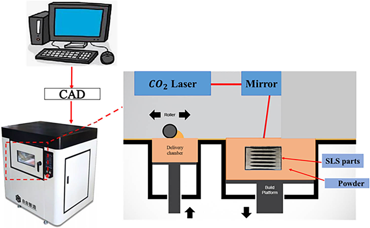
The structure of SLS machine characteristic process.
2.4 Density
The density of PSPC SLS samples, manufactured under different SLS parameters, was calculated by measuring their dimensions and weights using precise instruments. The density calculation method for various PSPC parts involved samples each designed to have nominal dimensions of 80 × 13 × 4 mm. Each PSPC part underwent triplicate testing for density assessment, and the mean values from these tests were reported as the final results to ensure accuracy and reliability. The results of these density experiments are presented in Tables 3–7. Furthermore, the density of PSPC SLS samples was calculated using Eq. (1).
where D denotes the density (g·cm−3), s represents the length of sample (mm), W represents the width of sample (mm), T is the thickness of sample (mm), and m is the mass/weight of produced PSPC specimens (g).
2.5 DP
The DP of PSPC SLS samples, manufactured under various SLS parameters, was calculated by measuring their dimensions. The DP calculation method for various PSPC parts involved samples each designed to have nominal dimensions of 80 × 13 × 4 mm. Using a sensitive Vernier device, the actual dimensions in terms of length, width, and thickness were carefully measured. This analysis, along with other parameters, enabled us to pinpoint the optimal SLS parameters. The DP of various PSPC parts was determined using Eq. (2). To ensure accuracy and reliability of DP testing, each part underwent triplicate tests, with the mean values reported as the final results.
where d represents the official measured dimension size (mm) of the PSPC SLS piece; d 1 (%) denotes the DP (%); and d o signifies the standard specified dimension (mm) of the parts.
2.6 SEM analysis
The surface morphology and particle size of PES powders and PSP were visualized using the FEI Quanta 200 SEM device (Figure 4). This test also examined the inner morphology, particle distribution and microstructure of SLS PSPC parts manufactured under various SLS processing conditions, such as changes in preheating temperature, laser power, scan speed, scan spacing, and layer thickness. SEM tests support the mechanical analysis department by providing insights into particle bonding, a crucial factor influencing mechanical strength of the produced SLS parts. The bonding and connecting between PSPC particles is influenced by various SLS parameters (Table 1). PSPC samples manufactured under various SLS parameters were analyzed using both SEM tests and mechanical tests to further investigate the influence of SLS parameters on their mechanical performance. To confirm these findings, SEM analysis was conducted on 17 samples to assess bonding strength and scientifically validate the results obtained from mechanical experiments.

SEM surface morphology of (a) pure PSP and (b) pure PES powder.
2.7 Thermal physical properties test of PSP and PES
Thermophysical tests enable the comprehensive characterization of biomass powders, aiding in understanding material thermal behavior and optimizing parameters for suitable material design and product quality assurance. Common thermal tests include:
Thermogravimetric analysis (TGA): TGA measures the weight changes of a material as a function of temperature or time under controlled heating conditions in an inert atmosphere. For biomass powders, TGA helps determine the decomposition behavior, moisture content, thermal stability, and volatile matter content. It provides insights into the thermal degradation kinetics and pyrolysis characteristics of biomass, which are crucial for understanding its combustion and gasification behavior.
Differential scanning calorimetry (DSC): DSC measures the heat flow into or out of a sample as a function of temperature or time. It helps identify phase transitions, such as melting, crystallization, glass transitions, and chemical reactions occurring in the biomass powder. In the case of biomass, DSC can provide information about the thermal properties, including specific heat capacity, thermal conductivity, and enthalpy changes associated with different thermal events. Understanding the energy storage and release mechanisms during processes like combustion and pyrolysis of biomass powders is crucial. The various thermal combination tests conducted aim to provide insights into these mechanisms. The ultimate goal is to leverage this information to improve the mechanical properties of biomass composite powders. By addressing issues related to low mechanical quality in wood-plastic products, these efforts contribute to enhance the overall performance and reliability of such materials in various applications.
In this study, the DSC device was used to determine the glass transition temperatures (Tg) of both PSP and pure PES powders. For each test, 5 mg samples of PSP and PES were prepared for both DSC and TGA analyses. The testing parameters included a heating rate of 10°C·min−1, with the DSC test conducted between 20 and 240°C, and the TGA test between 100 and 600°C. The DSC and TGA results were used to estimate the primary temperature ranges. Figure 5 shows the TGA (a) and DSC (b) curves for PES and PSP, respectively.
Thermal conductivity: This test measures the ability of biomass powders to conduct heat. The thermal conductivity of PES powder was found to be 0.21 W·m·K−1, while PSP had a thermal conductivity of 0.14 W·m·K−1.
Specific heat capacity (J·g·K−1): The specific heat capacity test results provide essential information about the heat storage properties of different biomass powders, which is crucial for determining their suitability for various thermal applications. The specific heat capacity of PES was 1.1 J·g·K−1, and for PSP, it was 1.6 J·g·K−1.
Density: The density test determines the mass per unit volume of the biomass powder, which is crucial for various thermal calculations. The density of PES and PSP powders was measured to be 1.37 and 0.60 g·cm−³, respectively.

Thermal properties tests: (a) Thermogravimetric analysis (TGA) test curves of PSP and PES powders. (b) Differential scanning calorimetry (DSC) test curves of PSP and PES powders.
2.8 Mechanical testing
Mechanical strength evaluations, including bending and tensile properties were conducted on various PSPC samples using a Byes-3003 testing machine. Each PSPC part underwent triplicate testing for mechanical strength assessment, and the mean values from these tests were reported as the final results. Impact strength was determined via Charpy impact testing, adhering to ISO 179-2000 Chinese standards. Statistical analyses, including a 95% confidence interval, were applied to the calculated mechanical strengths values to enhance the reliability of the test results. Tensile specimens were fabricated in compliance with Chinese standards (GB/T 9341-2008), with dimensions of 150 × 20 × 10 mm, while bending specimens adhered to GB/T 9341-2008 standards, measuring 80 × 13 × 4 mm.
Impact specimens were manufactured following ISO 179-2000 standards, with dimensions of 80 × 10 × 4 mm. Figure 6(a)–(e) showcases PSPC SLS specimens produced utilizing parameters outlined in Table 1 and illustrates the mechanical testing process employing a universal testing machine.

Photographs of PSPC SLS specimens utilized for mechanical testing (a) a tensile specimen under testing, (b) 16 groups of PSPC SLS samples of the orthogonal experimental of tensile strength test, (c) a bending specimen under testing, (d) 16 groups of PSPC SLS samples of the orthogonal experimental of bending strength test, and (e) the universal testing machine.
2.9 Surface roughness analysis of PSPC parts
Surface roughness testing is vital for evaluating biomass composite materials’ quality and performance. It aims to quantify irregularities and variations in the upper surface of biomass composite parts, providing essential data for assessing finish, upper surface quality, and suitability for specific applications. Various methods, including contact and non-contact techniques, can be used to measure the surface roughness. Parameters such as Ra, Rz, Rq, and Rt characterize surface roughness, quantifying the distribution of irregularities. Measurements are typically taken at multiple locations to ensure representative data across specified areas.
Data from the surface roughness measurements are analyzed to evaluate the quality of surface finish. Deviations from desired characteristics may indicate defects, inconsistencies, or the need for treatment. Surface roughness significantly influences functional properties like friction, adhesion, wear resistance, and aesthetics, crucial for material performance. Understanding surface roughness is crucial for optimizing the performance and durability of biomass composite materials in diverse applications. Surface roughness testing holds significant value across various industries by ensuring product quality and performance. In this study, the surface quality of PSPC SLS parts, including surface appearance and features, was evaluated using surface roughness testing. Each part underwent triplicate testing, with the mean values reported as final results. These mean values, depicted in Tables 3–7, provide insights into surface characteristics, aiding in optimizing product quality and performance.
2.10 Effect of material ratio on the structure of laser sintering parts
To assess the influence of various SLS processing parameters on the mechanical performance of PSPC SLS parts, first it is essential to determine the optimal powder mixture ratio for PSPC. Therefore, five different composite ratios of PSPC were selected and thoroughly studied to identify the most suitable ratio for future applications of PSPC. The determination of the best PSPC powder mixture ratio involved the use of specific SLS parameters, including a preheating temperature of 78°C, laser power set at 16 W, scanning speed at 1.8 m·s−1, scanning spacing of 0.12 mm, and layer thickness of 0.2 mm. Under these process conditions, the impact of the added amount of PSP on the density and mechanical properties of PSPC SLS sintered parts is presented in Table 2.
Density and mechanical properties of SLS PSPC parts with different mass ratios
| PS powder content (%) | Density (g·cm−3) | Tensile strength (MPa) | Elongation at break (%) | Bending strength (MPa) | Impact strength (kJ·cm−2) | DP (%) | ||
|---|---|---|---|---|---|---|---|---|
| X | Y | Z | ||||||
| 0 | 0.924 | 4.5 | 16.32 | 8.4 | 1.51 | 99.88 | 99.42 | 91.015 |
| 5 | 0.942 | 4.79 | 17.1 | 8.95 | 1.76 | 99.94 | 99.85 | 96.76 |
| 10 | 1.2 | 6.1 | 18.45 | 14.1 | 2.12 | 99.99 | 99.97 | 98.84 |
| 15 | 0.945 | 4.85 | 17.88 | 12 | 1.87 | 99.96 | 99.92 | 97.56 |
| 20 | 0.89 | 3.95 | 14.78 | 7.88 | 1.16 | 98.67 | 97.82 | 88.78 |
According to the data in Table 2, as the proportion of PSP increases from 0 to 20%, the density of PSPC parts decreases from 0.924 to 0.89 g·cm−3, resulting in low mechanical properties. Adding 5% PSP to raw natural PES increases tensile strength from 4.5 to 4.79 MPa, elongation at break from 16.32 to 17.1%, and bending strength from 8.4 to 8.9 MPa. Notably, increasing the PSP content to 10% significantly improves the mechanical properties of PSPC SLS parts, with enhanced elongation at break and bending strength. This improvement is attributed to the enhanced bonding strength between particles, facilitating the full melting of PES. Acting as both a matrix material and a binder, PES increases the sintering neck between particles. The increase in mechanical properties may also be influenced by the opposing chemical polarity of PSP and PES, resulting in poor interface compatibility and weak bonding strength, which affects the overall mechanical strength of SLS pieces. Additionally, the degree of DP of PSPC SLS parts is influenced by the addition of PSP, as outlined in Table 2. Initially, the DP of PSPC parts increases with the addition of PSP, but it subsequently decreases with further additions. This is because PSP provides structural support during the SLS processing, reducing the degree of deformation caused by the melting and cooling process of the powder composite.
A comprehensive comparison of PSPC mixed powder revealed that SLS parts containing 10% PSP exhibit favorable mechanical strength and good DP. Therefore, PSPC with 10% PSP was selected for subsequent SLS process parameter optimization research. Conversely, when the PSP content increased to 15 and 20%, the mechanical properties of PSPC SLS parts notably declined. Parts containing 10% PSP demonstrated improved elongation at break, superior bending strength, and better DP in the X, Y, and Z directions. The reduction in mechanical properties with higher PSP content can be attributed to a decrease in bonding strength between PSP and PES powders. The inadequate interface compatibility between the two powders results in weak bonding strength, adversely affecting the mechanical integrity of PSPC SLS parts.
3 Results and discussion
3.1 Analysis of mechanical properties of PSPC
Mechanical property analysis is crucial on the engineering applications such as manufacturing, construction, and materials science. It enables researchers to understand the material behavior under different conditions, optimizing designs for improved performance and ensuring compliance with safety standards. By understanding material behavior in varied scenarios, it facilitates the refinement of designs for enhanced performance, durability, and safety adherence, essential in engineering endeavors. Therefore, assessing the mechanical performance of PSPC SLS pieces was essential to comprehend the effect of SLS processing parameters on various aspects like density, DP, surface roughness, bending, tensile, and impact strengths. These test results offer insights into how SLS parameters affect the mechanical properties of PSPC SLS parts. Photographs of the PSPC SLS specimens used for mechanical tests are depicted in Figure 6.
3.2 Assessing the influence of preheating temperature on the mechanical performance of PSPC SLS parts
The study centered on SLS process, which involved utilizing a CO2 laser beam to impart heat energy to PSPC. Nevertheless, fluctuations in variations in laser energy absorption efficiency influenced heat transfer efficacy, consequently influencing several characteristics of the PSPC sintered parts. These attributes included mechanical strength, such as impact, bending, and tensile strengths as well as density, DP, and surface roughness.
The PSPC test specimens were fabricated with specific parameters, including a scan spacing of 0.12 mm, a scan speed of 1.8 m·s−1, a laser power of 16 W, and a layer thickness of 0.2 mm. Furthermore, the PSP particle size was selected to be less than 125 (µm), with a consistent mixture ratio of 10/90 (%). To assess the influence of the heating rate temperature on the PSPC SLS parts mechanical performance, four levels of preheating temperature were selected: 74, 76, 78, and 80°C, to produce the test samples. The corresponding results of surface roughness, bending experiments, tensile experiments, impact experiments, density experiments, and DP assessments at several heating temperatures are shown in (Table 3 and Figure 7).
Repeated mechanical performance tests conducted on PSPC SLS parts manufactured at various preheating temperatures. The data include the upper and lower limits of their 95% confidence interval for the mean of impact, bending, and tensile strengths, as well as density and surface roughness
| T (°C) | Bending strength (MPa) | Tensile strength (MPa) | Impact strength (kJ·cm−2) | Density (g·cm−3) | Surface roughness (µm) | ||||||||||
|---|---|---|---|---|---|---|---|---|---|---|---|---|---|---|---|
| Rep tests | Mean | Rep tests | Mean | Rep tests | Mean | Rep tests | Mean | Rep tests | Mean | ||||||
| 74 | 11.5 | 11.43 | Lower = 11.1464898 | 4.79 | 4.86 | Lower = 4.676885 | 1.74 | 1.71 | Lower = 1.644275894 | 0.84 | 0.9 | Lower = 0.768551788 | 4.89 | 4.93 | Lower = 4.778895802 |
| 11.3 | 4.94 | 1.69 | 0.94 | 5 | |||||||||||
| 11.5 | Upper = 11.7201768 | 4.86 | Upper = 5.0497816 | 1.70 | Upper = 1.7757241 | 0.92 | Upper = 1.0314482 | 4.9 | Upper = 5.08110419 | ||||||
| 76 | 11.96 | 12.2 | Lower = 11.25211346 | 5 | 5.12 | Lower = 4.851299423 | 1.91 | 1.88 | Lower = 1.659205011 | 0.9 | 0.94 | Lower = 0.808551788 | 5.75 | 5.81 | Lower = 5.676517696 |
| 12 | Upper = 13.14788654 | 5.21 | Upper = 5.38870058 | 1.95 | Upper = 2.100794989 | 0.92 | Upper = 1.071448212 | 5.84 | Upper = 5.95014897 | ||||||
| 12.64 | 5.15 | 1.78 | 1 | 5.85 | |||||||||||
| 78 | 14.22 | 14.1 | Lower = 13.59736795 | 5.98 | 6.1 | Lower = 5.615067024 | 2.25 | 2.12 | Lower = 1.808738437 | 0.98 | 1.2 | Lower = 0.68009197 | 5.89 | 5.93 | Lower = 5.778895802 |
| 13.87 | Upper = 14.61596539 | 6.33 | Upper = 6.591599642 | 2 | Upper = 2.431261563 | 1.24 | Upper = 1.733241364 | 6 | Upper = 6.081104198 | ||||||
| 14.23 | 6 | 2.11 | 1.4 | 5.90 | |||||||||||
| 80 | 15.87 | 15.2 | Lower = 13.81091394 | 7 | 6.54 | Lower = 5.513356644 | 2.36 | 2.32 | Lower = 2.125982642 | 1.4 | 1.4 | Lower = 0.406344915 | 7.75 | 7.74 | Lower = 7.715158623 |
| 14.88 | Upper = 16.62242 | 6.2 | Upper = 7.566643 | 2.23 | Upper = 2.5140174 | 1.8 | Upper = 2.3936551 | 7.74 | Upper = 7.76484138 | ||||||
| 14.9 | 6.42 | 2.37 | 1 | 7.73 | |||||||||||

The effect of various SLS parameters on the DP of PSPC SLS parts manufactured under various SLS: (a) Heating temperature, (b) laser power, (c) scan speed, (d) scan spacing, and (e) layer thickness. Error bars are included to indicate variability in the results, providing insights into the mechanical performance of the manufactured parts under different processing conditions.
The increase in heating temperature directly led to enhance the energy absorption of the PSPC due to rise in the amount of energy absorbed, increasing its heat transfer efficiency. This enhancement is evidenced in SEM analysis (Figure 8(a)), which reveals a substantial improvement in interfacial bonding, internal formation, and the size volume of sintered neck between PSP and PES powders as the preheating temperature of PSPC increases. Consequently, this led to a clear improvement in density and mechanical strengths of PSPC SLS pieces (Table 3). The enhancement in interfacial bonding strength and sintered neck formation led to a decrease in porosity within the PSPC parts. However, there was a slight reduction in DP (Figure 7(a)) and surface roughness quality of the PSPC pieces observed concurrently with an increase in preheating temperature (Table 3). This decrease can be attributed to the shrinkage of the parts and the occurrence of agglomeration on the upper surface of the samples Figure 8(a). These effects were associated with the increased interfacial bonding strength and density in PSPC parts due to higher temperatures.

This figure displays the SEM morphology of the PSPC parts produced under different SLS processing conditions, including variations in preheating temperature, laser power, scan speed, scan spacing, and layer thickness, as shown in (a) to (l), respectively.
When the optimal preheating temperature of 78°C was utilized, the PSPC SLS parts demonstrated the most favorable balance between mechanical strength, DP, and surface roughness. At this temperature, the sintering neck was well-formed, and the upper surface appeared smoother (Figure 8(b)). Consequently, the PSPC SLS part manufactured at a temperature of 78°C exhibited excellent mechanical properties, with bending strength of 14.1 MPa, tensile strength of 6.1 MPa, impact strength of 2.12 kJ·cm−2, and a density of 1.2 g·cm−3, respectively (Table 3). Experimental results also revealed outstanding DP and surface roughness in all directions, with values of 99.99, 99.97, and 98.84% for X, Y, and Z directions, respectively. However, at 80°C, although the PSPC sintered part showed higher mechanical strength (Table 3), it unfortunately caused deformation on the side surfaces, leading to a decline in DP quality (Figure 7(a)) and surface roughness values for PSPC SLS pieces (Table 3).
Therefore, as the heating temperature of the PSPC increased from 76 to 78°C, the bending strength of SLS piece demonstrated a maximum rise of 2 MPa from 12.2 to 14.1 MPa. Similarly, tensile, impact strengths, and density of PSPC sintered part showed their maximum increases of 0.98 MPa (from 5.12 to 6.1 MPa), 0.24 kJ·m−2 (from 1.88 to 2.12 kJ·m−2), and 0.26 g·cm−3 (from 0.94 to 1.2 g·cm−3), respectively, within the same temperature range.
As the heating temperature raised continuously, it eventually reached the hardening temperature of the PSPC piece, causing unsintered powder to adhere to PSPC SLS piece. This adhered powder is not easily removed from the PSPC SLS piece, leading to an increase in the dimensions of PSPC SLS piece in all directions due to the presence of adhered powders. Consequently, the surface roughness and DP of the PSPC SLS piece shows a contrary correlation with the preheating temperature, decreasing as the preheating temperature increased (Table 3 and Figure 7(a)).
Conversely, reduced heating temperatures lead to decreased heat transfer efficiency during the heating process, consequently resulting in lower density, impact, bending, and tensile strengths of the PSPC SLS pieces, as evident from the effects observed at low preheating temperatures. This decrease was due to a reduction in the bonding strength between powder particles, as well as an increase in the size of porosity inside PSPC SLS piece (Figure 8(c)). A comparison was made between the mechanical strengths, density, and DP of PSPC SLS pieces manufactured at different heating temperatures. This comparison aimed to identify the optimal preheating temperature that would optimize the mechanical strengths, surface roughness, and DP of PSPC SLS pieces. The conclusion drawn from the comparison emphasized the importance of selecting an appropriate preheating temperature in SLS to achieve PSPC SLS pieces with excellent mechanical strengths and DP, along with low surface roughness.
All measured mechanical properties, including bending, tensile, and impact strengths, along with density and surface roughness, were subjected to confidence testing. The results demonstrated that all measured values fell within the 95% confidence interval, i.e., within their upper and lower limits, underscoring the reliability and dependability of the experimental results (Table 3).
3.3 Assessing the effect of the laser power on the mechanical performance of PSPC SLS pieces
The SLS process technology functions by directing a laser beam onto a focused spot, traversing the forming surface of the PSPC parts, thereby forming sintered PSPC parts, as evidenced in this study. The laser power is influenced via the distribution of light intensity within the laser beam, a factor determined by Eq. (4).
where w is the characteristic radius (mm), h is the light intensity of the laser beam, l is the laser power (w), v is the distance between the inspection point and the spot center (mm). The specific parameters for fabricating the PSPC test specimens included a scan spacing of 0.12 mm, a scan speed of 1.8 m·s−1, a preheating temperature of 78°C, and a layer thickness of 0.2 mm, respectively. Besides, the PSP particle size ≤ 125 µm, with consistent mixture ratio of 10/90%. To assess the impact of laser power on the mechanical performance of PSPC SLS pieces, the laser power for producing the four test samples of PSPC was set at four levels according to experimental design (Table 1), i.e., 10 W, 12 W, 14 W, and 16 W, respectively. Tests samples were produced under these four different levels of laser power; subsequently, the mechanical properties of PSPC parts manufactured at these laser power levels were assessed.
The findings of the surface roughness test, impact, bending, tensile, and density tests along with the DP tests measurements are presented in Table 4 and (Figure 7(b)), respectively. Typically, as the laser power increases, the PSPC absorbs more energy. Consequently, there is an escalation in the energy diffused along the sintering path of laser, resulting in higher density of PSPC SLS part. This increase in density is attributed to a greater sintering depth and an enlargement of the sintered-neck between PSP and PES particles, which leads to a reduction in the size volume of inner holes within PSPC piece, as illustrated in Figure 8(d). Consequently, the impact, bending, and tensile strengths, along with the density of PSPC SLS pieces, exhibit an increase (Table 4) with higher laser power, attributed to the enhanced sintered neck formation between PSP and PES particles (Figure 8(d)). However, an increase in laser power resulted in a decrease in DP (Figure 7(b)) and decrease in the quality of surface roughness (Table 4). This reduction in quality of DP and surface roughness is attributed to the greater sintering depth, leading to increased shrinkage of the PSPC parts and the occurrence of agglomeration on the upper surface of the samples (Figure 8(d)). The results indicate that the PSPC SLS part manufactured at a laser power of 16 W showed maximum strengths, with bending strength of 14.1 MPa, tensile strength of 6.1 MPa, and impact strength of 2.12 kJ·m−2, along with a density of 1.2 g·cm−3 (Table 4). Additionally, at this laser power, the part displayed excellent DP values of 99.99, 99.97, and 98.84% for X, Y, and Z directions, respectively, along with a surface roughness of 5.93 µm. Reducing the laser power from 16 W to 14 W resulted in a decrease in bending, tensile, and impact strengths, along with density, to 13.05 MPa, 5.43 MPa, 1.58 kJ·m−2, and 0.94 g·cm−3, respectively. Besides, tensile and bending strengths of the PSPC SLS piece showed a maximum reduction of 0.7 MPa (from 6.1 to 5.43 MPa) and 1.05 MPa (from 14.1 to 13.05 MPa), respectively, with a reduction in laser power from 16 to 14 W due to decrease in the energy absorbed by PSPC. Moreover, with the reduction in laser power, there is a reduction in the sintering depth and size volume of sintered neck between PSPC particles. This led to decreased shrinkage of the parts and the occurrence of agglomeration on the upper surface of the PSPC samples, as illustrated in Figure 8(e). Consequently, the reduction in laser power lead to a decrease in the density of PSPC SLS pieces, thereby leading to the decline in mechanical strength. However, the DP and surface roughness of the PSPC SLS pieces improved with a reduction in laser power. This improvement can be attributed to decreased shrinkage and a reduction in the occurrence of agglomeration on the upper surface of the PSPC samples.
Repeated mechanical performance tests conducted on PSPC SLS parts manufactured at various laser power. The data include the upper and lower limits of their 95% confidence interval for the mean of impact, tensile, and bending strengths, along with density and surface roughness
| Laser power (w) | Bending strength (MPa) | Tensile strength (MPa) | Impact strength (kJ·cm−2) | Density (g·cm−3) | Surface roughness (µm) | ||||||||||
|---|---|---|---|---|---|---|---|---|---|---|---|---|---|---|---|
| Rep tests | Mean | Rep test | Mean | Rep tests | Mean | Rep tests | Mean | Rep tests | Mean | ||||||
| 10 | 11.43 | 11.21 | Lower = 10.59263021 | 4.13 | 4 | Lower = 2.714713774 | 0.7 | 0.72 | Lower = 0.443378132 | 0.49 | 0.54 | Lower = 0.426162509 | 4.36 | 4.26 | Lower = 4.014505884 |
| 10.94 | Upper = 11.83403645 | 4.44 | Upper = 5.285286226 | 0.62 | Upper = 0.996621868 | 0.58 | Upper = 0.653837491 | 4.16 | Upper = 4.512160783 | ||||||
| 11.27 | 3.43 | 0.84 | 0.55 | 4.27 | |||||||||||
| 12 | 12.1 | 12.1 | Lower = 11.51951693 | 4.55 | 4.75 | Lower = 4.31332844 | 1.0 | 1.12 | Lower = 0.560103795 | 0.81 | 0.73 | Lower = 0.542451716 | 4.66 | 4.83 | Lower = 4.41078645 |
| 12.34 | Upper = 12.68714974 | 4.88 | Upper = 5.18667156 | 0.98 | Upper = 1.679896205 | 0.66 | Upper = 0.917548284 | 5.0 | Upper = 5.255880217 | ||||||
| 11.87 | 4.82 | 1.38 | 0.72 | 4.84 | |||||||||||
| 14 | 12.83 | 13.05 | Lower = 11.9607833 | 5.5 | 5.43 | Lower = 4.916218832 | 1.0 | 1.58 | Lower = 1.096332511 | 1.0 | 0.94 | Lower = 0.777104197 | 5.43 | 5.43 | Lower = 4.675637396 |
| 12.77 | Upper = 14.14588334 | 5.6 | Upper = 5.950447835 | 0.98 | Upper = 2.070334155 | 0.87 | Upper = 1.102895803 | 5.74 | Upper = 6.191029271 | ||||||
| 13.56 | 5.2 | 1.38 | 0.95 | 5.13 | |||||||||||
| 16 | 14.22 | 14.1 | Lower = 13.59736795 | 5.98 | 6.1 | Lower = 5.615067024 | 2.25 | 2.12 | Lower = 1.808738437 | 0.98 | 1.2 | Lower = 0.68009197 | 5.89 | 5.93 | Lower = 5.778895802 |
| 13.87 | Upper = 14.61596539 | 6.33 | Upper = 6.591599642 | 2.0 | Upper = 2.431261563 | 1.24 | Upper = 1.733241364 | 6.0 | Upper = 6.081104198 | ||||||
| 14.23 | 6.0 | 2.11 | 1.4 | 5.90 | |||||||||||
Insufficient intensity and density of the laser beam at low laser power levels led to inadequate energy absorption by the PSPC and incomplete melting of the PES powder. As a result, this led to the weakening of the sintered neck between the PSP and PES powders, along with an enlargement and increase in the size of porosity within the PSPC SLS parts, as shown in Figure 8(f). Consequently, the mechanical strengths along with density of PSPC SLS pieces, decreased with decreasing laser power (Table 4). Conversely, DP and surface roughness showed a little improvement with reduced laser power (Figure 7(b) and Table 4).
The correlation between the mechanical strength, DP, and surface quality reveals an inconsistency: while mechanical strength tends to increase with higher laser power, DP and surface roughness quality decrease. This highlights the necessity of selecting an optimal laser power value that enhances mechanical strength while maintaining excellent DP and good surface roughness quality. This underscores the importance of optimizing laser power to manufacture PSPC SLS pieces with superior mechanical strength, high DP, and excellent surface quality. Furthermore, a comparison was made between the mechanical strength of PSPC SLS pieces and those of sisal fiber powder composite (SFPC) and pure PES SLS pieces, all manufactured under identical processing parameters (Figure 9). This comparison unveiled that the mechanical strengths and DP of the PSPC SLS pieces surpassed those of SFPC, PCPC pieces and pure PES SLS pieces. All measured mechanical properties, including mechanical strengths, density, and surface roughness, underwent reliability assessment through confidence testing. The results demonstrated that all measured values fell within the 95% confidence interval, indicating the reliability and dependability of the results as they aligned with both their upper and lower limits (Table 4).

Comparison of mechanical properties between various biomass composite materials.
3.4 Assessing the effect of scanning speed on the mechanical performance of PSPC SLS pieces
The scanning speed in SLS refers to the rate at which the laser beam moves across the powder bed during the sintering process. It is a critical parameter that influences the overall build time, which is affect resolution, and quality of the PSPC printed parts in an SLS system. The scanning speed is typically measured in units such as millimeters per second (mm·s−1) and represents how quickly the laser traces the desired pattern or cross-section of the 3D object being printed. Modifying the scanning speed range will influence the sintering process, influencing factors such as heat distribution and powder melting, thereby affecting the mechanical properties of PSPC SLS parts. Moreover, within the SLS system, scanning speed refers to the distance and space traversed by the scanning laser beam over a set duration. The influence of scanning speed on the mechanical properties of PSPC SLS components is assessed by examining the cross-sectional energy density of the laser scanning line. This involved utilizing Eq. (5) to ascertain the energy density distribution within the laser scanning line.
where Y is the energy density (J·mm−3), e is the distance between the spot center and inspection point (mm), V is the laser power (W), r is the radius (mm), and s is the scanning speed (mm·s−1).
The specific parameters for fabricating the PSPC test specimens included a scan spacing of 0.12 mm, a laser power of 16, a preheating temperature of 78°C, and a layer thickness of 0.2 mm. Additionally, the PSP particle size was chosen to be fewer than 125 µm, with a consistent mixture ratio of 10/90%. To evaluate the influence of scanning speed on mechanical characteristics of PSPC SLS pieces, four different levels of scanning speed were established according to the experimental design (Table 1): 1.4, 1.6, 1.8, and 2 m·s−1, respectively. Test samples were then fabricated at these specified scanning speeds. Following this, the mechanical properties of PSPC SLS pieces manufactured on each scanning speed level were analyzed.
The findings of the DP measurements, impact strength tests, tensile strength tests, bending strength tests, surface roughness, and density evaluated are depicted in (Figure 7(c)) and Table 5. The data in Table 5 indicate a direct correlation between increased scanning speed and a decrease in mechanical strengths and density. This phenomenon can be attributed to the shorter duration of laser heat exposure on PSPC at higher scanning speeds in SLS, resulting in a decrease in the energy density along the laser scanning line. Therefore, as the scanning speed of SLS increases, PSPC absorbs insufficient energy, resulting in incomplete melting of the powder. This incomplete melting leads to decreased mechanical strengths and density of PSPC SLS pieces, which are directly caused by increased porosity between PSP and PES particles, stemming from a reduction in interfacial bonding strength (Figure 8(g)). Hence, the mechanical strength of the PSPC SLS pieces reduced as the scanning speed increased attributed to reduced processing time required for SLS in PSPC pieces. PSPC SLS parts fabricated at a laser scanning speed of 1.4 m·s−1 showed a maximum mechanical strength (Table 5) owing to reduced pores within PSPC powder particles and increased bonding strengths (Figure 8(h)). The minimal pores in PSPC SLS parts resulted from the full melting of PES particles, facilitating better bonding between PSPC particles, a phenomenon observed at lower scanning speeds.
Repeated mechanical performance tests for PSPC SLS pieces at different scanning speeds. The data include the upper and lower limits of the 95% confidence interval for the mean of bending, tensile, and impact strengths, as well as density and surface roughness
| Scanning speed (m·s−1) | Bending strength (MPa) | Tensile strength (MPa) | Impact strength (kJ·cm−2) | Density (g·cm−3) | Surface roughness (µm) | ||||||||||
|---|---|---|---|---|---|---|---|---|---|---|---|---|---|---|---|
| Rep tests | Mean | Rep test | Mean | Rep tests | Mean | Rep tests | Mean | Rep tests | Mean | ||||||
| 1.4 | 14.91 | 15 | Lower = 14.60655709 | 7.71 | 7.55 | Lower = 7.164358122 | 2.86 | 2.8 | Lower = 2.214248966 | 1.81 | 1.73 | Lower = 1.5561104 | 8.58 | 8.64 | Lower = 8.481705221 |
| 5.21 | Upper = 15.43344291 | 7.40 | Upper = 7.935641878 | 3 | Upper = 3.385751034 | 1.68 | Upper = 1.90388964 | 8.71 | Upper = 8.804961446 | ||||||
| 14.95 | 7.54 | 2.54 | 1.7 | 8.64 | |||||||||||
| 1.6 | 14.8 | 14.87 | Lower = 14.48173256 | 6.417 | 6.67 | Lower = 5.921866139 | 2.54 | 2.73 | Lower = 2.306237851 | 1.3 | 1.55 | Lower = 0.7743283 | 6.69 | 6.51 | Lower = 5.840203501 |
| 14.72 | Upper = 15.19826744 | 6.6 | Upper = 7.418133861 | 2.87 | Upper = 3.153762149 | 1.9 | Upper = 2.325671752 | 6.20 | Upper = 7.179796499 | ||||||
| 15 | 2.78 | 1.45 | 6.64 | ||||||||||||
| 1.8 | 14.22 | 14.1 | Lower = 13.59736795 | 5.98 | 6.1 | Lower = 5.615067024 | 2.25 | 2.12 | Lower = 1.808738437 | 0.98 | 1.2 | Lower = 0.68009197 | 5.89 | 5.93 | Lower = 5.778895802 |
| 13.87 | Upper = 14.61596539 | 6.33 | Upper = 6.591599642 | 2 | Upper = 2.431261563 | 1.24 | Upper = 1.733241364 | 6 | Upper = 6.081104198 | ||||||
| 14.23 | 6 | 2.11 | 1.4 | 5.90 | |||||||||||
| 2 | 13.75 | 13.45 | Lower = 12.32690598 | 5.5 | 5.45 | Lower = 4.978013835 | 1.51 | 1.69 | Lower = 1.020203501 | 0.91 | 0.78 | Lower = 0.487124483 | 4.89 | 4.69 | Lower = 4.234650036 |
| 12.93 | Upper = 14.57309402 | 5.24 | Upper = 5.921986165 | 2 | Upper = 2.359796499 | 0.68 | Upper = 1.072875517 | 4.65 | Upper = 5.145349964 | ||||||
| 13.67 | 5.61 | 1.56 | 0.75 | 4.53 | |||||||||||
Consequently, the bending strength was 15 MPa, tensile strength was 7.55 MPa, impact strength was 2.8 kJ·m−2, and density was 1.73 g·cm−3. However, the surface roughness and DP quality were decreased directly in low scanning speed. As the scanning speed escalated from 1.6 to 1.8 m·s−1, there was a notable decline in the bending strength, tensile strength, and impact strength of the sintered parts. Specifically, these values decreased by 0.77 MPa, 0.57 MPa, and 0.61 kJ·m−2, respectively. Elevating the scanning speed to 2 m·s−1 led to a more pronounced decrease in bending strength, with a decline of 0.65 MPa. Conversely, the DP and surface roughness of the PSPC SLS pieces exhibited improvement with the increased scanning speed, attributed to the reduction in sintering depth (Table 5).
Reducing the laser scanning speed extended the processing duration of laser sintering, thereby augmenting the cross-sectional energy density of the laser scanning line. This facilitated improved heat transfer efficiency during sintering, consequently increasing the density by minimizing internal pores between PSPC particles. Consequently, the bending, tensile, impact strengths, and density of the SLS PSPC exhibited gradual and continuing increments with decreasing scanning speed (Table 5). The mechanical properties data presented in Table 5 revealed a negative correlation between the laser beam scanning speed and the bending, tensile, and impact strengths, as well as density, while demonstrating a positive relationship with the DP and surface roughness of the PSPC SLS pieces.
The relationship between mechanical strengths, DP, and surface quality highlights an inconsistency: while mechanical strength tends to decrease with higher scanning speed, DP, and surface roughness quality increase. This underscores the importance of selecting an optimal scanning speed value that enhances mechanical strength while maintaining excellent DP and surface roughness quality. It was decided that a best scanning speed was necessary to manufacture PSPC SLS pieces with great excellent mechanical strengths and great DP and superior surface roughness. Therefore, PSPC parts manufactured at a scan speed of 1.8 m·s−1 showed a positive relationship between mechanical strength, DP, and surface roughness quality. Thus, PSPC SLS pieces produced at 1.8 m·s−1 have the potential for application in AM technology, particularly in various wood-manufacturing operations due to their good mechanical strength as well as excellent DP and surface roughness quality. All measured mechanical properties, including bending, tensile, and impact strengths along with density, surface roughness, and DP in all directions, underwent confidence testing to assess their reliability. The results showed that all measured values fell within the 95% confidence interval, affirming the reliability of the results, as they remained consistent with both their upper and lower limits (Table 5).
3.5 Assessing the influence of scan spacing (mm) on the mechanical performance of PSPC SLS parts
The scan spacing refers to the distance between successive scan lines of laser beam during the printing process. It is an essential parameter that influences the laser forming on powder composite as well as the mechanical properties of the printed parts. Experimentally, scan spacing, alternatively known as hatch spacing or hatch distance, refers to the separation between two consecutive laser beams. It is measured as the distance from the center of one beam to the center of the next beam. Scan spacing is directly proportional to production speed in SLS processing and significantly impacts the quality of the resulting SLS parts. Therefore, studying and evaluating the effect of laser scan spacing on the mechanical properties of PSPC parts is crucial.
The PSPC specimens were produced with specific parameters: the laser power, preheating temperature, layer thickness, and scanning speed were set to 16 W, 78°C, 0.2 mm, and 1.8 m·s−1, respectively. Additionally, the PSP particle size was selected to be less than 125 µm, with a consistent mixture ratio of 10/90%. To evaluate the influence of scanning spacing on mechanical properties of PSPC SLS pieces, four different levels of scanning spacing were selected according to the experimental design (Table 1): 0.12, 0.16, 0.2, and 0.24 mm, respectively. Test samples were then fabricated at these specified scanning spacing. Following this, the mechanical properties of PSPC SLS pieces manufactured on each scanning spacing level were analyzed.
The test results for mechanical properties, including DP, surface roughness, impact, tensile, bending, tests, and density measurements, are detailed in Table 6 and illustrated in Figure 7(d). Increasing the laser scan spacing throughout SLS reduces the sintering area, leading to a decrease in the energy absorbed by the PSPC. The raised scan spacing hindered the full melting of the PSPC, resulting in a decline in bonding interfacial strength between PSP and PES matrix (Figure 8(j)). Moreover, incomplete melting of the PSPC resulted from the decreased sintering area, causing an increase in the sizes of the inner holes within the produced PSPC SLS pieces (Figure 8(j)). Consequently, the mechanical strengths of PSPC SLS pieces exhibited a decline with the increase in scan spacing, as indicated in Table 6. Conversely, with a smaller scan spacing, the laser beam makes a greater number of runs on the PSPC, exposing the powder to a higher amount of energy. This positively affects the bonding interface between PSP and PES powder particles, reducing pores between PSPC SLS pieces (Figure 8(k)), thus directly enhancing their mechanical properties. However, smaller scan spacing results in a little reduced DP and surface roughness quality due to increased sintering depth. Conversely, increasing in scan spacing decreases the sintering depth of the PSPC SLS pieces, which in turn increases DP in all directions and enhances surface roughness. Consequently, while DP improves with increased scan spacing, mechanical strengths decrease (Figure 7(d)) and (Table 6).
Repeated mechanical performance tests for PSPC SLS pieces at different scan spacings. The data include the upper and lower limits of the 95% confidence interval for the mean of impact, bending, and tensile strengths, along with surface roughness and density
| Scan spacing (mm) | Bending strength (MPa) | Tensile strength (MPa) | Impact strength (kJ·cm−2) | Density (g·cm−3) | Surface roughness (µm) | ||||||||||
|---|---|---|---|---|---|---|---|---|---|---|---|---|---|---|---|
| Rep tests | Mean | Rep test | Mean | Rep tests | Mean | Rep tests | Mean | Rep tests | Mean | ||||||
| 0.12 | 14.22 | 14.1 | Lower = 13.59736795 | 5.98 | 6.1 | Lower = 5.615067024 | 2.25 | 2.12 | Lower = 1.80873844 | 0.98 | 1.2 | Lower = 0.68009197 | 5.89 | 5.93 | Lower = 5.778895802 |
| 13.87 | Upper = 14.61596539 | 6.33 | Upper = 6.591599642 | 2 | Upper = 2.43126156 | 1.24 | Upper = 1.7332414 | 6 | Upper = 6.081104198 | ||||||
| 14.23 | 6 | 2.11 | 1.4 | 5.90 | |||||||||||
| 0.16 | 13.38 | 13.26 | Lower = 12.61031369 | 5.27 | 5.14 | Lower = 4.664107676 | 1.72 | 1.56 | Lower = 0.995712385 | 0.90 | 0.81 | Lower = 0.612827682 | 4.88 | 5.16 | Lower = 4.532988121 |
| 13.44 | Upper = 13.90968631 | 4.92 | Upper = 5.615892324 | 1.66 | Upper = 2.124287615 | 0.78 | Upper = 1.007172318 | 5.22 | Upper = 5.780345213 | ||||||
| 12.96 | 5.23 | 1.3 | 0.75 | 5.37 | |||||||||||
| 0.20 | 12.8 | 12.39 | Lower = 11.50368139 | 4.6 | 4.3 | Lower = 3.50043174 | 1.17 | 1.1 | Lower = 0.704064058 | 0.72 | 0.69 | Lower = 0.600433141 | 4.78 | 4.52 | Lower = 3.951897746 |
| 12.22 | Upper = 13.27631861 | 4.34 | Upper = 5.09956826 | 0.92 | Upper = 1.50260261 | 0.65 | Upper = 0.779566859 | 4.43 | Upper = 5.088102254 | ||||||
| 12.15 | 3.96 | 1.22 | 0.7 | 4.35 | |||||||||||
| 0.24 | 11.51 | 11.25 | Lower = 10.43249598 | 3.88 | 3.52 | Lower = 2.726241226 | 0.82 | 0.77 | Lower = 0.645793114 | 0.56 | 0.51 | Lower = 0.396162509 | 4.25 | 4.13 | Lower = 3.820752859 |
| 10.88 | Upper = 12.06750402 | 3.41 | Upper = 4.313758774 | 0.72 | Upper = 0.894206886 | 0.47 | Upper = 0.623837491 | 4 | Upper = 4.445913807 | ||||||
| 11.36 | 3.27 | 0.77 | 0.50 | 4.15 | |||||||||||
The PSPC SLS part exhibited excellent mechanical strength, density, DP, and surface roughness when the optimal scan spacing of 0.2 mm was employed. This was attributed to the well-formed sintering neck between PSP and PES particles and a smoother upper surface of PSPC sintered parts, as shown in Figure 8(l). However, upon careful analysis, it became apparent that the effects of varying scan spacing on DP, surface roughness, and mechanical strengths of fabricated PSPC parts presented an inconsistency: while increasing mechanical strengths, DP and surface quality decreased. This highlights the necessity of evaluating the effect of various scan spacing values on mechanical properties and the importance of selecting an optimal laser scan spacing that enhances mechanical strength while maintaining excellent DP and surface roughness quality. Therefore, it was determined that achieving an optimum scan spacing is crucial for producing excellent quality PSPC SLS parts with desirable mechanical strengths, surface roughness, and DP. These attributes render the parts suitable for applications in AM technology, particularly in diverse wood-manufacturing operations, owing to their excellent mechanical strength, DP, and surface roughness quality.
All measured mechanical properties, including DP, impact, tensile, and bending strengths, along with surface roughness and density, underwent confidence testing. The results revealed that all measured values fell within the upper and lower limits of 95% confidence interval, thereby confirming the reliability and dependability of the results (Figure 7(d) and Table 6).
3.6 Assessing the influence of layer thickness (mm) on the mechanical performance of PSPC SLS parts
Layer thickness, also known as 3D printing layer height or Z-axis resolution, determines the thickness of each material layer, usually measured in millimeters or microns, affecting part resolution along the Z-axis. Thinner layers result in finer detail in the printed object. In SLS, layer thickness is critical as it measures the height of each material layer added incrementally until the final geometry is achieved in the layer-by-layer 3D printing process. The test specimens were fabricated with specific parameters: a preheating temperature of 78°C, laser power of 16 W, scanning speed of 1.8 m·s−1, and scan spacing of 0.2 mm. Furthermore, the PSP particle size was selected to be less than 125 µm, with a consistent mixture ratio of 10/90%. To assess the influence of layer thickness on mechanical behavior of PSPC SLS parts, four distinct levels of layer thickness were selected according to the experimental design (Table 1): 0.12, 0.16, 0.2, and 0.24 mm, respectively. Subsequently, test samples were manufactured at each specified layer thickness. Following production, comprehensive testing was conducted to examine the mechanical properties across the various samples, including surface roughness, bending, impact, and tensile tests along with density and DP measurements. The results are detailed in Table 7 and illustrated in (Figure 7(e)).
Repeated mechanical performance tests for PSPC SLS pieces at different layer thicknesses. The data include the upper and lower limits of the 95% confidence interval for the mean of impact, tensile, and bending strengths, as well as density and surface roughness
| Layer thickness (mm) | Bending strength (MPa) | Tensile strength (MPa) | Impact strength (kJ·cm−2) | Density (g·cm−3) | Surface roughness (µm) | ||||||||||
|---|---|---|---|---|---|---|---|---|---|---|---|---|---|---|---|
| Rep tests | Mean | Rep test | Mean | Rep tests | Mean | Rep tests | Mean | Rep tests | Mean | ||||||
| 0.12 | 16 | 15.71 | Lower = 14.92013795 | 7.53 | 7.65 | Lower = 6.884740422 | 3.51 | 3.44 | Lower = 2.908952012 | 3 | 2.87 | Lower = 2.533952079 | 8.89 | 8.97 | Lower = 8.647062097 |
| 15.76 | Upper = 16.49986205 | 7.42 | Upper = 8.415259578 | 3.2 | Upper = 3.971047988 | 2.73 | Upper = 3.206047921 | 9.12 | Upper = 9.292937903 | ||||||
| 15.37 | 8 | 3.61 | 2.88 | 8.9 | |||||||||||
| 0.16 | 15.14 | 15 | Lower = 14.67420839 | 6.97 | 6.97 | Lower = 6.895475869 | 2.6 | 2.81 | Lower = 2.311312835 | 2.14 | 2 | Lower = 1.682846528 | 6.89 | 7 | Lower = 6.393979475 |
| 14.98 | Upper = 15.32579161 | 6.94 | Upper = 7.044524131 | 3 | Upper = 3.308687165 | 1.89 | Upper = 2.317153472 | 7.35 | Upper = 7.699353858 | ||||||
| 14.88 | 7 | 2.83 | 1.97 | 6.90 | |||||||||||
| 0.20 | 14.22 | 14.1 | Lower = 13.59736795 | 5.98 | 6.165 | Lower = 4.068476219 | 2.25 | 2.12 | Lower = 1.808738437 | 0.98 | 1.21 | Lower = 0.68009197 | 5.89 | 5.93 | Lower = 5.778895802 |
| 13.87 | Upper = 14.61596539 | 6.33 | Upper = 8.261523781 | 2 | Upper = 2.431261563 | 1.24 | Upper = 1.733241364 | 6 | Upper = 6.081104198 | ||||||
| 14.23 | 6 | 2.11 | 1.4 | 5.90 | |||||||||||
| 0.24 | 11.76 | 11.87 | Lower = 11.56881431 | 3.86 | 3.98 | Lower = 3.506056731 | 1.75 | 1.52 | Lower = 1.017614239 | 0.84 | 0.75 | Lower = 0.546664565 | 4.89 | 4.93 | Lower = 4.778895802 |
| 11.85 | upper = 12.17118569 | 4.2 | Upper = 4.453943269 | 1.44 | Upper = 2.022385761 | 0.68 | Upper = 0.953335435 | 5 | Upper = 5.081104198 | ||||||
| 12 | 3.88 | 1.37 | 0.73 | 4.90 | |||||||||||
The relationship between layer thickness and mechanical performance is evident through data presented in Table 7: as layer thickness increases, laser penetration into the PSPC powder decreases, reducing sintering area and powder fusion. As a consequence, there is a decrease in the density and mechanical strength of PSPC SLS pieces due to the formation of enlarged pores between PSP and PES particles, as depicted in Figure 8(m). Data in Table 7 confirm that layer thickness exceeding 0.2 mm leads to insufficient energy absorption by the PSPC powder bed, resulting in incomplete melting and increased porosity within parts (Figure 8(o)). Hence, with an increase in layer thickness, mechanical strength declines. Beyond a layer thickness of 0.2 mm, there is a noticeable decrease in both density and mechanical strength of PSPC SLS parts, as shown in Table 7. This phenomenon is linked to the rise in size of internal pores and a decrease in interfacial linking between PSP and PES powders (as depicted in Figure 8(m) and (o)), resulting in weaker bonding within the final PSPC parts. Additionally, accumulation of unsintered PSPC powders between layers distorts sintered parts. The rise in layer thickness corresponded to a continuous increase in the quality of DP in X, Y, and Z directions, along with an increase in the surface roughness of the PSPC SLS parts (as illustrated in Figure 7(e)). This phenomenon was explained by the reduction in sintering depth of the PSPC SLS parts. With lesser layer thicknesses, despite consistent laser output and energy input, there tended to be an expansion in the sintering area between the layers, along with the sintering neck and depth of PSPC SLS parts. Consequently, PSPC parts exhibited higher density and mechanical strengths at lower layer thicknesses due to reduced pores and enhanced sintering neck formation between particles, facilitated by the increased sintering area (Table 7). The DP and surface roughness of the PSPC sintered parts experienced minimal change at lower layer thicknesses due to the accumulation of unmelted powder within the parts, resulting from increased sintering depth and area (Figure 7(e)). An examination of the results presented in Table 7 and the corresponding Figures 7 and 8 reveals an inverse relationship between the mechanical strengths and DP, as well as surface roughness. This trend is evident as an increase in layer thickness leads to decreased mechanical strengths, while simultaneously improving DP and surface roughness in PSPC SLS parts. Thus, layer thickness demonstrates an inverse relationship with mechanical strengths and density, but a direct relationship with DP and surface roughness in PSPC SLS parts.
Furthermore, employing a layer thickness of 0.12 mm in SLS production resulted in PSPC parts exhibiting exceptional correlation between mechanical strength, surface roughness, and DP. This suggests that PSPC parts displayed excellent mechanical strength and high-quality DP and surface roughness. Therefore, a layer thickness of 0.12 mm is considered the optimal parameter in this experiment and is recommended for future applications of PSPC. This optimal performance is attributed to the superior bonding strength and good sintering neck formation between PSP and PES powders within the PSPC matrix (Figure 8(n)). All measured mechanical properties, encompassing DP, impact, tensile, and bending strengths, in addition to density and surface roughness, were subjected to confidence testing. The results demonstrated that all measured values fell within the 95% confidence interval, thereby confirming the reliability of the results (Figure 7(e) and Table 7) as they remained consistent with both their upper and lower limits (Table 7).
3.7 Microstructural analysis of PSPC SLS
This section aims to assess the forming quality and formability of PSPC SLS parts produced under various SLS processing parameters. It specifically focuses on evaluating the size of the sintered neck in the interfacial regions and the bonding strength between particles, which are crucial factors for improving the mechanical strength of SLS parts. The micrograph of fracture surfaces of pure PSP shows a rough, irregular surface with nonuniform particle sizes (Figure 4(a)), while pure PES has a flatter, smoother surface compared to PSP (Figure 4(b)). SEM analysis (Figure 4) highlighted variations in morphology between PSP and PES powders particles. Figure 4, revealed that PES powder particles (Figure 4(b)) exhibited smoother and flatter surfaces compared to PSP particles (Figure 4(a)), which showed rough surfaces and irregular shapes. The distinct disparity particle shapes of PES and PSP powders contribute to their suitability and compatibility for processing into PSPC composite material when combined.
Subsequent SEM examinations of PSPC specimens, produced under diverse SLS processing conditions (Table 1), revealed that the morphology distribution and surface quality of PSPC SLS parts were totally different and often depend on SLS parameters. The interfacial connecting/bonding strength between PSP and PES particles showed improvement with the increase in preheating temperature and laser power of SLS (Figure 8(a) and (d)). This phenomenon is clearly shown in enhancement in mechanical performance (Tables 3 and 4). Moreover, the sintered neck size between PSPC particles increased, and internal pores within the PSPC SLS pieces decreased due to complete powder particle melting (Figure 8(a) and (d)). This led to improved mechanical strengths and density, along with enhanced inside forming quality. However, an increase in unsintered powders within the PSPC SLS parts led to a reduction in DP and surface roughness (Figure 7(a) and (b)). Conversely, reducing the laser power and heating temperature in the SLS machine resulted in decreased mechanical strengths and density, as indicated in Tables 3 and 4. This decline was associated with increased internal pores and a reduction in the sintered neck between particles (Figure 8(c) and (f)). However, optimal utilization of a preheating temperature of 78°C and a laser power of 16 W enhanced the mechanical strengths, DP, and surface roughness of PSPC parts due to improved sintering neck and bonding strength between particle powders (Figure 8(b) and (d)). At these values (78°C and 16 W), a positive correlation between mechanical strengths, DP, and surface roughness was observed, which confirm that these values represent the optimum values.
In fact, elevating the laser power and heating temperature improves heat transfer efficiency, leading to enhanced energy absorption by the PSPC. This results in a considerable enlargement of the sintered neck size and improved interfacial bonding connecting-strength between PSP and PES powders, facilitated by complete melting of the PSPC. Consequently, the density and strengths of PSPC SLS parts increase, as indicated in Tables 3 and 4. However, it is important to note that higher preheating temperatures and laser power levels can cause deformation on the side surfaces of PSPC SLS parts due to adhesion of unsintered powders. While density and mechanical strengths of PSPC parts increase with higher preheating temperatures and laser power, DP decreases significantly due to increased sintering depth, as shown in Figure 7(a) and (b). Lower preheating temperatures and laser power levels result in insufficient energy absorption during the preheating process, leading to diminished heat transfer efficiency. This, in turn, reduces the bonding strength and sintered neck size of PSPC, causing expanded internal pores in PSPC SLS parts, as illustrated in Figure 8(c) and (f), resulting in decreased density and mechanical strength. Conversely, higher laser power and preheating temperature levels lead to improved PSPC sintering depth, enhancing the density and strength of the PSPC SLS parts, as evidenced in Tables 3 and 4.
In SLS processing, higher scanning speeds lead to a shorter sintering time of the laser on the PSPC powder and this decreases the energy density along the laser scanning line. This leads to insufficient energy absorbed in PSPC, often preventing complete melting of PSPC powder. As a result, the interfacial connecting/bonding strength between PSPC powder particles diminishes, and the size of internal voids in the solid PSPC SLS parts increases, as shown in Figure 8(g). Conversely, lower scanning speeds increase the sintering time of the laser for PSPC, facilitating complete melting and reducing the internal void size of the solid PSPC, as depicted in Figure 8(h). Consequently, the density and strengths of PSPC SLS parts decrease with an increase in scanning speed, while they increase when the scanning speed is reduced (Table 5). However, the DP and surface roughness quality increase with an increase in scanning speed because of the decrease in deformation on the upper surface of sintered parts.
The comprehensive analysis reveals an inverse relationship between scan spacing, scanning speed, and layer thickness with densities and mechanical strengths, while demonstrating a direct correlation with DP and surface roughness of PSPC SLS parts (Tables 5–7).
Increasing the scan spacing reduces the powder sintering area, consequently decreasing the absorbed energy via PSPC. This prevents full melting of the PSPC, resulting in weakened interfacial bonding strength of PSP and PES powder matrix (Figure 8(j) and (i)). Additionally, higher scan spacing leads to enlarging of internal pores, weakening of bonding strength, and resulting in decreasing the mechanical strengths in the produced PSPC SLS pieces (Table 6). However, reducing the scan spacing directly rises the powder sintering area and enhances the absorbed energy via PSPC, minimizing internal pores and enhancing the interfacial bonding strength of PSPC particles (Figure 8(k)), resulting in increased density and mechanical strength of PSPC pieces (Table 6). Conversely, surface roughness rate and DP of PSPC SLS pieces are affected when the powder sintering area increases because of increase in sintering depth, caused by reducing the scan spacing. Thus, to achieve good mechanical strength, excellent DP, and superior surface roughness, it is necessary to use an optimal scan spacing in SLS parameters.
Increasing the layer thickness often enlarges the inner pores of PSPC SLS pieces because of increasing the distance between layers, creating voids that weaken the interfacial bonding between PSPC particles (Figure 8(m)). Consequently, higher layer thickness results in a more significant decrease in density and strengths of the PSPC SLS pieces (Table 7), weakening the bond in the final PSPC produced parts. This, in turn, increases the presence of unsintered PSPC powders between layers, causing distortion within the PSPC sintered parts. Conversely, reducing the layer thickness improves the interfacial bonding between particles (Figure 8(n)), enhancing both density and mechanical strengths as indicated in Table 6. However, the DP and surface roughness are affected because of the increase in sintering depth of PSPC SLS pieces (Figure 7(e)). However, when applying the optimal 0.2 mm of layer thickness, the interfacial bonding strength between particles along with upper surface roughness were enhanced significantly (Figure 8(o)), resulting in significantly improved surface roughness, DP, and mechanical strength.
The SEM images in Figure 8(b), (d), (i), (k), and (o) depict microstructural analysis of PSPC SLS parts produced under specific parameters: preheating temperature of 78°C, laser power of 16 W, scan speed of 1.8 m·s−1, scan spacing of 0.12 mm, and 0.2 mm of layer thickness. Under these conditions, PSP and PES particles show uniform distribution without visible agglomeration, and the upper surface exhibits good bonding and smoothing. Notably, the bonding interface between PSPC and sintering neck, along with upper surface roughness, are significantly improved compared to other samples. Consequently, this leads to increased density and mechanical strengths (Tables 3–7), as well as good DP and the best-quality surface roughness value.
This underscores the importance of selecting appropriate SLS parameters to improve the bonding strength between particles and enhance the overall mechanical performance of PSPC SLS pieces. Therefore, the PSPC parts that were produced under the specified conditions: preheating temperature of 78°C, laser power of 16 W, scan speed of 1.8 m·s−1, scan spacing of 0.12 mm, and layer thickness of 0.2 mm demonstrate potential for application in AM, especially in different wood-manufacturing operations, given their favorable combination of mechanical strength, surface roughness, and DP in PSPC SLS parts.
4 Conclusion
This manuscript aims to improve the mechanical performance of a sustainable PSPC material fabricated via SLS. The goal is to expand the range of materials suitable for SLS, particularly by utilizing low-cost biomass waste materials instead of burning them for disposal. To enhance the mechanical properties of PSPC SLS parts, a thorough examination of various SLS processing parameters was conducted, and their effects on mechanical properties were analyzed. These parameters included preheating temperature, laser power, scanning speed, layer thickness, and scan spacing, all aimed at enhancing the overall mechanical properties of the resulting PSPC SLS parts. Consequently, the following conclusions were drawn from this investigation:
Mechanical strength tests on experimental PSPC parts revealed that SLS processing parameters significantly affect performance metrics such as density, impact strength, surface roughness, bending strength, DP, and tensile strength. An inverse correlation was found between mechanical strength and both DP and surface roughness, indicating that as mechanical strength increases, DP and surface roughness decrease. Optimizing SLS parameters can enhance the mechanical quality of PSPC parts, making them more suitable for AM applications, especially in wood-related industries.
Increasing the heating temperature and laser power improved the impact, tensile, and bending strengths of the PSPC parts while also enhancing density. However, this resulted in lower DP and surface roughness, as shown in Tables 3 and 4 and Figure 7(a) and (b). Conversely, scanning speed, scan spacing, and layer thickness were inversely related to mechanical strengths and density, while directly affecting DP and surface roughness, as illustrated in Tables 5–7 and Figure 7(c)–(e).
The comprehensive experimental analysis reveals a consistent contrary correlation between the mechanical strengths, DP, and surface roughness of PSPC SLS pieces. This underscores the critical influence of SLS processing parameters on the quality of PSPC sintered parts. Therefore, optimizing these parameters is essential to fabricate superior quality PSPC parts characterized by elevated mechanical strength, excellent DP, and favorable surface roughness. Consequently, PSPC parts produced under the specified conditions, i.e., preheating temperature of 78°C, laser power of 16 W, scan speed of 1.8 m·s−1, scan spacing of 0.12 mm, and layer thickness of 0.2 mm demonstrate potential for use in AM due to their excellent mechanical strength, surface roughness, and DP.
The experiments included SEM testing for all PSPC SLS parts manufactured under diverse SLS processing parameters. This step aimed to examine the morphology quality of sintering necks between powder particles of PSPC parts. The objective was to validate and enhance the reliability of the mechanical testing results through logical interpretations derived from the SEM test outcomes. PSPC SLS parts manufactured under optimal SLS parameters exhibited superior mechanical properties, DP, and surface roughness compared to those produced under identical conditions and even surpassed pure PES SLS parts (Figure 9). The potential applications for the produced PSPC extend to wooden flooring, furniture production, roofing, and other relevant AM projects.
-
Funding information: The authors state no funding involved.
-
Author contributions: Aboubaker I. B. Idriss: methodology, data curation, investigation, and writing – original draft preparation; Chun-Mei Yang: supervision, investigation, conception, and validation; Jian Li: data curation, conceptualization, validation, and investigation; Hui Zhang: formal analysis, writing – review and editing, and validation; and Alaaeldin A. A. Abdelmagid: conceptualization, methodology, writing – reviewing and editing, and validation. All authors have accepted responsibility for the entire content of this manuscript and approved its submission.
-
Conflict of interest: The authors state no conflict of interest.
-
Data availability statement: All data generated or analyzed during this study are included in this published article.
References
[1] Han, W., L. Kong, and M. Xu. Advances in selective laser sintering of polymers. International Journal of Extreme Manufacturing, Vol. 4, No. 4, 2022, id. 042002.10.1088/2631-7990/ac9096Search in Google Scholar
[2] Yuan, S., S. Li, J. Zhu, and Y. Tang. Additive manufacturing of polymeric composites from material processing to structural design. Composites Part B: Engineering, Vol. 219, 2021, id. 108903.10.1016/j.compositesb.2021.108903Search in Google Scholar
[3] Idriss, A. I., J. Li, Y. Wang, Y. Guo, E. A. Elfaki, and S. A. Adam. Selective laser sintering (SLS) and post-processing of Prosopis chilensis/polyethersulfone composite (PCPC). Materials, Vol. 13, No. 13, 2020, id. 3034.10.3390/ma13133034Search in Google Scholar PubMed PubMed Central
[4] Zhao, H., Y. Jia, G. Chen, M. He, J. Tian, and Q. Chen. Research status and progress of biomass-based 3D printing materials. China Academic Conference on Printing and Packaging, Springer, 2022, pp. 608–615.10.1007/978-981-19-9024-3_79Search in Google Scholar
[5] Le, D., C. H. Nguyen, T. H. N. Pham, V. T. Nguyen, S. M. Pham, M. T. Le, et al. Optimizing 3D printing process parameters for the tensile strength of thermoplastic polyurethane plastic. Journal of Materials Engineering and Performance, Vol. 32, No. 23, 2023, pp. 10805–10816.10.1007/s11665-023-07892-8Search in Google Scholar
[6] Sebbar, K., A. El Aabedy, S. Ibnsouda Koraichi, S. Ulag, O. Gunduz, and S. Elabed. Greener approaches to combat biofilm’s antimicrobial resistance on 3D-printed materials: A systematic review. Coatings, Vol. 14, No. 4, 2024, id. 400.10.3390/coatings14040400Search in Google Scholar
[7] Zhou, L., J. Miller, J. Vezza, M. Mayster, M. Raffay, Q. Justice, et al. Additive manufacturing: A comprehensive review. Sensors, Vol. 24, No. 9, 2024, id. 2668.10.3390/s24092668Search in Google Scholar PubMed PubMed Central
[8] AL-Oqla, F. M., M. T. Hayajneh, and M. A. M. Al-Shrida. Hybrid bio-fiber/bio-ceramic composite materials: Mechanical performance, thermal stability, and morphological analysis. Reviews on Advanced Materials Science, Vol. 62, No. 1, 2023, pp. 1–17.10.1515/rams-2023-0101Search in Google Scholar
[9] Guo, Y., K. Jiang, and D. L. Bourell. Accuracy and mechanical property analysis of LPA12 parts fabricated by laser sintering. Polymer Testing, Vol. 42, 2015, pp. 175–180.10.1016/j.polymertesting.2015.01.019Search in Google Scholar
[10] Rahman, A. M., T. T. Rahman, Z. Pei, C. O. Ufodike, J. Lee, and A. Elwany. Additive manufacturing using agriculturally derived biowastes: A systematic literature review. Bioengineering, Vol. 10, No. 7, 2023, id. 845.10.3390/bioengineering10070845Search in Google Scholar PubMed PubMed Central
[11] Montón, A., M. Abdelmoula, G. Küçüktürk, F. Maury, D. Grossin, and M. Ferrato. Experimental and numerical study for direct powder bed selective laser processing (sintering/melting) of silicon carbide ceramic. Materials Research Express, Vol. 8, No. 4, 2021, id. 045603.10.1088/2053-1591/abf6fcSearch in Google Scholar
[12] Aldahash, S. A. Optimum manufacturing parameters in selective laser sintering of PA12 with white cement additives. The International Journal of Advanced Manufacturing Technology, Vol. 96, 2018, pp. 257–270.10.1007/s00170-018-1584-ySearch in Google Scholar
[13] Redaelli, D. F., V. Abbate, F. A. Storm, A. Ronca, A. Sorrentino, C. De Capitani, et al. 3D printing orthopedic scoliosis braces: A test comparing FDM with thermoforming. The International Journal of Advanced Manufacturing Technology, Vol. 111, No. 5, 2020, pp. 1707–1720.10.1007/s00170-020-06181-1Search in Google Scholar
[14] Yang, F. and X. Chen. A combined theoretical and experimental approach to model polyamide 12 degradation in selective laser sintering additive manufacturing. Journal of Manufacturing Processes, Vol. 70, 2021, pp. 271–289.10.1016/j.jmapro.2021.08.051Search in Google Scholar
[15] Zhang, Q., Y.-X. Zhang, C.-L. Xue, H. Zhang, Y.-P. Zhang, and D.-P. Yang. Research progress on reuse of biomass resource of oyster shells. China Biotechnology, Vol. 42, No. 11, 2022, pp. 126–139.Search in Google Scholar
[16] Kyriakidis, I. F., N. Kladovasilakis, E. M. Pechlivani, and K. Tsongas. Mechanical performance of recycled 3D printed sustainable polymer-based composites: A literature review. Journal of Composites Science, Vol. 8, No. 6, 2024, id. 215.10.3390/jcs8060215Search in Google Scholar
[17] Idriss, A. I., J. Li, Y. Guo, Y. Wang, X. Li, Z. Zhang, et al. Sintering quality and parameters optimization of sisal fiber/PES composite fabricated by selective laser sintering (SLS). Journal of Thermoplastic Composite Materials, Vol. 35, No. 10, 2022, pp. 1632–1646.10.1177/0892705720939179Search in Google Scholar
[18] Tong, Q., K. Xue, T. Wang, and S. Yao. Laser sintering and invalidating composite scan for improving tensile strength and accuracy of SLS parts. Journal of Manufacturing Processes, Vol. 56, 2020, pp. 1–11.10.1016/j.jmapro.2020.04.056Search in Google Scholar
[19] Li, Y., X. Ren, L. Zhu, and C. Li. Biomass 3D printing: Principles, materials, post-processing and applications. Polymers, Vol. 15, No. 12, 2023, id. 2692.10.3390/polym15122692Search in Google Scholar PubMed PubMed Central
[20] Chauhan, C., V. Rani, M. Kumar, and R. Motla. Utilising biomass-derived composites in 3D printing to develop eco-friendly environment. Valorization of biomass wastes for environmental sustainability: Green practices for the rural circular economy, Springer, Cham, Switzerland, 2024, pp. 153–170.10.1007/978-3-031-52485-1_8Search in Google Scholar
[21] Sun, Z., S. Du, D. Zhang, and W. Song. Influence of pH and loading of PANI on electrochemical and electromechanical properties for high-performance renewable soft actuator with nano-biocomposite electrode. Reactive and Functional Polymers, Vol. 139, 2019, pp. 102–111.10.1016/j.reactfunctpolym.2019.03.015Search in Google Scholar
[22] Li, J., A. I. Bolad, Y. Guo, Y. Wang, E. A. Elfaki, S. A. A. Adam, et al. Effects of various processing parameters on the mechanical properties and dimensional accuracies of Prosopis chilensis/PES composites produced by SLS. Rapid Prototyping Journal, Vol. 28, No. 6, 2022, pp. 1144–1167.10.1108/RPJ-09-2020-0223Search in Google Scholar
[23] Olu-lawal, K. A., O. K. Olajiga, A. K. Adeleke, E. C. Ani, and D. J. P. Montero. Innovative material processing techniques in precision manufacturing: A review. International Journal of Applied Research in Social Sciences, Vol. 6, No. 3, 2024, pp. 279–291.10.51594/ijarss.v6i3.886Search in Google Scholar
[24] Song, Y., Y. Ghafari, A. Asefnejad, and D. Toghraie. An overview of selective laser sintering 3D printing technology for biomedical and sports device applications: Processes, materials, and applications. Optics & Laser Technology, Vol. 171, 2024, id. 110459.10.1016/j.optlastec.2023.110459Search in Google Scholar
[25] Moshokoa, N., L. Raganya, B. A. Obadele, R. Machaka, and M. E. Makhatha. Microstructural and mechanical properties of Ti-Mo alloys designed by the cluster plus glue atom model for biomedical application. The International Journal of Advanced Manufacturing Technology, Vol. 111, 2020, pp. 1237–1246.10.1007/s00170-020-06208-7Search in Google Scholar
[26] Zhai, Y., H. Zhang, J. Wang, and D. Zhao. Research progress of metal-based additive manufacturing in medical implants. Reviews on Advanced Materials Science, Vol. 62, No. 1, 2023, id. 20230148.10.1515/rams-2023-0148Search in Google Scholar
[27] Zhang, Y., Y. Cui, S. Wang, X. Zhao, F. Wang, and G. Wu. Effect of microwave treatment on bending properties of carbon nanotube/wood plastic composites by selective laser sintering. Materials Letters, Vol. 267, 2020, id. 127547.10.1016/j.matlet.2020.127547Search in Google Scholar
[28] Vanaei, S. and M. Elahinia. Applicable materials and techniques in 3D printing. Industrial strategies and solutions for 3D printing: Applications and optimization, John Wiley & Sons, Inc., Hoboken, New Jersey, 2024, pp. 43–57.10.1002/9781394150335.ch3Search in Google Scholar
[29] Zhang, H., J. Li, M. Sheng, Y. Guo, S. Guo, and Y. Li. A novel process study of biomass-based graphene-enriched body based on selective laser sintering technology. Diamond and Related Materials, Vol. 144, 2024, id. 111055.10.1016/j.diamond.2024.111055Search in Google Scholar
[30] Idriss, A. I., C.-M. Yang, J. Li, Y. Guo, J. Liu, A. A. Abdelmagid, et al. Influence of particle size on the mechanical performance and sintering quality of peanut husk powder/PES composites fabricated through selective laser sintering. Polymers, Vol. 15, No. 19, 2023, id. 3913.10.3390/polym15193913Search in Google Scholar PubMed PubMed Central
[31] Eres-Castellanos, A., A. Santana, D. De-Castro, J. A. Jimenez, R. Rementeria, C. Capdevila, et al. Effect of processing parameters on texture and variant selection of as-built 300 maraging steel processed by laser powder bed fusion. Scientific Reports, Vol. 12, No. 1, 2022, id. 16168.10.1038/s41598-022-19835-9Search in Google Scholar PubMed PubMed Central
[32] Zhang, S., H. Tang, D. Tang, T. Liu, and W. Liao. Effect of fabrication process on the microstructure and mechanical performance of carbon fiber reinforced PEEK composites via selective laser sintering. Composites Science and Technology, Vol. 246, 2024, id. 110396.10.1016/j.compscitech.2023.110396Search in Google Scholar
[33] Yang, Y., T. Zeng, Z. Liang, D. Li, G. Xu, X. Wang, et al. Effect of graphite content on the microstructure and mechanical properties of SLS-based RB-SiC ceramics. Ceramics International, Vol. 50, No. 13, 2024, pp. 22858–22864.10.1016/j.ceramint.2024.04.010Search in Google Scholar
[34] Idriss, A. I., J. Li, Y. Guo, T. Shuhui, Y. Wang, E. A. Elfaki, et al. Selective laser sintering parameter optimization of prosopis chilensis/polyethersulfone composite fabricated by AFS-360 SLS. 3D Printing and Additive Manufacturing, Vol. 10, No. 4, 2023, pp. 697–710.10.1089/3dp.2021.0118Search in Google Scholar PubMed PubMed Central
[35] Buschmann, B., K. Henke, D. Talke, B. Saile, C. Asshoff, and F. Bunzel. Additive manufacturing of wood composite panels for individual layer fabrication (ILF). Polymers, Vol. 13, No. 19, 2021, id. 3423.10.3390/polym13193423Search in Google Scholar PubMed PubMed Central
[36] Colucci, G., M. Piano, F. Lupone, D. Baruffaldi, F. Frascella, F. Bondioli, et al. Printability study by selective laser sintering of bio-based samples obtained by using PBS as polymeric matrix. Polymer Testing, Vol. 131, 2024, id. 108327.10.1016/j.polymertesting.2024.108327Search in Google Scholar
[37] Anwajler, B., E. Zdybel, and E. Tomaszewska-Ciosk. Innovative polymer composites with natural fillers produced by additive manufacturing (3D Printing)—A literature review. Polymers, Vol. 15, No. 17, 2023, id. 3534.10.3390/polym15173534Search in Google Scholar PubMed PubMed Central
[38] Hosseini, S. B., M. Gaff, H. Li, and D. Hui. Effect of fiber treatment on physical and mechanical properties of natural fiber-reinforced composites: A review. Reviews on Advanced Materials Science, Vol. 62, No. 1, 2023, pp. 1–17.10.1515/rams-2023-0131Search in Google Scholar
[39] Eversmann, P., J. Ochs, J. Heise, Z. Akbar, and S. Böhm. Additive timber manufacturing: A novel, wood-based filament and its additive robotic fabrication techniques for large-scale, material-efficient construction. 3D Printing and Additive Manufacturing, Vol. 9, No. 3, 2022, pp. 161–176.10.1089/3dp.2020.0356Search in Google Scholar PubMed PubMed Central
[40] Li, J., X. Liang, Y. Guo, Y. Wang, S. Guo, J. Bao, et al. Study on process and parameter optimization of selective laser sintering of SiC composite powder. Processing and Application of Ceramics, Vol. 17, No. 4, 2023, pp. 374–383.10.2298/PAC2304374LSearch in Google Scholar
[41] Ajabshir, S. Z., D. Sofia, C. Hare, D. Barletta, and M. Poletto. Experimental characterisation of the spreading of polymeric powders in powder bed fusion additive manufacturing process at changing temperature conditions. Advanced Powder Technology, Vol. 35, No. 4, 2024, id. 104412.10.1016/j.apt.2024.104412Search in Google Scholar
[42] Guggenbiller, G., S. Brooks, O. King, E. Constant, D. Merckle, and A. C. Weems. 3D printing of green and renewable polymeric materials: Toward greener additive manufacturing. ACS Applied Polymer Materials, Vol. 5, No. 5, 2023, pp. 3201–3229.10.1021/acsapm.2c02171Search in Google Scholar
[43] Billings, C., R. Siddique, B. Sherwood, J. Hall, and Y. Liu. Additive manufacturing and characterization of sustainable wood fiber-reinforced green composites. Journal of Composites Science, Vol. 7, No. 12, 2023, id. 489.10.3390/jcs7120489Search in Google Scholar
[44] Balaji, D. Additive manufacturing of polymeric materials: Process and properties. Additive manufacturing with novel materials: Processes, properties and applications, John Wiley & Sons, Inc., Hoboken, New Jersey, 2024, pp. 163–195.10.1002/9781394198085.ch5Search in Google Scholar
[45] Krapež Tomec, D. and M. Kariž. Use of wood in additive manufacturing: Review and future prospects. Polymers, Vol. 14, No. 6, 2022, id. 1174.10.3390/polym14061174Search in Google Scholar PubMed PubMed Central
[46] Guo, Y., W. Zeng, and K. Jiang. Preparation and selective laser sintering of wood–plastic composite powers and post processing. Digest Journal of Nanomaterials and Biostructures, Vol. 6, No. 3, 2011, pp. 1435–1444.Search in Google Scholar
[47] Zhang, H., D. L. Bourell, and Y. Guo. Analysis and optimization of mechanical properties of laser-sintered cellulose/PLA mixture. Materials, Vol. 14, No. 4, 2021, id. 750.10.3390/ma14040750Search in Google Scholar PubMed PubMed Central
© 2025 the author(s), published by De Gruyter
This work is licensed under the Creative Commons Attribution 4.0 International License.
Articles in the same Issue
- Review Articles
- Utilization of steel slag in concrete: A review on durability and microstructure analysis
- Technical development of modified emulsion asphalt: A review on the preparation, performance, and applications
- Recent developments in ultrasonic welding of similar and dissimilar joints of carbon fiber reinforcement thermoplastics with and without interlayer: A state-of-the-art review
- Unveiling the crucial factors and coating mitigation of solid particle erosion in steam turbine blade failures: A review
- From magnesium oxide, magnesium oxide concrete to magnesium oxide concrete dams
- Properties and potential applications of polymer composites containing secondary fillers
- A scientometric review on the utilization of copper slag as a substitute constituent of ordinary Portland cement concrete
- Advancement of additive manufacturing technology in the development of personalized in vivo and in vitro prosthetic implants
- Recent advance of MOFs in Fenton-like reaction
- A review of defect formation, detection, and effect on mechanical properties of three-dimensional braided composites
- Non-conventional approaches to producing biochars for environmental and energy applications
- Review of the development and application of aluminum alloys in the nuclear industry
- Advances in the development and characterization of combustible cartridge cases and propellants: Preparation, performance, and future prospects
- Recent trends in rubberized and non-rubberized ultra-high performance geopolymer concrete for sustainable construction: A review
- Cement-based materials for radiative cooling: Potential, material and structural design, and future prospects
- A comprehensive review: The impact of recycling polypropylene fiber on lightweight concrete performance
- A comprehensive review of preheating temperature effects on reclaimed asphalt pavement in the hot center plant recycling
- Exploring the potential applications of semi-flexible pavement: A comprehensive review
- A critical review of alkali-activated metakaolin/blast furnace slag-based cementitious materials: Reaction evolution and mechanism
- Dispersibility of graphene-family materials and their impact on the properties of cement-based materials: Application challenges and prospects
- Research progress on rubidium and cesium separation and extraction
- A step towards sustainable concrete with the utilization of M-sand in concrete production: A review
- Studying the effect of nanofillers in civil applications: A review
- Studies on the anticorrosive effect of phytochemicals on mild steel, carbon steel, and stainless-steel surfaces in acid and alkali medium: A review
- Nanotechnology for calcium aluminate cement: thematic analysis
- Towards sustainable concrete pavements: a critical review on fly ash as a supplementary cementitious material
- Optimizing rice husk ash for ultra-high-performance concrete: a comprehensive review of mechanical properties, durability, and environmental benefits
- Research Articles
- Investigation of the corrosion performance of HVOF-sprayed WC-CoCr coatings applied on offshore hydraulic equipment
- A systematic review of metakaolin-based alkali-activated and geopolymer concrete: A step toward green concrete
- Evaluation of color matching of three single-shade composites employing simulated 3D printed cavities with different thicknesses using CIELAB and CIEDE2000 color difference formulae
- Novel approaches in prediction of tensile strain capacity of engineered cementitious composites using interpretable approaches
- Effect of TiB2 particles on the compressive, hardness, and water absorption responses of Kulkual fiber-reinforced epoxy composites
- Analyzing the compressive strength, eco-strength, and cost–strength ratio of agro-waste-derived concrete using advanced machine learning methods
- Tensile behavior evaluation of two-stage concrete using an innovative model optimization approach
- Tailoring the mechanical and degradation properties of 3DP PLA/PCL scaffolds for biomedical applications
- Optimizing compressive strength prediction in glass powder-modified concrete: A comprehensive study on silicon dioxide and calcium oxide influence across varied sample dimensions and strength ranges
- Experimental study on solid particle erosion of protective aircraft coatings at different impact angles
- Compatibility between polyurea resin modifier and asphalt binder based on segregation and rheological parameters
- Fe-containing nominal wollastonite (CaSiO3)–Na2O glass-ceramic: Characterization and biocompatibility
- Relevance of pore network connectivity in tannin-derived carbons for rapid detection of BTEX traces in indoor air
- A life cycle and environmental impact analysis of sustainable concrete incorporating date palm ash and eggshell powder as supplementary cementitious materials
- Eco-friendly utilisation of agricultural waste: Assessing mixture performance and physical properties of asphalt modified with peanut husk ash using response surface methodology
- Benefits and limitations of N2 addition with Ar as shielding gas on microstructure change and their effect on hardness and corrosion resistance of duplex stainless steel weldments
- Effect of selective laser sintering processing parameters on the mechanical properties of peanut shell powder/polyether sulfone composite
- Impact and mechanism of improving the UV aging resistance performance of modified asphalt binder
- AI-based prediction for the strength, cost, and sustainability of eggshell and date palm ash-blended concrete
- Investigating the sulfonated ZnO–PVA membrane for improved MFC performance
- Strontium coupling with sulphur in mouse bone apatites
- Transforming waste into value: Advancing sustainable construction materials with treated plastic waste and foundry sand in lightweight foamed concrete for a greener future
- Evaluating the use of recycled sawdust in porous foam mortar for improved performance
- Improvement and predictive modeling of the mechanical performance of waste fire clay blended concrete
- Polyvinyl alcohol/alginate/gelatin hydrogel-based CaSiO3 designed for accelerating wound healing
- Research on assembly stress and deformation of thin-walled composite material power cabin fairings
- Effect of volcanic pumice powder on the properties of fiber-reinforced cement mortars in aggressive environments
- Analyzing the compressive performance of lightweight foamcrete and parameter interdependencies using machine intelligence strategies
- Selected materials techniques for evaluation of attributes of sourdough bread with Kombucha SCOBY
- Establishing strength prediction models for low-carbon rubberized cementitious mortar using advanced AI tools
- Investigating the strength performance of 3D printed fiber-reinforced concrete using applicable predictive models
- An eco-friendly synthesis of ZnO nanoparticles with jamun seed extract and their multi-applications
- The application of convolutional neural networks, LF-NMR, and texture for microparticle analysis in assessing the quality of fruit powders: Case study – blackcurrant powders
- Study of feasibility of using copper mining tailings in mortar production
- Shear and flexural performance of reinforced concrete beams with recycled concrete aggregates
- Advancing GGBS geopolymer concrete with nano-alumina: A study on strength and durability in aggressive environments
- Leveraging waste-based additives and machine learning for sustainable mortar development in construction
- Study on the modification effects and mechanisms of organic–inorganic composite anti-aging agents on asphalt across multiple scales
- Morphological and microstructural analysis of sustainable concrete with crumb rubber and SCMs
- Structural, physical, and luminescence properties of sodium–aluminum–zinc borophosphate glass embedded with Nd3+ ions for optical applications
- Eco-friendly waste plastic-based mortar incorporating industrial waste powders: Interpretable models for flexural strength
- Bioactive potential of marine Aspergillus niger AMG31: Metabolite profiling and green synthesis of copper/zinc oxide nanocomposites – An insight into biomedical applications
- Preparation of geopolymer cementitious materials by combining industrial waste and municipal dewatering sludge: Stabilization, microscopic analysis and water seepage
- Seismic behavior and shear capacity calculation of a new type of self-centering steel-concrete composite joint
- Sustainable utilization of aluminum waste in geopolymer concrete: Influence of alkaline activation on microstructure and mechanical properties
- Optimization of oil palm boiler ash waste and zinc oxide as antibacterial fabric coating
- Tailoring ZX30 alloy’s microstructural evolution, electrochemical and mechanical behavior via ECAP processing parameters
- Comparative study on the effect of natural and synthetic fibers on the production of sustainable concrete
- Microemulsion synthesis of zinc-containing mesoporous bioactive silicate glass nanoparticles: In vitro bioactivity and drug release studies
- On the interaction of shear bands with nanoparticles in ZrCu-based metallic glass: In situ TEM investigation
- Developing low carbon molybdenum tailing self-consolidating concrete: Workability, shrinkage, strength, and pore structure
- Experimental and computational analyses of eco-friendly concrete using recycled crushed brick
- High-performance WC–Co coatings via HVOF: Mechanical properties of steel surfaces
- Mechanical properties and fatigue analysis of rubber concrete under uniaxial compression modified by a combination of mineral admixture
- Experimental study of flexural performance of solid wood beams strengthened with CFRP fibers
- Eco-friendly green synthesis of silver nanoparticles with Syzygium aromaticum extract: characterization and evaluation against Schistosoma haematobium
- Predictive modeling assessment of advanced concrete materials incorporating plastic waste as sand replacement
- Self-compacting mortar overlays using expanded polystyrene beads for thermal performance and energy efficiency in buildings
- Enhancing frost resistance of alkali-activated slag concrete using surfactants: sodium dodecyl sulfate, sodium abietate, and triterpenoid saponins
- Equation-driven strength prediction of GGBS concrete: a symbolic machine learning approach for sustainable development
- Empowering 3D printed concrete: discovering the impact of steel fiber reinforcement on mechanical performance
- Advanced hybrid machine learning models for estimating chloride penetration resistance of concrete structures for durability assessment: optimization and hyperparameter tuning
- Influence of diamine structure on the properties of colorless and transparent polyimides
- Post-heating strength prediction in concrete with Wadi Gyada Alkharj fine aggregate using thermal conductivity and ultrasonic pulse velocity
- Experimental and RSM-based optimization of sustainable concrete properties using glass powder and rubber fine aggregates as partial replacements
- Special Issue on Recent Advancement in Low-carbon Cement-based Materials - Part II
- Investigating the effect of locally available volcanic ash on mechanical and microstructure properties of concrete
- Flexural performance evaluation using computational tools for plastic-derived mortar modified with blends of industrial waste powders
- Foamed geopolymers as low carbon materials for fire-resistant and lightweight applications in construction: A review
- Autogenous shrinkage of cementitious composites incorporating red mud
- Mechanical, durability, and microstructure analysis of concrete made with metakaolin and copper slag for sustainable construction
- Special Issue on AI-Driven Advances for Nano-Enhanced Sustainable Construction Materials
- Advanced explainable models for strength evaluation of self-compacting concrete modified with supplementary glass and marble powders
- Analyzing the viability of agro-waste for sustainable concrete: Expression-based formulation and validation of predictive models for strength performance
- Special Issue on Advanced Materials for Energy Storage and Conversion
- Innovative optimization of seashell ash-based lightweight foamed concrete: Enhancing physicomechanical properties through ANN-GA hybrid approach
- Production of novel reinforcing rods of waste polyester, polypropylene, and cotton as alternatives to reinforcement steel rods