Performance analysis of a novel design of an engine piston for a single cylinder
-
Hayder M. Mnati


Abstract
The piston, often referred to as the “heart” of the internal combustion engine due to its complexity, is susceptible to failure under thermal and mechanical strains caused by low octane gasoline or irregular ignition. This study introduces and evaluates a novel piston design for a four-stroke, one-cylinder gasoline engine. The proposed design features a piston divided into two parts with a shock absorber in between to mitigate vibration and stress caused by fluctuating combustion. In contrast to conventional designs, the proposed approach integrates dampers to minimize piston deformation and alleviate stress on the connecting rod, thereby enhancing overall system efficiency. The study also demonstrates the advantages of using steel due to its superior strength-to-weight ratio and wear resistance. Design and analysis were conducted using SolidWorks and ANSYS software. The maximum total deformation was 8.57 × 10⁻² m for the conventional piston compared to 8.51 × 10⁻² m for the proposed piston. Comparative performance evaluations indicate that the proposed piston significantly reduces total deformation by 0.7%. However, the equivalent elastic strain reached the highest value of 1.78 × 10⁻⁵ m/m in the conventional piston, while for the proposed piston, it increased to 6.2 × 10⁻⁵ m/m, representing a 71.3% increase that remains within the allowable limit based on the yield strength of 1,300 MPa. The material operates within the elastic range, making it safe under elastic strain and stress conditions. Similarly, the von-Mises stress was recorded as 3.518 × 10⁶ Pa for the conventional piston, while it increased to 1.218 × 10⁷ Pa for the proposed piston, representing a 71.1% increase. Additionally, the design decreases maximum linear acceleration on the connecting rod while increasing it on the crankshaft, with a 3.9% rise in the rod’s total deformation. The clarified improvements, including stress reduction and the use of dampers, are emphasized as novel contributions. Finally, the research demonstrates that the proposed design not only improves engine durability but also reduces mechanical losses, making it more suitable for high-performance applications by reducing the piston mass by 30.8%.
1 Introduction
Due to the pressure and energy produced by the combustion of fuel, the piston – the main moving part of an engine – receives the energy released through combustion and begins to transfer force into mechanical power before converting it to the crankshaft. Sleesongsom and Bureerat [1] proposed using a mathematical analysis of forced vibrations in engines, considering dynamic combustion pressures to address mechanical damage. Similarly, Gregório and Brójo [2] developed a low-cost opposed-piston (OP) 4-stroke gasoline engine by joining two single-cylinder reciprocating internal combustion engines to improve engine performance and reduce vibration. Zanganeh and Soleiman [3] added that drivers experiencing mechanical vibrations may face health problems such as backaches and spinal injuries. Tractors without chassis use a balancer unit to reduce secondary engine vibrations, which reduces vibration by 22.3%, especially at higher rotational speeds under full load conditions.
The design of pistons for single-cylinder, four-stroke engines plays a crucial role in determining engine performance, particularly in minimizing vibration and stress. Traditional piston designs have limitations, including uneven stress distribution and excessive vibration under high-speed conditions, leading to increased wear, reduced efficiency, and shorter component lifespan. Many studies have attempted to address these static issues, but the proposed solutions either increase engine design complexity or fail to achieve significant reductions in vibration and stress. As engines are pushed to higher performance levels, more efficient and durable piston designs are increasingly necessary, since existing designs often struggle to withstand the extreme thermal and mechanical stresses of modern engines. Consequently, they require frequent maintenance or replacement due to excessive wear.
Jaber and Rai [4] developed a piston and piston ring for a single-cylinder, four-stroke petrol engine using CATIA V5R20, evaluated with ANSYS 14.5. They compared different piston and piston ring materials to determine the optimal design. Koszalka and Suchecki [5] introduced a mathematical model to examine the effects of piston-ring-cylinder seal diameters and gaps. Their findings emphasized that higher production precision is needed to reduce exhaust gas flow to the crankcase without sacrificing seal performance. Current optimization focuses on reducing gas flow to the combustion chamber over increasing crankcase exhaust gas flow. Ryabov et al. [6], in a complementary study, supported the previous research by utilizing advanced computational technologies and software solutions to enhance safety and performance; reduce development timelines; and improve the reliability and longevity of essential aerospace components. This includes components subjected to high-stress environments caused by vibrations or combined thermal and mechanical loads.
Previous research primarily focused on improving materials and lubrication. However, this study explores fundamental changes to piston geometry for better stress distribution and vibration reduction. For example, Liu et al. [7] investigated the impact of increased thermal and mechanical loads on diesel engine pistons, highlighting the importance of strength analysis during design to prevent fatigue. Finite element analysis (FEA) using ANSYS revealed high temperatures and significant stress concentrations at the combustion chamber bulge and piston pin areas. Zhang and Zhang [8] developed a dynamic balancing method to reduce unbalanced mass and vibration in diesel engine crankshaft systems, employing least-squares fitting and wavelet noise reduction. Effective balancing is critical for maintaining engine stability and minimizing wear due to vibrations from manufacturing and installation imbalances. Zavos and Nikolakopoulos [9] applied the Navier–Stokes equations to piston ring design, showing that rectangular microdimples reduce hydrodynamic friction more effectively than spherical ones.
Fan et al. [10] integrated the dynamic equation into their study of diesel engine thermodynamic and dynamic processes, transforming heat energy into mechanical energy. They incorporated a thermal–mechanical coupling equation into a zero-dimensional diesel engine model to improve simulation accuracy. Viswanath et al. [11] designed an engine piston using PRO-E modeling and analyzed its behavior under temperature, stress, and deformation using ANSYS software. Similarly, Kral et al. [12] emphasized the integration of innovative materials, precise engineering, and simulation-based design to develop a highly efficient, lightweight experimental vehicle. Their study focused on reducing energy consumption, optimizing structural design, and ensuring mechanical reliability in competitive and environmentally sustainable engineering projects. Additionally, Zych and Żywica [13] demonstrated that stress optimization in a highly loaded radial–axial gas microturbine using finite element method (FEM) involves optimizing the stress distribution in the disk of a high-speed radial–axial microturbine.
Rama et al. [14] used SolidWorks software to design a piston and applied 13.6 MPa pressure and 1,500°C temperature to the piston head in their thermal analysis using FEA.
Similarly, Aichlmayr et al. [15] used FEM to study a miniature free-piston homogeneous charge compression ignition engine-compressor, focusing on operating conditions and design factors for small engines. Shetty et al. [16] analyzed aluminum and cast iron pistons using CATIA V5 and Workbench, evaluating temperature, pressure, stress, and strain effects. Zhang et al. [17] employed computer-aided design (CAD), FEA, and multibody dynamics to create a prototype of the S195 diesel engine, examining crank–rod kinetics, cylinder block vibrations, and inertia force balance. Andoko and Saputro [18] explored pistons’ role in converting fuel into mechanical power, noting that connecting rod deformation is influenced by material properties. Patnaik et al. [19] studied the crankcase, which houses the crankshaft, piston, and connecting rod, and its function as an air–fuel mixture pressurization chamber. Dhummansure et al. [20] compared existing and new crankcase models using structural and modal analysis, while Fonte et al. [21] identified high cyclic loading and low-stress fatigue as causes of crankshaft failure after around 100 h of operation in agricultural diesel engines. At the same time, Kurczyński et al. [22] analyzed and evaluated the combustion process in a modern Fiat engine, focusing on comparing the combustion characteristics of esters and conventional fuels. They showed that at low engine loads, esters burn faster. Differences in combustion characteristics were examined and quantified based on experimental tests conducted on an engine test bed. Leuva et al. [23] examined piston ring belt dimensions and sealing ring gaps, finding that current optimization prioritizes reducing gas flow into the combustion chamber over decreasing crankcase exhaust flow. Summer et al. [24] demonstrated that forged steel crankshaft bearings offer superior wear resistance with proper surface finishing. Zhang and Zheng [25] highlighted balance issues in three-cylinder gasoline engines, which reduce vehicle comfort, while Guo and Zhou [26] analyzed powertrain mount reactions under different balancing schemes. Finally, Gupta et al. [27] noted that rising demands for fuel efficiency and reduced noise, vibration, and harshness have led manufacturers to prefer three-cylinder engines over four-cylinder ones. In line with this, Wannas et al. [28] addressed the analysis of thick-walled cylinders under the impact of three factors: stresses, heat, and internal pressure, using the finite element method (FEM). Heat causes temperature differences across the cylinder wall, leading to variations in thermal expansion between layers. The authors also developed a mathematical relationship and a subroutine to integrate thermal effects into FEM without major changes to existing programs. Furthermore, Bogdan et al. [29] investigated the role of dynamic stresses and moments in an internal combustion engine, focusing on the behavior of the engine’s components during non-combustion phases. They also analyzed the stress distribution in a testing stand where a combustion engine is driven by an electric motor. This research presents an innovative piston design that targets the persistent challenges of vibration and stress in single-cylinder, four-stroke gasoline engines. The new piston comprises two parts separated by a shock absorber, which helps alleviate vibrations and mechanical stresses caused by fluctuating combustion forces. By incorporating dampers, the design minimizes deformation and reduces the strain on both the piston and the connecting rod, enhancing efficiency and durability. Steel was selected due to its favorable strength-to-weight ratio and excellent wear resistance, making it suitable for high-temperature, high-pressure environments. The design was analyzed using software such as SolidWorks and ANSYS, to evaluate key mechanical properties such as stress, strain, and deformation, as well as kinematic factors such as displacement and acceleration. Results indicate that the design decreases overall deformation while leading to increases in von-Mises stress and elastic strain. Compared to conventional models, the piston demonstrates better performance in mitigating deformation and distributing mechanical stresses, offering a significant improvement in its ability to perform under varying combustion conditions.
2 Design of proposed piston
The conventional and proposed pistons were designed using SolidWorks and ANSYS software (as depicted in Figure 1). The piston material proposed was steel, with a mass of 4.12 kg for the conventional piston and 2.85 kg for the proposed piston. Thus, the mass of the proposed piston was reduced by 30.8%. Figure 1 provides a comprehensive overview of the pistons and their components. The dimensions for both the conventional and proposed pistons were considered, with a diameter (d) of 90 mm and a height (h) of 91 mm (Figure 1(a)). Figure 1(b) illustrates the front view of the conventional piston design without any modifications, serving as a baseline for comparison. In contrast, Figure 1(c) depicts the modified piston, highlighting the inclusion of springs within the containers to absorb shocks effectively. The proposed piston was designed in two parts with four shock absorbers between them. The shock absorbers were located 19 mm apart between the two parts and were distributed around the piston diameter at an angle of 90° between each pair of shock absorbers. It is worth noting that the shock absorbers were directly attached to the piston to reduce vibration. To further clarify their connection, the upper ends of the shock absorbers were secured into precisely machined grooves within the piston body using compressible rings. These rings were fitted onto the upper surface of each shock absorber and aligned with corresponding grooves in the piston cavity. This configuration locked the shock absorbers firmly in place, preventing them from becoming dislodged during operation.

(a) Schematic of the two pistons: (b) conventional piston without any modifications, (c) shape of the springs inside the containers of the modified piston, (d) lubrication process of the containers and springs to protect them from corrosion, and (e) external appearance of the container.
A similar attachment mechanism was implemented at the lower ends of the shock absorbers. The compressible rings and matching grooves at both ends ensured that the shock absorbers remained securely attached, maintaining stability and functionality during engine operation. Further design details of the shock absorbers are given in Table 1.
Shock absorber spring characteristics
| Parameters | Details |
|---|---|
| Spring type | Coil spring |
| Material | Steel |
| Wire diameter | 0.94 mm |
| Inside diameter | 4.57 mm |
| Outside diameter | 5.53 mm |
| Length | 25.2 mm |
| Number of active turns | 13 mm |
To model the piston–cylinder interaction, contact and friction conditions were established. A low-friction coefficient of 0.04–0.2 was applied between the piston and cylinder wall to simulate lubrication effects. The positioned holes in the container body allowed oil to flow toward the shock absorbers through the piston rod, effectively lubricating them (Figure 1(d)). Once inside, the oil efficiently lubricated the components, absorbed and dissipated heat, and prevented issues such as corrosion due to excessive friction or thermal stress. This dual-purpose design enhanced the piston’s endurance and performance, ensuring smoother operation. Finally, Figure 1(e) showcases the external appearance of the container, emphasizing its structural design and integration within the piston assembly.
Thermal boundary conditions were defined based on the temperature distribution typically observed in internal combustion engines. The piston crown was set to a temperature range of 450–550°C, gradually decreasing to 110–140°C at the skirt, ensuring a realistic thermal gradient. Convective heat transfer effects were simulated with heat transfer coefficients (HTCs) ranging from 90 to 280 W/m2K to account for cooling mechanisms such as oil and air cooling.
The engine specifications are summarized in Table 2. The design and analysis steps of the behavior of the two pistons are summarized in the flowchart detailed in Figure 2. The force applied to the piston crown will be taken as a boundary condition in structural analysis using ANSYS (Table 3).
Specifications of the engine
| Parameters | Details |
|---|---|
| Piston type | Four-stroke piston |
| Number of pistons | Single piston |
| Diameter of the piston | 90 mm |
| Cylinder height | 151 mm |
| Length of connecting rod | 120 mm |
| Piston length | 91 mm |

Flowchart of design and analysis process.
Boundary conditions for structural analysis of the piston
| Proposed developed piston mass (kg) | Proposed piston volume (m3) | Conventional piston mass (m3) | Conventional piston volume (kg) |
|---|---|---|---|
| 3.1472 | 4.0092 × 10⁻⁴ | 4.2542 × 10⁻⁴ | 4.1245 |
For clarification, incorporating a shock absorber into the piston design is intended to mitigate vibration and stress, although it does cause a controlled increase in strain. This increase is due to a shift in force distribution within the piston assembly, where part of the force is absorbed by the piston itself rather than being fully transmitted to the connecting rod. It is essential to ensure that the heightened strain does not lead to adverse effects such as fatigue or permanent deformation. To address these concerns, several strategies have been employed: (a) high-strength materials with excellent fatigue resistance are used to keep the strain within the material’s elastic limit, (b) the shock absorber’s design has been optimized to balance the dissipation of forces and strain distribution by adjusting stiffness and damping properties, and (c) extensive analyses have been conducted to assess the long-term durability of the piston.
The acceleration of the modified piston was analyzed using the ANSYS system to ensure that the upper and lower halves function in complete synchronization during both the upward and downward strokes. Figure 3(a) illustrates the acceleration of both piston halves in millimeters per second squared (mm/s2), confirming their seamless integration throughout the motion cycle. The high acceleration values observed in the figure result from the rapid reciprocating motion of the piston and the dynamic forces acting upon it. These values were obtained through FEA simulations in ANSYS (Figure 3(b)), incorporating the operational constraints and dynamic loading conditions experienced by the piston.

Interaction of the piston halves during crankshaft rotation: (a) acceleration profiles and (b) FEA simulations under dynamic loading in ANSYS.
The optimization process minimized the piston’s mass, resulting in a 30.8% reduction. This reduction was achieved through modifications to the piston’s design. Specifically, the piston was divided into two halves, with a portion of material removed to accommodate the shock absorber extending along the diameter. As a result, the overall volume of the piston effectively decreased while maintaining its functional integrity. It is important to note that removing material from the center along the piston diameter offered two advantages: first, it lightened the component, and second, it optimized the piston’s performance by enhancing its interaction with the shock absorber system. Thus, the optimization approach focused on maintaining structural strength and functionality while reducing weight. This balance is critical in applications requiring reduced inertial forces and improved energy efficiency. Furthermore, the design changes ensured that the piston remained sufficient in its mechanical role, despite the reduced mass, by redistributing material in a way that preserved the required strength and stiffness.
The model simulates the piston’s operating conditions by accounting for the forces and constraints typically encountered during engine function. The piston was fixed at the pinhole to simulate the connection with the connecting rod, preventing axial movement and ensuring an accurate representation of stress distribution during operation. Additionally, a cylindrical support was applied along the skirt of the piston to simulate its interaction with the cylinder wall, limiting radial displacement and enabling a realistic depiction of contact stresses. Furthermore, a uniform pressure load was applied to the piston’s top surface to simulate combustion force. The pressure was set to 11 bar, representing the peak pressure experienced during the combustion cycle. The selection of 11 bar as the pressure was based on the operational requirements of components made from Heat-Treated M42 Super High-Speed Steel (HSS). The pressure value aligns with safety considerations to prevent material stress beyond its limits during thermal and mechanical cycling. Inertial forces due to the reciprocating motion of the piston were also considered. A load corresponding to the acceleration of the piston (based on the engine’s operating speed) was applied to account for the dynamic forces experienced by the piston during operation. The engine speed used in the simulation was 1,000 rpm.
Dynamic boundary conditions included a time-dependent acceleration profile to replicate real engine motion, ensuring proper assessment of the piston’s reciprocating behavior. The mesh configuration for the FEA consisted of 7,792 nodes and 32,277 elements, ensuring a balance between computational efficiency and result accuracy. A fine mesh was applied to high-stress regions, such as the piston head and pin bosses, while a coarser mesh was assigned to less critical areas to optimize processing time without compromising precision.
The material properties of the steel used in the piston were incorporated into the FEA. The Young’s modulus and yield strength were defined based on typical values for steel (210 GPa). Steel was chosen for several reasons. First, its high strength-to-weight ratio is essential for withstanding the high pressures and temperatures in combustion engines, ensuring durability and reliability. Second, steel provides superior wear resistance compared to aluminum, which, despite being lighter, has a lower melting point and can degrade faster under extreme conditions. Finally, the study highlights a gap for future research, which may explore alternative materials or surface treatments to improve performance and manage thermal expansion and conductivity issues.
Figure 4 illustrates the measurement of actual pressure inside the cylinder, which is crucial for accurately detecting pressure variations while maintaining the engine’s operational integrity. The measurement process utilized a high-precision pressure gauge, with a carefully drilled aperture positioned adjacent to the spark plug to house the gauge. The figure further describes how the hole was precisely machined and effectively sealed to prevent air leaks, ensuring engine performance and measurement accuracy. The pressure gauge was securely mounted and designed to withstand the extreme conditions of the combustion chamber, such as elevated pressure, high temperatures, and vibrations across different phases of the engine’s operational cycle.

Measurement of actual pressure inside the cylinder.
3 Results
3.1 Total deformation, strain, and stress on the pistons
After completing the initial model, the shock absorbers were tested by applying the specified stress to the springs. The results indicated a deformation of 0.00041926, which falls within the permissible limit since the yield strength of the material is 1,300 MPa. The calculated stress on the spring, based on Hooke’s law, is 88.04 MPa, significantly lower than the yield strength, confirming that the spring operates within safe limits without exceeding the material’s elastic range. This is shown in Figure 5.

Results of deformation of springs.
After inputting the specific parameters for the modified piston, the simulation was executed to process the data and extract the results. The analysis provided individual results for deformation, stress, and strain exclusively for the modified piston. However, to obtain results for the conventional piston, a separate simulation was required, with its specific parameters inputted as an independent case.
ANSYS software allows for the visualization of results through graphical plots displayed beneath each model. The colors on the components indicate the intensity of strain, with each simulation case analyzed independently to ensure distinct and accurate results for both the modified and conventional pistons.
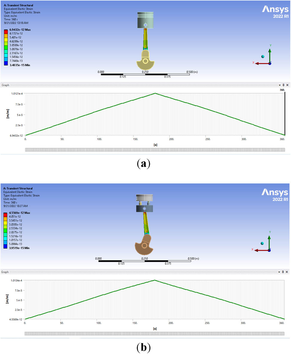
Figures 6–8 show the total deformation, equivalent elastic strain, and von-Mises stress that appear on the two types of pistons. In this regard, Figure 6(a) depicts the maximum total deformation of 8.57 × 10⁻² m on the conventional piston compared to Figure 6(b) 8.51 × 10⁻² m on the proposed piston. Statistically, the proposed piston has the capacity to mitigate the total deformation by 0.7%, as clarified in Figure 6(c). On the other hand, the equivalent elastic strain reached the highest value of 1.78 × 10⁻⁵ m/m in the conventional piston, while it was 6.2 × 10⁻⁵ m/m in the proposed piston, as shown in Figure 7. Furthermore, the von-Mises stress recorded was 3.518 × 10⁶ Pa in the conventional piston, and 1.218 × 10⁷ Pa in the proposed piston, which represents a significant increase of 71.1% in the proposed piston, as represented in Figure 8.
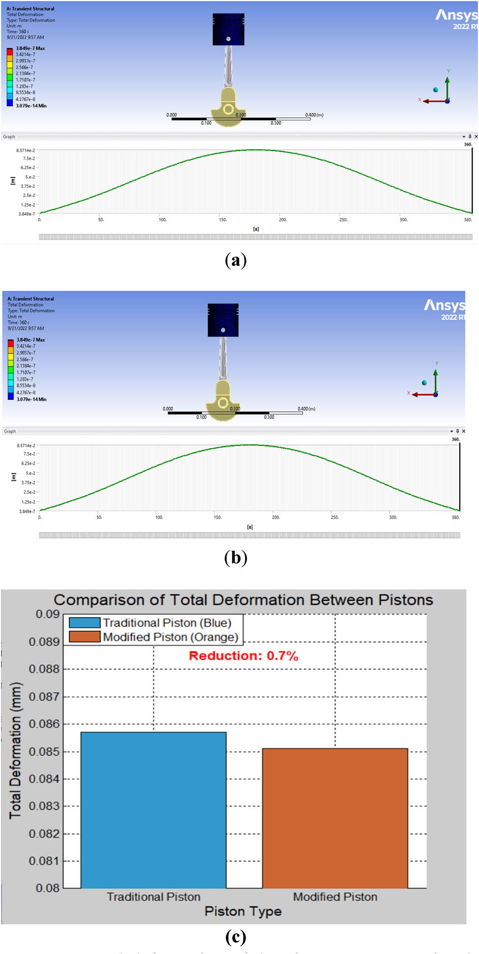
Total deformation of the piston: (a) conventional piston, (b) proposed piston, and (c) comparison of total deformation between conventional and proposed pistons.

Equivalent elastic strain: (a) conventional piston and (b) proposed piston.

Equivalent stress: (a) conventional piston and (b) proposed piston.
The inclusion of four shock absorbers in the modified design led to a decrease in deformation and stress for the modified piston when compared to the normal piston. Also, it is significant to show that because of their flexibility, these absorbers can reduce vibrations and lessen the stress and deformation on the piston’s two halves. This guarantees smooth motion transfer to the piston rod, second part, shock absorbers, and top part in that order. In addition, the findings demonstrate that the presence of flexible springs causes an increase in equivalent elastic strain. The maximum strain of the proposed piston is 6.2 × 10⁻⁵ m/m, which remains well within the allowable limit based on the yield strength of 1,300 MPa. The material operates within the elastic range of 4.04 × 10⁻³ m/m, making it safe in terms of elastic strain.
3.2 Total deformation, strain, and stress of the connecting rod
Figures 9–11 show the total deformation, equivalent elastic strain, and von-Mises stress that appear on the rod of the two types of pistons. Figure 9(a) presents the maximum total deformation of 4.766 × 10⁻³ m on the rod of the conventional piston, while Figure 9(b) shows 4.689 × 10⁻³ m on the rod of the proposed piston. Statistically, the proposed piston has the capacity to mitigate the total deformation by 0.016% and reduce the impact of deformation on the connecting rod. On the other hand, the equivalent elastic strain reached the highest value of 1.012 × 10⁻⁴ m/m in the connecting rods of the conventional piston, while the deformation on the connecting rods of the proposed piston was 1.013 × 10⁻⁴ m/m, as shown in Figure 10. Furthermore, the von-Mises stress was recorded to be 2.0154 × 10⁷ Pa on the rod of the conventional piston, as shown in Figure 11(a), and 2.02 × 10⁷ Pa on the rod of the proposed piston, as shown in Figure 11(b).

Total deformation of the connecting rod for (a) conventional piston and (b) proposed piston.
Elastic strain of the connecting rod for (a) conventional piston and (b) proposed piston.

Equivalent stress of the connecting rod for (a) conventional piston and (b) proposed piston.
Comparing the modified piston with the rod to the conventional piston, very little difference was found in the total deformation, strain, and stress of the connecting rod. This demonstrates that using the modified piston has no detrimental effects on the mechanical system or the connecting rod.
3.3 Analysis of linear acceleration and displacement
Figures 12–17 illustrate the acceleration, displacement, and frequency results obtained using SolidWorks 2022. This software was chosen for its ability to extract and visualize these parameters accurately. The engine system speed was set to 1,000 rpm, as SolidWorks allows for precise speed adjustments to simulate real engine conditions. The test duration was set to 5 seconds, as shown in the figures, to capture the dynamic behavior over multiple cycles. The piston, connecting rod, and crankpin were specifically selected for analysis due to their critical role in converting the piston’s reciprocating motion into rotational motion through the connecting rod and crankshaft mechanism.

Linear acceleration of the two piston designs at 1,000 rpm.

Linear displacement of the two piston designs at 1,000 rpm.

Linear acceleration of the connecting rod at 1,000 rpm.

Linear acceleration of the crank shaft pin at 1,000 rpm.

Frequency amplitude of conventional piston.

Frequency amplitude of proposed piston.
The analysis of linear acceleration and linear displacement of conventional and proposed pistons was evaluated. Figure 12 depicts that the maximum linear acceleration is 301,907 mm/s2 in the proposed piston compared to 301,955 mm/s2 in the conventional piston. Clearly, this introduces a reduction in the linear acceleration by 48 mm/s2 as a result of utilizing the proposed piston. However, the linear displacement has increased from 141.8 to 145.4 mm using the proposed piston, as presented in Figure 13.
The findings demonstrated that the modified piston had higher linear acceleration and displacement compared to the conventional piston. This difference is caused by the variation in spring length during compression while the crankshaft rotates.
Figures 14 and 15 show the linear acceleration on the connecting rod and crankshaft pin at an engine speed of 1,000 rpm. Indeed, Figure 14 shows a maximum linear acceleration of 282,545 mm/s2 on the rod of the proposed piston, while it recorded 265,610 mm/s2 on the rod of the conventional piston. This is an increase in the linear acceleration of the rod of around 6% due to using the proposed piston. However, the maximum linear acceleration of the crankshaft pin was recorded at 1,103 mm/s2 with the proposed piston compared to the conventional piston, which entails a remarkable increase of 241,664 mm/s2. Indeed, the proposed piston, therefore, has the capacity to decrease the maximum linear acceleration of the crankshaft by 99.5%. The results demonstrated that the modified piston increased crankshaft displacement and linear acceleration compared to the regular piston. This variation results from the modified piston’s shock absorbers moving as the crankshaft rotates.
3.4 Frequency results of the conventional and proposed pistons
Figures 16 and 17 show the vibration produced by the two pistons by plotting the amplitude and piston angle against the frequency. Specifically, the amplitude of the proposed piston starts from 1.271 m at 115 Hz, reaches its maximum value of 18.439 × 10⁻⁷ m at 1,150 Hz, and then drops to zero at 180 Hz. Similarly, the amplitude of the conventional piston starts at 8.63 × 10⁻¹¹ m at 581 Hz and reaches its maximum value of 238 × 10−6 m at 5,810 Hz.
4 Discussion
This research aimed to tackle the issue of piston-induced vibrations and stress in single-cylinder engines by developing a modified piston equipped with shock absorbers. The proposed design was compared with a conventional piston using detailed analysis of factors such as total deformation, equivalent elastic strain, and von-Mises stress. The findings show notable variations in the mechanical performance between the two designs under operational conditions. Specifically, the modified piston had a maximum total deformation of 8.51 × 10⁻² m, slightly less than the 8.57 × 10⁻² m recorded for the conventional piston, representing a 0.7% reduction. This suggests that the shock absorbers in the new design are effective at minimizing deformation by absorbing and redistributing mechanical loads. However, the equivalent elastic strain was higher in the modified piston (6.2 × 10⁻⁵ m/m) compared to the conventional design (1.78 × 10⁻⁵ m/m), indicating that the flexibility of the shock absorbers contributed to the increased strain 71.3% rise. Furthermore, the von-Mises stress in the new design was significantly higher, with values reaching 1.218 × 10⁷ Pa, as opposed to 3.518 × 10⁶ Pa in the conventional piston, reflecting a 71.1% rise. This increase could be linked to the load distribution across the shock absorbers, emphasizing the need for further refinement to optimize stress distribution.
Despite the increased stress and strain observed in the proposed piston, both values remain well within the yield strength of the high-strength steel used in the design, ensuring the material’s stability during operation. The highest stress levels were concentrated on the shock absorbers, which were specifically designed to reduce the load on the piston itself, thereby enhancing its durability. Fatigue tests conducted under cyclic loading confirmed that the design has the required fatigue life for the engine’s operational conditions. The strain levels also stayed within the material’s elastic limit, preventing any risk of permanent deformation. Additionally, the piston’s two-part design, which includes shock absorbers, effectively reduces the effects of vibration and stress fluctuations, contributing to the engine’s long-term reliability.
The current study utilized a specific type of steel for the pistons, springs, and connecting rods: heat-treated M42 Super HSS. Its chemical composition is as follows: carbon (1.08%), silicon (0.25%), manganese (0.25%), phosphorus (0.03%), sulfur (0.035%), chromium (3.75%), and molybdenum (9.5%). Moving toward the mechanical and thermal properties of the steel used for the piston and the springs of the shock absorbers, the researchers derived the following values from their analysis: Young’s modulus: 2 × 10¹¹ Pa, Poisson’s ratio: 0.3, bulk modulus: 1.7 × 10¹¹ Pa, shear modulus: 8 × 10¹⁰ Pa, compressive yield strength: 1,300 MPa, and thermal expansion coefficient: 10.4 × 10⁻⁶ 1/°C. Notably, this grade of steel was chosen for its ability to meet demanding conditions, including high strength, excellent toughness, and good fatigue resistance, which are essential for withstanding the dynamic and thermal stresses experienced by the piston. These properties contribute to the reduction of vibration and stress, making this material crucial for the proposed application.
When analyzing the performance of the connecting rod, only minor differences were noted between the two designs in terms of deformation, strain, and von-Mises stress. This indicates that the modified piston does not negatively impact the mechanical performance of the connecting rod, maintaining the overall system’s integrity. Linear acceleration and displacement tests at 1,000 rpm revealed that the modified piston slightly reduced maximum linear acceleration (301,907 mm/s2) compared to the conventional piston (301,955 mm/s2). However, the linear displacement increased from 141.8 to 145.4 mm with the new design. The higher linear acceleration observed in the modified piston, particularly on the connecting rod and crankpin, is likely due to increased inertia forces from the piston’s altered geometry and mass. These changes could affect engine balance, increasing vibrations and fatigue stresses on certain components. Nonetheless, the proposed piston halves function together seamlessly, as illustrated in Figure 3, preserving their overall functionality. Although the modified piston reduces acceleration slightly, it introduces greater displacement, likely as a result of the dynamic action of the shock absorbers during engine operation. Frequency analysis demonstrated that the modified piston exhibited lower vibration amplitudes across various frequencies, suggesting better vibration control, which is essential for improving the lifespan and reliability of single-cylinder engines, especially in scenarios where vibration-induced wear and user discomfort are critical concerns.
When comparing these results to previous studies, such as those by Sleesongsom and Bureerat [1] (focused on vibration suppression optimization) and Farrokhi Zanganeh et al. [3] (use of balancers), our approach presents an alternative solution by directly modifying the piston structure. Prior research by Jaber and Rai [4] and Zhang et al. [17] emphasized the value of advanced simulation tools such as ANSYS and CAD in piston optimization, further validating the methodology employed in this study.
In conclusion, the modified piston with integrated shock absorbers demonstrates promise in reducing deformation and vibrations while preserving the mechanical performance of the connecting rod. However, the observed increase in equivalent elastic strain and von-Mises stress highlights areas for further refinement. Future research should prioritize optimizing the shock absorber design to achieve better stress distribution and minimize strain. This could involve incorporating advanced materials and making geometric adjustments to enhance the overall performance. The study provides a deeper understanding of how optimized piston design and functionality can enhance engine reliability, efficiency, and thermal management while also reducing vibrations and wear. This targeted approach enables a more detailed exploration of specific challenges and advancements related to the piston system, offering valuable insights that can aid in the development of more robust single-cylinder engine designs.
5 Conclusions
This study established a new piston design using Solid Works software to reduce mechanical strains and vibration caused by early or erroneous engine ignition. Using ANSYS software, the total deformation, equivalent (von-Mises) stress, and equivalent elastic strain of the proposed and conventional pistons were measured and compared. As a result, the following major findings were made:
The proposed piston can reduce the maximum total deformation by 0.7%, while also reducing the mass of the piston by 30.8%.
Equivalent elastic strain and von-Mises stress were increased by 71.3 and 71.1%, respectively.
The maximum total deformation was decreased by 0.016% in the rod of the proposed piston.
The maximum linear acceleration was decreased on the connecting rod, crankshaft, and pistons in the engine when using the proposed piston. Future research should focus on material innovation, design optimization, and advanced thermal management, as well as dynamic analysis and wear testing to further enhance piston performance and durability. Additionally, evaluating fuel efficiency, emissions, and environmental impact will be crucial for sustainable implementation.
-
Funding information: The authors state no funding involved.
-
Author contributions: conceptualization, H.M.M., M.S.A. and Mo.H.; methodology, H.M.M. and Ma.H.; software, H.M.M. and L.J.H.; validation, O.K., N.F. and M.M.H.; formal analysis, Ma.H.; investigation, H.M.M. and L.J.H.; resources, O.K.; data curation, N.F.; writing – original draft preparation, H.M.M.; writing – review and editing, M.S.A., Mo.H. and M.M.H.; visualization, H.M.M.; supervision, M.S.A. and Mo.H.; project administration, M.S.A.; funding acquisition, Mo.H. All authors have read and agreed to the published version of the manuscript.
-
Conflict of interest: The authors state no conflict of interest.
-
Data availability statement: The data supporting the reported results are available from the corresponding author upon reasonable request.
References
[1] Sleesongsom S, Bureerat S. Vibration suppression of a single-cylinder engine by means of multi-objective evolutionary optimisation. Sustainability. 2018;10:2067.10.3390/su10062067Search in Google Scholar
[2] Gregório JP, Brójo FM. Development of a 4-stroke spark ignition opposed piston engine. Open Eng. 2018;8(1):337–43.10.1515/eng-2018-0039Search in Google Scholar
[3] Farrokhi Zanganeh N, Shahgholi G, Agh S. Studying the effect of balancer on engine vibration of Massey Ferguson 285 tractor. Acta Technol Agric. 2021;24:14–9.10.2478/ata-2021-0003Search in Google Scholar
[4] Jaber IJ, Ajeet KR. Design and analysis of IC engine piston and piston-ring using CATIA and ANSYS software. Int J Mech Eng Technol. 2014;5:64–73.Search in Google Scholar
[5] Koszalka G, Suchecki A. Analysis of design parameters of pistons and piston rings of a combustion engine. MATEC Web Conf. 2017;118:00013.10.1051/matecconf/201711800013Search in Google Scholar
[6] Ryabov AA, Romano VI, Rechkin VN, Kudryavtsev AY, Strelets DY. Computer technology of the thermal stress state and fatigue life analysis of turbine engine exhaust support frames. Open Eng. 2019;9(1):530–5.10.1515/eng-2019-0057Search in Google Scholar
[7] Liu B, Aggarwal SK, Zhang S, Tchakam HU, Luo H. Thermo-mechanical coupling strength analysis of a diesel engine piston based on finite element method. Int J Green Energy. 2024;21:732–44.10.1080/15435075.2023.2211139Search in Google Scholar
[8] Zhang S, Zhang Z. Research on the field dynamic balance technologies for large diesel engine crankshaft system. Shock Vib. 2017;2017:1–10.10.1155/2017/7150472Search in Google Scholar
[9] Zavos AB, Nikolakopoulos PG. Simulation of piston ring tribology with surface texturing for internal combustion engines. Lubr Sci. 2015;27:151–76.10.1002/ls.1261Search in Google Scholar
[10] Fan J, Zhang J, Yu H. Establishment of coupling simulation model of diesel engine combustion process and mechanical system dynamics. 2024;3499–509.10.1007/978-981-99-8048-2_243Search in Google Scholar
[11] Viswanath AS, Bharathraja S, Deepika R, Jegatheesh Ramnath J. Design and analysis of piston on different materials using CAE tools. Int J Eng Res Technol. 2021;9(10):37–43.Search in Google Scholar
[12] Kral J, Palko M, Palko M, Pavlikova L. Design and development of ultra-light front and rear axle of experimental vehicle. Open Eng. 2020;10(1):232–7.10.1515/eng-2020-0032Search in Google Scholar
[13] Zych P, Żywica G. Optimisation of stress distribution in a highly loaded radial-axial gas microturbine using FEM. Open Eng. 2020;10(1):318–35.10.1515/eng-2020-0036Search in Google Scholar
[14] Sri M, Vasu P, Rama Murthy D, Krishna SVG. Design and analysis of IC engine piston with different materials. Int J Res. 2018;5:871–8.Search in Google Scholar
[15] Aichlmayr HT, Kittelson DB, Zachariah MR. Miniature free-piston homogeneous charge compression ignition engine-compressor concept—Part I: Performance estimation and design considerations unique to small dimensions. Chem Eng Sci. 2002;57:4161–71.10.1016/S0009-2509(02)00256-7Search in Google Scholar
[16] Shetty AK, Abijeet TK, Machado JW, Shrivathsa TV. Design and analysis of piston using aluminium alloys. Int J Innov Res Adv Eng. 2017;4:1–6.Search in Google Scholar
[17] Zhang XM, Wang YQ, Fang J. Dynamic simulation of crank-connecting rod-piston mechanism of internal combustion engine based on virtual prototype technology. Appl Mech Mater. 2011;143–4:433–6.10.4028/www.scientific.net/AMM.143-144.433Search in Google Scholar
[18] Andoko, Saputro NE. Strength analysis of connecting rods with pistons using finite element method. MATEC Web Conf. 2018;204:07009.10.1051/matecconf/201820407009Search in Google Scholar
[19] Patnaik L, Saravanan I, Kumar S. Die casting parameters and simulations for crankcase of automobile using MAGMAsoft. Mater Today Proc. 2020;22:563–71.10.1016/j.matpr.2019.08.208Search in Google Scholar
[20] Dhummansure V, Doddamani S, Jamadar NI, Mohamed Kaleemulla K. Structural and modal analysis of crankcase of single-cylinder diesel engine. Int J Interact Des Manuf. 2023;17:1215–23.10.1007/s12008-022-01101-xSearch in Google Scholar
[21] Fonte M, Duarte P, Reis L, Freitas M, Infante V. Failure mode analysis of two crankshafts of a single-cylinder diesel engine. Eng Fail Anal. 2015;56:185–93.10.1016/j.engfailanal.2015.02.014Search in Google Scholar
[22] Kurczyński D, Łagowski P, Warianek M. Research on the combustion process in the Fiat 1.3 Multijet engine fueled with rapeseed methyl esters. Open Eng. 2021;11(1):535–47.10.1515/eng-2021-0057Search in Google Scholar
[23] Leuva HK, Shah SA, Bhargav HA. Computational analysis of reciprocating compressor piston for lifetime performance. Int Conf Res Innov Sci Eng Technol. 2017;1:354–64.10.29007/rfwzSearch in Google Scholar
[24] Summer F, Grün F, Schiffer J, Gódor I, Papadimitriou I. Tribological study of crankshaft bearing systems: Comparison of forged steel and cast iron counterparts under start–stop operation. Wear. 2015;338–9:232–41.10.1016/j.wear.2015.06.022Search in Google Scholar
[25] Zhang X, Zheng L. Investigation on the dynamics of a flexible multi-body system of a three-cylinder gasoline engine crankshaft. Processes. 2023;11:1248.10.3390/pr11041248Search in Google Scholar
[26] Guo R, Zhou Z. Influence of mass unbalancing of three-cylinder engine on idle vibration based on powertrain model. Vibroeng Procedia. 2019;28:81–6.10.21595/vp.2019.21037Search in Google Scholar
[27] Gupta AK, Venkatakiran B, Rahul K, Panwar A, Joshi M. Digital approach for dynamic balancing of three-cylinder gasoline engine crank-train. Symposium on International Automotive Technology, 2021-26-0265; 2021.10.4271/2021-26-0265Search in Google Scholar
[28] Wannas AA, Hadi AS, Hamza NH. Elastic–plastic analysis of the plane strain under combined thermal and pressure loads with a new technique in the finite element method. Open Eng. 2022;12(1):477–84.10.1515/eng-2022-0049Search in Google Scholar
[29] Bogdan D, Derbiszewski M, Wozniak J, Zakrzewski S, Kaczmarek M, Binkowski D, et al. Research of dynamic phenomena in a model engine stand. Open Eng. 2023;13(1):20220436.10.1515/eng-2022-0436Search in Google Scholar
© 2025 the author(s), published by De Gruyter
This work is licensed under the Creative Commons Attribution 4.0 International License.
Articles in the same Issue
- Research Article
- Modification of polymers to synthesize thermo-salt-resistant stabilizers of drilling fluids
- Study of the electronic stopping power of proton in different materials according to the Bohr and Bethe theories
- AI-driven UAV system for autonomous vehicle tracking and license plate recognition
- Enhancement of the output power of a small horizontal axis wind turbine based on the optimization approach
- Design of a vertically stacked double Luneburg lens-based beam-scanning antenna at 60 GHz
- Synergistic effect of nano-silica, steel slag, and waste glass on the microstructure, electrical resistivity, and strength of ultra-high-performance concrete
- Expert evaluation of attachments (caps) for orthopaedic equipment dedicated to pedestrian road users
- Performance and rheological characteristics of hot mix asphalt modified with melamine nanopowder polymer
- Second-order design of GNSS networks with different constraints using particle swarm optimization and genetic algorithms
- Impact of including a slab effect into a 2D RC frame on the seismic fragility assessment: A comparative study
- Analytical and numerical analysis of heat transfer from radial extended surface
- Comprehensive investigation of corrosion resistance of magnesium–titanium, aluminum, and aluminum–vanadium alloys in dilute electrolytes under zero-applied potential conditions
- Performance analysis of a novel design of an engine piston for a single cylinder
- Modeling performance of different sustainable self-compacting concrete pavement types utilizing various sample geometries
- The behavior of minors and road safety – case study of Poland
- The role of universities in efforts to increase the added value of recycled bucket tooth products through product design methods
- Adopting activated carbons on the PET depolymerization for purifying r-TPA
- Urban transportation challenges: Analysis and the mitigation strategies for road accidents, noise pollution and environmental impacts
- Enhancing the wear resistance and coefficient of friction of composite marine journal bearings utilizing nano-WC particles
- Sustainable bio-nanocomposite from lignocellulose nanofibers and HDPE for knee biomechanics: A tribological and mechanical properties study
- Effects of staggered transverse zigzag baffles and Al2O3–Cu hybrid nanofluid flow in a channel on thermofluid flow characteristics
- Mathematical modelling of Darcy–Forchheimer MHD Williamson nanofluid flow above a stretching/shrinking surface with slip conditions
- Energy efficiency and length modification of stilling basins with variable Baffle and chute block designs: A case study of the Fewa hydroelectric project
- Renewable-integrated power conversion architecture for urban heavy rail systems using bidirectional VSC and MPPT-controlled PV arrays as an auxiliary power source
- Exploitation of landfill gas vs refuse-derived fuel with landfill gas for electrical power generation in Basrah City/South of Iraq
- Review Articles
- A modified adhesion evaluation method between asphalt and aggregate based on a pull off test and image processing
- Architectural practice process and artificial intelligence – an evolving practice
- Special Issue: 51st KKBN - Part II
- The influence of storing mineral wool on its thermal conductivity in an open space
- Use of nondestructive test methods to determine the thickness and compressive strength of unilaterally accessible concrete components of building
- Use of modeling, BIM technology, and virtual reality in nondestructive testing and inventory, using the example of the Trzonolinowiec
- Tunable terahertz metasurface based on a modified Jerusalem cross for thin dielectric film evaluation
- Integration of SEM and acoustic emission methods in non-destructive evaluation of fiber–cement boards exposed to high temperatures
- Non-destructive method of characterizing nitrided layers in the 42CrMo4 steel using the amplitude-frequency technique of eddy currents
- Evaluation of braze welded joints using the ultrasonic method
- Analysis of the potential use of the passive magnetic method for detecting defects in welded joints made of X2CrNiMo17-12-2 steel
- Analysis of the possibility of applying a residual magnetic field for lack of fusion detection in welded joints of S235JR steel
- Eddy current methodology in the non-direct measurement of martensite during plastic deformation of SS316L
- Methodology for diagnosing hydraulic oil in production machines with the additional use of microfiltration
- Special Issue: IETAS 2024 - Part II
- Enhancing communication with elderly and stroke patients based on sign-gesture translation via audio-visual avatars
- Optimizing wireless charging for electric vehicles via a novel coil design and artificial intelligence techniques
- Evaluation of moisture damage for warm mix asphalt (WMA) containing reclaimed asphalt pavement (RAP)
- Comparative CFD case study on forced convection: Analysis of constant vs variable air properties in channel flow
- Evaluating sustainable indicators for urban street network: Al-Najaf network as a case study
- Node failure in self-organized sensor networks
- Comprehensive assessment of side friction impacts on urban traffic flow: A case study of Hilla City, Iraq
- Design a system to transfer alternating electric current using six channels of laser as an embedding and transmitting source
- Security and surveillance application in 3D modeling of a smart city: Kirkuk city as a case study
- Modified biochar derived from sewage sludge for purification of lead-contaminated water
- The future of space colonisation: Architectural considerations
- Special Issue: AESMT-7 - Part II
- Experimental study on behavior of hybrid columns by using SIFCON under eccentric load
- Special Issue: ICESTA-2024 and ICCEEAS-2024
- A selective recovery of zinc and manganese from the spent primary battery black mass as zinc hydroxide and manganese carbonate