The heuristic model of energy propagation in free space, based on the detection of a current induced in a conductor inside a continuously covered conducting enclosure by an external radio frequency source
-
Chithra Kirthi Gamini Piyadasa
 ,
Udaya Annakkage
,
Udaya Annakkage

Abstract
The objective of this study is to propose a heuristic model of energy propagation due to an anomaly; electromagnetic (EM) field penetration into a continuously covered conducting enclosure (Faraday shield) from an external radio frequency source, violating the accepted model in the EM field theory. In this study, at an arbitrarily selected frequency, range of 26.965–1,800 MHz, of an external frequency source, an EM field inside the conducting enclosure was observed, contrary to expectations, which was followed by a systematic examination. Although no induced voltage could be expected inside the enclosure according to the classical theory, the experiment revealed a clear induced voltage inside, an attenuated induced voltage of −18.0 to −1.0 dB (for the range of frequencies 26.965–1,800 MHz) was observed. Hence, these results apparently contradict the established notion that an EM field cannot penetrate a Faraday shield. Rationalizing these observations and the results of the investigation leads to an alternative model to the existing models of energy propagation in free space. In this model, novel quantities named “I-Spin-energy” and “I-Spin-energy field” are defined to replace the concept of electric and magnetic fields in the classical EM theory. The proposed I-Spin-energy model is capable of explaining the unexpected presence of the EM field inside the Faraday shield as well as the induction of an alternating current in a conductor placed inside a Faraday shield along with other existing observations in physics such as those in famous Young’s double-slit experiment on interference of light, which provided the basis for the wave theory.
1 Introduction
As any new revelation has a bearing on the accepted existing knowledge, some analysis of the electromagnetic (EM) field becomes expedient. The experiments shown here discuss most fundamental concepts related to the classical EM field, and these fundamental concepts are recalled in this section with fine detail to show their contradictory nature with the observations obtained in these experiments. Energy propagation in free space has been described by the wave theory and the quantum theory. Most naturally occurring phenomena have been modelled by using either of these theories [1,2]. In radio frequency shielding, energy is considered to propagate in the form of EM waves, which consist of self-propagating transverse oscillating coupled waves of electric and magnetic fields perpendicular to each other and perpendicular to the direction of the propagation of energy. The solutions for linearly polarized planar electric and magnetic fields, E (r) and B (r), respectively, at any given point r relative to any arbitrary point in free space are expressed as follows:
where k is the wave vector normal to the plane of the EM wave, r(x, y, z) is the position vector, E 0 is the amplitude of the electric field, and B 0 is the amplitude of the magnetic field. The behavior of the propagating EM waves is mathematically expressed by Maxwell’s equations [3,4]. Maxwell’s equations describe the electric and magnetic fields arising from the distribution of charges and currents. Maxwell’s first equation (Gauss’ law) states that the electric flux out of any closed surface is proportional to the total charge enclosed by the surface. The following equation expresses its integral form when a charge q is enclosed by a closed surface A, resulting in an electric field E :
where ε is the permittivity of the medium.
There was no charge inside the conducting enclosure, as all the charges exist on the conducting outer surface [4]. Therefore, following Gauss’ law and symmetry, the electric field inside the conducting enclosure is zero. In fact, according to equation (2), the electric field inside any closed hollow conductor is zero, provided that the region enclosed by the conductor contains no free charge.
As a result, when a time-varying EM wave encounters such a hollow conducting enclosure, according to the classical EM theory, two simultaneous mechanisms occur independent of the frequency or wavelength of the incident EM wave.
As shown in Figure 1(a), the transmitted electric field component of the EM wave travels through the wall of the conducting enclosure and redistributes free charges inside the conducting enclosure by induction. Once an opposing electric field is created by the induced charges on the surface of the conducting enclosure, the resultant electric field inside the enclosure becomes zero [5].
As shown in Figure 1(b), the incident magnetic field component of the EM wave induces eddy currents [5] (blue arrow) due to free charges in the conducting body. The eddy currents generate an opposing magnetic field (red arrow), canceling the incident magnetic field at the enclosure. The resultant magnetic field inside the enclosure is zero. Therefore, no magnetic field appears inside the hollow conducting enclosure [6].
According to the aforementioned theory, now established, no electric field or time-varying magnetic field can exist inside a hollow conducting enclosure, and no electric field from outside can penetrate the enclosure (Figure 1). Such an enclosure is called an EM shield or a Faraday shield [7].

When an EM wave encounters a hollow conducting enclosure, according to the classical theory of electromagnetism, two simultaneous mechanisms occur. (a) The transmitted electric field component (black dashed arrows) of the EM wave travels through the wall of the conducting enclosure and redistributes free charges in the conducting wall because of induction. An opposing electric field (blue dashed arrows) is created by the induced charges on the surface of the conducting enclosure, resulting in zero electric field inside the conducting wall. (b) The incident magnetic field component (black arrows) induces eddy currents (blue arrow) in the wall of the conducting enclosure. The eddy currents generate an opposing magnetic field (red arrow), canceling the incident magnetic field at the enclosure. Therefore, no magnetic field appears inside the closed conducting enclosure.
Summarizing, in a Faraday shield, the EM wave separately (not bounded together) exerts two individual forces (due to electric and magnetic fields) on the surface of the enclosure and produces a net zero EM field in the interior of the conducting enclosure (Figure 1).
The Faraday shield concept is widely applied in present-day industries for shielding instruments and processes from EM interference [8,9], such as medical instruments, analytical instruments, and electronic and communication systems. However, it is important to note that all the instruments and implements used inside the Faraday shield are strictly grounded to the Faraday shield itself to provide proper shielding. This is the most important criterion in the present-day use of a Faraday shield [6]. However, according to the working principle of the Faraday shield, there should be no need for the instruments used inside the shield to be connected to the Faraday shield and grounded, as there is no EM field that can penetrate the shield from external sources [5]. Moreover, there is evidence showing that, even when the grounding technique is utilized, the EM field still continues to exist inside the Faraday shield [10,11,12].
If a field due to an external EM source penetrates/exists inside a Faraday shield, the present theory suggests that either the enclosure is not perfectly closed because of apertures (e.g., holes in the enclosure) or the enclosure is completely closed, but the wall is too thin to provide adequate shielding.
In the case of an imperfect enclosure, the penetration depends on the size of the openings. The case in which the conducting enclosure has openings facing the emission of radiation has been extensively and rigorously studied elsewhere [13,14,15,16]. According to the EM field theory, EM waves do not penetrate very far through holes that are significantly less than a wavelength across [13,17]. Equivalently, the reflection of EM waves from a conducting surface is not affected by the holes (or other irregularities) on the surface, which are significantly less than a wavelength across. Therefore, a Faraday shield (in this case, it is commonly known as a Faraday cage even when such holes are present on the surface) or an antenna reflector is constructed by using a metallic wire mesh (with a spacing that is small compared with the wavelength) without a drastic compromise in performance. It is important to note that the commonly referred Faraday cage is not essentially a continuous covering, as it may contain openings. In this study, only continuously covered conducting enclosures (i.e., without openings) are considered and referred to as Faraday shields.
As discussed above, when holes exist on an imperfect metal surface, the penetration of EM waves through these holes depends on the incident frequency. The incident frequency is categorized into high-, intermediate-, and low-frequency regions relative to the dimensions of the holes on the surface [18]. If a hole is large compared with the incident wavelength, it is considered a high-frequency region, and EM waves pass freely through the hole (i.e., aperture). Many of the laws of physical optics are applied under this assumption. Resonance occurs (aperture excitation) [19] when the aperture dimensions are approximately equal to the wavelength, and the respective frequencies are considered as being in the intermediate-frequency region. In the low-frequency region, where the aperture is small compared with the wavelength, the laws of Kirchhoff–Fresnel [20,21,22,23,24] diffraction or boundary diffraction wave [25,26,27,28] can be applied to analyze the field distribution.
In case of a thin wall, the EM field can be transmitted through and can appear inside the Faraday shield (Figure 2) [18,29,30,31,32]. When an EM wave with an energy I dB is incident on a metal wall of thickness t, the EM energy is partially reflected (R dB) and partially absorbed (A dB) by the metal wall. Some of the EM energy (T dB) penetrates the metal wall depending on the thickness t, permeability µ, permittivity ε, and conductivity σ of the wall. The energy conservation when an EM wave is incident on a conducting wall is expressed by equation (3), and the shielding effectiveness (SE) is defined by equation (4):
SE can be determined when the reflection losses (R dB) defined by equation (5) and absorption losses (A dB) defined by equation (6) are known [31] for a given I dB:

EM shielding. When an EM wave is incident on a metal wall of thickness t, the EM energy is partially reflected and partially absorbed by the metal wall. Some of the EM energy penetrates the metal wall depending on the thickness t, permeability µ, permittivity ε, and conductivity σ of the wall. The electric and magnetic field components of the incident, reflected, and transmitted waves are ( E i, H i), ( E r, H r), and ( E t, H t), respectively.
The SE through a conducting wall is considered as two separate components, as in the case of a Faraday shield (Figure 1): the electric field shielding effectiveness (SEE) and magnetic field shielding effectiveness (SEM). The SE of electric and magnetic fields is defined as the ratio of the field magnitude at a point without and with the metal wall [31]:
where E i and E t are the electric fields of the incident and transmitted waves, respectively, and H i and H t are the incident and transmitted magnetic fields, respectively.
The value of E i/ E t can be calculated as follows:
where η is the radiation impedance of the medium. For a conducting enclosure, the atmospheric conditions are roughly equivalent to those of free space. Therefore,
The impedance of the conductor,
Since
With a higher electrical conductivity, when the frequency of the incident wave increases, most of the EM energy is concentrated near the surface of the metallic enclosure because of the eddy currents. This also causes negligible EM fields inside the enclosure (Figure 1). This is known as the skin effect [33,34], and the skin depth δ describes the depth to which radiation can penetrate the shield. The skin depth is expressed as follows:
where f is the frequency of the incident EM wave, μ 0 is the absolute magnetic permeability, ρ and μ r are the conductivity and the relative permeability of the conducting material, respectively.
In addition to the electrical conductivity (σ) and permeability (μ) of the conducting material, the dielectric absorption and surface porosity of the enclosure affect the penetration and reflection of EM waves [35].
The electric field in a Faraday shield, irrespective of the shape of it [5], due to an externally applied electrostatic field has been explained in the same manner to that due to a time-varying electric field. In the case of an external static magnetic field, the shielding depends on the permeability of the material and the shape of the conducting enclosure [4].
Furthermore, the understanding is that the induction takes place instantly in the metal when the external electrostatic field is applied. Induction in a time-varying electric field such as an EM field depends on the permittivity (ε – dielectric constant) of the substance. The dielectric constant of a metal is not relevant here, as metals cannot store energy in the presence of an electric field. The relative permittivity of good conductors such as copper, silver, and gold is considered as 1 (one) for calculations.
In electromagnetism, the electric displacement field ( D ) represents how an electric field ( E ) influences the organization of electric charges in a given medium, including charge migration and electric dipole reorientation. Its relation to permittivity in the very simple case of linear, homogeneous, isotropic materials with “instantaneous” response to changes in electric field is given by:
Here, it shows that the induction takes place instantly in the metal when the external time-varying electric field is applied, similar to the electrostatic case.
However, the formation of a zero EM field within a Faraday shield due to the individual actions of the electric and magnetic fields has not been adequately studied empirically, relevant to the classical EM wave theory.
Only a limited number of computational studies [36,37] based on the existing models have been carried out so far to investigate the EM field shielding of spherically shaped shells with or without apertures, which does not reflect the actual practical situation.
To address this shortcoming, the following experiments were designed to investigate the shielding process within a Faraday shield at randomly chosen frequencies (26.965, 151.880, 500, 900, and 1,800 MHz). The voltage signals due to induced currents in a simple monopole conductor were examined with and without a Faraday shield (constructed with a 1.2-mm-thick copper sheet).
The above experiment has clearly indicated the presence of electric and magnetic fields inside the Faraday shield (details are discussed later in this article), contradicting the existing understanding of this phenomenon, which predicts a zero EM field inside the Faraday shield by the reasoning that free electrons in the metal redistribute themselves dynamically to create a counteracting EM field that cancels the internal field. According to the classical theory, the zero EM field inside a Faraday shield is described by the fundamental aspects of electric and magnetic fields, and the zero field completely depends on the free charges (electrons) of the metal. This fact leads to a contradiction if those free charges are bounded and immobilized by another strong external electric field. In this situation, free charges would not be available for creating a zero EM field, and an external EM field should appear inside the Faraday shield. This aspect is out of the scope of this study and to be discussed separately.
The authors being concerned that having incorporated a standard Faraday shield complying to established properties (specifications) showing up an observation contrary to the established theory, viz., not only the detection of an EM wave inside the cage, but also the induction of a detectable current inside it. Hence, the contention that an alternative hypothesis is needed to explain the observations.
Explaining further, the E-field detected inside the faraday shield cannot be explained by the existing theory. Subsequent observations made using appropriate experimental setups (detailed in Section 2) also led to the new model of energy propagation in free space.
Experiments showing the presence of energy fields that can induce a current in a conductor placed inside the Faraday shield are presented in Part-A of this article. Thus, these experiments have convincingly revealed an energy field inside the Faraday shield. Furthermore, the observation that an induced current can arise in a conductor inside a Faraday shield confirms the above fact. Thus, an E-field can penetrate a Faraday shield from outside to inside. Hence, an alternative theory for the propagation of energy is required.
In Part-B, to explain our observations, an alternative heuristic model has been proposed for the propagation of energy in free space. In this model, new quantities named “I-Spin-energy” (Intrinsic Spin Energy or ISpE) and “I-Spin-energy field” (Intrinsic Spin Energy Field or ISpEF) are defined to replace the role of electric and magnetic fields in the classical EM wave theory.
2 Part-A
2.1 Method
2.1.1 Primary study of field penetration
To detect if a signal is present within the Faraday shield, an antenna and a receiver were placed inside a Faraday shield, as shown in Figure 3. Two similar copper cubic enclosures (CuCuE) of dimensions 55 cm × 55 cm × 55 cm were carefully built based on the standard shielding methods [38], preventing EM field leakage. Copper sheets of 1.2 mm thickness were used for the construction. One chamber was built by soldering using Sn/Pb (63:37) to reduce cold solder joints, and the other was built with copper tungsten inert gas (TIG) welding. Both chambers showed similar results throughout the experiment. Therefore, no discussion is made on the construction technique, which is irrelevant.

Experimental setup I: a copper box of dimensions 55 cm × 55 cm × 55 cm (1.2 mm thickness) was irradiated with radio frequencies of 26.965, 151.880, 500, 900, and 1,800 MHz. A device for measuring signal strength was placed inside the chamber.
The CuCuE shield was irradiated with external EM sources (external radio frequency transmitter) at frequencies of 26.965 (1,111 cm), 151.880 (200 cm), 500 (60 cm), 900 (33 cm), and 1,800 (16.7 cm) MHz. For 26.965, 151.880, and 500 MHz, a tuned RF power meter was used to measure the field inside. For 900 and 1,800 MHz, the commercial GSM900 and GSM1800 signals were used, respectively. GSM mobile phones installed with applications for signal strength measurements were used as receivers. The voltage signals due to induced currents in a simple monopole conductor were measured with and without a Faraday shield in place. Thirty signal strength measurements have been taken for each frequency value for statistical significance. The results are discussed in Section 3. As a significantly strong signal was detected, contrary to the classical EM theory interpretation within the CuCuE at all frequencies, a further detailed experiment was designed to investigate the field detected within the Faraday shield.
2.1.2 Detailed study of field penetration
In this experiment, only a single source of frequency 151.880 MHz was selected arbitrarily.
Experiment apparatus
Two monopole antennae (410 mm long).
One square-loop antenna (410 mm × 40 mm).
As shown in Figure 4, a closed Faraday shield was made using a 1.2-mm-thick copper sheet with a circular base of 50 mm diameter and approximately 420 mm height. To measure the voltage signals due to the induced current in the antenna inside, two holes of 10 mm diameter were made on the circular base for the Bayonet Neill–Concelman (BNC) connectors. This design of the Faraday shield is named as a copper cylindrical enclosure (CuCyE).
Two separate battery-operated digital oscilloscopes (Tektronics TPS 2024) having four isolated channels were used for the voltage measurements. In an isolated channel oscilloscope, each channel has its own ground, and these ground terminals were not connected to each other.
2 W/151.880 MHz vertically polarized sinusoidal signal source.
Equal-length 50 Ω coaxial cables.
The dimensions of antennae and CuCyE were selected to be close to the quarter wavelength of the source frequency of 151.880 MHz. Two separate digital oscilloscopes were used to minimize the coupling between the antenna measurements. The transmitting antenna was a 0.5 m quarter wavelength vertical telescopic monopole antenna. The experiment was performed under general indoor propagation conditions. The transmitter was placed 8 m away from the Faraday shield.
Both oscilloscopes have to be triggered at the same instant in order to record the input signals at the oscilloscopes precisely. This was achieved by connecting two separate antennae at the trigger inputs of each oscilloscope as shown in Supplementary Figure 1 (see Supplementary data Note 1). Now the signals induced in the antennae in trigger inputs, by the signal source (ERFT), initiate recording at the same moment. Both antennae were placed approximately the same distance away from the 151.880 MHz source. Observations made with two oscilloscopes were similar to those made with two separate isolated channels, CH1 (with its groundCH1) and CH2 (with its groundCH2), of a single oscilloscope. Therefore, two separate isolated channels of a single oscilloscope were used when the magnitudes and phases were measured simultaneously for two signals. In the experiments, the induced currents at the antennae were measured as voltage across the input impedance (1 MΩ) of the oscilloscope.
The near-field distance from the transmitting antenna is approximately equal to 2L 2/λ [39], where L is the highest length of the antenna. This yields a near-field distance of 1.5 m. Therefore, as the distance between the source and the antenna was 8 m, the near-field behaviors of the EM waves are excluded in this study.
The following three experiments were performed.
Exp. II(a). Two monopole antennae, Ant-1 and Ant-2, were placed inside the CuCyE and connected to oscilloscopes CH2 and CH1, respectively, via BNC connectors. The screen of the coaxial wire to Ant-1 was connected to the oscilloscope groundCH2 but it was not connected to the CuCyE (an isolated connector, AMP 112431, was used for BNC 1). The screen of the coaxial wire of Ant-2 was connected to the oscilloscope groundCH1 as well as to the CuCyE via BNC 2 (AMP 227755-1). As shown in Figure 4(a), the cable end connected to BNC 1 was additionally screened by a copper foil to restrict possible EM penetration in the CuCyE through the gap. The gap between the CuCyE and the outer coaxial screen of the insulated BNC 1 was approximately 0.2 mm. Two voltage measurements from Ant-1 and Ant-2 were taken without the shield, CuCyE (only the base, after removing the CuCyE; see Supplementary data, Note 2 (Supplementary Figure 2), and with the shield (antennae enclosed with the CuCyE, as shown in Figure 4(a)). The 151.880 MHz signal source was used to create a field at the CuCyE. Exp. II(a) was repeated with six isolated enclosures (enclosures within enclosures) but only with Ant-1: the details and results are provided in the Supplementary data (Supplementary data, Note 3 and Supplementary Figure 3). Ant-1 and Ant-2 were also shielded with multiple configurations: the details of which and the results are provided in the Supplementary data (Notes 4 and 5) and Supplementary Figures 4 and 5.

Experimental setup II: (a) two monopole antennae, Ant-1 and Ant-2, were connected to a digital oscilloscope using two equal-length coaxial cables. The outer shield/screen (oscilloscope ground) of the coaxial cable from CH2 was not connected to the CuCyE at BNC-1 (isolated connector – AMP 112431). However, an additional shield was made at the BNC-1 to restrict possible field penetration into the CuCyE. The screen of the coaxial wire of Ant-2 was connected to the oscilloscope groundCH1 and to the CuCyE via BNC 2 (AMP 227755-1). (b) To determine whether a time-varying magnetic field exists inside the copper enclosure, a rectangular wire loop antenna shunted by a 50 Ω resistor was placed inside the enclosure. (c) Ant-1 and the CuCyE were separately connected to the oscilloscope using coaxial cables. In Exp. II(c), the outer shields (oscilloscope grounds) of both coaxial cables were not connected to the CuCyE. Connections to the antennae and the CuCyE were made through an insulated BNC.
Exp. II(b). This experiment was performed to determine whether a time-varying magnetic field existed inside the CuCyE. The two antennae were replaced by a rectangular wire loop antenna shunted with a 50 Ω resistor, as shown in Figure 4(b). Oscilloscope CH1 and its groundCH1 terminals were directly connected to the two ends of the wire loop, as shown in Figure 4(b). As in Exp. II(a), the unshielded and shielded voltage measurements were taken when the 151.880 MHz signal source creates a field at the CuCyE.
Exp. II(c). The third experimental setup is shown in Figure 4(c) and uses a single enclosed antenna. Ant-1 was connected to oscilloscope CH2 as in Exp. II(a). The housing of the CuCyE was independently connected to oscilloscope CH1 using coaxial cable as shown in Figure 4(c). Note that the outer shields (oscilloscope grounds) of both coaxial cables were not connected to the CuCyE. Again, the 151.880 MHz external signal source was used to create a field at the CuCyE.
For each experiment, to observe the impact of noise, the signals induced in the cables connected to the CuCyE were measured without the antennae (Supplementary data, Note 6 and Supplementary Figure 6). The 151.880 MHz external signal source was in operation when the measurements were taken. In addition, the experiments were repeated with the CuCyE grounded to the actual ground and electrical ground of the main power supply.
Finally, the experimental setups were simulated using Ansys High Frequency Structure Simulator (HFSS) 13.0.0, and the results of the experiments and respective simulations were compared.
3 Results
3.1 Primary study of field penetration
Table 1 summarizes the results of the primary study of field penetration. For frequencies of 26.965, 151.880, 500, 900, and 1,800 MHz, the power induced in the monopole conductor without and with the CuCuE (Figure 3) is given in Table 1, where the signal strength is given in dBm.
Signal strength measured in dBm without and with the copper enclosure for frequencies of 26.965, 151.880, 500, 900, and 1,800 MHz. Mean value of 30 signal strength measurements have been taken for each frequency value. The standard deviation for each signal strength measurement was calculated and included in parenthesis next to the dBm value
| Frequency (MHz) | Wavelength (cm) | Signal strength, dBm, (SDa) | Signal source Off (dBm) | S w/S wo (dB) | |
|---|---|---|---|---|---|
| Without CuCuE (S wo) | With CuCuE (S w) | ||||
| 26.965 | 1,110 | −10 (0.14) | −28 (0.20) | ∼−59 | −18.1 |
| 151.880 | 200 | −29 (0.20) | −36 (0.22) | ∼−59 | −7.0 |
| 500 | 60 | −23 (0.19) | −31 (0.19) | ∼−59 | −8.0 |
| 900 | 33.3 | −96 (0.85) | −97 (1.38) | n/a | −1.0 |
| 1,800 | 16.7 | −97 (1.13) | −98 (1.17) | n/a | −1.0 |
- a
SD – standard deviation.
For the selected frequencies within the 26.965–1,800 MHz band, the calculated ratio between the measured voltages (S W/S W0) due to the induced current at the antenna without the CuCuE (S W) to those with the CuCuE (S W0) is in the range of −18.1 to −1.0 dB. The S W/S W0 ratio of the voltages due to the induced currents (measured voltages with and without the Faraday shield) is useful as a quantitative index of the extent of the penetration of the signal. The data in Table 1 also indicate that the signal inside the conducting CuCuE increases with the decrease in wavelength relative to the dimensions of the CuCuE. At 1,800 MHz, the effect of the Faraday shield is very small in the observed frequency range. Most interestingly, the results confirmed that EM energy penetrates walls and exists within the CuCuE, contradictory to the classical interpretation of the Faraday shield.
3.2 Detailed study of field penetration
The observed voltage waveforms and the analysis in the detailed study of field penetration are given in the supplementary data (Note 7, Supplementary Figure 7(i) and (ii)).
Only measured voltages due to induced currents in Ant-1, Ant-2, and loop antennae (Exp. II(a) and Exp. II(b)) without and with the Faraday shield (i.e., CuCyE) are summarized in Table 2.
Induced voltages at Ant-1, Ant-2, and the loop antenna in Exp. II(a) and Exp. II(b)
| Antenna | Exp. II(a) voltage (mV) | Exp. II(b) voltage (mV) | ||
|---|---|---|---|---|
| without CuCyE | with CuCyE | without CuCyE | with CuCyE | |
| Ant-1 | 816 | 1,460 | — | — |
| Ant-2 | 808 | 32 | — | — |
| Loop | — | — | 288 | 488 |
The voltages measured due to currents induced in the Ant-1 and Faraday shield (CuCyE) and the description in Exp. II(c) is given in Note 7 and Figure 7(ii).
Exp. II(a) was simulated using Ansys HFSS, and the simulated contour plots of the E-field distributions in the geometry and the analysis (Exp. ii(a)) are shown in Supplementary data Note 8 and Supplementary Figure 8(i) and (ii).
The simulation results were compared with the experimental results.
4 Discussion
The classical theory states that a variation in the EM field can induce a current in a conductor. According to the classical theory, when such a field encounters a Faraday shield, it is reflected/absorbed, and no EM field appears inside the shield. In this study, we have experimentally detected the presence of an energy field using an antenna placed inside a Faraday shield, contradicting the explanation provided by the classical theory (Figure 1(a)). The results in Table 1 clearly show that the signal penetrates (S W/S W0) the CuCuE and is detected within at all wavelengths tested. However, the detected signal weakened with increasing wavelength (or decreasing frequency).
The presence of a voltage signal in the oscilloscope, when it is connected to an antenna, indicates the presence of an energy field at the location of the antenna. An electrically floating (battery operated) isolated channel oscilloscope facilitates the two measurements of voltage signals simultaneously and independently, as with two separate oscilloscopes, but with a common trigger input signal. The ground terminals of each channel are also electrically isolated from the other. Therefore, in the simultaneous measurements, the ground references are independent. The measurement of two signals simultaneously and independently, which is the most crucial feature in this experiment, used to resolve the field inside the Faraday shield.
To elaborate on this topic further, to measure any physical quantity, a reference has to be defined. The oscilloscope or any other measuring equipment measures a signal relative to a reference created by the signal itself, rather than set by the measuring device [40]. If there is no such reference, then the measurement cannot be made. The EM wave is a part of a system (frame of reference) different from the system in which the measuring instrument exists. Therefore, the signal itself must induce a reference at the oscilloscope ground, but this induced reference needs to be different from the signal in the antenna to detect/measure the signal. There will be no signal detected if the signal induced in the antenna is identical to the signal induced in the reference (common mode signal).
According to the working principle of the Faraday shield, no need arises for the instruments used inside the shield to be connected to it, as no EM field from an external source can penetrate the shield [5]. However, to date, whenever the possibility of an EM field penetrating a Faraday shield was explored, the detectors used inside were grounded to the Faraday shield, and hence, the zero voltage observed inside the Faraday shield was due to the groundings. Supplementary Figure 7(ii) shows that a voltage measured because of the induced current in the CuCyE is nearly equal in magnitude and phase to the voltage measured in the antenna inside the CuCyE (Figure 4(c)). An oscilloscope measures the signal with respect to its own ground reference. If the ground of an oscilloscope is connected to the CuCyE, since the CuCyE and Ant-2 are at the same voltage at any moment in time, there is no resultant output voltage. For the same reason, a zero voltage is observed in Ant-2 in Exp. II(a), as the oscilloscope ground reference is connected (via the shield of the coaxial cable) to the CuCyE (Figure 4(c) and Supplementary Figure 7(ii)). These results undoubtedly imply that the currents are induced in both antennae, Ant-1 and Ant-2. However, Ant-2 does not produce a voltage signal at CH1 in the oscilloscope, as its reference is also connected to the same voltage variation at the Faraday shield (CuCyE), resulting in a net zero output at the oscilloscope. Ant-1 produces a voltage signal at CH2 in the oscilloscope, as its reference is floating (Figure 4(a) and Supplementary Figure 7(i)-(b)) and free to induce a reference voltage signal due to the same EM wave that produces current in the Ant-1.
In Exp. II(a), the measured signal at Ant-1 was 816 mV (without the shield) without the oscilloscope ground connected to the base of the CuCyE. In the case of Ant-2 with the coaxial cable shield connected to the base, the reading was 808 mV (without the shield). Hence, nearly equal signal amplitudes can be measured in both antennae without the CuCyE (Supplementary Figures 1 and 7(i)-(a)). This is also confirmed by the HFSS simulation in Supplementary Figure 8(ii)-(a). When two antennae were completely enclosed by the CuCyE, a considerable voltage gain (from 816 to 1,460 mV) was observed at Ant-1 (where the screen of the coaxial cable, the oscilloscope ground, was not connected to the CuCyE). The first impression anyone could get is that: by not connecting the shield of the screened cable of ANT-1 to the enclosure, the EM energy is allowed to be coupled into it, via the transmission line formed by the aperture walls and the cable’s inner conductor. This could be the direct explanation, according to the present knowledge, to the presence of EM energy in the Faraday shield in Exp. II(a), which is not valid. If such coupling occurs due to Ant-1, Ant-2 must show this EM field inside the Faraday shield as well! On the other hand, if the EM energy has to be coupled into the enclosure, via the transmission line formed, the measured voltage at Ant-1 should always be less than the induced voltage measured without the enclosure. According to Table 2, the measured voltage at the antenna within the enclosure is nearly twice the measured voltage without the enclosure.
However, as shown in Supplementary Figure 7(i)-(b), the signal strength of Ant-2 was reduced and it was close to the background noise level (32 mV). The noise recorded in CH1 and CH2 was only 24 mV when the antennae inside the CuCyE are not connected to the end of the coaxial cable in the CuCyE (Supplementary data Note 6 and Figure 6). This background noise level implies that the measured signals, which were far greater in magnitude, in the experiments were always due to the induction of currents in Ant-1 and Ant-2 (due to external source) but not from any other cause. According to the established EM theory of the Faraday shield, as demonstrated in Figure 1(a), charges should rearrange in such a manner that the incident electric field component inside the enclosure is canceled out [5,6]. Therefore, irrespective of the grounding state of the Faraday shield, the resultant electric field should be zero inside according to the classical theory.
The penetration of EM energy through the wall of the CuCyE can be studied by equation (3). The SE is calculated using equation (6) with the following parameters:
The calculated effectiveness is approximately:
This calculation shows that the electric field transmitted through the CuCyE is negligible. Therefore, according to the established theory of EM waves, the CuCyE should shield both the electric and magnetic fields. Thus, no current is induced inside the CuCyE. Both the preliminary and detailed experiments of this article empirically demonstrate the penetration of the energy field, which induces a current in a conductor (antenna) placed inside the Faraday shield (CuCyE).
In Exp. II(a), the CuCyE geometry and antennae were simulated using HFSS. HFSS models an EM system through Maxwell’s equations and solves the equations using the finite-element methods [41]. The induced voltage signals of the antennae were estimated relative to the outer screen of the coaxial cables, which is connected to the oscilloscope groundCH1 and grountCH2. The simulated electric field across the gap was approximately 52 V/m (Supplementary Figure 8(ii)-(a)) when there was no shielding. Therefore, the average voltage difference across the gap (space between XX′ and YY′ in Supplementary Figure 8(i)-(a) and 8(ii)-(a)) was 520 mV (52 V/m × 0.01 m). When no shielding was used, an 800 mV signal was observed experimentally in both antennae (Supplementary Figure 7(i)-(a) and Table 2). The signal measured in the experimental setup over the simulation shows a higher voltage, which could be accounted for by the constructive interferences caused by multiple reflections in the general indoor environment at the antennae. Nonetheless, both the simulation and experimental results show a similar level of signal detected in the antenna. Moreover, the HFSS simulation of the two enclosed antennae shows that induced voltages are nearly zero on both antennae (XX′ and YY′ in Supplementary Figure 8(i)-(b) and (ii)-(b)). Contrary to this simulation result, the experiment shows a voltage induced at Ant-1 (gap XX′) when antennae are enclosed. This induced voltage is greater than the measured voltage at the same antenna without the enclosure: 1,460 mV when shielded versus 816 mV when unshielded (Supplementary Figure 7(i)-(a), (b) and Table 2). Therefore, the simulation based on Maxwell’s equations fails to replicate the field within the CuCyE that is detected through the experimental observations.
One may argue that the measured voltage at Ant-1 is due to the possible capacitive coupling between the field across the hole (used to mount BNC 1 in the CuCyE) and the Ant-1. The impact of the capacitive coupling between the hole and the Ant-1 was evaluated by inserting the coaxial cable of Ant-1 farther into the enclosure (Supplementary data Note 9 and Figure 9). There was no change in the measured voltage, indicating that the capacitive coupling does not occur. Another alternate explanation could be that the holes used to insert antennae result in an imperfect Faraday shield. The diameter of the hole in the CuCyE is 10 mm, and the wavelength used in this experiment is 2,000 mm. Therefore, the incident waves do not fall into categories of high- and intermediate-frequency regions relative to the dimensions of the hole [18]. Furthermore, it is possible to approximate the enclosure as a cylindrical resonant cavity and the aperture as an iris with a hole for exciting the cavity [19]. The dimensions of the cavity (420 mm length and 50 mm diameter) are small compared with the wavelength of the excitation signal (2 m) [42,43]. Hence, the enclosure cannot be considered as a resonant cavity [44,45], and the field detected inside cannot be considered to be originating from a resonant cavity. If the enclosure were a resonant cavity, the measured voltage should always be less than the excitation voltage [46]. However, according to Table 2, the measured voltage at the antenna within the enclosure is nearly twice the measured voltage without the enclosure. The results of the computational studies [36,37] also fail in this regard, as they predict extremely reduced/low values inside the shells from the incident EM field.
To avoid the possibility of mutual interactions between Ant-1 and Ant-2, the two antennae were decoupled by physically shielding them with two separate copper enclosures in different configurations, as shown in Supplementary Notes 4 and 5. There were no changes in the results. An experimental setup consisting of several isolated concentric copper cylinders (six cylinders) with an antenna inside the innermost cylinder also showed that the field cannot be blocked even by multiple conducting shields (Supplementary Note 3).
The eddy current [5] is a mechanism that can be used to explain the reduction of the time-varying magnetic field inside a Faraday shield. When EM waves come in contact with the Faraday cage, they create a current due to the conductivity of the conductor, known as an eddy current. Note that a changing magnetic field always generates a current in conductors; this phenomenon is called EM induction [6]. These eddy currents, in turn, create time-varying magnetic fields that oppose the field of the incoming EM waves (Figure 1(b)). Hence, the time-varying magnetic fields are blocked from entering the interior [7]. The depth up to which the eddy current exists is called the skin depth. With a high electrical conductivity, when the frequency of the incident wave increases, most of the EM energy is converted/dissipated as eddy current near the surface of the metallic enclosure. The eddy currents generate an opposing magnetic field, canceling the incident magnetic field. This causes negligible EM fields inside if the skin depth is less than the thickness of the enclosure. The calculated skin depth δ for copper is 6.54 µm at 151.880 MHz (equation (8)). This length is much less than the thickness of the copper sheet (1.2 mm).
In Exp. II(b), a voltage is observed because of an induced current in the loop antenna. The measured voltage in the loop antenna is considered as the electromotive force due to the current induced by the magnetic fields. The loop antenna is sensitive to the magnetic field but not to the electric field [47]. The measured voltage across a 50 Ω resistor was only 288 mV without the CuCyE. With the CuCyE, the induced voltage was increased to 488 mV (Supplementary Figure 7(i)-(c) and (d)). It is assumed that the output voltage of the loop antenna is proportional to the magnetic field of the incident EM wave. According to the established EM theory of Faraday shields, the magnetic field should be zero or significantly less than the induced signal without the enclosure. However, we have experimentally observed induced currents in the loop antenna, which indicates the presence of a magnetic field inside the Faraday shield according to the classical EM theory. The penetration of the time-varying electric and magnetic fields (EM field) in the CuCyE cannot be justified with the classical theory of Faraday shields, Gauss’s law (equation (2)), Maxwell’s equations (simulations in Supplementary Figure 8), EM shielding (equation (3)), the skin effect (equation (8)), or a resonant cavity [19].
It is apparent that the results observed in this study cannot be accounted for by the present EM theories. Therefore, a need arises for a new model that consistently explains the experimental observations. Based on our results, it is clear that a self-propagating energy wave in free space propagates through the conductors and produces an electrical current in the CuCyE as well as in the antenna regardless of the presence of the Faraday shield (Figure 4(a)). The signal is created in the oscilloscope when the self-propagating energy or the electrical current from the antenna flows through the oscilloscope to the oscilloscope ground. Therefore, we hypothesize that the energy propagates inside the conductor as it does through free space.
5 Part-B
Several experiments conducted to investigate the nature of propagation of the EM waves in Faraday shields were discussed in the previous sections of this article. The experimental evidence revealed some contradictory behaviors of the EM waves with the existing theories that govern over the wave propagation. Hence, the need for a new model to explain these observations emerged. This section presents an alternative heuristic model that can explain the observations of the previously mentioned experiments.
Spin is an important intrinsic property of elementary particles and plays a fundamental role in the interactions among them. All fundamental interactions are spin dependent. In electric and magnetic interactions, similar to positive and negative charges or north and south magnetic poles, parallel spins repel each other and anti-parallel spins attract each other [48]. In contrast, in gravitation, a pair of particles with parallel spins are attracted to each other [49,50,51,52]. In quantum electrodynamics, spin exists in fermions/bosons [53,54].
The new model proposes that the propagating field contains energy in a form similar to the conventional rotational or spin energy fields [55,56,57], rather than electric and magnetic fields, which suggests that spin represents the energy. Despite the scale of size, any system is associated with spin, which could be considered analogues to the matter wave or the de Broglie wavelength [58]. Any system irrespective of the size can produce energy fields in free space. Owing to this assigned nature, an alternative view is to describe the phenomenon as an intrinsic spin energy (of a system) and intrinsic spin energy field (in a field). In this model, new entities named “I-Spin-energy” (ISpE) and “I-Spin-energy-field” (ISpEF) are defined. ISpE is not merely the rotational spin energy of classical quantum mechanics but rather an alternate concept, in which an infinite number of spins are permitted. ISpE represents the classical term energy, and ISpEF represents an alternative to the EM field of the classical theory. Based on the observations and the results of the above experiments, the following postulates are made.
5.1 Intrinsic spin energy (ISpE)
The main postulates of the hypothesis are as follows:
P1: Any particle or object has its own spin associated with it, which represents its intrinsic energy (ISpE) of the entity.
P2: The ISpE inherent in the entity creates an ISpEF (which is different from the classical EM wave presently established) about it.
P3: The direction of the propagation of the ISpEFs is always normal to the I-Spin axis of the entity.
P4: Whenever an entity exists in a constant spin state, the resulting ISpEF would be static (unvarying).
P5: An ISpEF may be located in space even though an entity generating it may not be evident.
P6: An entity, ISpE or ISpEF, is capable of simultaneously existing in infinite numbers of spin states.
P7: Two main I-Spin patterns are recognized relative to the observer as:
The δ-spin (dextro or right or clockwise spin)
The λ-spin (levo or left or anticlockwise spin)
P8: Entities producing identical spins at a given instant attract each other, while those with non-identical spins repel each other.
P9: However, the ISpEF is a state of flux, and as a result, the spin state keeps constantly changing.
P10: The mutual repulsion between the δ- and λ-fields, at the generation, is the basis for initiation of the transmission of energy through free space.
P11: Any ISpEF exists in free space can impart its energy to any other particle it encounters in free space.
5.2 Detailed description of the postulates
5.2.1 Postulate 1, 2, 3, 4, 5
The energy of each and every entity/particle is represented by its I-Spin. When a particle spins, it creates a field around and normal to the spin axis of the particle ( Figure 5 ). For a constant spin, this would be a static ISpEF. This field uniquely represents the energy of the particle. An energy field can exist with or without the association of a particle.

Postulate 1, 2, 3, 4, 5: the physical representation of ISpE of a particle that produces an energy field surrounding it.
5.2.2 Postulate 6
ISpE or ISpEF can simultaneously have an infinite number of degrees of freedom for spin.
An infinite number of I-Spin axes can exist, and for each axis, an infinite number of I-Spins can exist (Figure 6). The total ISpE in the particle creates and emits a unique corresponding ISpEF that contains all I-Spin information, similar to white light, which contains information on all colors, etc. [59].

Postulate 6: an entity is capable of existing in an infinite number of I-Spin states, hence ISpEFs.
5.2.3 Postulate 7
Consider a situation of two identical particles in all aspects, having the same I-Spin axes (Figure 7) but with opposite spins to each other. These two particles create two ISpEFs with exactly the same in magnitude but opposite in direction of spin to the observer (right-handed spin field [δ-spin] and left-handed spin field [λ-spin]).
![Figure 7
Two particles create two ISpEFs with exactly the same in magnitude but opposite in direction of spin to the observer (right-handed spin field [δ-spin] and left-handed spin field [λ-spin]). δ-spin-fields are represented in green and λ-spin-fields are represented in red.](/document/doi/10.1515/phys-2020-0102/asset/graphic/j_phys-2020-0102_fig_007.jpg)
Two particles create two ISpEFs with exactly the same in magnitude but opposite in direction of spin to the observer (right-handed spin field [δ-spin] and left-handed spin field [λ-spin]). δ-spin-fields are represented in green and λ-spin-fields are represented in red.
δ-spin and λ-spin-energy-fields are sequentially originated from a particle if the particle sequentially switches its spin clockwise to anticlockwise.
5.2.4 Postulate 8
For two identical (coherent), ISpEFs attract each other. The difference in I-Spin causes a repulsion between them ( Figure 8).
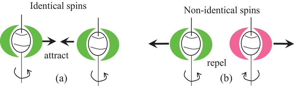
Postulate 8: Interactions between two ISpEFs. (a) Energy with the identical I-Spin attracts, and (b) non-identical spins repel each other.
5.2.5 Postulate 9, 10
However, the I-Spin field is a state of flux, and as a result, the spin state keeps constantly changing. The mutual repulsion between nonidentical I-Spin fields, at the generation, is the basis for initiation of the transmission of energy through free space.
The repulsion between the consecutive fields (Figure 8(b)) created in an entity/particle due to the change in its I-Spin initiates the energy fields moving outward from the origin. As shown in Figure 9, the initially produced δ-spin-field is pushed outward by the subsequently produced λ-spin field.

Postulate 8, 9: initiation of propagation of energy in free space. The traveling energy is initiated by the repulsiveness of the consecutive energy fields, which are non-identical, produced at the entity with varying spin. For example, the initially formed δ-spin-field is driven outward by the subsequently formed λ-spin-field.
In the I-Spin-field, energy is transmitted in the form of δ- and λ-field as against the EM wave of the classical theory.
Hence, a field train carrying energy in free space is formed.
The magnitude of I-Spin in a particle (or corresponding ISpEF) corresponds to the amplitude of the classical wave. The period of oscillation of the classical wave is interpreted here as the time of one complete spin cycle containing both δ-spin and λ-spin of the particle producing one energy cycle (unit cycle) in I-Spin.
5.2.6 Postulate 11
Any ISpEF created by a particle can impart its energy to any other particle it encounters in free space.
The rotation of I-Spin of entity X (Figure 10) produces alternating ISpEFs, and these ISpEFs move away, as shown in Figure 10. These ISpEFs induce corresponding I-Spins when they encounter entity Y on its path, as shown in Figure 10. When an entity is exposed to δ 0 (not shown but ahead of λ 0), it absorbs the energy and spins accordingly. Then, the particle Y simultaneously reemits the same/identical energy to free space as an ISpEF (δ 00) but with a delay due to the interaction. The delay depends on the properties of the interacting entity.

Postulate 10: ISpEF propagating through and the interaction of matter in free space. Entity Y absorbs energy δ 0 (not seen but ahead of λ 0) from the incoming ISpEF. This causes the entity Y to spin and simultaneously produces its own ISpEF (δ 00). The particle relays energy by receiving and retransmitting the ISpEF. However, the next approaching energy field has the opposite I-Spin (λ 0), which pushes away δ 00, as it propagates continually after emanating from the source.
Note that particle “X” is a hypothetical particle that does not exist. All particles act as a receiver and transmitter as the particle “Y.”
However, this ISpEF (δ 00) produced by Y is pushed away by the subsequent ISpEF (λ 0: red field in Figure 10) owing to the repulsive forces (Postulate 8). This is how the ISpEF propagates continually in the forward direction after it emanates from the source. The wave nature was first postulated by C. Huygens, who theorized that the light propagates as a wave front [60]. He further explained that, at any given instant, each point on the wave front is the origin of a secondary wave that propagates outward as a spherical wave. The secondary waves then combine to form a new wave front. However, the Huygens principle does not explain the unidirectional propagation of waves; according to the Huygens theory, a backward wave should be formed in the reverse direction [60,61]. Formation of backward wave was omitted in the Huygens theory [62]. However, postulate 11 in the ISpE model explains that once an energy propagation direction (δ-/λ-field direction) is established, it continues to propagate in the same direction though the I-Spin-field-train may transfer its energy into other particles (messenger particles) encountered on its way, thus there is no possibility of the reversing of direction of the field-train.
5.3 The absolute nature of the ISpEFs
It is already established that the I-Spin fields brought forward in this model are composed of δ-spin (dextro) and λ-spin (levo) as depicted earlier.
In a given I-Spin-field-train, the depicted δ-/λ-fields have their maximum values in magnitudes, but the real picture is that the field strengths continuously keep varying between their maximum values as the spinning entity is constantly changing its character as explained earlier.
Hence, the field is more exactly represented in a continuously changing nature of its spin and magnitude.
This could also explain the most fundamental experiment in optics [63], double-slit experiment (Supplementary data, Note 10), which described the wave nature of the energy propagation, conducted by Thomas Young in 1802.
Energy redistribution or interference (Supplementary Figure 10(a)) is not adequately explained in wave theory [64,65,66]. According to wave theory, the energy of an EM wave is associated with the electric field vector
E
and is proportional to
According to the superposition theorem, minima (zero-energy nodes) or destructive interference occurs in an interference when the electrical vectors of two EM waves are equal and opposite at that node. At the same time, maxima in interference carry an intensity that is four times the original intensity when both beams are coherent and identical in magnitude.
Although this energy redistribution is explained mathematically in the superposition theorem [67], it seems that the energy in minima has been depleted toward maxima (Figure 11). Since, according to the classical theory, the two E vectors with equal amplitudes have to be present at minima to ensure zero intensities at those regions, we arrive at an important problem as to whether the energies dissociate themselves from their E vectors at such zero nodes and moved toward maxima. It is clear that the energy in the dark region D moves/depletes and adds to the maxima (Figure 11), and this movement of energy is not explained in the classical wave theory.

Interference explained using the ISpE wave. The two components of an energy wave are denoted by violet and green. When two coherent waves meet, according to postulate 8 (Figure 8(a) and (b)), the area with the same ISpE (same color) attract and different I-Spins (different colors) repel each other. This results in energy redistribution or interference.
In the ISpE theory, when two coherent waves meet, according to Postulate 8, same spins (colors) are attracted to each other and form a maxima area, while unequal spins (colors) cannot exist at the same place due to repulsive nature and form a dark area. This results in energy displacement (or in classical theory, energy redistribution) in interference (see Figure 11). Therefore, the ISpE model can explain the energy displacement/redistribution in interference with greater clarity.
The energy propagates in the free space and inside matter. It is assumed that the energy propagates inside the matter similar to the free space. The only difference is the existence of particles in the matter compared with the free space. The energy propagation inside matter is still governed by all the postulates (especially Postulate 11) as matter also contains free space among particles.
The energy propagation occurring in an electric current is defined/interpreted as below.
5.4 Definition of electric current according to the proposed model
At any instant, ISpEFs travelling in opposite directions with opposite spins, within a confined space, produce an electric current.
It is defined that if there exist ISpEFs traveling in opposite directions with opposite I-Spins in a conductor at a given time and space (Figure 12(a)), electric current will be produced. The cross-sectional view of the distribution of ISpEF in a current-carrying conductor is shown in Figure 12(b). I-Spin fields, δ-field and λ-field, are arbitrarily assigned in the figure for the demonstration.

Definition of electric current: (a) instantaneous view of ISpEFs distributed inside a conductor. The ISpEFs are traveling in the same space in opposite directions with opposite I-Spins, the two I-Spins are far apart due to their repulsive nature. Most possible existence of mutually repulsive I-Spin fields in a conductor is at its circumference and at the center. (b) The cross-sectional view of the distribution of ISpEF in a current-carrying conductor.
Because of the repulsive nature of the two fields, most stable configuration would be one ISpE (either δ or λ) at the surface and the other at the center of the conductor. This is quite analogous to the magnetic field line distribution of a bar magnet or solenoid. The direction of the magnetic field inside the solenoid is opposite to the outside. The ISpE flow (or in current in classical terms) in the surface of the conductor could be identified as skin effect in classical definitions.
The proof of the center flow of ISpE (or current component in classical terms) can be proven by a separate experiment, and this experiment is described in the Supplementary data (Note 11).
The forces between two parallel conductors carrying current can also be explained in ISpF (Supplementary data, Note 12(i) and (ii)).
The current induced in a conductor due to a propagating ISpF in free space is also described in the Supplementary data (Note 13).
5.5 Explanation for the experimental observations in detailed study using ISpE concept
Description of two observations, Exp. II and Supplementary data, Note 3, using proposed I-Spin model is given in the Supplementary data, Note 14.
In summary, we have experimentally shown the presence of an induced current inside a perfect Faraday shield. As the classical wave theory fails to explain this phenomenon, an alternative theory (ISpE) was presented. We believe that this novel understanding of the manner in which energy is generated and subsequently transmitted through space would address the properties and aspects of the behavior of EM waves that could not be adequately explained using the classical EM theory. The ISpE model could lead to novel and more effective designs in many applications, such as photovoltaic cells used for solar energy harvesting, energy storage, EM shielding, and stealth technology.
6 Conclusion
This study demonstrates the existence of a current in a conductor placed within a Faraday shield, which is in apparent contradiction with the established classical EM theory. This investigation, based on the standard Faraday shield properties, has produced challenging observations inexplicable by the established EM theory. Both our preliminary study (Exp. I) and the detailed study (Exp. II) on field penetration have confronted us with the problem of accommodating with the established EM theory. Observations of the second experiment further indicated the contradictory nature to the existing knowledge of the energy and energy propagation in free space. Based on the observations, a new theory was presented with novel quantities, “spin-energy” and “spin-energy-field,” which are defined to replace the role of electric and magnetic fields in the classical EM theory. Using the proposed model, we were able to demonstrate comprehensively some physical phenomena comprising the propagation and interaction of energy with matter, including Young’s double-slit experiment, which provided the basis for the wave theory of light.
It is recognized that new concepts and theories contribute to the perpetuation of science in a big way. We have endeavored here to present the scientific world with a new idea: “the heuristic model of energy propagation in free space, based on the detection of a current induced in a conductor inside a continuously covered conducting enclosure by an external radio frequency source.”
The authors are convinced of the fact that this novel theory would form the basis of explaining many other associate physical phenomena with the introduction of the scientific community at large.
Acknowledgments
The experimental work was conducted at the Department of Electrical and Computer Engineering, University of Manitoba. Dr Piyadasa was financially supported by the Natural Sciences and Engineering Research Council (NSERC) of Canada. Duplication of the experiments was conducted and supported by the Sri Lanka Institute of Nanotechnology (SLINTEC). The financial support given by Harsha Subasinghe and the Codegen International Pvt Ltd is greatly acknowledged. The authors would also like to acknowledge H. Piyadasa and G. S. Palathirathna Wirasinha for their extensive edits to improve the quality of the manuscript.
References
[1] Young T. The Bakerian lecture: on the theory of light and colours. Philos Trans R Soc Lond. 1802;92:12–48.Suche in Google Scholar
[2] Planck M. Ueber irreversible Strahlungsvorgänge. Ann der Phys. 1900;306(1):69–122.10.1002/andp.19003060105Suche in Google Scholar
[3] Maxwell JC. A dynamical theory of the electromagnetic field. London: The Society; 1865. p. 459–512.10.5479/sil.423156.39088007130693Suche in Google Scholar
[4] Jackson JD. Classical electrodynamics. 3rd ed. New York: Wiley; 1999. xxi, p. 808.10.1119/1.19136Suche in Google Scholar
[5] Notaros BM. Electromagnetics. International ed. Upper Saddle River, N.J.; London: Pearson; 2011. p. 833.Suche in Google Scholar
[6] Ott HW, Ott HW. Electromagnetic compatibility engineering. Hoboken, New Jersey: John Wiley & Sons, Inc.; 2009. xxv, p. 843.10.1002/9780470508510Suche in Google Scholar
[7] Zahn M. Electromagnetic field theory: a problem solving approach. Reprint ed. Malabar, Fla.: Krieger Pub. Co.; 2003. xix, p. 723.Suche in Google Scholar
[8] Zakaria NA, Sudirman R, Jamaluddin MN, editors. Electromagnetic interference effect from power line noise in electrocardiograph signal using faraday cage. 2008 IEEE 2nd International Power and Energy Conference 2008. 1–3 Dec. 2008.10.1109/PECON.2008.4762559Suche in Google Scholar
[9] Wu JH, del Alamo JA. Design and modeling of Faraday cages for substrate noise isolation. Solid-State Electron. 2013;85:6–11.10.1016/j.sse.2013.03.005Suche in Google Scholar
[10] Lee BJ, Olcott PD, Key Jo H, Grant AM, Chen-Ming C, Levin CS, editors. Studies of electromagnetic interference of PET detector insert for simultaneous PET/MRI. 2013 IEEE Nuclear Science Symposium and Medical Imaging Conference (2013 NSS/MIC); 2013. Oct. 27 2013–Nov. 2 2013.Suche in Google Scholar
[11] Handel PH, George TF. 1/f Noise Inside a Faraday Cage. AIP Conf Proc. 2009;1129(1):491–4.10.1063/1.3140513Suche in Google Scholar
[12] Milián-Sánchez V, Mocholí-Salcedo A, Milián C, Kolombet VA, Verdú G. Anomalous effects on radiation detectors and capacitance measurements inside a modified Faraday cage. Nucl Instrum Meth Phys Res Sect A Accelerators Spectrometers Detect Associated Equip. 2016;828:210–28.10.1016/j.nima.2016.05.051Suche in Google Scholar
[13] Bethe HA. Theory of diffraction by small holes. Phys Rev. 1944;66(7/8):163–82.10.1103/PhysRev.66.163Suche in Google Scholar
[14] Cerri G, Leo RD, Primiani VM. Theoretical and experimental evaluation of the electromagnetic radiation from apertures in shielded enclosure. IEEE Trans Electromagn Compatibil. 1992;34(4):423–32.10.1109/15.179275Suche in Google Scholar
[15] Lei JZ, Liang CH, Zhang Y. Study on shielding effectiveness of metallic cavities with apertures by combining parallel FDTD method with windowing technique. Prog Electromagn Res. 2007;74:85–112.10.2528/PIER07041905Suche in Google Scholar
[16] Celozzi S, Araneo R, Lovat G. Electromagnetic shielding. Hoboken, NJ: Wiley-Interscience/IEEE Press; 2008. xii, p. 358.10.1002/9780470268483Suche in Google Scholar
[17] Chapman SJ, Hewett DP, Trefethen LN. Mathematics of the Faraday Cage. Siam Rev. 2015;57(3):398–417.10.1137/140984452Suche in Google Scholar
[18] McDowell AJ, Hubing TH. Analysis and comparison of plane wave shielding effectiveness decompositions. IEEE Trans Electromagn Compatibil. 2014;56(6):1711–4.10.1109/TEMC.2014.2332133Suche in Google Scholar
[19] Smullin LD. Design of tunable resonant cavities with constant bandwidth. Proc IRE. 1949;37(12):1442.10.1109/JRPROC.1949.230289Suche in Google Scholar
[20] Fresnel AJ, de Sénarmont HH, Verdet É, Fresnel LF. Œuvres complètes d’Augustin Fresnel: Théorie de la lumière. Paris: Imprimerie impériale; 1866.Suche in Google Scholar
[21] Kirchhoff G. Zur Theorie der Lichtstrahlen. Berlin: Reichsdruckerei; 1882.Suche in Google Scholar
[22] Longhurst RS. Geometrical and physical optics. 3rd ed. London: Longman; 1973. xviii, p. 677.Suche in Google Scholar
[23] Fowles GR. Introduction to modern optics. New York: Dover Publications; 1975.Suche in Google Scholar
[24] Hecht E, Zajac A. Optics. 2nd ed. Reading, Mass.: Addison-Wesley; 1987. x, p. 676.Suche in Google Scholar
[25] Maggi GA, Roberto PS, Volterra V. Sulla propagazione libera e perturbata delle onde luminose in un mezzo isotropo. 1871.Suche in Google Scholar
[26] Kumar R. Structure of boundary diffraction wave revisited. Appl Phys B 2007;90(3):379.10.1007/s00340-007-2897-ySuche in Google Scholar
[27] Gamini Piyadasa CK. Visualization of propagation of boundary diffraction wave. Eur Phys J D. 2011;64(2):505–9.10.1140/epjd/e2011-20176-2Suche in Google Scholar
[28] Piyadasa CKG. Detection of a cylindrical boundary diffraction wave emanating from a straight edge by light interaction. Opt Commun. 2012;285(24):4878–83.10.1016/j.optcom.2012.08.044Suche in Google Scholar
[29] Griffiths DJ. Introduction to electrodynamics. 3rd ed. Upper Saddle River, NJ; London: Prentice Hall; 1999. xv, p. 576.Suche in Google Scholar
[30] Kaiser KL. Electromagnetic Shielding. Boca Raton: Taylor & Francis; 2005.Suche in Google Scholar
[31] Paul CR. Introduction to electromagnetic compatibility. 2nd ed. Hoboken, NJ: Wiley-Interscience; 2006. xxi, p. 983.Suche in Google Scholar
[32] Williams T. EMC for Product Designers. Burlington: Elsevier Science; 2011.Suche in Google Scholar
[33] Hayt WH. Engineering electromagnetics. 4th ed. New York; London: McGraw Hill; 1981. xiii, p. 527.Suche in Google Scholar
[34] Lamb H. On electrical motions in a spherical conductor. Philos Trans R Soc Lond. 1883;174:519–49.10.1098/rstl.1883.0013Suche in Google Scholar
[35] Shen LC, Kong JA. Applied electromagnetism. 3rd ed. Boston, Mass./London: PWS/International Thomson Pub.; 1995. xiii, p. 606.Suche in Google Scholar
[36] Kaden H. Wirbelströme und Schirmung in der Nachrichtentechnik. In: Meissner W, editor. Verlag Berlin Heidelberg GmbH: Springer; 1959. p. 350.10.1007/978-3-540-32570-3Suche in Google Scholar
[37] Tesche FM. Electromagnetic field shielding of a spherical shell – revisited. Appl Comput Electromagnetics Soc Newsl. 2008;23(3):20.Suche in Google Scholar
[38] Gnecco LT. The design of shielded enclosures. Boston, Mass.: Newnes; 2000. p. 204.Suche in Google Scholar
[39] Balanis CA. Antenna theory: analysis and design. 3rd ed. Hoboken, NJ: Wiley-Interscience; 2005. xvii, p. 1117.Suche in Google Scholar
[40] Wald RM. General relativity. Chicago; London: University of Chicago Press; 1984. xiii, p. 491.10.7208/chicago/9780226870373.001.0001Suche in Google Scholar
[41] Kopp M. An introduction to HFSS: fundamental principles, concepts, and use. 225 West Station Square Drive, Suite 200 Pittsburgh, PA 152192009: Ansoft, LLC; 2009.Suche in Google Scholar
[42] Xiang Li YJ. Design of a cylindrical cavity resonator for measurments of electrical properties of dielectric materials. Masters thesis in electronic and telecommunications. University of Gavle; 2010.Suche in Google Scholar
[43] Das A, Das SK. Microwave Engineering. New Delhi: Tata McGraw-Hill Publishing Company; 2000.Suche in Google Scholar
[44] Cheng DK. Field and wave electromagnetics: solutions manual. 2nd ed. Reading, Massachusetts/Wokingham, England: Addison-Wesley Pub.; 1989. p. 147.Suche in Google Scholar
[45] Fujimoto M. Physics of classical electromagnetism. New York: Springer; 2007. Available from: http://rave.ohiolink.edu/ebooks/ebc/9780387680187.Suche in Google Scholar
[46] Kramer SL, Wang J-M. Beam induced RF cavity transient voltage1Work performed under the auspices of the U.S. Department of Energy. 1. Nucl Instrum Methods Phys Res Sect A Accelerators Spectrometers Detect Associated Equip. 1999;423(2):260–4.10.1016/S0168-9002(98)01369-2Suche in Google Scholar
[47] Poisel R. Antenna systems and electronic warfare applications. Boston, Mass/London: Artech House; 2012. xxiv, p. 1036.Suche in Google Scholar
[48] Eisberg RM, Resnick R. Quantum physics of atoms, molecules, solids, nuclei, and particles. 2nd ed. New York; Chichester: Wiley; 1985.Suche in Google Scholar
[49] Wald R. Gravitational Spin Interaction. Phys Rev D. 1972;6(2):406–13.10.1103/PhysRevD.6.406Suche in Google Scholar
[50] de Sabbata V, Sivaram C. Strong spin-torsion interaction between spinning protons. Il Nuovo Cimento A (1965–1970). 1989;101(2):273–83.10.1007/BF02813998Suche in Google Scholar
[51] Bonnor WB. Classical gravitational spin–spin interaction. Classical Quantum Gravity. 2002;19(1):143.10.1088/0264-9381/19/1/308Suche in Google Scholar
[52] Steinhoff J, Schäfer G. Comment on two recent papers regarding next-to-leading order spin-spin effects in gravitational interaction. Phys Rev D. 2009;80(8):088501.10.1103/PhysRevD.80.088501Suche in Google Scholar
[53] Pires AST. AdS/CFT correspondence in condensed matter. San Rafael: Morgan & Claypool Publishers; 2014. Available from: 10.1088/978-1-627-05309-9.Suche in Google Scholar
[54] Srednicki MA. Quantum field theory. Santha Barbara: University of California; xxi, p. 641.Suche in Google Scholar
[55] Beth RA. Mechanical detection and measurement of the angular momentum of light. Phys Rev. 1936;50(2):115–25.10.1887/0750309016/b1142c3Suche in Google Scholar
[56] Padgett M, Allen L. Light with a twist in its tail. Contemp Phys. 2000;41(5):275–85.10.1080/001075100750012777Suche in Google Scholar
[57] Stewart AM. Angular momentum of the electromagnetic field: the plane wave paradox resolved. Eur J Phys. 2005;26(4):635.10.1088/0143-0807/26/4/008Suche in Google Scholar
[58] de Broglie L. The reinterpretation of wave mechanics. Found Phys. 1970;1(1):5–15.10.1007/BF00708650Suche in Google Scholar
[59] Glazebrook R. Physical Optics. London: Longmans, Green; 1886.Suche in Google Scholar
[60] Huygens C. Traite de la lumiere: où sont expliquées les causes de ce qui luy arrive dans la réflexion, & dans la refraction; et particulièrement dans l’etrange réfraction du cristal d’Islande. Leide: Chez Pierre vander Aa; 1690. 4 p.l., p. 180.10.5479/sil.294285.39088000545160Suche in Google Scholar
[61] Heavens OS, Ditchburn RW. Insight into optics. Chichester: Wiley; 1991.Suche in Google Scholar
[62] Freegarde T. ebrary Inc. Introduction to the physics of waves. Cambridge; New York: Cambridge University Press; 2013. 1 online resource.Suche in Google Scholar
[63] Young T. II. The Bakerian Lecture. On the theory of light and colours. Philos Trans R Soc Lond. 1802;92:12–48.10.1098/rstl.1802.0004Suche in Google Scholar
[64] Piyadasa CKG. Redistribution of energy in electromagnetic wave interactions: interference of electromagnetic waves; a different approach. Sri Lankan J Phys. 2005;6:51–64.10.4038/sljp.v6i0.201Suche in Google Scholar
[65] Roychoudhuri C, Kracklauer AF, Creath K. The nature of light: what is a photon? Boca Raton: CRC Press; 2008. 1 online resource (xxi, 429 pages).Suche in Google Scholar
[66] Piyadasa CKG. Experimental observations of redistributed energy in wave interference. Opt – Int J Light Electron Opt. 2012;123(21):1988–92.10.1016/j.ijleo.2011.09.026Suche in Google Scholar
[67] Fowles GR. Introduction to modern optics. 2nd ed. New York: Holt, Rinehart and Winston; 1975. viii, p. 328.Suche in Google Scholar
© 2020 Chithra Kirthi Gamini Piyadasa et al., published by De Gruyter
This work is licensed under the Creative Commons Attribution 4.0 International License.
Artikel in diesem Heft
- Regular Articles
- Model of electric charge distribution in the trap of a close-contact TENG system
- Dynamics of Online Collective Attention as Hawkes Self-exciting Process
- Enhanced Entanglement in Hybrid Cavity Mediated by a Two-way Coupled Quantum Dot
- The nonlinear integro-differential Ito dynamical equation via three modified mathematical methods and its analytical solutions
- Diagnostic model of low visibility events based on C4.5 algorithm
- Electronic temperature characteristics of laser-induced Fe plasma in fruits
- Comparative study of heat transfer enhancement on liquid-vapor separation plate condenser
- Characterization of the effects of a plasma injector driven by AC dielectric barrier discharge on ethylene-air diffusion flame structure
- Impact of double-diffusive convection and motile gyrotactic microorganisms on magnetohydrodynamics bioconvection tangent hyperbolic nanofluid
- Dependence of the crossover zone on the regularization method in the two-flavor Nambu–Jona-Lasinio model
- Novel numerical analysis for nonlinear advection–reaction–diffusion systems
- Heuristic decision of planned shop visit products based on similar reasoning method: From the perspective of organizational quality-specific immune
- Two-dimensional flow field distribution characteristics of flocking drainage pipes in tunnel
- Dynamic triaxial constitutive model for rock subjected to initial stress
- Automatic target recognition method for multitemporal remote sensing image
- Gaussons: optical solitons with log-law nonlinearity by Laplace–Adomian decomposition method
- Adaptive magnetic suspension anti-rolling device based on frequency modulation
- Dynamic response characteristics of 93W alloy with a spherical structure
- The heuristic model of energy propagation in free space, based on the detection of a current induced in a conductor inside a continuously covered conducting enclosure by an external radio frequency source
- Microchannel filter for air purification
- An explicit representation for the axisymmetric solutions of the free Maxwell equations
- Floquet analysis of linear dynamic RLC circuits
- Subpixel matching method for remote sensing image of ground features based on geographic information
- K-band luminosity–density relation at fixed parameters or for different galaxy families
- Effect of forward expansion angle on film cooling characteristics of shaped holes
- Analysis of the overvoltage cooperative control strategy for the small hydropower distribution network
- Stable walking of biped robot based on center of mass trajectory control
- Modeling and simulation of dynamic recrystallization behavior for Q890 steel plate based on plane strain compression tests
- Edge effect of multi-degree-of-freedom oscillatory actuator driven by vector control
- The effect of guide vane type on performance of multistage energy recovery hydraulic turbine (MERHT)
- Development of a generic framework for lumped parameter modeling
- Optimal control for generating excited state expansion in ring potential
- The phase inversion mechanism of the pH-sensitive reversible invert emulsion from w/o to o/w
- 3D bending simulation and mechanical properties of the OLED bending area
- Resonance overvoltage control algorithms in long cable frequency conversion drive based on discrete mathematics
- The measure of irregularities of nanosheets
- The predicted load balancing algorithm based on the dynamic exponential smoothing
- Influence of different seismic motion input modes on the performance of isolated structures with different seismic measures
- A comparative study of cohesive zone models for predicting delamination fracture behaviors of arterial wall
- Analysis on dynamic feature of cross arm light weighting for photovoltaic panel cleaning device in power station based on power correlation
- Some probability effects in the classical context
- Thermosoluted Marangoni convective flow towards a permeable Riga surface
- Simultaneous measurement of ionizing radiation and heart rate using a smartphone camera
- On the relations between some well-known methods and the projective Riccati equations
- Application of energy dissipation and damping structure in the reinforcement of shear wall in concrete engineering
- On-line detection algorithm of ore grade change in grinding grading system
- Testing algorithm for heat transfer performance of nanofluid-filled heat pipe based on neural network
- New optical solitons of conformable resonant nonlinear Schrödinger’s equation
- Numerical investigations of a new singular second-order nonlinear coupled functional Lane–Emden model
- Circularly symmetric algorithm for UWB RF signal receiving channel based on noise cancellation
- CH4 dissociation on the Pd/Cu(111) surface alloy: A DFT study
- On some novel exact solutions to the time fractional (2 + 1) dimensional Konopelchenko–Dubrovsky system arising in physical science
- An optimal system of group-invariant solutions and conserved quantities of a nonlinear fifth-order integrable equation
- Mining reasonable distance of horizontal concave slope based on variable scale chaotic algorithms
- Mathematical models for information classification and recognition of multi-target optical remote sensing images
- Hopkinson rod test results and constitutive description of TRIP780 steel resistance spot welding material
- Computational exploration for radiative flow of Sutterby nanofluid with variable temperature-dependent thermal conductivity and diffusion coefficient
- Analytical solution of one-dimensional Pennes’ bioheat equation
- MHD squeezed Darcy–Forchheimer nanofluid flow between two h–distance apart horizontal plates
- Analysis of irregularity measures of zigzag, rhombic, and honeycomb benzenoid systems
- A clustering algorithm based on nonuniform partition for WSNs
- An extension of Gronwall inequality in the theory of bodies with voids
- Rheological properties of oil–water Pickering emulsion stabilized by Fe3O4 solid nanoparticles
- Review Article
- Sine Topp-Leone-G family of distributions: Theory and applications
- Review of research, development and application of photovoltaic/thermal water systems
- Special Issue on Fundamental Physics of Thermal Transports and Energy Conversions
- Numerical analysis of sulfur dioxide absorption in water droplets
- Special Issue on Transport phenomena and thermal analysis in micro/nano-scale structure surfaces - Part I
- Random pore structure and REV scale flow analysis of engine particulate filter based on LBM
- Prediction of capillary suction in porous media based on micro-CT technology and B–C model
- Energy equilibrium analysis in the effervescent atomization
- Experimental investigation on steam/nitrogen condensation characteristics inside horizontal enhanced condensation channels
- Experimental analysis and ANN prediction on performances of finned oval-tube heat exchanger under different air inlet angles with limited experimental data
- Investigation on thermal-hydraulic performance prediction of a new parallel-flow shell and tube heat exchanger with different surrogate models
- Comparative study of the thermal performance of four different parallel flow shell and tube heat exchangers with different performance indicators
- Optimization of SCR inflow uniformity based on CFD simulation
- Kinetics and thermodynamics of SO2 adsorption on metal-loaded multiwalled carbon nanotubes
- Effect of the inner-surface baffles on the tangential acoustic mode in the cylindrical combustor
- Special Issue on Future challenges of advanced computational modeling on nonlinear physical phenomena - Part I
- Conserved vectors with conformable derivative for certain systems of partial differential equations with physical applications
- Some new extensions for fractional integral operator having exponential in the kernel and their applications in physical systems
- Exact optical solitons of the perturbed nonlinear Schrödinger–Hirota equation with Kerr law nonlinearity in nonlinear fiber optics
- Analytical mathematical schemes: Circular rod grounded via transverse Poisson’s effect and extensive wave propagation on the surface of water
- Closed-form wave structures of the space-time fractional Hirota–Satsuma coupled KdV equation with nonlinear physical phenomena
- Some misinterpretations and lack of understanding in differential operators with no singular kernels
- Stable solutions to the nonlinear RLC transmission line equation and the Sinh–Poisson equation arising in mathematical physics
- Calculation of focal values for first-order non-autonomous equation with algebraic and trigonometric coefficients
- Influence of interfacial electrokinetic on MHD radiative nanofluid flow in a permeable microchannel with Brownian motion and thermophoresis effects
- Standard routine techniques of modeling of tick-borne encephalitis
- Fractional residual power series method for the analytical and approximate studies of fractional physical phenomena
- Exact solutions of space–time fractional KdV–MKdV equation and Konopelchenko–Dubrovsky equation
- Approximate analytical fractional view of convection–diffusion equations
- Heat and mass transport investigation in radiative and chemically reacting fluid over a differentially heated surface and internal heating
- On solitary wave solutions of a peptide group system with higher order saturable nonlinearity
- Extension of optimal homotopy asymptotic method with use of Daftardar–Jeffery polynomials to Hirota–Satsuma coupled system of Korteweg–de Vries equations
- Unsteady nano-bioconvective channel flow with effect of nth order chemical reaction
- On the flow of MHD generalized maxwell fluid via porous rectangular duct
- Study on the applications of two analytical methods for the construction of traveling wave solutions of the modified equal width equation
- Numerical solution of two-term time-fractional PDE models arising in mathematical physics using local meshless method
- A powerful numerical technique for treating twelfth-order boundary value problems
- Fundamental solutions for the long–short-wave interaction system
- Role of fractal-fractional operators in modeling of rubella epidemic with optimized orders
- Exact solutions of the Laplace fractional boundary value problems via natural decomposition method
- Special Issue on 19th International Symposium on Electromagnetic Fields in Mechatronics, Electrical and Electronic Engineering
- Joint use of eddy current imaging and fuzzy similarities to assess the integrity of steel plates
- Uncertainty quantification in the design of wireless power transfer systems
- Influence of unequal stator tooth width on the performance of outer-rotor permanent magnet machines
- New elements within finite element modeling of magnetostriction phenomenon in BLDC motor
- Evaluation of localized heat transfer coefficient for induction heating apparatus by thermal fluid analysis based on the HSMAC method
- Experimental set up for magnetomechanical measurements with a closed flux path sample
- Influence of the earth connections of the PWM drive on the voltage constraints endured by the motor insulation
- High temperature machine: Characterization of materials for the electrical insulation
- Architecture choices for high-temperature synchronous machines
- Analytical study of air-gap surface force – application to electrical machines
- High-power density induction machines with increased windings temperature
- Influence of modern magnetic and insulation materials on dimensions and losses of large induction machines
- New emotional model environment for navigation in a virtual reality
- Performance comparison of axial-flux switched reluctance machines with non-oriented and grain-oriented electrical steel rotors
- Erratum
- Erratum to “Conserved vectors with conformable derivative for certain systems of partial differential equations with physical applications”