Development of a generic framework for lumped parameter modeling
-
 and
and

Abstract
The purpose of this article is to present a generic reluctance network modeling tool dedicated to the modeling of electrical machines. This tool is used for the study of permanent magnet machines. The focus will be on the modeling methodology and software implementation. More precisely, the aspects related to genericity will be discussed. In order to validate the developed tool, the simulation of a 12 slot/10 pole flux-switching permanent magnet machine is conducted, and the results obtained from this generic framework are compared to the corresponding finite element analysis.
1 Introduction
The lumped parameter method (LPM) presents a good compromise between analytical methods, which are known for their reduced computation burden, and numerical methods, mainly the finite element method (FEM), which are known for their relatively good agreement with experimental measurements, when done with the minimum simplifying assumptions. The LPM helps reduce the computation time, while not increasing the number of simplifying assumptions. When used for the modeling of electromagnetic devices, the LPM is known as the magnetic equivalent circuit or the reluctance network (RN) [1,2]. In this contribution, efforts toward the development of a generic framework for the RN approach are presented. As finite element analysis (FEA), the first step in this framework is to mesh the studied domain using reluctance elements and then generate the corresponding algebraic equation system. The following steps are the solving of the generated equation system and exploitation of the obtained results for the analysis of the studied device.
Flux-switching permanent magnet (FSPM) machines are gaining in popularity due to their robustness, wide speed range, high torque, and high power density [3,4,5]. It is shown that FSPM machines have a higher air gap flux density due to the flux focusing effect and fewer mechanical issues in the rotor compared to surface permanent magnet (PM) machines [6]. However, the dual-salient structure results in higher harmonic orders of flux density in the air gap, which require a more refined mesh in FEA. Several studies [7,8,9] have presented a good agreement and a better performance of the mesh-based RN method used in FSPM machine computation, but they only focused on a limited aspect of global quantities, and the saturation is frequently ignored, which is a dominating phenomenon in FSPM machines. In this work, a generic framework for a mesh-based and interpolation coupled RN method is proposed, including a more programming oriented mathematical model and an extensible tool. Then, the global quantities of a 12 slot/10 pole FSPM machine are calculated using the tool. Compared to the method used in ref. [10], a mesh-based pre-processing and the application of the interpolation method on the motion interface avoid the specific knowledge of the investigated machines and increase the genericity of the RN method. Moreover, by using the connectivity matrix, a more programming-suitable formulation is obtained.
In the next sections, the framework will be more thoroughly described. The focus will be on the modeling methodology and software implementation. More precisely, the aspects related to genericity will be discussed. In order to validate the developed tool, the results obtained from this framework are compared to the corresponding FEA.
2 Framework presentation
Aspects related to the mathematical modeling and software implementation of the developed tool are discussed in Sections 2.1 and 2.2 in detail. Compared to previous studies on the subject, where the focus was on mathematical aspects and validation, efforts toward the building of a generic computational model are highlighted.
2.1 Mathematical model
The geometry is discretized in a number of bidirectional elementary reluctance blocks as shown in Figure 1. R x1, R x2, and R y1, R y2 are the reluctances on the x- and y-axis branches of the block element, respectively. Compared to previous studies, elements are allowed to be attached with two kinds of materials, which enables establishing a more precise model for sloping sides in machines.
where T x and T y are shape functions in the x- and y-direction, determined by the shape and size of elements. μ i and μ j are different permeabilities assigned to the element.
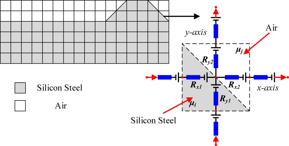
Reluctance block elements.
The circuit solver is developed based on Kirchhoff’s laws [11]. It can be established for a network containing N n nodes and N b branches as follows:
where Φ
B is the vector of the fluxes on branches,
According to Ohm’s law, Φ
B and
where U, P, and F are the voltage vector, the diagonal matrix of permeance, and the magneto-motive force (MMF) source vector, respectively. And the conversion between the voltage U and the node potential V can be expressed as:
Consequently, equation (2) is transformed into
MMF sources due to the PM need to be placed on the branches of the magnetization direction in the elements through all layers of PM areas, where each source is calculated as shown in equation (7) [12]. H c is the PM magnetic coercivity, and l mag is the length along the magnetization direction for each element (Figure 2).
To obey Ampere’s circuital law, MMF sources due to current need to model the distribution of MMF in the air gap first, which is a function of spatial position according to the winding distribution, denoted as F g(x,t). φ A(x), φ B(x), and φ C(x) are defined as the functions of MMF distribution in the air gap, when the unit current is provided for each phase. x is the x-axis coordinate of each element. Combining the spatial position function with the three-phase input current, we have
where F A, F B, and F C are the functions of MMF distribution changing with time. By summing them up, the expression of F g(x,t) is

Modeling of the PM unit.
Figure 3 shows the MMF distribution in the air gap, when setting t = 0 s, θ = 0°. Then, the MMF value contributed by each element should be calculated using the proportion to the whole current area at the corresponding point.
where h w is the height of the winding area and l l,e is the length along the magnetization direction for each element.

MMF distribution in the air gap.
The main principle of motion handling is to avoid regenerating the mesh in the studied domain with no or little compromise in precision. An interpolation method is employed here, based on the continuity of the scalar magnetic potential and the continuity of the flux density normal component at the sliding interface (Figure 4).
The subscripts s and r are used to denote the values from the stator side and the rotor side. Equation (11) shows a linear interpolation on the interface, and for the interpolation of k orders, the formulation is as follows:
By using the projection against a specific direction, we can obtain the normal component of the flux density of interface nodes from the connecting branch components.

Interface between the rotor and the stator.
Apart from the sliding interface, the RN is also defined by the Dirichlet boundary condition and the periodic or anti-periodic condition (Figure 5). For node n Dk , we have
For node i and node j, no matter what kind of boundary condition is assigned, they are viewed as adjacent elements, so they are connected by a branch, denoted as b. When using the periodic condition, we create the connectivity matrix as per the definition in equation (3). When using the anti-periodic condition, element C jb in the connectivity matrix is set to 1 rather than −1.

Boundary condition.
The Newton–Raphson method is a technique used for solving nonlinear equations numerically [13]. This method uses an iterative process to approach one root of a function, and this root depends on the initial value. For equation (2), we can write
knowing that
where operator
Branch b connects node i and node j, and by considering each part in two adjacent elements of a unique branch separately, the derivative of permeance with respect to node potentials is obtained from the corresponding components based on the expression of permeance calculation.
where l b is the length of branch b. Note that the Dirichlet boundary condition and interpolation formulation at the sliding interface modify some values in the coefficient matrix of linear equations, but they have no effect on the calculation of the Jacobian matrix. Accordingly, these items are set to zero after getting the Jacobian matrix using equation (13).
2.2 Tool structure
The framework is developed in four layers to provide genericity, flexibility, and extensibility (Figure 7). The frontal layer is a designing part serviced by widely used mesh tools. Apart from commercial software like ANSYS® and FLUXTM, GMSH is an open-source toolkit with a powerful and fast mesh function. In this study, an Excel worksheet constructed in a specific format that describes the structure of the machine is used as an input file (Figure 6).

Format of describing the structure of the machine in EXCEL.

Implementation of the tool.
Then, the framework reads the generated file into the circuit generator layer using an adaptor, which decodes the mesh information according to the pre-setting rules. The Excel worksheet in Figure 6 contains dimensions and confined mesh instructs for ExcelAdaptor to decide the concrete mesh scheme. DomainManager helps to manage the geometry properties of the studied domain and generate the size data for each element. Coupled with object Winding and object MaterialManager, DomainManager is processed by object CircuitGenerator, which provides the circuit descriptor encapsulating detailed information of branches that are required in object Assembler during iterations. MaterialManager offers the function of maintaining properties defined by users and helps to manage different types of materials especially nonlinear materials. Also, an interface is opened to accept the customer defined B–H curve fitting function. By default, the program uses an analytic saturation curve with knee adjustment.
where
The implementation of object Winding depends on different configurations of winding, which means that distributed windings and concentrated windings ought to be modeled in two ways. CircuitGenerator calls the unified interface to get the function F g(x,t) in the air gap when producing an MMF distribution model in the initial state to accelerate the solving process.
Figure 8 shows the main process of simulation at each time step in the circuit solver layer, when users launch a new analysis. Due to the nonlinear properties of materials, the circuit solver layer is developed in two types of iterative methods: fixed-point method and Newton–Raphson method. The Newton–Raphson method approaches a sufficiently precise value much faster than the fixed-point method because of using the tangent of the graph, but sometimes it is unable to reach a convergence as stable as the others. So in the program, both methods are provided. The construction of the Jacobian matrix has been described in the last section. The core solvers of fields are divided in single modules so that users are capable of building their own solver on these stable functions.

Process of the circuit solver layer.
The circuit solver layer inquires the upper layer to obtain the updated magnetic state through the specified interface at each step, which ensures the decoupling between two layers so that users are capable of designing their own modules by utilizing the well-encapsulated modules. Overloading of the default motion and boundary processing function is supported in the program, so a more effective motion handling method like the hybrid analytical method, which performs better in calculating the magnetic field in the air gap, is obtained.
All fields output by the circuit solver layer are registered in the DomainManager and exported to the CSV format, a type of file supported by many programs for post-processing.
3 Validation of the developed tool
In this section, a concrete validation study is described to highlight the good operation and correctness of the developed tool.
3.1 Structure presentation
The structure in Figure 9 is a classical 12/10 FSPM machine with concentrated windings, which has been analyzed in many previous cases. Although the dimensions of the machine were chosen to simplify the modeling study, the values can be set as any number in actual application. Table 1 gives the main machine characteristics.

Studied structure.
Machine parameters
| Mechanical air-gap (mm) | 0.35 |
| r so , r si , r ri (mm) | 128, 70.4, 22 |
| θ 1, θ 2, θ 3, θ 4 (°) | 7.5, 15, 7.5, 7.5 |
| l 1 (mm) | 4.6 |
| Magnetization type | Circumferential magnetization |
| PM magnetic remanence (T) | 1.12 |
| Axial length (mm) | 75 |
| Speed (rpm) | 480 |
| Peak current (A) | 10 |
| Coil turns | 70 |
3.2 Validation study
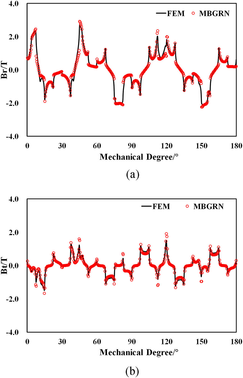
The comparisons shown in Figures 10–14 are between the FEM model meshed with 18,756 nodes and the RN model meshed with 4,800 nodes. Local quantities, such as the tangential and normal component of air gap flux density (Figures 10 and 12); global quantities, such as flux linkage and induced voltage versus time (Figures 11 and 13); torque; and iron loss (Figure 14) are evaluated by the classical method used in FEM. Flux linkage is the sum of fluxes (in the r-axis) passing through all block elements located at slot mid-height spanning one coil pitch. The electromotive force is obtained by the differentiation of the phase flux. The Maxwell stress tensor method is used for the computation of torque. For iron loss estimation, the experimentally verified iron loss model is used here [14]:
where P h, P c, and P e are, respectively, static hysteresis loss, classical eddy current loss, and excess loss; k h, k c, and k e are the coefficients of the corresponding loss component; f and B m are the frequency and amplitude of the fundamental flux density; and β is an empirical parameter obtained from experimental measurement.

Air-gap magnetic flux density component comparison, I m = 0 A. (a) Normal component and (b) tangential component.

Flux linkage and EMF comparison, I m = 0 A. (a) Flux linkage and (b) induced voltage.
Air-gap magnetic flux density component comparison, I m = 10 A. (a) Normal component and (b) tangential component.

Flux linkage and EMF comparison, I m = 10 A. (a) Flux linkage and (b) Induced voltage.

Torque and iron loss versus input current. (a) Torque versus current amplitude. (b) Iron loss versus current amplitude.
Errors of the proposed method compared to FEA
| I m (A) | Flux (error %) | Voltage (error %) | Torque (error %) | Iron loss (error %) |
|---|---|---|---|---|
| 0 | 1.22 | 1.25 | — | 1.03 |
| 10 | 1.56 | 1.78 | 2.48 | 2.25 |
As the FEA model is used as a reference, it is indicated that the RN model achieves a very good agreement with fewer nodes and faster computation speed. The errors of the flux linkages and the voltage waveforms could be obtained by comparing their RMS values obtained from both approaches, and the maximum error is lower than a few percent. For the torque and the core loss, the error is obtained by directly comparing the values of these quantities, and again the error is lower than a few percent (Table 2).
4 Conclusion
In this article, a generic calculating framework for lumped parameter modeling has been presented. The universal mathematical model has been put forward in the matrix format, based on which the structure of a flexible and extensible solver was discussed in detail. The adaptive mesh-based discretization and MMF source distribution techniques allow easy handling of different electromagnetic structures with different properties.
The interpolation method employed in modeling motion components avoids re-meshing at each time-step. Nonlinearities are considered in the solver, by combining the fixed-point method and the Newton–Raphson method. A fairly good agreement between the proposed tool and the commercial FEM software, in terms of flux density, flux linkage, induced voltage, torque, and loss, is obtained. It is a good step toward a powerful and easy-to-use RN tool in the pre-design stage.
Acknowledgments
The authors would like to thank the CNRS (GdR SEEDS 2994 du CNRS), National Natural Science Foundation of China under Grant no. 51825701, Key R&D Program of Jiangsu Province under Grant no. BE2019073, and Université Le Havre Normandie (GREAH) for the funding of this work.
References
[1] Ostovic V. Dynamics of saturated electric machines. New York: Springer-Verlag; 1989.10.1007/978-1-4613-8933-0Search in Google Scholar
[2] Amrhein M, Krein PT. 3-D magnetic equivalent circuit framework for modeling electromechanical devices. IEEE Trans Energy Convers. June 2009;24(2):397–405.10.1109/TEC.2009.2016134Search in Google Scholar
[3] Shao L, Hua W, Zhu ZQ, Zhu X, Cheng M, Wu Z. A novel flux-switching permanent magnet machine with overlapping windings. IEEE Trans Energy Convers. Mar. 2017;32(1):172–83.10.1109/TEC.2016.2611139Search in Google Scholar
[4] Zhu X, Shu Z, Quan L, Xiang Z, Pan X. Multi-objective optimization of an outer-rotor V-shaped permanent magnet flux switching motor based on multi-level design method. IEEE Trans Magn. Oct. 2016;52(10):1–8.10.1109/TMAG.2016.2581767Search in Google Scholar
[5] Hua W, Zhang H, Cheng M, Meng J, Hou C. An outer-rotor flux-switching permanent-magnet-machine with wedge-shaped magnets for in-wheel light traction. IEEE Trans Ind Electron. Jan. 2017;64(1):69–80.10.1109/TIE.2016.2610940Search in Google Scholar
[6] Liu M, Sixel W, Sarlioglu B. Comparative study of 6/4 FSPM and SPM machine for high-speed applications. 2019 IEEE Transportation Electrification Conference and Expo (ITEC). Detroit, MI, USA: 2019. p. 1–7.10.1109/ITEC.2019.8790622Search in Google Scholar
[7] Ouagued S, Amara Y, Barakat G. Comparison of hybrid analytical modelling and reluctance network modelling for pre-design purposes. Math Comp Simul. 2016;130:3–21.10.1016/j.matcom.2016.05.001Search in Google Scholar
[8] Lo DS, Lawali Ali H, Amara Y, Barakat G, Chabour F. Computation of cogging force of a linear tubular flux-switching permanent magnet machine using a hybrid analytical modeling. IEEE Trans Magn. Nov. 2018;54(11):1–5.10.1109/INTMAG.2018.8508771Search in Google Scholar
[9] Benhamida MA, Ennassiri H, Amara Y, Barakat G, Debbah N. Study of switching flux permanent magnet machines using interpolation based reluctance network model. 2016 International Conference on Electrical Sciences and Technologies in Maghreb (CISTEM), Marrakech, 2016. Nov. 2018. p. 1–7.110205.Search in Google Scholar
[10] Zhu ZQ, Pang Y, Howe D, Iwasaki S, Deodhar R, Pride A. Analysis of electromagnetic performance of flux-switching permanent-magnet machines by nonlinear adaptive lumped parameter magnetic circuit model. IEEE Trans Magnet. Nov. 2005;41(11):4277–87.10.1109/TMAG.2005.854441Search in Google Scholar
[11] Delale A, Albert L, Gerbaud L, Wurtz F. Automatic generation of sizing models for the optimization of electromagnetic devices using reluctance networks. IEEE Trans Magn. March 2004;2:830–3.10.1109/TMAG.2004.824908Search in Google Scholar
[12] Asfirane S, Hlioui S, Amara Y, Barriere ODL, Barakat G, Gabsi M. Global quantities computation using mesh-based generated reluctance networks. IEEE Trans Magnetics. Nov. 2018;54(11):1–4. Art 7002304.10.1109/INTMAG.2018.8508215Search in Google Scholar
[13] Yang X, Mittal R. Acceleration of the Jacobi iterative method by factors exceeding 100 using scheduled relaxation. J Comput Phys. October 2014;274:695–708.10.1016/j.jcp.2014.06.010Search in Google Scholar
[14] Lin D, Zhou P, Fu WN, Badics Z, Cendes ZJ. A dynamic core loss model for soft ferromagnetic and power ferrite materials in transient finite element analysis. IEEE Trans Magnet. March 2004;40(2):1318–21.10.1109/TMAG.2004.825025Search in Google Scholar
© 2020 Shuo Yang et al., published by De Gruyter
This work is licensed under the Creative Commons Attribution 4.0 International License.
Articles in the same Issue
- Regular Articles
- Model of electric charge distribution in the trap of a close-contact TENG system
- Dynamics of Online Collective Attention as Hawkes Self-exciting Process
- Enhanced Entanglement in Hybrid Cavity Mediated by a Two-way Coupled Quantum Dot
- The nonlinear integro-differential Ito dynamical equation via three modified mathematical methods and its analytical solutions
- Diagnostic model of low visibility events based on C4.5 algorithm
- Electronic temperature characteristics of laser-induced Fe plasma in fruits
- Comparative study of heat transfer enhancement on liquid-vapor separation plate condenser
- Characterization of the effects of a plasma injector driven by AC dielectric barrier discharge on ethylene-air diffusion flame structure
- Impact of double-diffusive convection and motile gyrotactic microorganisms on magnetohydrodynamics bioconvection tangent hyperbolic nanofluid
- Dependence of the crossover zone on the regularization method in the two-flavor Nambu–Jona-Lasinio model
- Novel numerical analysis for nonlinear advection–reaction–diffusion systems
- Heuristic decision of planned shop visit products based on similar reasoning method: From the perspective of organizational quality-specific immune
- Two-dimensional flow field distribution characteristics of flocking drainage pipes in tunnel
- Dynamic triaxial constitutive model for rock subjected to initial stress
- Automatic target recognition method for multitemporal remote sensing image
- Gaussons: optical solitons with log-law nonlinearity by Laplace–Adomian decomposition method
- Adaptive magnetic suspension anti-rolling device based on frequency modulation
- Dynamic response characteristics of 93W alloy with a spherical structure
- The heuristic model of energy propagation in free space, based on the detection of a current induced in a conductor inside a continuously covered conducting enclosure by an external radio frequency source
- Microchannel filter for air purification
- An explicit representation for the axisymmetric solutions of the free Maxwell equations
- Floquet analysis of linear dynamic RLC circuits
- Subpixel matching method for remote sensing image of ground features based on geographic information
- K-band luminosity–density relation at fixed parameters or for different galaxy families
- Effect of forward expansion angle on film cooling characteristics of shaped holes
- Analysis of the overvoltage cooperative control strategy for the small hydropower distribution network
- Stable walking of biped robot based on center of mass trajectory control
- Modeling and simulation of dynamic recrystallization behavior for Q890 steel plate based on plane strain compression tests
- Edge effect of multi-degree-of-freedom oscillatory actuator driven by vector control
- The effect of guide vane type on performance of multistage energy recovery hydraulic turbine (MERHT)
- Development of a generic framework for lumped parameter modeling
- Optimal control for generating excited state expansion in ring potential
- The phase inversion mechanism of the pH-sensitive reversible invert emulsion from w/o to o/w
- 3D bending simulation and mechanical properties of the OLED bending area
- Resonance overvoltage control algorithms in long cable frequency conversion drive based on discrete mathematics
- The measure of irregularities of nanosheets
- The predicted load balancing algorithm based on the dynamic exponential smoothing
- Influence of different seismic motion input modes on the performance of isolated structures with different seismic measures
- A comparative study of cohesive zone models for predicting delamination fracture behaviors of arterial wall
- Analysis on dynamic feature of cross arm light weighting for photovoltaic panel cleaning device in power station based on power correlation
- Some probability effects in the classical context
- Thermosoluted Marangoni convective flow towards a permeable Riga surface
- Simultaneous measurement of ionizing radiation and heart rate using a smartphone camera
- On the relations between some well-known methods and the projective Riccati equations
- Application of energy dissipation and damping structure in the reinforcement of shear wall in concrete engineering
- On-line detection algorithm of ore grade change in grinding grading system
- Testing algorithm for heat transfer performance of nanofluid-filled heat pipe based on neural network
- New optical solitons of conformable resonant nonlinear Schrödinger’s equation
- Numerical investigations of a new singular second-order nonlinear coupled functional Lane–Emden model
- Circularly symmetric algorithm for UWB RF signal receiving channel based on noise cancellation
- CH4 dissociation on the Pd/Cu(111) surface alloy: A DFT study
- On some novel exact solutions to the time fractional (2 + 1) dimensional Konopelchenko–Dubrovsky system arising in physical science
- An optimal system of group-invariant solutions and conserved quantities of a nonlinear fifth-order integrable equation
- Mining reasonable distance of horizontal concave slope based on variable scale chaotic algorithms
- Mathematical models for information classification and recognition of multi-target optical remote sensing images
- Hopkinson rod test results and constitutive description of TRIP780 steel resistance spot welding material
- Computational exploration for radiative flow of Sutterby nanofluid with variable temperature-dependent thermal conductivity and diffusion coefficient
- Analytical solution of one-dimensional Pennes’ bioheat equation
- MHD squeezed Darcy–Forchheimer nanofluid flow between two h–distance apart horizontal plates
- Analysis of irregularity measures of zigzag, rhombic, and honeycomb benzenoid systems
- A clustering algorithm based on nonuniform partition for WSNs
- An extension of Gronwall inequality in the theory of bodies with voids
- Rheological properties of oil–water Pickering emulsion stabilized by Fe3O4 solid nanoparticles
- Review Article
- Sine Topp-Leone-G family of distributions: Theory and applications
- Review of research, development and application of photovoltaic/thermal water systems
- Special Issue on Fundamental Physics of Thermal Transports and Energy Conversions
- Numerical analysis of sulfur dioxide absorption in water droplets
- Special Issue on Transport phenomena and thermal analysis in micro/nano-scale structure surfaces - Part I
- Random pore structure and REV scale flow analysis of engine particulate filter based on LBM
- Prediction of capillary suction in porous media based on micro-CT technology and B–C model
- Energy equilibrium analysis in the effervescent atomization
- Experimental investigation on steam/nitrogen condensation characteristics inside horizontal enhanced condensation channels
- Experimental analysis and ANN prediction on performances of finned oval-tube heat exchanger under different air inlet angles with limited experimental data
- Investigation on thermal-hydraulic performance prediction of a new parallel-flow shell and tube heat exchanger with different surrogate models
- Comparative study of the thermal performance of four different parallel flow shell and tube heat exchangers with different performance indicators
- Optimization of SCR inflow uniformity based on CFD simulation
- Kinetics and thermodynamics of SO2 adsorption on metal-loaded multiwalled carbon nanotubes
- Effect of the inner-surface baffles on the tangential acoustic mode in the cylindrical combustor
- Special Issue on Future challenges of advanced computational modeling on nonlinear physical phenomena - Part I
- Conserved vectors with conformable derivative for certain systems of partial differential equations with physical applications
- Some new extensions for fractional integral operator having exponential in the kernel and their applications in physical systems
- Exact optical solitons of the perturbed nonlinear Schrödinger–Hirota equation with Kerr law nonlinearity in nonlinear fiber optics
- Analytical mathematical schemes: Circular rod grounded via transverse Poisson’s effect and extensive wave propagation on the surface of water
- Closed-form wave structures of the space-time fractional Hirota–Satsuma coupled KdV equation with nonlinear physical phenomena
- Some misinterpretations and lack of understanding in differential operators with no singular kernels
- Stable solutions to the nonlinear RLC transmission line equation and the Sinh–Poisson equation arising in mathematical physics
- Calculation of focal values for first-order non-autonomous equation with algebraic and trigonometric coefficients
- Influence of interfacial electrokinetic on MHD radiative nanofluid flow in a permeable microchannel with Brownian motion and thermophoresis effects
- Standard routine techniques of modeling of tick-borne encephalitis
- Fractional residual power series method for the analytical and approximate studies of fractional physical phenomena
- Exact solutions of space–time fractional KdV–MKdV equation and Konopelchenko–Dubrovsky equation
- Approximate analytical fractional view of convection–diffusion equations
- Heat and mass transport investigation in radiative and chemically reacting fluid over a differentially heated surface and internal heating
- On solitary wave solutions of a peptide group system with higher order saturable nonlinearity
- Extension of optimal homotopy asymptotic method with use of Daftardar–Jeffery polynomials to Hirota–Satsuma coupled system of Korteweg–de Vries equations
- Unsteady nano-bioconvective channel flow with effect of nth order chemical reaction
- On the flow of MHD generalized maxwell fluid via porous rectangular duct
- Study on the applications of two analytical methods for the construction of traveling wave solutions of the modified equal width equation
- Numerical solution of two-term time-fractional PDE models arising in mathematical physics using local meshless method
- A powerful numerical technique for treating twelfth-order boundary value problems
- Fundamental solutions for the long–short-wave interaction system
- Role of fractal-fractional operators in modeling of rubella epidemic with optimized orders
- Exact solutions of the Laplace fractional boundary value problems via natural decomposition method
- Special Issue on 19th International Symposium on Electromagnetic Fields in Mechatronics, Electrical and Electronic Engineering
- Joint use of eddy current imaging and fuzzy similarities to assess the integrity of steel plates
- Uncertainty quantification in the design of wireless power transfer systems
- Influence of unequal stator tooth width on the performance of outer-rotor permanent magnet machines
- New elements within finite element modeling of magnetostriction phenomenon in BLDC motor
- Evaluation of localized heat transfer coefficient for induction heating apparatus by thermal fluid analysis based on the HSMAC method
- Experimental set up for magnetomechanical measurements with a closed flux path sample
- Influence of the earth connections of the PWM drive on the voltage constraints endured by the motor insulation
- High temperature machine: Characterization of materials for the electrical insulation
- Architecture choices for high-temperature synchronous machines
- Analytical study of air-gap surface force – application to electrical machines
- High-power density induction machines with increased windings temperature
- Influence of modern magnetic and insulation materials on dimensions and losses of large induction machines
- New emotional model environment for navigation in a virtual reality
- Performance comparison of axial-flux switched reluctance machines with non-oriented and grain-oriented electrical steel rotors
- Erratum
- Erratum to “Conserved vectors with conformable derivative for certain systems of partial differential equations with physical applications”