Comparative study of the thermal performance of four different parallel flow shell and tube heat exchangers with different performance indicators
-
Chulin Yu
 ,
Haiqing Zhang
,
Haiqing Zhang

Abstract
Round rod baffle (RRB), plain plate baffle (PPB), wavy-shaped plate baffle (WSB) and polygonal-shaped plate baffle (PSB) are four commonly used baffles in parallel flow shell and tube heat exchangers (STHXs). Comparative study of these four different baffles are numerically carried out using different performance indicators including Nusselt number, friction factor, performance evaluation criterion, entropy generation ratio, and entransy dissipation ratio for flow in full turbulent regime. Heat transfer mechanism has also been discussed. Correlations for Nusselt number and friction factor are fitted and the cost estimation using Hall’s method is compared. It is found that the Nusselt number of STHX-PPB, STHX-WSB, and STHX-PSB increased by 20.9%, 15.2%, and 23.9% averagely compared with STHX-RRB, respectively. The friction factor can be increased on average by 142.0%, 154.5%, and 242.4%, respectively. However, the overall performance of them is only 90.1%, 84.4%, and 82.3% that of STHX-RRB, respectively. The sequence of entropy generation and entransy dissipation is STHX-RRB > STHX-WSB > STHX-PPB > STHX-PSB. The inlet Re and baffle distance have significant effects on different performance indicators while the baffle width does not. Finally, the results show that the STHX-PSB can reduce the total cost as it has better ability on heat enhancement.
Nomenclature
- A
-
area (mm2)
- A in
-
area of cross-section (mm2)
- A b
-
area of blocked profile (mm2)
- a
-
length (mm)
- b
-
baffle width (mm)
- c
-
length (mm)
- c p
-
specific heat at constant pressure (J kg−1 K−1)
- c v
-
specific heat capacity at constant volume (J kg−1 K−1)
- C i
-
capital investment ($)
- C o
-
annual operating cost ($)
- C op
-
discounted operation cost ($)
- C tot
-
total cost ($)
- d i
-
inner tube diameter (mm)
- d o
-
outer tube diameter (mm)
- D h
-
hydraulic diameter (mm)
- f
-
average friction factor (–)
- h
-
convection heat transfer coefficient (W m2 K−1)
- L
-
length (mm)
- L b
-
baffle distance (mm)
- p
-
pressure (Pa)
- P t
-
tube pitch (mm)
- ΔT
-
log-mean temperature difference (K)
- T
-
temperature (K)
- t
-
thickness (mm)
- t b
-
baffle thickness (mm)
- u
-
velocity (m/s)
- V in
-
inlet velocity (m/s)
- Re
-
Reynolds number (–)
- R
-
radius (mm)
- Pr
-
Prandtl number (–)
- Δp
-
pressure drop (Pa)
- k el
-
price of electricity ($)
- H
-
hours of operation per year (h)
- V t
-
volume flow rate of tube side (m3/s)
- V s
-
volume flow rate of shell side (m3/s)
- Δp
-
pressure drop (Pa)
- Q
-
total wall heat flux (W m−2)
- Q tot
-
total heat duty (W)
- K
-
total heat transfer coefficient (W m2 K−1)
- S gen
-
entropy generation rate (W K−1)
- E diss
-
entransy dissipation (W K)
- P
-
pumping power (W)
- N s
-
entropy generation number
- n
-
number of tubes
- ζ
-
pump efficiency (–)
- δ
-
rate of annual discount (–)
- E C
-
Eckert number (–)
- St
-
Stanton number (–)
- m
-
mass flow rate (kg s−1)
Greek symbols
- ρ
-
density (kg m−3)
- ε
-
turbulence kinetic energy dissipation rate
- k
-
turbulence kinetic energy
- μ
-
dynamic viscosity (kg/m s)
- λ
-
thermal conductivity (W m−1 K−1)
- η
-
entropy generation number ratio
- γ
-
equivalent temperature difference (K)
- λ*
-
dimensionless length of the duct
- τ
-
dimensionless temperature difference
Subscripts
- w
-
wall
- in
-
inlet
- out
-
outlet
- i,j
-
tensor
- eff
-
effective term
- rod
-
round rod
- t
-
tube side
- s
-
shell side
- diss
-
dissipation
Abbreviations
- RRB
-
round rod baffle
- PPB
-
plain plate baffle
- WSB
-
wavy curve plate baffle
- PSB
-
polygonal curve plate baffle
- STHX
-
shell and tube heat exchanger
- PEC
-
performance evaluation criterion (–)
1 Introduction
Heat exchanger is a common equipment used in many industrial departments. Various heat exchangers are designed for different industry processes, in which more than 35–40% of heat exchangers used in industrial areas are shell and tube heat exchangers (STHXs) because of their easy maintenance and reliability [1]. In STHXs, the shape and arrangement of baffles are of essential importance for the thermal–hydraulic performance [2,3]. In the past decades, different types of new baffles are proposed to replace the traditional segmental baffle, such as rod baffle [4], plate baffle [5], ring baffle [6], and nonround orifice baffle [7]. Among these baffles, the round rod baffle (RRB) first proposed by Gentry [8] is widely used in different process industry because of its low pressure drop and high reliability.
In recent years, many researchers numerically and experimentally studied the thermal–hydraulic performance of different types of STHX-RRB. Wang et al. [9] experimentally investigated the heat transfer and flow performance of a double-shell pass rod baffle heat exchanger (DS-RBHX), the results revealed that the overall heat transfer performance of the DS-RBHX is higher than that of the single-shell pass RBHX (SS-RBHX). Liu et al. [10] numerically explored the radial distribution of coolants in the inlet section of rod baffle multitubular reactor. Results indicated that the radial distribution of coolants improved when the distance between the tube plate and the first rod baffle increased. Liu et al. [11] numerically learned the shell-side flow in STHX-RRB with spirally corrugated tubes. It was found that an efficiency evaluate coefficient of 1.35 can be obtained compared with the conventional STHX-RRB. Chen et al. [12] compared the thermal hydraulic performance of five heat exchangers that have different baffle patterns. They found that comprehensive performances of the rod baffle, tri-flower baffle, and pore plate baffle are better than that of the segmental baffle.
STHX-RRB was invented to overcome the problem of flow-induced tube vibration. In SHTX-RRB, baffles are constructed from an array of round support rods. The support rods are welded at each end to a baffle ring. The fluid in STHX-RRB flows in a direction parallel to the axis of the tubes. However, flow-induced tube vibration failure still can be found in some newly built STHX-RRB as can be seen from Figure 1 [13]. The reason can be summarized as follows: (1) cross flow inevitably existed at the inlet and outlet sections of the shell side, (2) a single rod can support a given tube only on one side. This makes the fundamental natural frequency of the tube supported by RRB lower than that of tube supported by segmental baffles if the same baffle distance is adopted, and (3) the rod is in point contact with the tube. As a result, the contact stress is so large resulting in an accelerating abrasion to the tube. In order to upgrade the antivibration ability of STHX-RRB, plain plate baffle (PPB) [14] was proposed by increasing the contact area between the tube and the baffle. Later, a wavy-shaped plate baffle (WSB) [15] was proposed by changing the line–surface contact to surface–surface contact. In the fourth-generation nuclear power station, polygonal-shapes plate baffle (PSB) [16] was extensively used to protect the tube from flow-induced vibration failure. A comparison view of STHX-RRB, STHX-PPB, STHX-WSB, and STHX-PSB is shown in Figure 2.
![Figure 1
Flow-induced tube vibration failure in STHX-RRB [14].](/document/doi/10.1515/phys-2020-0202/asset/graphic/j_phys-2020-0202_fig_001.jpg)
Flow-induced tube vibration failure in STHX-RRB [14].
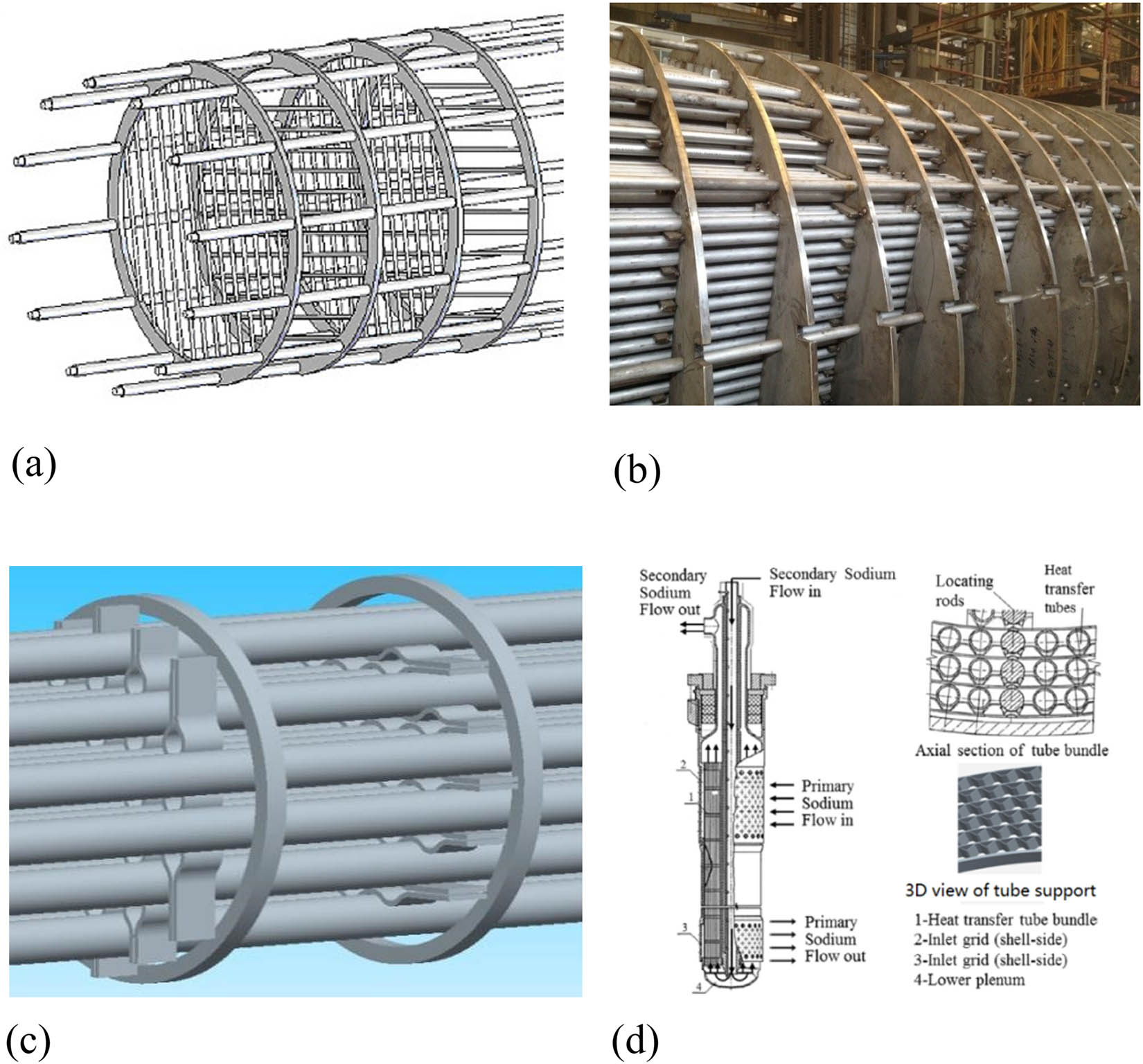
Sketch of (a) STHX-RRB, (b) STHX-PPB, (c) STHX-WSB and (d) STHX-PSB.
With the developing of computer technology, flow and heat transfer numerical simulation based on CFD is widely used to replace the experiments to explore the thermal performance of different heat exchangers. The flow unit duct model of STHX-RRB was widely used by many researchers [17,18,19]. Their results demonstrated that the unit duct model can be used to predict the heat transfer coefficient and pressure drop of STHX-RRB with a minimum requirement of computing resources.
In the past decades, various performance indicators are proposed to evaluate different design schemes of heat exchanger. The Nusselt number (Nu) and friction factor (f) are two commonly known performance indicators. Webb and Kim [20] deduced a performance indicator named performance evaluation criterion (PEC) based on the first law of thermodynamics to overcome the deficiency of single-way evaluation of Nu and f. If PEC > 1, it means that more heat can be transferred with the enhanced technology compared with the original one. Entropy generation [21] and entransy dissipation [22] are two different performance indicators based on the second law of thermodynamics. They can be used to weigh the irreversibility of different design schemes of heat exchangers.
Using different indicators to investigate the performance of system is a comprehensive method. Yu et al. [23] numerically explored the thermal–hydraulic performance of WSB and PSB. However, the formulas of thermal–hydraulic performance are not obtained. To the best of the authors’ knowledge, the study of STHX-RRB, STHX-PPB, STHX-WSB, and STHX-PSB using different performance indicators was not reported. In this article, a systematic analysis based on CFD is carried out to compare their different aspects. The effects of inlet Re, baffle distance, and baffle width on different performance indicators are discussed. Cost estimation using Hall’s method [24] is also compared. Finally, the heat transfer mechanism of four different STHXs is illustrated.
2 Geometrical models
For a tube bundle in nonstaggered alignment supported by RRB, PPB, WSB, or PSB, the corresponding profile of a repeated part (see the rectangle zone in Figure 3(a)) is shown in Figure 3(b)–(e), respectively. The geometrical parameters of different profiles are defined in Table 1. The blocked area ratios of these profiles are shown in Table 2.

(a) Schematic diagram of tube bundle in the non-staggered alignment supported by RRB, PPB, WSB or PSB. Detailed profile definition of (b) STHX-RRB, (c) STHX-PPB, (d) STHX-WSB and (e) STHX-PSB.
Geometrical parameters of different profiles
| Parameter | Value | Parameter | Value |
|---|---|---|---|
| d o (mm) | 25 | b (mm) | 10 |
| P t (mm) | 32 | c (mm) | 10 |
| R rod (mm) | 6 | R 1 (mm) | 10 |
| t b (mm) | 3 | R 2 (mm) | 7 |
| a (mm) | 10 | t (mm) | 6 |
Blocked area ratio of different profiles
| A in (mm2) | A b (mm2) | Ratio (%) | |
|---|---|---|---|
| STHX-RRB | 533.1 | 192 | 36 |
| STHX-PPB | 192 | 36 | |
| STHX-WSB | 212.9 | 39.9 | |
| STHX-PSB | 244.8 | 45.9 |
It can be seen from Figure 3 that the contact status between the tube and the baffle of STHX-RRB, STHX-PPB, STHX-WSB, and STHX-PSB is quite different. The RRB is in point contact with the tube, the PPB is in line contact with the tube, the WSB is in surface contact with the tube, and the PSB is in line contact with the tube. It is well-known that the contact stress is inversely proportional to the contact area when the contact force is fixed. This means that the contact stress between tube and baffle of STHX-RRB, STHX-PPB, STHX-WSB, and STHX-PSB follows the sequence of WSB < PSB < PPB < RRB. In addition, the WSB and PSB can support the tube at two directions. Thus, the fundamental natural frequency of tube supported by WSB or PSB is almost the same with that of tube supported by segmental baffles. This means that WSB and PSB have better ability to reduce the flow-induced tube vibration than PPB and RRB. Summing up the above two points, it can be recognized that the antivibration ability of these four different baffles follows the order of WSB > PSB > PPB > RRB.
3 Numerical model and computational scheme
3.1 Physical model
A periodic flow unit duct is taken as the simplified model of the shell side to perform numerical simulation by using Fluent. The following assumptions are made: (1) the working fluid is water with constant thermal properties (density ρ = 999.7 kg/m3, thermal conductivity λ = 0.574 W/(m K), specific heat C p = 4,191 (J/kg K), and μ = 0.001306 (Pa s)) remaining constant during the calculation process; (2) the fluid flow and heat transfer processes are turbulent and in steady state; (3) the heat exchanger is well insulated; (4) the viscous heating is neglected; and (5) the effect of gravity is negligible.
The actual length of the computational domain is four times the baffle distance plus 200 mm. That is, the length of the entrance section and exit section is equal to 100 mm and 100 mm to ensure the inlet uniformity and avoid outlet flow recirculating [25]. The schematic diagram of computational domain of STHX-RRB, STHX-PPB, STHX-WSB, and STHX-PSB is shown in Figure 4. The mesh of partial zoom out view of the selected baffle zone is shown in Figure 5.

Schematic diagram of computational domain of STHX-RRB, STHX-PPB, STHX-WSB and STHX-PSB.

Partial zoom out view of selected baffle zone of different unit duct mesh.
3.2 Numerical methods
The conservation equations of continuity, momentum, and energy for the turbulent heat transfer of fluid flowing on the shell side are presented in the tensor form as follows [26]:
Continuity equation:
Momentum equation:
Energy equation:
where T and p stand for fluid temperature and pressure, respectively; u is the fluid velocity;
For simple and fully developed turbulence cases, the standard k–ε turbulence model is applicable, and it is easier to converge than other turbulence models. Thus, standard k−ε turbulence model together with the standard wall function is adopted for the current computation. The conservation equations of turbulent kinetic energy and its dissipation rate are given below [27]:
For turbulence kinetic energy k:
For turbulence kinetic energy dissipation rate ε:
where
The constants for the current turbulent model are set as below:
The 3-D, double-precision, pressure-based solver is used. The nonslip boundary condition is adopted on all solid surfaces. The surfaces of the baffles are set as adiabatic. The velocity-inlet boundary condition and the pressure-outlet boundary condition are applied for the inlet and outlet, respectively. The other surfaces of the unit model are set as symmetry boundary conditions. SIMPLE algorithm is used for pressure–velocity coupling. The second-order upwind difference scheme is applied for energy and momentum computation. The second-order difference scheme is used for the pressure. The inlet bulk temperature is set as 283.15 K. The temperature of tube wall is set as a constant, 350 K. All equations take the convergent criteria of relative residual of 10−4 except energy taking 5 × 10⁻⁷.
3.3 Data reduction
Some formulas used in the postprocessing are defined as [28,29,30]:
3.4 Grid independence and code validation
In order to validate the solution independency of the grid, the grid dependency is checked for three different grids of STHX-RRB which have 2.2, 2.9, and 3.5 million cells, respectively. For the heat transfer coefficient, the error between the finest grid having 2.2 million cells and the grid having 3.5 million cells is less than 2% for the heat transfer coefficient and less than 3% for the friction coefficient. Therefore, the settings of the grid of the latter (3.5 million cells) are used for further investigations in the current study.
To validate the reliability of present numerical model, the results of nonstaggered tubes supported by RRB are compared with the data obtained by Dong et al. [17] the working fluid, the boundary conditions, and the baffle distance of them are all the same. The average Nu is plotted in Figure 6. For the unit model, it was found that the Nu was relatively smaller than the experimental data, especially in higher Reynolds number. This is mainly because the boundary is set as symmetry wall condition, thus there is no heat and mass transfer on that boundary in numerical calculation. While in fact there is plenty of turbulence and secondary flow leading to heat and mass transfer on the virtual boundary in the experiment. Figure 6 shows that the relative maximum deviation is within 16%. Such agreements show the reliability of the present physical model and numerical method.

The model validation of STHX-RRB.
3.5 Performance indicators
Based on the first law of thermodynamics, the transferred energy ratio under the same pump consumption can be evaluated using equation (13) [21].
Based on the second law of thermodynamics, the nondimensional entropy generation number ratio η can be used to weigh the irreversibility. For the problem presented in this article, the entropy generation of a duct with constant wall temperature is directly given below [22].
where
It is worth noting that if η < 1 and the smaller of the η, the better of the thermal–hydraulic performance and heat enhancement.
For the optimization of heat transfer process, a new physical quantity entransy dissipation extremum principle was proposed, which was initially referred to as the heat transfer potential capacity. For tube under uniform temperature condition, the entransy balance equation is directly given below [23].
It is deemed that the larger of γ, the more entransy dissipation, the more irreversibility of the heat transfer and the less heat can be transferred.
In this article, the abovementioned three performance indicators are used to compare the overall thermal–hydraulic performance of STHX-RRB, STHX-PPB, STHX-WSB, and STHX-PSB.
4 Results and discussions
4.1 Inlet Re effect
For Re in the range of 10,849–32,547, the variation in different performance indicators of STHX-RRB, STHX-PPB, STHX-WSB, and STHX-PSB is shown in Figure 7. The baffle distance is 200 mm. Other geometrical parameters of these four STHXs are the same with those listed in Table 1.
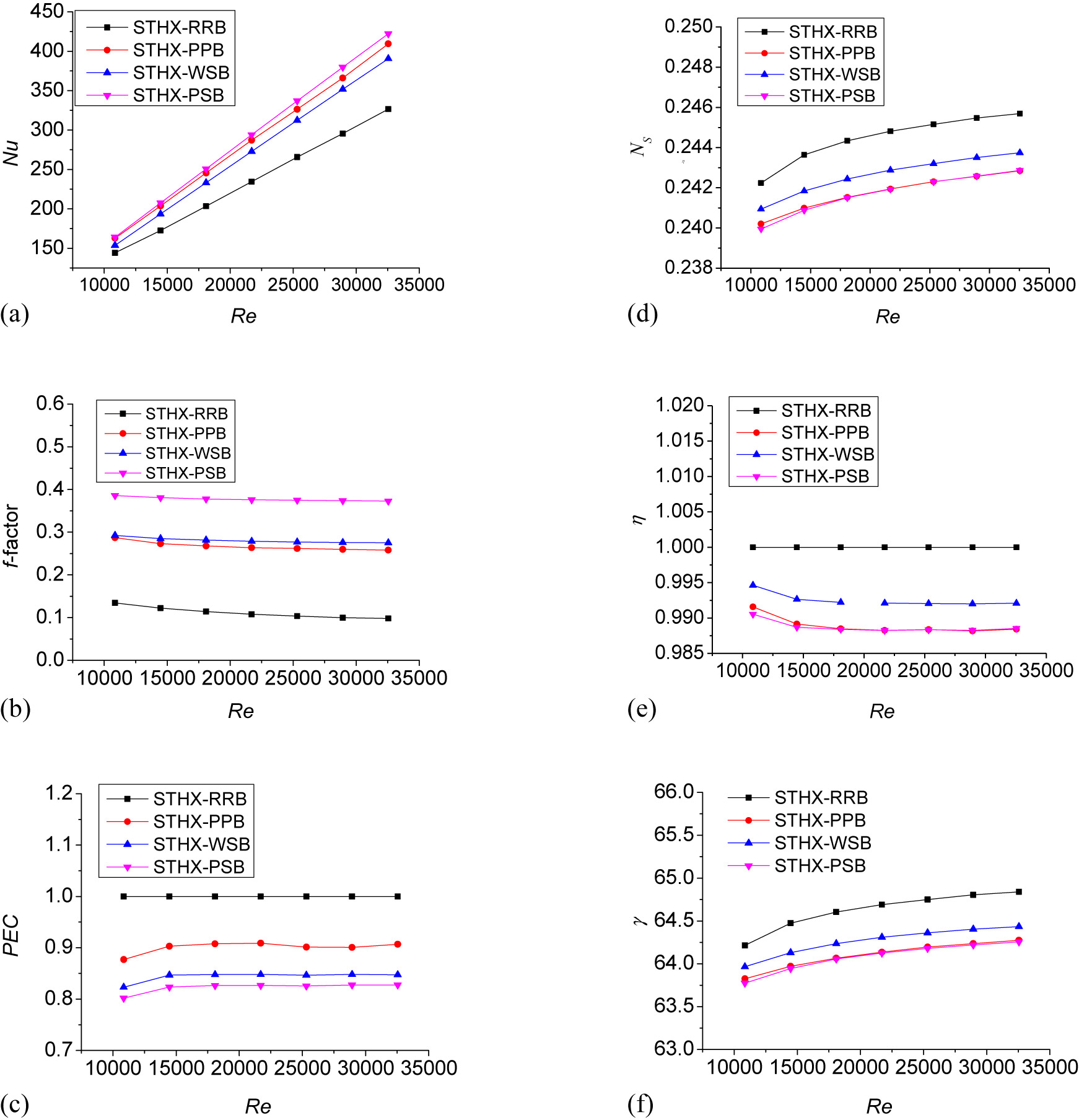
The effect of inlet Re on different performance indicators. (a) Nu comparisons for different Re, (b) f-factor comparisons for different Re, (c) PEC comparisons for different Re, (d) N s comparisons for different Re, (e) η comparisons for different Re, (f) γ comparisons for different Re.
Figure 7(a) shows that the Nu of STHX-RRB, STHX-PPB, STHX-WSB, and STHX-PSB increases with an increase in Re. The increasing rate is calculated based on the results of STHX-RRB. It can be found that the average increasing rate is 20.9% for STHX-PPB, 15.2% for STHX-WSB, and 23.9% for STHX-PSB. This indicates that the heat transfer enhancement ability order of STHX-RRB, STHX-PPB, STHX-WSB, and STHX-PSB is STHX-RRB < STHX-WSB < STHX-PPB < STHX-PSB.
Figure 7(b) shows that the f-factor of STHX-RRB, STHX-PPB, STHX-WSB, and STHX-PSB decreases with an increase in Re. Similarly, compared with STHX-RRB, it can be found that the average increasing rate is 142.0% for STHX-PPB, 154.6% for STHX-WSB, and 242.4% for STHX-PSB. This indicates that the power consumption order of STHX-RRB, STHX-PPB, STHX-WSB, and STHX-PSB is STHX-RRB < STHX-PPB < STHX-WSB < STHX-PSB.
Figure 7(c) shows that STHX-RRB has the largest PEC. The average PEC of STHX-PPB, STHX-WSB, and STHX-PSB is 90.1%, 84.4%, and 82.3% that of STHX-RRB. This indicates that the overall thermal–hydraulic performance order of STHX-RRB, STHX-PPB, STHX-WSB, and STHX-PSB is STHX-PSB < STHX-WSB < STHX-PPB < STHX-RRB. The reason why STHX-PPB has better overall thermal–hydraulic performance than STHX-WSB and STHX-PSB is that the pressure drop of STHX-PSB increases fast while the Nu of STHX-WSB increases slow.
Figure 7(d) and (e) shows the variations in N s and η with different Re. It can be found that the N s increases with an increase in Re. The N s and η of STHX-RRB, STHX-PPB, STHX-WSP, and STHX-PSP follow the order: STHX-PSB < STHX-PPB < STHX-WSP < STHX-RRB. This indicates that STHX-PSB has a better ability to reduce irreversibility compared to the other three. Therefore, STHX-PSB is recommended if minimum entropy generation is expected.
Figure 7(f) shows the variation in γ with different Re. It can be found that the γ increases with an increase in Re. The relative relation of γ between four different baffles is the same with those of N s and η. This implies that STHX-PSB can reduce irreversibility more effectively than others. This further proves the accuracy of entransy dissipation theory.
4.2 Baffle distance effect
For baffle distance is in the range of 110–350 mm; the variation in different performance indicators of STHX-RRB, STHX-PPB, STHX-WSB and STHX-PSB is shown in Figure 8. The inlet Re is 10,849 and other geometrical parameters of these four STHXs are the same as those listed in Table 1.

The effect of baffle distance on different performance indicators. (a) Nu comparisons for different baffle distance, (b) f-factor comparisons for different baffle distance, (c) N s comparisons for different baffle distance, (d) N s comparisons for different baffle distance, (e) η comparisons for different baffle distance, (f) γ comparisons for different baffle distance.
Figure 8(a) shows that the Nu decreases with an increase in baffle distance. The Nu of STHX-RRB, STHX-PPB, STHX-WSB, and STHX-PSB with a baffle distance of 110 mm is, respectively, 133%, 148.8%, 157%, and 157.4% times of those whose baffle distance is 350 mm. This indicates that the increase in baffle distance can significantly decrease the heat transfer rate. The reason is that an increased baffle distance would decrease the turbulence intensity of the jet flow along the flow passage.
Figure 8(b) shows that the f-factor decreases with an increase in baffle distance. The f-factor of STHX-RRB, STHX-PPB, STHX-WSB, and STHX-PSB with a baffle distance of 110 mm is, respectively, 243.2%, 312.7%, 320.7%, and 315.6% times of those whose baffle distance is 350 mm. This indicates that an increase in baffle distance can decrease the f-factor. This means that when RRB is replaced by PPB/WSB/PSB, the baffle distance should be enlarged to avoid excess pressure drop.
Figure 8(c) depicts the change in PEC versus baffle distance. It can be found that the PEC of STHX-PPB, STHX-WSB, and STHX-PSB follows the order of STHX-PSB < STHX-WSB < STHX-PPB at every baffle distance. Quantitatively, the PEC of STHX-PPB, STHX-WSB, and STHX-PSB is on average 87.7%, 83.7%, and 80.6% that of STHX-RRB over the investigated baffle distance. This means that the STHX-PPB has the best overall thermal–hydraulic performance among the above three.
Figure 8(d) and (e) shows the variations in N s and η in different baffle distance. It can be found that the N s decreases with an increase in baffle distance. The reason is that an increase in heat transfer area results in the reduction of irreversibility. In addition, it can be seen that the N s and η of STHX-RRB, STHX-PPB, STHX-WSP, and STHX- PSB follow the order: STHX-PSP < STHX-PPB < STHX-WSP < STHX-RRB. This further proves that STHX-PSB has a better ability to reduce irreversibility than the other three. Therefore, a relative larger baffle distance is recommended if a minimum entropy generation is expected.
Figure 8(f) shows that the variation in γ in different baffle distances. It can be found that the γ decreases with an increase in baffle distance, and the relative relation of the γ between four different baffles is similar to those of N s and η. This demonstrates that STHX-PSB is a more effective parallel flow baffle to reduce irreversibility compared to others.
4.3 Baffle width effect
Figure 3 shows that for STHX-PPB, STHX-WSB, and STHX-PSB, the contact area between baffle and tube increases with an increase in baffle width b. As a result, the contact stress between the baffle and tube decreases. In other words, the increase in baffle width is beneficial to antivibration ability.
For baffle width in the range of 10–30 mm, the variation in different performance indicators of STHX-PPB, STHX-WSB, and STHX-PSB is shown in Figure 9. The inlet Re is 10,849 and all other geometrical parameters of these three STHXs are the same as those listed in Table 1.

The effect of baffle width on different performance indicators. (a) Nu comparisons for different baffle width, (b) f-factor comparisons for different baffle width, (c) PEC comparisons for different baffle width, (d) N s comparisons for different baffle width, (e) η comparisons for different baffle width, (f) γ comparisons for different baffle width.
Figure 9(a) shows that the Nu increases with an increase in baffle width. The reason for this phenomenon is that with an increase in baffle width, the scope of zone with the smallest flow area also extended, which enhances the heat transfer and increases pressure drop. Besides, it can be seen that the Nu of STHX-PPB, STHX-WSB, and STHX-PSB with a baffle width of 30 mm is, respectively, on average 4.23%, 2.05%, and 3.97% higher than that with the baffle width of 10 mm. This means that the baffle width does not have a significant effect on the heat transfer characteristic.
Figure 9(b) shows that the f-factor increases with an increase in baffle width. It can be found that the f-factor of STHX-PPB, STHX-WSB, and STHX-PSB with a baffle width of 30 mm is, respectively, on average 8.22%, 13.01%, and 9.1% higher than that with baffle width of 10 mm. This means that baffle width has a significant effect on the pressure drop characteristic.
Figure 9(c) shows the changes in PEC under different baffle width. It can be found that the PEC does not monotonically increase or decrease with an increase in baffle width for every Re. The PEC of STHX-PPB and STHX-PSB with a baffle width of 30 mm is, respectively, on average 1.53% and 0.99% higher than that with baffle width of 10 mm. While the PEC of STHX-WSB with baffle width of 30 mm is −2.03% lower than that with baffle width of 10 mm. This means that an increase in the baffle width is beneficial in increasing the overall thermal–hydraulic performance of STHX-PPB and STHX-PSB while decreasing the baffle width is beneficial in increasing the overall thermal–hydraulic performance of STHX-WSB.
Figure 9(d) and (e) shows the changing tendency of N s and η in different baffle width. It can be found that the N s decreases with an increase in baffle width for a given Re. The reason is that increasing the baffle width results in the increase of the transferred heat. This indicates that increasing the baffle width can reduce irreversibility. Therefore, a relative large baffle width is recommended if a minimum entropy generation is expected.
Figure 9(f) shows that the variation in γ in different baffle width. It can be found that the γ increases with an increase in baffle width for a given Re. This result is consistent with the relationship between the entropy generation number and the baffle width.
4.4 Correlations for Nusselt number and friction factor
The Nu and f-factor correlations are fitted for STHX-RRB, STHX-PPB, STHX-WSB, and STHX-PSB. These correlations are shown in equations (18)–(25).
The adjusted residual square of the above fitted equations is 0.9963, 0.9995, 0.99936, 0.99909, 0.99863, 0.99893, 0.99904 and 0.99856. The above correlations are valid for Re in the range of 10,849–32,547, for baffle distance L b in the range of 110–350 mm and baffle width b in the range of 10–30 mm.
4.5 Cost comparison
In this section, cost comparison is carried out for an STHX with different parallel flow baffles. The input design parameters of the STHX are listed in Table 3. The basic geometric parameters of the STHX with different parallel flow baffles are listed in Table 4. The cost of STHX is calculated with Hall’s method [23,24]. Corresponding equations are listed in equations (26)–(36). Here we assume that the capital investment cost per area of STHX-RRB, STHX-PPB, STHX-WSB, and STHX-PSB is the same. The thermal resistance of tube wall and fouling thermal resistance are neglected. The value of ζ is 0.6. The cost comparison results are listed in Table 5.
where C tot is the total cost, C i is the capital investment cost, C op is the operating cost, A is the total tube outside the heat transfer area, elife is the equipment design life, δ is the rate of annual discount, k el is the price of electricity, H is the hours of operation per year, P is the pumping power, ζ is the pump efficiency, Δp t is the tube-side pressure drop, Δp s is the shell-side pressure drop, V t is the volume flow rate of tube side, and V s is the volume flow rate of shell side.
Design parameters of a parallel STHX
| Item | Value |
|---|---|
| Heat duty (MW) | 47.7 |
| Tube-side medium | Water |
| Shell-side medium | Water |
| Tube-side design pressure (MPa) | 15 |
| Shell-side design pressure (MPa) | 1 |
| Tube-side inlet temperature (K) | 360 |
| Tube-side outlet temperature (K) | 335 |
| Shell-side inlet temperature (K) | 283.15 |
| Shell-side outlet temperature (K) | 328 |
| Tube-side volume flow rate (m3/s) | 0.455 |
| Shell-side volume flow rate (m3/s) | 0.253 |
Basic geometric parameters of four different parallel flow STHXs
| Item | Value |
|---|---|
| Tube layout | Square |
| Tube diameter | 25 |
| Tube thickness | 2 |
| Tube pitch | 32 |
| No. of tubes | 659 |
| No. of tube pass | 1 |
| No. of shell pass | 1 |
| Shell’s inner diameter (mm) | 1,000 |
| Baffle distance (mm) | 200 |
Cost comparison of four different parallel flow STHXs
| Item | Unit | STHX-RRB | STHX-PPB | STHX-WSB | STHX-PSB |
|---|---|---|---|---|---|
| h t | W/m2 K | 10209.2 | 10209.2 | 10209.2 | 10209.2 |
| h s | W/m2 K | 3134.5 | 3828.9 | 3599.6 | 3888.1 |
| K | W/m2 K | 2854.9 | 3487.4 | 3278.5 | 3541.2 |
| A | m2 | 406.2 | 332.6 | 353.7 | 327.5 |
| L | m | 7.849 | 6.425 | 6.835 | 6.328 |
| Δp s | Pa | 5011.5 | 10133.4 | 10779.0 | 9979.2 |
| Δp t | Pa | 14114.6 | 12557.6 | 13005.4 | 12450.7 |
| C i | $ | 75981.2 | 65425.9 | 68494.3 | 64688.8 |
| C o | $ | 9622.0 | 10360.7 | 10820.3 | 10250.9 |
| C op | $ | 59,123.1 | 63661.8 | 66,485.8 | 62987.3 |
| C tot | $ | 135104.3 | 129087.7 | 134980.1 | 127676.1 |
It can be found from Table 5 that the C i sequence of these four parallel flow STHX is STHX-PSB < STHX-PPB < STHX-WSB < STHX-RRB. The reason is that the PSB can enhance heat transfer rate more effectively than the other three. The C op sequence is STHX-RRB < STHX-PSB < STHX-PPB < STHX-WSB. The reason is that the RRB has the smallest effect on pressure drop. The C tot sequence of these four parallel flow STHX is as follows: STHX-PSB < STHX-PPB < STHX-WSB < STHX-RRB. This means that STHX-PSB exhibits an obvious economic benefit compared with the other three. The reason is that STHX-PSB has a better effect on heat enhancement although the C op is the largest. Thus, the required total heat transfer area is also less. On the contrary, although the PEC of STHX-RRB is the largest, the heat enhancement is weak. Thus, the required total heat transfer area is large. This means that the STHX-PSB is recommended if the lowest total cost is expected for the design parameters given in Tables 3 and 4.
It is worth noting that cost estimation may be a more appropriate performance indicator than PEC, N s , and γ for designers. Because cost estimation can reflect the effect of design parameters of both shell side and tube side, PEC can only reflect the effect of parameters of one side (shell side in this article). The N s and γ are not intuitionistic for designers.
4.6 Heat transfer mechanism analysis
To better understand the heat transfer mechanism of STHX-RRB, STHX-PPB, STHX-WSB, and STHX-PSB, the 3D streamlines of them for inlet Re at 10,849 and baffle distance of 200 mm are plotted in Figure 10. The geometrical parameters of these four STHXs are the same as those listed in Table 1. The temperature variation in three cross-sections of the unit duct at position Z = 0.2 m, Z = 0 m, and Z = −0.2 m is shown in Figure 11. The field distribution contours on Y–Z plane are shown in Figure 12.

3D streamlines comparison of STHX-RRB, STHX-PPB, STHX-WSB and STHX-PSB.

Temperature contours comparisons of STHX-RRB, STHX-PPB, STHX-WSB and STHX-PSB at selected cross-sections.

The velocity, pressure and temperature contours of Y–Z plane of flow unit of STHX-RRB, STHX-PPB, STHX-WSB and STHX-PSB. (a) Velocity contour (m/s), (b) pressure contour (Pa), (c) temperature contour (K).
Figure 10 shows that the streamlines change their direction at the baffle zone. Some vortexes are generated at the back of the baffles. From Table 2, it can be found that the blocked area ratio order is as follow: STHX-PSB > STHX-WSB > STHX-PPB. Figure 10 shows that the velocity increasing rate order of STHX-RRB, STHX-PPB, STHX-WSB, and STHX-PSB at the baffle zone is the same as the blocked area ratio order mentioned above.
Figure 11 shows that, at cross-section Z = 0 m, the temperature of the water near the heated tube rises rapidly. However, an inner core no-heated region can also be seen in STHX-RRB and STHX-WSB. Furthermore, we can find that the no-heated zone in STHX-RRB is quite larger than that in STHX-WSB. This means that the working fluid in STHX-RRB shows a slower temperature rise compared with that in STHX-PPB, STHX-WSB, and STHX-PSB. This illustrates the low heat transfer capacity of STHX-RRB as demonstrated in Figure 7(a).
From Figure 12, we can find that the fluid velocity, pressure drop, and the temperature rapidly increase when the fluid flow passes the baffle. Meanwhile, the thickness of the boundary layer decreases. The variation in degree of velocity, pressure, and temperature follows an order of STHX-RRB < STHX-WSB < STHX-PPB < STHX-PSB. This further verifies the observation in Figure 10.
5 Conclusions
In this study, comparative study of the thermal performance of four different parallel STHXs is numerically explored with different performance indicators for Re in the range of 10,849–32,547. The antivibration ability of these four STHXs is analyzed. The effects of inlet Re, baffle distance, and baffle width on the performance indicators are discussed. Correlations for Nu and f-factor are fitted. Cost comparison using Hall’s method is also computed. Some main results show that:
The antivibration ability order is STHX-RRB < STHX-PPB < STHX-PSB < STHX-WSB, according to the contact area between the tube and baffle. This means that STHX-RRB should not be used in situation where the flow-induced tube vibration is serious. Instead, STHX-PSB and STHX-WSB are recommended.
The average Nu gain of STHX-PPB, STHX-WSB, and STHX-PSB is 20.9%, 15.2%, and 23.9%, respectively, compared with STHX-RRB for the investigated Re. The average f-factor increase in STHX-PPB, STHX-WSB, and STHX-PSB is 142.0%, 154.5%, and 242.4%, respectively, compared with STHX-RRB. The fast increase in f-factor results in the overall thermal–hydraulic performance of STHX-PPB, STHX-WSB, and STHX-PSB, which is only 90.1%, 84.4%, and 82.3% that of STHX-RRB.
The entropy generation and entransy dissipation order are STHX-RRB > STHX-WSB > STHX-PPB > STHX-PSB. This indicates that STHX-PSB has the best ability to reduce irreversibility.
The inlet Re and baffle distance have a significant effect on different performance indicators while the baffle width has a trivial effect.
STHX-PPB can achieve a good balance between different performance indicators. STHX-WSB is superior to STHX-PSB as it can obtain a better overall thermal–hydraulic performance and antivibration ability. However, STHX-PSB may exhibit a better economic value as it has a better effect on heat enhancement.
Acknowledgment
The work is supported by the National Science and Technology Major Project of China (No. 2010ZX06004). The authors are grateful for these supports.
References
[1] Master BI, Chunangad KS, Boxma AJ. Most frequently used heat exchangers from pioneering research to worldwide applications. Heat Transf Eng. 2006;27(6):4–11.10.1080/01457630600671960Search in Google Scholar
[2] Wang QW, Chen GD, Chen QY, Zeng M. Review of improvements on shell-and-tube heat exchangers with helical baffles. Heat Transf Eng. 2010;31(10):836–53.10.1080/01457630903547602Search in Google Scholar
[3] Thundil Karuppa Raj R, Ganne S. Shell side numerical analysis of a shell and tube heat exchanger considering the effects of baffle inclination angle on fluid flow. Therm Sci. 2012;16:1165–74.10.2298/TSCI110330118RSearch in Google Scholar
[4] Gu X, Dong XL, Liu MS. Numerical research on heat transfer and flow resistance performance of specially-shaped rod baffle heat exchangers. Heat Transf Asian Res. 2012;41:1–9.10.1002/htj.20388Search in Google Scholar
[5] Yang J, Liu W. Numerical investigation on a novel shell-and-tube heat exchanger with plate baffles and experimental validation. Energ Convers Manag. 2015;101:689–96.10.1016/j.enconman.2015.05.066Search in Google Scholar
[6] Deng XH, Deng SJ. Investigation of heat transfer enhancement of roughened tube bundles supported by ring or rod supports. Heat Transf Eng. 1998;19(2):21–7.10.1080/01457639808939917Search in Google Scholar
[7] Yang JF, Zeng M, Wang QW. Numerical investigation on combined single shell-pass shell-and-tube heat exchanger with two-layer continuous helical baffles. Int J Heat Mass Transf. 2015;84:103–13.10.1016/j.ijheatmasstransfer.2014.12.042Search in Google Scholar
[8] Gentry CC. Rod baffle heat exchanger technology. Chem Eng Prog. 1990;86(7):48–57.Search in Google Scholar
[9] Wang XT, Liang YM, Sun Y, Liu ZC, Liu W. Experimental and numerical investigation on shell-side performance of a double shell-pass rod baffle heat exchanger. Int J Heat Mass Tran. 2019;132:631–42.10.1016/j.ijheatmasstransfer.2018.12.046Search in Google Scholar
[10] Liu C, Zhang L, Xu YK. CFD study on the radial distribution of coolants in the inlet section of rod-baffle-multi-tubular reactor. Korean J Chem Eng. 2017;34:651–63.10.1007/s11814-016-0133-3Search in Google Scholar
[11] Liu JJ, Liu ZC, Liu W. 3D numerical study on shell side heat transfer and flow characteristics of rod-baffle heat exchangers with spirally corrugated tubes. Int J Therm Sci. 2015;89:34–42.10.1016/j.ijthermalsci.2014.10.011Search in Google Scholar
[12] Chen J, Li NQ, Ding Y, Klemes JJ, Varbanov PS, Wang QW, et al. Experimental thermal-hydraulic performances of heat exchangers with different baffle patterns. Energy. 2020;205:118066.10.1016/j.energy.2020.118066Search in Google Scholar
[13] Liu YQ, Cao DH, Wang J. Tube bundle wearing problem of large Rod baffle heat exchanger. Chin Plant Eng. 2017;15:103–4 (in Chinese).Search in Google Scholar
[14] Hu MF, Yang BT, Qi DH. Vibration characteristic of heat exchanger with anti-vibration plate clamping baffle. Chem Machine. 1999;26:196–9 (in Chinese).Search in Google Scholar
[15] Li J, Liu MS, Dong QW. Numerical research of new anti-vibration baffle of heat exchanger with longitudinal flow of shellside. J Eng Therm Energ Power. 2005;20(6):579–83 (in Chinese).Search in Google Scholar
[16] Zhang XL, Tseng PC, Saeed M, Yu JY. A CFD based simulation of fluid flow and heat transfer in intermediate heat exchanger of sodium-cooled fast reactor. Ann Nucl Energ. 2017;109:529–37.10.1016/j.anucene.2017.05.063Search in Google Scholar
[17] Dong QW, Wang YQ, Liu MS. Numerical and experimental investigation of shellside characteristics for RODbaffle heat exchanger. Appl Therm Eng. 2008;28:651–60.10.1016/j.applthermaleng.2007.06.038Search in Google Scholar
[18] Li NQ, Chen J, Cheng T, Klemes JJ, Varbanov PS, Wang QW, et al. Analysing thermal-hydraulic performance and energy efficiency of shell-and-tube heat exchangers with longitudinal flow based on experiment and numerical simulation. Energy. 2020;202:117757.10.1016/j.energy.2020.117757Search in Google Scholar
[19] Yang J, Ma L, Bock J. A comparison of four numerical modeling approaches for enhanced shell-and-tube heat exchangers with experimental validation. Appl Therm Eng. 2014;65:369–83.10.1016/j.applthermaleng.2014.01.035Search in Google Scholar
[20] Webb RL, Kim NH. Principle of enhanced heat transfer. New York, NY, USA: Taylor Francis; 1994.Search in Google Scholar
[21] Zheng NB, Liu P, Shan F, Liu ZC, Liu W. Numerical investigations of the thermal-hydraulic performance in a rib-grooved heat exchanger tube based on entropy generation analysis. Appl Therm Eng. 2016;99:1071–85.10.1016/j.applthermaleng.2016.02.008Search in Google Scholar
[22] Zheng NB, Liu P, Shan F, Liu ZC, Liu W. Effects of rib arrangements on the flow pattern and heat transfer in an internally ribbed internally ribbed heat exchanger tube. Int J Therm Sci. 2016;101:93–105.10.1016/j.ijthermalsci.2015.10.035Search in Google Scholar
[23] Yu CL, Ren ZW, Zeng M. Numerical investigation of shell-side performance for shell and tube heat exchangers with two different clamping type anti-vibration baffles. Appl Therm Eng. 2018;133:125–36.10.1016/j.applthermaleng.2018.01.029Search in Google Scholar
[24] Hadidi A, Nazari A. Design and economic optimization of shell-and-tube heat exchangers using biogeography-based (BBO) algorithm. Appl Therm Eng. 2013;51:1263–72.10.1016/j.applthermaleng.2012.12.002Search in Google Scholar
[25] Zeng M, Tang LH, Lin M, Wang QW. Optimization of heat exchangers with vortex-generator fin by Taguchi method. Appl Therm Eng. 2010;30:1775–83.10.1016/j.applthermaleng.2010.04.009Search in Google Scholar
[26] FLUENT user’s guide. New York: Fluent Inc.; 2003.Search in Google Scholar
[27] Sarma PK, Subramanyam T, Kishore PS, Dharma Rao V, Kakac S. Laminar convective heat transfer with twisted tape inserts in a tube. Int J Therm Sci. 2003;42:9.10.1016/S1290-0729(03)00055-3Search in Google Scholar
[28] Wang W, Fu K, Zhang YN, Tan YF, Li BX, Sunden B. Entropy study on the enhanced heat transfer mechanism of the coupling of detached and spiral vortex fields in spirally corrugated tubes. Heat Transf Eng. 2020;42:1–15.10.1080/01457632.2020.1800251Search in Google Scholar
[29] Wang W, Zhang YN, Lee WOO, Li BX. Optimal design of a double pipe heat exchanger based on the outward helically corrugated tube. Int J Heat Mass Tran. 2019;135:706–16.10.1016/j.ijheatmasstransfer.2019.01.115Search in Google Scholar
[30] Wang W, Zhang YN, Liu J, Li BX, Sunden B. Numerical investigation of entropy generation of turbulent flow in a novel outward corrugated tube. Int J Heat Mass Tran. 2018;126:836–47.10.1016/j.ijheatmasstransfer.2018.06.017Search in Google Scholar
© 2020 Chulin Yu et al., published by De Gruyter
This work is licensed under the Creative Commons Attribution 4.0 International License.
Articles in the same Issue
- Regular Articles
- Model of electric charge distribution in the trap of a close-contact TENG system
- Dynamics of Online Collective Attention as Hawkes Self-exciting Process
- Enhanced Entanglement in Hybrid Cavity Mediated by a Two-way Coupled Quantum Dot
- The nonlinear integro-differential Ito dynamical equation via three modified mathematical methods and its analytical solutions
- Diagnostic model of low visibility events based on C4.5 algorithm
- Electronic temperature characteristics of laser-induced Fe plasma in fruits
- Comparative study of heat transfer enhancement on liquid-vapor separation plate condenser
- Characterization of the effects of a plasma injector driven by AC dielectric barrier discharge on ethylene-air diffusion flame structure
- Impact of double-diffusive convection and motile gyrotactic microorganisms on magnetohydrodynamics bioconvection tangent hyperbolic nanofluid
- Dependence of the crossover zone on the regularization method in the two-flavor Nambu–Jona-Lasinio model
- Novel numerical analysis for nonlinear advection–reaction–diffusion systems
- Heuristic decision of planned shop visit products based on similar reasoning method: From the perspective of organizational quality-specific immune
- Two-dimensional flow field distribution characteristics of flocking drainage pipes in tunnel
- Dynamic triaxial constitutive model for rock subjected to initial stress
- Automatic target recognition method for multitemporal remote sensing image
- Gaussons: optical solitons with log-law nonlinearity by Laplace–Adomian decomposition method
- Adaptive magnetic suspension anti-rolling device based on frequency modulation
- Dynamic response characteristics of 93W alloy with a spherical structure
- The heuristic model of energy propagation in free space, based on the detection of a current induced in a conductor inside a continuously covered conducting enclosure by an external radio frequency source
- Microchannel filter for air purification
- An explicit representation for the axisymmetric solutions of the free Maxwell equations
- Floquet analysis of linear dynamic RLC circuits
- Subpixel matching method for remote sensing image of ground features based on geographic information
- K-band luminosity–density relation at fixed parameters or for different galaxy families
- Effect of forward expansion angle on film cooling characteristics of shaped holes
- Analysis of the overvoltage cooperative control strategy for the small hydropower distribution network
- Stable walking of biped robot based on center of mass trajectory control
- Modeling and simulation of dynamic recrystallization behavior for Q890 steel plate based on plane strain compression tests
- Edge effect of multi-degree-of-freedom oscillatory actuator driven by vector control
- The effect of guide vane type on performance of multistage energy recovery hydraulic turbine (MERHT)
- Development of a generic framework for lumped parameter modeling
- Optimal control for generating excited state expansion in ring potential
- The phase inversion mechanism of the pH-sensitive reversible invert emulsion from w/o to o/w
- 3D bending simulation and mechanical properties of the OLED bending area
- Resonance overvoltage control algorithms in long cable frequency conversion drive based on discrete mathematics
- The measure of irregularities of nanosheets
- The predicted load balancing algorithm based on the dynamic exponential smoothing
- Influence of different seismic motion input modes on the performance of isolated structures with different seismic measures
- A comparative study of cohesive zone models for predicting delamination fracture behaviors of arterial wall
- Analysis on dynamic feature of cross arm light weighting for photovoltaic panel cleaning device in power station based on power correlation
- Some probability effects in the classical context
- Thermosoluted Marangoni convective flow towards a permeable Riga surface
- Simultaneous measurement of ionizing radiation and heart rate using a smartphone camera
- On the relations between some well-known methods and the projective Riccati equations
- Application of energy dissipation and damping structure in the reinforcement of shear wall in concrete engineering
- On-line detection algorithm of ore grade change in grinding grading system
- Testing algorithm for heat transfer performance of nanofluid-filled heat pipe based on neural network
- New optical solitons of conformable resonant nonlinear Schrödinger’s equation
- Numerical investigations of a new singular second-order nonlinear coupled functional Lane–Emden model
- Circularly symmetric algorithm for UWB RF signal receiving channel based on noise cancellation
- CH4 dissociation on the Pd/Cu(111) surface alloy: A DFT study
- On some novel exact solutions to the time fractional (2 + 1) dimensional Konopelchenko–Dubrovsky system arising in physical science
- An optimal system of group-invariant solutions and conserved quantities of a nonlinear fifth-order integrable equation
- Mining reasonable distance of horizontal concave slope based on variable scale chaotic algorithms
- Mathematical models for information classification and recognition of multi-target optical remote sensing images
- Hopkinson rod test results and constitutive description of TRIP780 steel resistance spot welding material
- Computational exploration for radiative flow of Sutterby nanofluid with variable temperature-dependent thermal conductivity and diffusion coefficient
- Analytical solution of one-dimensional Pennes’ bioheat equation
- MHD squeezed Darcy–Forchheimer nanofluid flow between two h–distance apart horizontal plates
- Analysis of irregularity measures of zigzag, rhombic, and honeycomb benzenoid systems
- A clustering algorithm based on nonuniform partition for WSNs
- An extension of Gronwall inequality in the theory of bodies with voids
- Rheological properties of oil–water Pickering emulsion stabilized by Fe3O4 solid nanoparticles
- Review Article
- Sine Topp-Leone-G family of distributions: Theory and applications
- Review of research, development and application of photovoltaic/thermal water systems
- Special Issue on Fundamental Physics of Thermal Transports and Energy Conversions
- Numerical analysis of sulfur dioxide absorption in water droplets
- Special Issue on Transport phenomena and thermal analysis in micro/nano-scale structure surfaces - Part I
- Random pore structure and REV scale flow analysis of engine particulate filter based on LBM
- Prediction of capillary suction in porous media based on micro-CT technology and B–C model
- Energy equilibrium analysis in the effervescent atomization
- Experimental investigation on steam/nitrogen condensation characteristics inside horizontal enhanced condensation channels
- Experimental analysis and ANN prediction on performances of finned oval-tube heat exchanger under different air inlet angles with limited experimental data
- Investigation on thermal-hydraulic performance prediction of a new parallel-flow shell and tube heat exchanger with different surrogate models
- Comparative study of the thermal performance of four different parallel flow shell and tube heat exchangers with different performance indicators
- Optimization of SCR inflow uniformity based on CFD simulation
- Kinetics and thermodynamics of SO2 adsorption on metal-loaded multiwalled carbon nanotubes
- Effect of the inner-surface baffles on the tangential acoustic mode in the cylindrical combustor
- Special Issue on Future challenges of advanced computational modeling on nonlinear physical phenomena - Part I
- Conserved vectors with conformable derivative for certain systems of partial differential equations with physical applications
- Some new extensions for fractional integral operator having exponential in the kernel and their applications in physical systems
- Exact optical solitons of the perturbed nonlinear Schrödinger–Hirota equation with Kerr law nonlinearity in nonlinear fiber optics
- Analytical mathematical schemes: Circular rod grounded via transverse Poisson’s effect and extensive wave propagation on the surface of water
- Closed-form wave structures of the space-time fractional Hirota–Satsuma coupled KdV equation with nonlinear physical phenomena
- Some misinterpretations and lack of understanding in differential operators with no singular kernels
- Stable solutions to the nonlinear RLC transmission line equation and the Sinh–Poisson equation arising in mathematical physics
- Calculation of focal values for first-order non-autonomous equation with algebraic and trigonometric coefficients
- Influence of interfacial electrokinetic on MHD radiative nanofluid flow in a permeable microchannel with Brownian motion and thermophoresis effects
- Standard routine techniques of modeling of tick-borne encephalitis
- Fractional residual power series method for the analytical and approximate studies of fractional physical phenomena
- Exact solutions of space–time fractional KdV–MKdV equation and Konopelchenko–Dubrovsky equation
- Approximate analytical fractional view of convection–diffusion equations
- Heat and mass transport investigation in radiative and chemically reacting fluid over a differentially heated surface and internal heating
- On solitary wave solutions of a peptide group system with higher order saturable nonlinearity
- Extension of optimal homotopy asymptotic method with use of Daftardar–Jeffery polynomials to Hirota–Satsuma coupled system of Korteweg–de Vries equations
- Unsteady nano-bioconvective channel flow with effect of nth order chemical reaction
- On the flow of MHD generalized maxwell fluid via porous rectangular duct
- Study on the applications of two analytical methods for the construction of traveling wave solutions of the modified equal width equation
- Numerical solution of two-term time-fractional PDE models arising in mathematical physics using local meshless method
- A powerful numerical technique for treating twelfth-order boundary value problems
- Fundamental solutions for the long–short-wave interaction system
- Role of fractal-fractional operators in modeling of rubella epidemic with optimized orders
- Exact solutions of the Laplace fractional boundary value problems via natural decomposition method
- Special Issue on 19th International Symposium on Electromagnetic Fields in Mechatronics, Electrical and Electronic Engineering
- Joint use of eddy current imaging and fuzzy similarities to assess the integrity of steel plates
- Uncertainty quantification in the design of wireless power transfer systems
- Influence of unequal stator tooth width on the performance of outer-rotor permanent magnet machines
- New elements within finite element modeling of magnetostriction phenomenon in BLDC motor
- Evaluation of localized heat transfer coefficient for induction heating apparatus by thermal fluid analysis based on the HSMAC method
- Experimental set up for magnetomechanical measurements with a closed flux path sample
- Influence of the earth connections of the PWM drive on the voltage constraints endured by the motor insulation
- High temperature machine: Characterization of materials for the electrical insulation
- Architecture choices for high-temperature synchronous machines
- Analytical study of air-gap surface force – application to electrical machines
- High-power density induction machines with increased windings temperature
- Influence of modern magnetic and insulation materials on dimensions and losses of large induction machines
- New emotional model environment for navigation in a virtual reality
- Performance comparison of axial-flux switched reluctance machines with non-oriented and grain-oriented electrical steel rotors
- Erratum
- Erratum to “Conserved vectors with conformable derivative for certain systems of partial differential equations with physical applications”