Effect of forward expansion angle on film cooling characteristics of shaped holes
-
Bo Zhang
 ,
Li-Bing Lin
,
Li-Bing Lin

Abstract
According to the design requirements of high-temperature combustion chamber, an advanced shaped hole structure was designed for film cooling. Numerical method was applied in this study to investigate the flow and heat transfer characteristics of shaped holes and compared with those of cylindrical holes. The influence of the forward expansion angle of shaped holes on the flow and heat transfer was studied. The results show that compared to cylindrical holes, the diffused structure of shaped holes decreases the momentum of jet flow, improves the adhesion characteristics of the cooling air film, increases the diffusion of the coolant air outflow and improves the cooling efficiency between adjacent columns of holes in the lateral direction. When the forward expansion angle increases, the expansion section induced the flow vortex, which reduces the radial velocity of coolant flow and enhances the diffusion of cooling air film both in streamwise and spanwise directions. However, as the forward expansion angle increases further, the scale of vortex inside the shaped hole grows. Too large vortex inside the shaped hole increases the coolant eject angle, which weakens the film covering effect. Additionally, the shaped hole results in an increase in lateral spreading and enhances the cooling effect between adjacent columns of the film hole. The enhancement of the film cooling characteristics is due to the change in the shape of the film hole, resulting in the enhancement of the flow vortex, which induces complicated secondary flow.
1 Introduction
With an increase in performance of modern aeroengine, the inlet temperature of modern gas turbine engines has reached 2,000°C [1]. In order to maintain the operational reliability of components such as turbine blades and combustion chambers in high-temperature environments, effective cooling measures must be taken, and film cooling has been regarded as one of the main cooling technologies used in combustion chambers. The performance of film cooling is affected by many factors, such as aerothermal conditions, hole size, number of cooling holes, hole arrangement, injection angle and hole shape [2,3,4,5,6]. The shape of the film hole and the angle of coolant injection are currently being researched by many scholars.
Two shapes of holes are used for film cooling: cylindrical holes and shaped holes [7]. In the study of shaped holes, Goldstein [8] found that compared with the cylindrical hole, the cooling effect of the shaped hole in the downstream is significantly improved, especially on the downstream surface of the film hole on both sides. Crawford et al. [9] conducted a series of experiments for full coverage film cooled surfaces with three geometries: normal, 30° and 30° × 45° compound angle and demonstrated that the structure with a spanwise expansion angle significantly improved cooling effectiveness. Yuen et al. [10,11] carried out experimental study on film cooling with cylindrical, compound angle and fan-shaped holes, and the results indicate that compound angle holes gave the higher values of effectiveness when compared with the non-compound case at blowing ratio (BR) > 1, but at BR < 0.67, the conclusion was on the contrary. The fan-shaped holes gave the highest cooling effectiveness at given blow ratios and flow rates. Gritsch and Thole et al. [12,13,14,15,16] compared the cooling efficiency and the heat transfer performance of two fan-shaped holes. The results show that the structure with both lateral and forward expansions has better heat transfer performance than the structure with only lateral expansion. Under high blow ratio, this advantage is even more obvious. Dittmar et al. [17] compared the cooling effect of double-row slots, double-row cylindrical holes, single-row fan-shaped holes and fan-shaped holes with that of compound angles by experimental methods. The results show that the film cooling effectiveness distribution of all models at low BRs is similar, and when the blowing is relatively high, the jet from cylindrical hole detaches from the penetrate wall so that the cooling performance is poorer, and the fan-shaped hole maintains great cooling performance. Colban and Thole [18] compared the adiabatic and cooling performance of cylindrical and fan shaped holes, and the results showed that the performance of the fan-shaped holes was better. Bai et al. [19] investigated the cooling performance of a row of cylindrical and double-fan-shaped holes by experimental and numerical methods and found that the two-fan-shaped hole demonstrated better film cooling performance and superior film expansion in the lateral direction than that of the cylindrical hole. Bohn and Moritz [20] conducted a series of numerical simulations for a plat plate with seven rows of cylindrical and shaped holes and reported that a lower inclined angle gave higher cooling effectiveness and forward and lateral expansion angles reduced the exit radial velocity of cooling gas, which led to an improvement in film coverage. Kanani et al. [21] studied film cooling effectiveness on a flat plate with cylindrical and laterally diffused holes with a streamwise angle of 30° and a spanwise angle of 0°. They found that a better lateral coverage and a higher cooling effectiveness value were obtained by laterally diffused hole since the laterally diffused structure decreased the momentum of coolant jet flow at the exit of the hole. This is consistent with the experimental results of Yuen and Martinez-Botas [22].
All in all, many studies have been conducted to investigate the effects of hole shape and hole inclination angle on the film cooling performance [23,24,25]. However, few efforts were devoted to reveal the influence of the forward expansion angle of the shaped hole on the flow and cooling characteristics. In this study, numerical simulation method was used to compare the flow and heat transfer characteristics of cylindrical and shaped holes. Particular attention was paid to explore the effect of forward expansion angle on flow field and film cooling performance of shaped hole in which the lateral expansion angle was fixed.
2 Computation scheme
2.1 Physical model
Figure 1(a and b) is a schematic diagram of the structure of inclined cylindrical hole and shaped hole. The cylindrical hole inclination angle α = 45°, the film hole diameter d = 0.7 mm and the parameters of the shaped hole are shown in Figure 1(b). In the figure, L T is the length of the unexpanded section, L is the total length of the hole, α is the inclination angle of the hole, β is the lateral expansion angle and δ is the forward expansion angle. The thickness of the perforated plate t = 2 mm; the diameter of the film hole d = 0.7 mm; the spacing of the hole rows S = 4.24 mm; the adjacent hole-to-hole pitch P = 4.9 mm; the inclination angle of the holes α = 60°; the expansion ratio (L − L T)/L = 1/2 was the same; three models of forward expansion angle δ of 8°, 15° and 20° were established; and the geometric parameters of each model are shown in Table 1.

Schematic of cylindrical (a) and shaped holes (b).
Geometrical parameters
| Shape of hole | Model | α | B | δ | (L − L T)/L |
|---|---|---|---|---|---|
| Cylindrical | Model 0 | 45° | 0° | 0° | 1 |
| Shaped hole | Model 1 | 60° | 8° | 8° | 1/2 |
| Model 2 | 15° | ||||
| Model 3 | 20° |
2.2 Computation domain and boundary conditions
Figure 2 shows the structure of computational domain. The length of the calculation domain in the flow direction (in the x direction) is 200 mm, the height of the mainstream channel (in the z direction) is 25 mm, the height of the secondary channel is 15 mm, the distance between the first row hole and the last row hole is set to be 160 mm. Considering the full development of the flow field, the upstream and downstream of the perforated plate contain a 20 mm non-porous area, and the width of the domain (in the y direction) is chosen as one spanwise hole-to-hole pitch, which is equal to 4.9 mm.

Computational domain.
Periodic boundary conditions are applied on both sides, and the perforated wall surface is set as a fluid–solid coupling surface. The solid domain material used was steel. Since the pressure of the primary and secondary flows does not change much, the mainstream and secondary flows are set as ideal gases. The blow ratio is defined as
where
The primary and secondary flow inlets are all set as pressure inlets, and the outlets are all set as pressure outlets. The mainstream (hot flow) inlet total pressure is 3.1 MPa, the total temperature is 1,960 K, the total outlet pressure is 3.05 MPa, the total temperature is 1,700 K, the secondary flow (cold flow) inlet total pressure is 3.3 MPa, the total temperature is 860 K, the total outlet pressure is 3.28 MPa and the total temperature is 860 K.
The film cooling effectiveness η is defined as:
where
2.3 Computation approach
The software ANSYS ICEM-CFD was applied to generate the computational grids. Figure 3 shows the girds at the central plane of the hole [26,27,28]. In order to improve the calculation accuracy, structured hexahedral meshes were generated for the whole computational domain and fine grids were generated in the vicinity of the wall surface suffering hot flow where the complicated flows occur. Figure 4 shows the grids of the perforated wall surface, and Figure 5 shows the grids of the entrance, exit and wall of the shaped hole.
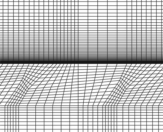
Grids at the central plane of the hole.

Grids of the protected wall.

Grids of the shaped hole. (a) Grids of hole entrance, (b) grids of hole side, (c) grids of hole exit.
Figure 6 shows the effect of grid number on the average temperature of the perforated wall surface. The grid independence tests showed that when the number of model grids is greater than 2 million, the temperature fluctuation is less than 1%, and it can be considered that the grid independence requirement is met. Therefore, in the subsequent calculations, different geometry models adopt a similar grid division method, and the number of whole computational domain grids is about 2 million, where the height of the first layer of the boundary layer is 0.01 mm and the grid spacing ratio is 1:1.1.

Effect of grid number on the average temperature of the perforated wall surface.
It has been proved that the standard k–ε model was good in predicting the trend of film cooling effectiveness and has been successfully used by some other authors [29,30,31]. Therefore, the standard k–ε turbulence model with the standard wall function was finally selected for the calculation. Second-order upwind is selected for discreteness of the flow equation, the turbulent kinetic energy k and the dissipation rate ε. The sub-relaxation is employed to control the computation speed. Convergence is regarded to be achieved when the residual is less than 1 × 10⁶.
3 Results and analysis
3.1 Comparison between cylindrical and shaped holes
3.1.1 Flow field and temperature field downstream of film hole
Figure 7 shows the contours of wall temperature of Model 0 and Model 1, respectively. The temperature contour of the shaped hole (Model 1) is similar to the cylindrical hole (Model 0) in the spanwise direction, but the wall temperature is lowered at the same axial position, that is, the cooling efficiency is increased at the same axial position. At the axial position of x = 80 mm, the wall temperature of Model 1 has dropped below 1,000 K, while the wall temperature of Model 0 is above 1,000 K.

Contours of wall temperature.
Figure 8 shows two positions on the perforated wall surface, marked as line I and line II. The cooling efficiency analysis is performed on the position of these two lines.

Two positions of cooling effectiveness selection.
Figure 9 shows the cooling effectiveness distribution of Model 0 and Model 1 in line I and line II. The cooling effectiveness trend of Model 0 and Model 1 is similar. Line I is the symmetry line of film holes, so the cooling effectiveness increased with fluctuation along line I. The cooling efficiency of Model 1 is always higher than Model 0, at x/L = 80. The cooling efficiency of Model 1 reaches 0.9 and continues to increase, while the cooling effectiveness of Model 0 is lower than 0.9 at any position; the cooling efficiency of Model 1 along line II is still higher than that of Model 0, which means the shaped holes provide a better thermal protection to the wall between two columns of holes.

The cooling effectiveness of Model 0 and Model 1 on line I and line II.
The cross sections in the three different streamwise positions downstream of the third row and the eighth row and the fifteenth row of film hole are selected as shown in Figure 10 and are, respectively, marked as I, II and III cross sections.

Different cross sections of downstream.
Figure 11 shows the temperature distribution and streamline diagram of Model 0 and Model 1 in cross sections I, II and III. The kidney vortices of Model 1 present wider distance in spanwise than that of Model 0 in section I, which offers strong support for expanding the lateral coverage of coolant film. In cross section II, the film of Model 1 has merged together between two adjacent holes in the lateral direction, while that of Model 0 does not. The cooling air film of Model 1 has fully developed in cross section III, forming a lower temperature and more uniform film covering on the wall surface which is benefit for wall cooling. While for Model 0, the kidney vortices are further lifted off the wall surface, causing strong mixing of hot flow and coolant flow. Therefore, the film cooling effect of Model 0 is worse than that of Model 1.

Temperature contours and streamlines in cross sections I, II and III.
3.1.2 Flow inside holes
Figure 12 shows the velocity field inside holes of Model 0 and Model 1. The coolant flow is decelerated in the expansion section of Model 1 causing flow separation, so that the momentum of coolant outflow is reduced, the second flow is closer to the wall surface, and the adhesion property and the ductility of the gas film are improved. The cold flow keeps a high velocity from the inlet to the outlet, so that the momentum of film outflow is high, and the penetration ability to the mainstream is strong, which is not conducive to the formation of a stable film coverage.

Velocity fields inside holes of Model 0 (a) and Model 1 (b).
3.2 Influence of forward expansion angle
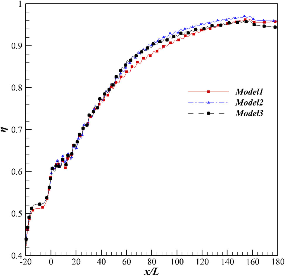
3.2.1 Analysis of cooling effectiveness
Figures 13 and 14 present the cooling effectiveness in line I and line II of film hole, respectively. According to Figures 13 and 14, the trend of cooling effectiveness of the three models is consistent. In addition, the cooling effectiveness of Model 2 is always the highest both in line I and line II after x/L = 60, while Model 3 is basically the same as Model 1.

The cooling effectiveness on line I.
The cooling effectiveness on line II.
3.2.2 Flow field and temperature field downstream of film hole
Figures 15–17 show the temperature field and velocity vector in sections I, II and III, respectively. As shown in Figure 15, the kidney vortex of Model 2 is closer to the wall surface than that of Model 1. This is because the forward expansion angle is increased, which reduces the momentum of the cooling gas outflow, that is, the penetration capacity of coolant flow is reduced. As the expansion angle is further increased, the kidney vortex of Model 3 is as close to the wall surface as Model 2, but the lateral width and the core low-temperature area of the kidney vortex are smaller than Model 2.

Temperature contours and velocity vectors on cross section I (the third row). (a) Model 1, (b) Model 2, (c) Model 3.

Temperature contours and velocity vector on cross section II (the eighth row). (a) Model 1, (b) Model 2, (c) Model 3.

Temperature contours and velocity vector on cross section III (the fifteenth row). (a) Model 1, (b) Model 2, (c) Model 3.
As the cooling air film develops downstream, the cooling air film expanded in both the lateral direction and the height direction, and the kidney vortices merge together in the lateral direction in section II (as shown in Figure 16). In section III, the cooling film of Model 2 is the flattest in spanwise, followed by Model 3 and Model 1. Flat cooling air film demonstrates that the intensity of kidney vortices is rather weak, the vortices are limited beneath the film layer and that is helpful to cool the wall surface.
Figure 18 reports temperature distribution of protected wall in I, II and III sections. The temperature distribution of Model 1, Model 2 and Model 3 in section I is the same, lower near the exit of the hole and increased on both sides of holes. Besides, the temperature of Model 2 is the lowest, while the temperature of Model 1 is the highest. In section II, the lateral temperature distribution of Model 1 is the same as in section I, but the wall temperature between holes of Model 2 and Model 3 significantly decreased, which is almost the same as the temperature downstream of the exit of the hole. This is because two kidney vortices merged together forming a cooling film between adjacent holes in the lateral direction. In section III, the cooling air film is fully developed, and the wall temperature between adjacent holes is further reduced in Model 2 and Model 3, which is about 150 K lower than that in section II.

Temperature along the spanwise direction in different cross sections.
3.2.3 Flow inside holes
Figure 19 shows the velocity field through the center plane of the hole. The coolant flow is accelerated in the inlet section of the hole due to the deflection and convergence of the flow. Then, flow separation takes place in the diffused section of the hole. The low speed zone in Model 1 is smaller, the radial velocity of coolant flow is higher and the velocity in the flow direction is lower, which results in strong penetration into the mainstream. With an increase in forward expansion angle, the area of the low-speed zone in Models 2 and 3 increase in turn and even reverse flow occurs, generating vortices, which greatly reduce the momentum of the coolant jet, making the cooling film attach to the wall better.

Velocity fields through the central plane of the hole. (a) Model 1, (b) Model 2, (c) Model 3.
Figure 20 shows the temperature contours and streamlines at the diffused section of holes. The streamlines show that the vortex scale increases with the forward expansion angle. In Model 3, a large-scale vortex is formed in the expansion section, which causes the coolant flow entrain the main flow into the hole, so the coolant flow and the main flow are premixed inside holes, resulting in an increase in the temperature of the coolant outflow. A similar result was found in the experiments conducted by Kohil and Bogard [32] for a shaped hole with an expansion angle of 15° and an injection angle of 55°. Since this vortex is away from the wall surface of hole, the surrounding coolant flow is lifted by the vortex, which increases the injection angle of coolant jet and weakens the effect of improving the adhesion of the cooling film that results from the increase in the expansion angle.

Temperature contours and streamlines at the diffused section of holes. (a) Model 1, (b) Model 2, (c) Model 3.
Figure 21 shows four cross sections inside the hole, marked as I′, II′, III′ and IV′ and presents maps of streamlines and turbulence kidney energy.

Cross section inside the hole.
Figure 22 presents X vorticity contours and streamlines at different cross sections. The vorticity and velocity distributions of the three models in the undiffused section (section I′) in the hole are basically the same, the left vortex in the hole rotates counterclockwise and the right vortex rotates clockwise. It is worth noting that the vortices of Model 1 interact and substantially completely attenuated in section III′, while the vortices of Model 2 show a trend of asymmetric development and a small vortex generated near the wall (as shown in section III′), which reduces the momentum of the coolant outflow. The vortices scale and intensity of Model 3 in section III′ are larger than that of Model 2, which causes the coolant flow to be lifted off the wall and mixing with the hot flow inside the film hole.

Distribution of eddy and streamlines.
Figure 23 presents the turbulent kinetic energy contours at different sections. The turbulent energy distribution of the three models is similar in the undiffused section. The turbulent energy of Model 1 decays rapidly along sections I′ to IV′, while the turbulent energy of Models 2 and 3 increases in section III′, which is caused by the vortex generated in section III′. However, the vortex scale and strength of Model 3 are so large that the coolant flow entrains the mainstream in the boundary layer.

Turbulence kidney energy contours.
Figure 24 presents the temperature contours of the outlet plane of the hole. The outflow temperature distribution of Model 1 is relatively uniform and that is similar to Model 2, but in the case of Model 3, the temperature of coolant outflow is obviously increased. So the vortex induced in the diffused section can reduce the momentum of coolant outflow on one hand, allow the cooling film to adhere to the wall more easily, on the other hand, the excessive vortex scale causes the coolant flow to entrain the high temperature mainstream and reduce the quality of the cooling gas.

Temperature contours of the outlet plane of the hole. (a) Model 1, (b) Model 2, (c) Model 3.
4 Conclusions
In this study, the flow and the cooling performance of cylindrical and shaped holes were compared by the numerical method, and the effect of the forward expansion angle on the flow field, temperature field and cooling effectiveness downstream of film hole is studied. The main conclusions are as follows:
Compared to cylindrical holes, the diffused structure of shaped holes reduces the radial velocity of coolant jet, increasing the velocity in flow and lateral directions, which enhances the adhesion of the cooling film and strengthens the spreading ability in the lateral direction and results in a better cooling effect.
Within a certain range, as the forward expansion angle increases, the momentum of cooling jets decreases and the forward and lateral coverage of cooling film improved further.
Too large forward expansion angle results in stronger vortex generation in the diffused section away from the hole wall, which increases the injection angle of coolant flow and causes poor film coverage. In addition, the vortex in the mainstream allows the cold air to be mixed with the mainstream, which enhances the convective heat transfer in the hole, increases the cooling outflow temperature and reduces the downstream cooling efficiency of the gas film.
References
[1] Nguyen MN, Fénot M, Lalizel G, Dorignac E. Experimental study of full coverage film cooling optimization. J Phys: Conf Ser. 2012;395:012031.10.1088/1742-6596/395/1/012031Search in Google Scholar
[2] Andrews GE, Alikhanizadeh M, Tehrani FB, Hussain CI. Small diameter film cooling holes: the influence of hole size and pitch. Int J Turbo Jet Engines. 1988;5(1–4):61–72.10.1515/TJJ.1988.5.1-4.61Search in Google Scholar
[3] Andrews GE, Bazdidi-Tehrani F, Hussain CI, Pearson JP. Small Diameter Film Cooling Hole Heat Transfer: The Influence of the Hole Length. International Gas Turbine and Aeroengine Congress and Exposition. American Society of Mechanical Engineers Digital Collection; 1991.10.1115/91-GT-344Search in Google Scholar
[4] Peter B, Dorignac E, Vullierme JJ. Study of the influence of the number of holes rows on the convective heat transfer in the case of full coverage film cooling. Int J Heat Mass Transf. 2003;46:3477–96.10.1016/S0017-9310(03)00126-1Search in Google Scholar
[5] Yang CF, Zhang JZ, Yang WH. Effect of the holes array arrangement on the full coverage film cooling characteristics. J Aerosp Power. 2010;25(7):1524–29.Search in Google Scholar
[6] Yuen CHN, Martinez-Botas RF. Film cooling characteristics of rows of round holes at various streamwise angles in a crossflow: part I. Effectiveness. Int J Heat & Mass Transf. 2003;46(2):237–49.10.1016/j.ijheatmasstransfer.2005.05.019Search in Google Scholar
[7] Bunker RS. A review of shaped hole turbine film-cooling technology. J Heat Transf Trans Asme. 2005;127(4):441–53.10.1115/1.1860562Search in Google Scholar
[8] Goldstein RJ. Film Cooling. Advances in Heat Transfer. vol. 7, New York and London: Academic Press; 1971. p. 321–79.10.1016/S0065-2717(08)70020-0Search in Google Scholar
[9] Crawford ME, Kays WM, Moffat RJ. Full-coverage film cooling-part i: comparison of heat transfer data for three injection angles. ASME J Eng Power. 1980;102:1000–05.10.1115/1.3230334Search in Google Scholar
[10] Yuen CHN, Measurement of local heat transfer coefficient and effectiveness in film cooling geometries”, PhD, University of London, Imperial College of Science, Technology and Medicine, 2000.Search in Google Scholar
[11] Yuen CHN, Martinez-Botas RF, Whitelaw JH. Film cooling effectiveness downstream of compound and fan-shaped holes. ASME 2001-GT-1031; 2001.10.1115/2001-GT-0131Search in Google Scholar
[12] Gritsch M, Schulz A, Wittig S. Adiabatic wall effectiveness measurements of film-cooling holes with expanded exits. ASME J Turbomach. 1998;120:549–56.10.1115/97-GT-164Search in Google Scholar
[13] Thole KA, Gritsch M, Schulz A, Wittig S. Flowfield measurements for film-cooling holes with expanded exits. ASME J Turbomach. 1998;120:327–36.10.1115/96-GT-174Search in Google Scholar
[14] Gritsch M, Schulz A, Wittig S. Film-cooling holes with expanded exits: near hole heat transfer coefficients. Int J Heat Fluid Flow. 2000;21:146–53.10.1016/S0142-727X(99)00076-4Search in Google Scholar
[15] Gritsch M, Saumweber C, Schulz A, Wittig S, Sharp E. Effect of internal coolant crossflow orientation on the discharge coefficient of shaped film-cooling holes. ASME J Turbomach. 2000;122:146–53.10.1115/99-GT-040Search in Google Scholar
[16] Gritsch M, Schulz A, Wittig S. Effect of internal crossflow on the effectiveness of shaped film-cooling holes. ASME J. Turbomach. 2003;125:547–54.10.1115/1.1580523Search in Google Scholar
[17] Dittmar J, Schulz A, Wittig S. Assessment of various film-cooling configurations including shaped and compound angle holes based on large-scale experiments. ASME J Turbomach. 2003;125(1):57–64.10.1115/GT2002-30176Search in Google Scholar
[18] Colban W, Thole K. Influence of hole shape on the performance of a turbine vane endwall film-cooling scheme. Int J Heat Fluid Flow. 2007;28:341–56.10.1016/j.ijheatfluidflow.2006.05.002Search in Google Scholar
[19] Bai JT, Zhu HR, Liu CL. Film cooling characteristic of double-fan shaped film cooling holes[C]ASME Turbo Expo 2009: Power for Land, Sea, & Air. New York, USA: ASME; 2009. p. 185–98.10.1115/GT2009-59318Search in Google Scholar
[20] Bohn D, Moritz N. Influence of hole shaping of staggered multi-hole configurations on cooling film development//Thermophysics Conference. 2000.10.2514/6.2000-2579Search in Google Scholar
[21] Kanani H, Shams M, Ebrahimi R, Ahmadian T. Numerical simulation of film cooling effectiveness on a flat plate. Int J Numer Methods Fluids. 2008;56(8):1329–36.10.1002/fld.1745Search in Google Scholar
[22] Yuen CHN, Martinez-Botas RF. Film cooling characteristics of a single round hole at various streamwise angles in a crossflow: part-I effectiveness. Int J Heat Mass Transf. 2003;46:221–35.10.1016/S0017-9310(02)00274-0Search in Google Scholar
[23] Zhang B, Lin LB, Zhang NR, Xue SS, Ji HH. Experimental investigation of geometrical effect on flow and heat transfer performance of lamilloy cooling structure. Therm Sci. 2020;24(3A):1835–43.10.2298/TSCI190528071ZSearch in Google Scholar
[24] Ammar MK, Oda DA. Design of gravity assist trajectory from earth to jupiter. Appl Mathematics Nonlinear Sci. 2018;3:151–60.10.21042/AMNS.2018.1.00011Search in Google Scholar
[25] Gao W, Zhu L, Guo Y, Wang K. Ontology learning algorithm for similarity measuring and ontology mapping using linear programming. J Intell & Fuzzy Syst. 2017;33:3153–63.10.3233/JIFS-169367Search in Google Scholar
[26] Gao W, Wang W, Tight A. Neighborhood union condition on fractional (G, F, N′, M)-critical deleted graphs. Colloq Mathematicum. 2017;149:291–8.10.4064/cm6959-8-2016Search in Google Scholar
[27] Harraga H, Yebdri M. Attractors for a nonautonomous reaction-diffusion equation with delay. Appl Mathematics Nonlinear Sci. 2018;3:127–50.10.21042/AMNS.2018.1.00010Search in Google Scholar
[28] Pandey PK. A new computational algorithm for the solution of second order initial value problems in ordinary differential equations. Appl Mathematics Nonlinear Sci. 2018;3:167–74.10.21042/AMNS.2018.1.00013Search in Google Scholar
[29] Walters DK, Leylek JH. A Systematic Computational Methodology Applied To A Three-Dimensional Film-Cooling Flowfield, ASME Paper 96-GT-351; 1996.10.1115/96-GT-351Search in Google Scholar
[30] Bc-Ferguson JD, Walters DK, Leylek JH. Performance of Turbulence Models and Near-Wall Treatments in Discrete Jet Film Cooling Simulations, 1998.10.1115/98-GT-438Search in Google Scholar
[31] Daren Z, Xinjun W, Feng Z, Qi, Y. Numerical investigation on the dual effect of upstream steps and transverse trenches on film cooling performance. J Aerosp Eng. July 2019;32(4):04019028.1–04019028.10.10.1061/(ASCE)AS.1943-5525.0001007Search in Google Scholar
[32] Kohil A, Bogard DG. Effects of hole shape on film cooling with large angle injection. Proceedings of the ASME 1999 International Gas Turbine and Aeroengine Congress and Exhibition. Vol. 3: Heat Transfer; Electric Power; Industrial and Cogeneration. Indianapolis, Indiana, USA: ASME; June 7–10, 1999. V003T01A045.Search in Google Scholar
© 2020 Bo Zhang et al., published by De Gruyter
This work is licensed under the Creative Commons Attribution 4.0 International License.
Articles in the same Issue
- Regular Articles
- Model of electric charge distribution in the trap of a close-contact TENG system
- Dynamics of Online Collective Attention as Hawkes Self-exciting Process
- Enhanced Entanglement in Hybrid Cavity Mediated by a Two-way Coupled Quantum Dot
- The nonlinear integro-differential Ito dynamical equation via three modified mathematical methods and its analytical solutions
- Diagnostic model of low visibility events based on C4.5 algorithm
- Electronic temperature characteristics of laser-induced Fe plasma in fruits
- Comparative study of heat transfer enhancement on liquid-vapor separation plate condenser
- Characterization of the effects of a plasma injector driven by AC dielectric barrier discharge on ethylene-air diffusion flame structure
- Impact of double-diffusive convection and motile gyrotactic microorganisms on magnetohydrodynamics bioconvection tangent hyperbolic nanofluid
- Dependence of the crossover zone on the regularization method in the two-flavor Nambu–Jona-Lasinio model
- Novel numerical analysis for nonlinear advection–reaction–diffusion systems
- Heuristic decision of planned shop visit products based on similar reasoning method: From the perspective of organizational quality-specific immune
- Two-dimensional flow field distribution characteristics of flocking drainage pipes in tunnel
- Dynamic triaxial constitutive model for rock subjected to initial stress
- Automatic target recognition method for multitemporal remote sensing image
- Gaussons: optical solitons with log-law nonlinearity by Laplace–Adomian decomposition method
- Adaptive magnetic suspension anti-rolling device based on frequency modulation
- Dynamic response characteristics of 93W alloy with a spherical structure
- The heuristic model of energy propagation in free space, based on the detection of a current induced in a conductor inside a continuously covered conducting enclosure by an external radio frequency source
- Microchannel filter for air purification
- An explicit representation for the axisymmetric solutions of the free Maxwell equations
- Floquet analysis of linear dynamic RLC circuits
- Subpixel matching method for remote sensing image of ground features based on geographic information
- K-band luminosity–density relation at fixed parameters or for different galaxy families
- Effect of forward expansion angle on film cooling characteristics of shaped holes
- Analysis of the overvoltage cooperative control strategy for the small hydropower distribution network
- Stable walking of biped robot based on center of mass trajectory control
- Modeling and simulation of dynamic recrystallization behavior for Q890 steel plate based on plane strain compression tests
- Edge effect of multi-degree-of-freedom oscillatory actuator driven by vector control
- The effect of guide vane type on performance of multistage energy recovery hydraulic turbine (MERHT)
- Development of a generic framework for lumped parameter modeling
- Optimal control for generating excited state expansion in ring potential
- The phase inversion mechanism of the pH-sensitive reversible invert emulsion from w/o to o/w
- 3D bending simulation and mechanical properties of the OLED bending area
- Resonance overvoltage control algorithms in long cable frequency conversion drive based on discrete mathematics
- The measure of irregularities of nanosheets
- The predicted load balancing algorithm based on the dynamic exponential smoothing
- Influence of different seismic motion input modes on the performance of isolated structures with different seismic measures
- A comparative study of cohesive zone models for predicting delamination fracture behaviors of arterial wall
- Analysis on dynamic feature of cross arm light weighting for photovoltaic panel cleaning device in power station based on power correlation
- Some probability effects in the classical context
- Thermosoluted Marangoni convective flow towards a permeable Riga surface
- Simultaneous measurement of ionizing radiation and heart rate using a smartphone camera
- On the relations between some well-known methods and the projective Riccati equations
- Application of energy dissipation and damping structure in the reinforcement of shear wall in concrete engineering
- On-line detection algorithm of ore grade change in grinding grading system
- Testing algorithm for heat transfer performance of nanofluid-filled heat pipe based on neural network
- New optical solitons of conformable resonant nonlinear Schrödinger’s equation
- Numerical investigations of a new singular second-order nonlinear coupled functional Lane–Emden model
- Circularly symmetric algorithm for UWB RF signal receiving channel based on noise cancellation
- CH4 dissociation on the Pd/Cu(111) surface alloy: A DFT study
- On some novel exact solutions to the time fractional (2 + 1) dimensional Konopelchenko–Dubrovsky system arising in physical science
- An optimal system of group-invariant solutions and conserved quantities of a nonlinear fifth-order integrable equation
- Mining reasonable distance of horizontal concave slope based on variable scale chaotic algorithms
- Mathematical models for information classification and recognition of multi-target optical remote sensing images
- Hopkinson rod test results and constitutive description of TRIP780 steel resistance spot welding material
- Computational exploration for radiative flow of Sutterby nanofluid with variable temperature-dependent thermal conductivity and diffusion coefficient
- Analytical solution of one-dimensional Pennes’ bioheat equation
- MHD squeezed Darcy–Forchheimer nanofluid flow between two h–distance apart horizontal plates
- Analysis of irregularity measures of zigzag, rhombic, and honeycomb benzenoid systems
- A clustering algorithm based on nonuniform partition for WSNs
- An extension of Gronwall inequality in the theory of bodies with voids
- Rheological properties of oil–water Pickering emulsion stabilized by Fe3O4 solid nanoparticles
- Review Article
- Sine Topp-Leone-G family of distributions: Theory and applications
- Review of research, development and application of photovoltaic/thermal water systems
- Special Issue on Fundamental Physics of Thermal Transports and Energy Conversions
- Numerical analysis of sulfur dioxide absorption in water droplets
- Special Issue on Transport phenomena and thermal analysis in micro/nano-scale structure surfaces - Part I
- Random pore structure and REV scale flow analysis of engine particulate filter based on LBM
- Prediction of capillary suction in porous media based on micro-CT technology and B–C model
- Energy equilibrium analysis in the effervescent atomization
- Experimental investigation on steam/nitrogen condensation characteristics inside horizontal enhanced condensation channels
- Experimental analysis and ANN prediction on performances of finned oval-tube heat exchanger under different air inlet angles with limited experimental data
- Investigation on thermal-hydraulic performance prediction of a new parallel-flow shell and tube heat exchanger with different surrogate models
- Comparative study of the thermal performance of four different parallel flow shell and tube heat exchangers with different performance indicators
- Optimization of SCR inflow uniformity based on CFD simulation
- Kinetics and thermodynamics of SO2 adsorption on metal-loaded multiwalled carbon nanotubes
- Effect of the inner-surface baffles on the tangential acoustic mode in the cylindrical combustor
- Special Issue on Future challenges of advanced computational modeling on nonlinear physical phenomena - Part I
- Conserved vectors with conformable derivative for certain systems of partial differential equations with physical applications
- Some new extensions for fractional integral operator having exponential in the kernel and their applications in physical systems
- Exact optical solitons of the perturbed nonlinear Schrödinger–Hirota equation with Kerr law nonlinearity in nonlinear fiber optics
- Analytical mathematical schemes: Circular rod grounded via transverse Poisson’s effect and extensive wave propagation on the surface of water
- Closed-form wave structures of the space-time fractional Hirota–Satsuma coupled KdV equation with nonlinear physical phenomena
- Some misinterpretations and lack of understanding in differential operators with no singular kernels
- Stable solutions to the nonlinear RLC transmission line equation and the Sinh–Poisson equation arising in mathematical physics
- Calculation of focal values for first-order non-autonomous equation with algebraic and trigonometric coefficients
- Influence of interfacial electrokinetic on MHD radiative nanofluid flow in a permeable microchannel with Brownian motion and thermophoresis effects
- Standard routine techniques of modeling of tick-borne encephalitis
- Fractional residual power series method for the analytical and approximate studies of fractional physical phenomena
- Exact solutions of space–time fractional KdV–MKdV equation and Konopelchenko–Dubrovsky equation
- Approximate analytical fractional view of convection–diffusion equations
- Heat and mass transport investigation in radiative and chemically reacting fluid over a differentially heated surface and internal heating
- On solitary wave solutions of a peptide group system with higher order saturable nonlinearity
- Extension of optimal homotopy asymptotic method with use of Daftardar–Jeffery polynomials to Hirota–Satsuma coupled system of Korteweg–de Vries equations
- Unsteady nano-bioconvective channel flow with effect of nth order chemical reaction
- On the flow of MHD generalized maxwell fluid via porous rectangular duct
- Study on the applications of two analytical methods for the construction of traveling wave solutions of the modified equal width equation
- Numerical solution of two-term time-fractional PDE models arising in mathematical physics using local meshless method
- A powerful numerical technique for treating twelfth-order boundary value problems
- Fundamental solutions for the long–short-wave interaction system
- Role of fractal-fractional operators in modeling of rubella epidemic with optimized orders
- Exact solutions of the Laplace fractional boundary value problems via natural decomposition method
- Special Issue on 19th International Symposium on Electromagnetic Fields in Mechatronics, Electrical and Electronic Engineering
- Joint use of eddy current imaging and fuzzy similarities to assess the integrity of steel plates
- Uncertainty quantification in the design of wireless power transfer systems
- Influence of unequal stator tooth width on the performance of outer-rotor permanent magnet machines
- New elements within finite element modeling of magnetostriction phenomenon in BLDC motor
- Evaluation of localized heat transfer coefficient for induction heating apparatus by thermal fluid analysis based on the HSMAC method
- Experimental set up for magnetomechanical measurements with a closed flux path sample
- Influence of the earth connections of the PWM drive on the voltage constraints endured by the motor insulation
- High temperature machine: Characterization of materials for the electrical insulation
- Architecture choices for high-temperature synchronous machines
- Analytical study of air-gap surface force – application to electrical machines
- High-power density induction machines with increased windings temperature
- Influence of modern magnetic and insulation materials on dimensions and losses of large induction machines
- New emotional model environment for navigation in a virtual reality
- Performance comparison of axial-flux switched reluctance machines with non-oriented and grain-oriented electrical steel rotors
- Erratum
- Erratum to “Conserved vectors with conformable derivative for certain systems of partial differential equations with physical applications”