
Experimental investigation on the three-dimensional flow field from a meltblowing slot die
-
Changchun Ji


Abstract
To investigate the distribution characteristics of the three-dimensional flow field under the slot die, an online measurement of the airflow velocity was performed using a hot wire anemometer. The experimental results show that the air-slot end faces have a great influence on the airflow distribution in its vicinity. Compared with the air velocity in the center area, the velocity below the slot end face is much lower. The distribution characteristics of the three-dimensional flow field under the slot die would cause the fibers at different positions to bear inconsistent air force. The air velocity of the spinning centerline is higher than that around it, which is more conducive to fiber diameter attenuation. The violent fluctuation of the instantaneous velocity of the airflow could easily cause the meltblowing fiber to whip in the area close to the die.
1 Introduction
Meltblowing technology is a one-step process for producing ultrafine fibers. Meltblowing fibers mainly use polypropylene chips as the main raw material, and their diameters are generally distributed between 1 and 5 µm (1). The meltblowing fibers have the characteristics of small diameter and large specific surface area, and the resulting products could be used as air filter materials, insulation materials, medical mask materials, thermal insulation materials, and wiping cloth for precision instruments (2,3). Especially since December 2019, because of the outbreak of COVID-19, the meltblowing materials and the meltblowing technology have attracted greater attention.
In the meltblowing production process, the slot die shown in Figure 1 is one of the most common air draft devices, and it is the core component of the entire equipment. As shown in Figure 1, the two high-speed and high-temperature jets are ejected from the air holes of the slot die, and they draw the polymer melt into ultrafine fibers (4). The flow field under the slot die not only affects the diameter of the meltblowing fiber but also determines the strength of the fiber. The airflow field below the slot die is the key to studying the fiber drawing mechanism. Therefore, many studies have carried out works on the airflow field distribution characteristics under the meltblowing slot die.
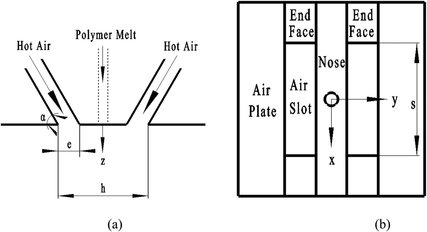
A common slot die: (a) section view; (b) view of die surface.
Shambaugh and his team measured the isothermal airflow field under the common slot die (5). Through the statistical analysis of the experimental data, they obtained the empirical equation of the velocity distribution. Harpham and Shambaugh (6) added an air heating and heat preservation device to the slot-shaped die, so as to realize the measurement of the non-isothermal flow field in the melt-blown process. The temperature field of the slot die was measured by a thermocouple and they obtained the empirical equations for the temperature distribution. Tate and Shambaugh (7) measured the velocity distribution of the airflow field and adapted the die used in the experiment of Harpham and Shambaugh (5,6). By comparing the flow field experimental data of several different geometric parameter combinations, the meltblowing die head with the retracted nose had a higher flow field velocity than that with the protruding head end. Chen et al. (8) and Wang and Ke (9) used a hot-wire anemometer and a laser Doppler anemometer to measure the flow field of the slot die with multiple geometric parameters. They found that when the width of the air slot was larger, the air velocity and the air temperature in the direction of the flow field axis were greater. Xie and Zeng (10) used a hot-wire anemometer to measure the high-speed flow field under the slot die online and investigated the relationship between fiber movement and airflow velocity. Xie et al. (11) detected and analyzed the turbulent flow field under the slot die with a single spinneret hole. Xie et al. (12) used particle image velocimetry technology to explore the instantaneous velocity distribution in the airflow field and experimentally proved the existence of the triangular recirculation zone. To increase the drafting force of the airflow, Shambaugh et al. (13) added a pair of Louvers below the common slot die, and they used a pitot tube to perform the online measurement of the air velocity. Wang et al. designed a new slot die with a flow-stabilizing part, and the results showed that the drafting speed and air temperature in the flow field increased, which was conducive to the preparation of smaller meltblowing fibers (14,15,16).
In recent years, with the development of computational fluid dynamics (CFD) technology, many researchers have performed numerical analysis on the airflow field under the slot die (17,18,19,20). Compared with the CFD method, the data collected by the experimental instruments are more convincing. On one hand, in the past, many researchers only investigated the flow field distribution of a few planes during the online measurement (7,8,9,10,11,12,13). Because of the few collection points, the research results could not reflect all the characteristics of the entire flow field. On the other hand, in the researches, the flow field under the slot die is regarded as a two-dimensional flow field distribution, and the influence of the air-slot end face on the flow field distribution has not been investigated. In this article, we used the experimental equipment to measure the three-dimensional airflow field under the slot die online, and the relationship between flow field distribution and fiber drafting was also discussed.
2 Experimental device and procedures
2.1 Experiment layout
The device used in this flow field measurement experiment was mainly composed of a common die head, a hot wire anemometer, a stepping motor, and a three-dimensional traverse movement equipment. Figure 2 shows the experimental design diagram of the flow field below a common slot die. The air source of the meltblowing die head was provided by an air compressor and its temperature was 310 K. After being filtered, the high-pressure gas was controlled by a two-stage valve to be more stably delivered into the gas chamber of the die. In the experimental design (Figure 2), the pressure value of the compressed air was 0.05 MPa. The air flow was then ejected from the slot-jet holes of the die and then it formed a high-speed flow field under the die. The hot wire anemometer was used for online data collection in the high-speed flow field.
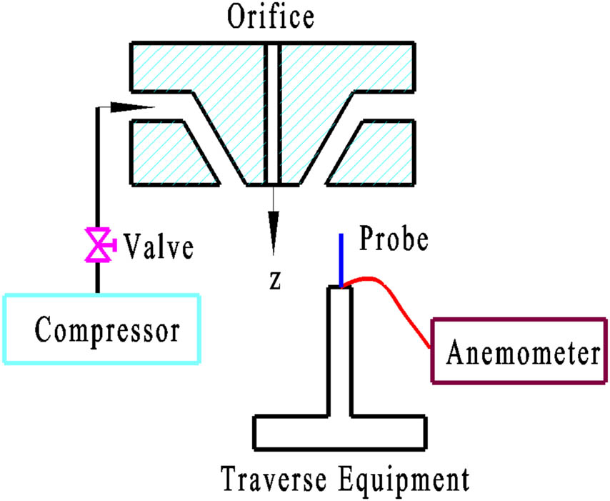
The experiment system.
2.2 Slot die
Figure 1 is a schematic diagram of a meltblowing die with double air slots. The slot width e of the jet hole, the inclination angle α of the jet hole, the distance h of the outer ends of the air-slot holes, and the lengths of the air-slot hole referred to the research of Shambaugh and Xie (5,6,11,12).
The jet inclination angle α of the slot die was 60°, which was the same as that used in industrial production. To facilitate the processing of the die and the convenience of experimental measurement, the size of the melt blown die was enlarged. The slot width e of the air jet hole and the distance h were twice that of the Shambaugh’s die head (5,6), which were 1.3 and 6.64 mm, respectively. The slot length s of the jet hole of the meltblowing die was 12 mm, which was the same as the length of the jet hole of the slot die on the HDF-6D meltblowing machine (11,12).
2.3 Hot wire anemometer
In this work, the hot-wire anemometer used was produced by Dantec Company, and its model was CTA/HWA (Streamline). It mainly included a host (Dantec StreamLine Frame 90N10), a calibrator (Dantec Calibration System 90H10), temperature measurement Module (Dantec StreamLine CTA 90C20), and speed measurement module (Dantec StreamLine CTA90C10). The hot wire anemometer, A/D board, and other corresponding analysis software constitute a complete measurement and analysis system. Among them, the maximum conversion frequency of the A/D board was 500 kHz, and the resolution was 16 bits, which met the requirements of flow field signal acquisition in this experiment. The miniature hot wire probe used with the hot wire anemometer was a one-dimensional probe, and its model was Dantec Dynamic 55P11. The probe wire had a length of 1.2 mm and a diameter of 5 µm. It was made of platinum tungsten wire and could withstand a certain impact load. The sensitivity of the probe was high, the resolution could reach 0.01 m/s, the minimum measurable air velocity range was 0.05 m/s, and the maximum could reach more than 300 m/s, which could meet the experimental requirements of the flow field.
2.4 Three-dimensional traverse equipment
An AKS-01Z stepper motor was installed on the three-dimensional traverse equipment. The base of the three-dimensional traverse equipment was made of cast iron and had good stability. The rotation of the screw driven by the stepper motor could realize the directional movement of the one-dimensional probe. The movement accuracies in three different directions along the x-, y-, and z-axes were all 0.01 mm. Therefore, the three-dimensional traverse device could accurately move the one-dimensional probe. It was positioned on each measuring point in the flow field under the die head ground and smoothly. In the experiment, the stepper motor was used to control the micro-scale flow displacement of the one-dimensional probe of the hot wire anemometer, and the displacement of the one-dimensional probe was set on the AKS-01Z stepper motor controller. Every time the controller sent 80 pulses, the displacement of the one-dimensional probe was 2 mm. The acquisition time of the measurement points in the flow field below the meltblowing die was set in the program of the AKS-01Z stepper motor controller. The steady-state flow field of the meltblowing die head could be obtained by taking the average of the instantaneous speed. The collection time of the hot wire anemometer to the measurement point was set in the program of the stepping motor. The acquisition time of each measurement point in the field was 30 s. When the stepper motor drove the one-dimensional probe of the hot wire anemometer to move to the next measurement point, the stepper motor had just stopped and the one-dimensional probe was in a state of vibration because of inertia. Therefore, the one-dimensional probe started to collect data in the flow field after 10 s, so as to ensure that the one-dimensional probe was stationary for a sufficient time and the collected signal data were correct.
2.5 Measuring area and measuring points
The coordinate system used in this experiment is shown in Figures 1 and 2, and the origin was at the center of the slot die. The x-axis was parallel to the two air slots and coincided with the centerline of the nose; the y-axis was perpendicular to the x-axis and they intersected the origin; and the z-axis was collinear with the axis of the orifice. Because the three-dimensional airflow field under the meltblowing die was symmetrical about the plane xz and the plane yz, only a quarter of the entire flow field needed to be measured, which could greatly reduce the workload and test time. The measurement area was within the range of 5 mm ≤ z ≤ 103 mm, 0 mm ≤ x ≤ 4.5 mm, and 0 cm ≤ y ≤ 3 cm. The z direction could not be set to 0 mm; the reason was that the gas jet velocity in the flow field was very large in the area near the die head, and the wire diameter of the hot wire anemometer probe was very small. Therefore, when the wire of the hot wire anemometer was close to the die, the one-dimensional probe was often broken and the experiment was interrupted.
The distribution of the measured data points could be seen in Figure 3. According to the flow field distribution characteristics under the slot die, the measurement points along the y-axis direction near the center line of the flow field should be dense; the measurement points in the area farther from the flow field spinning line could be appropriately sparser. It effectively reduced the measurement data and experimental test time, and the one-dimensional probe of the hot wire anemometer could obtain the flow field data more comprehensively. In this experiment, the displacement distance of the acquisition points in the direction parallel to the z-axis was 2 mm, and the total number of single lines was 50. In the direction parallel to the y-axis, the distance between the measurement points was not equal, and there were 19 data points in each line. The interval in the range of 0–10 cm was 0.1 cm, and the interval in the remaining area was 0.25 cm. There were four measuring points parallel to the x direction, namely 0, 1.5, 3, and 4.5 mm.
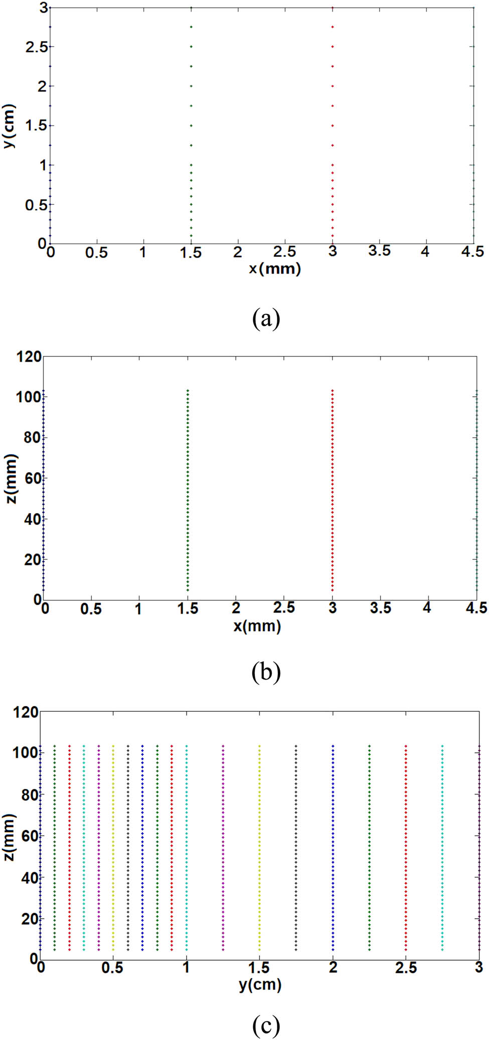
Distribution of measuring points: (a) the projection on the xy plane; (b) the projection on the xz plane; (c) the projection on the yz plane.
3 Experimental results and discussion
3.1 Velocity distribution of three-dimensional flow field
To investigate the mean velocity distribution characteristics of the three-dimensional flow field below the slot die, some planes that are called z-planes and parallel to the xy plane are selected, and the distribution of velocities on these planes is shown in Figure 4. These planes are located at different positions and are assigned different z values. These half peaks are the maximum values of the air velocities on the different z-planes. In any of the z-planes in Figure 4a–f, the velocity of the airflow gradually reduces along the y-axis. In the area close to the slot die, the gas velocity on the y-axis in each z plane changes drastically within the range of 0 cm ≤ y ≤ 1 cm, whereas in other ranges, the gas velocity basically changes gently along the y-axis. Therefore, there are more measurement points in the range of 0–1 mm and fewer measurement points in the range of 1–3 mm. It shows that the measurement scheme of this experiment is reasonable. Through comparison, it could be found that when the z value increases, the half-peak on the z-plane gradually becomes flat. In addition, it could be seen from Figure 4a–f that the air velocity in the range of 1–2 mm along the y-axis direction on the z plane gradually increases as it moves away from the die. This means that as the distance to the die increases, the maximum jet velocity at the center of the z planes decreases, and the high-speed jet continues to spread to the surrounding.
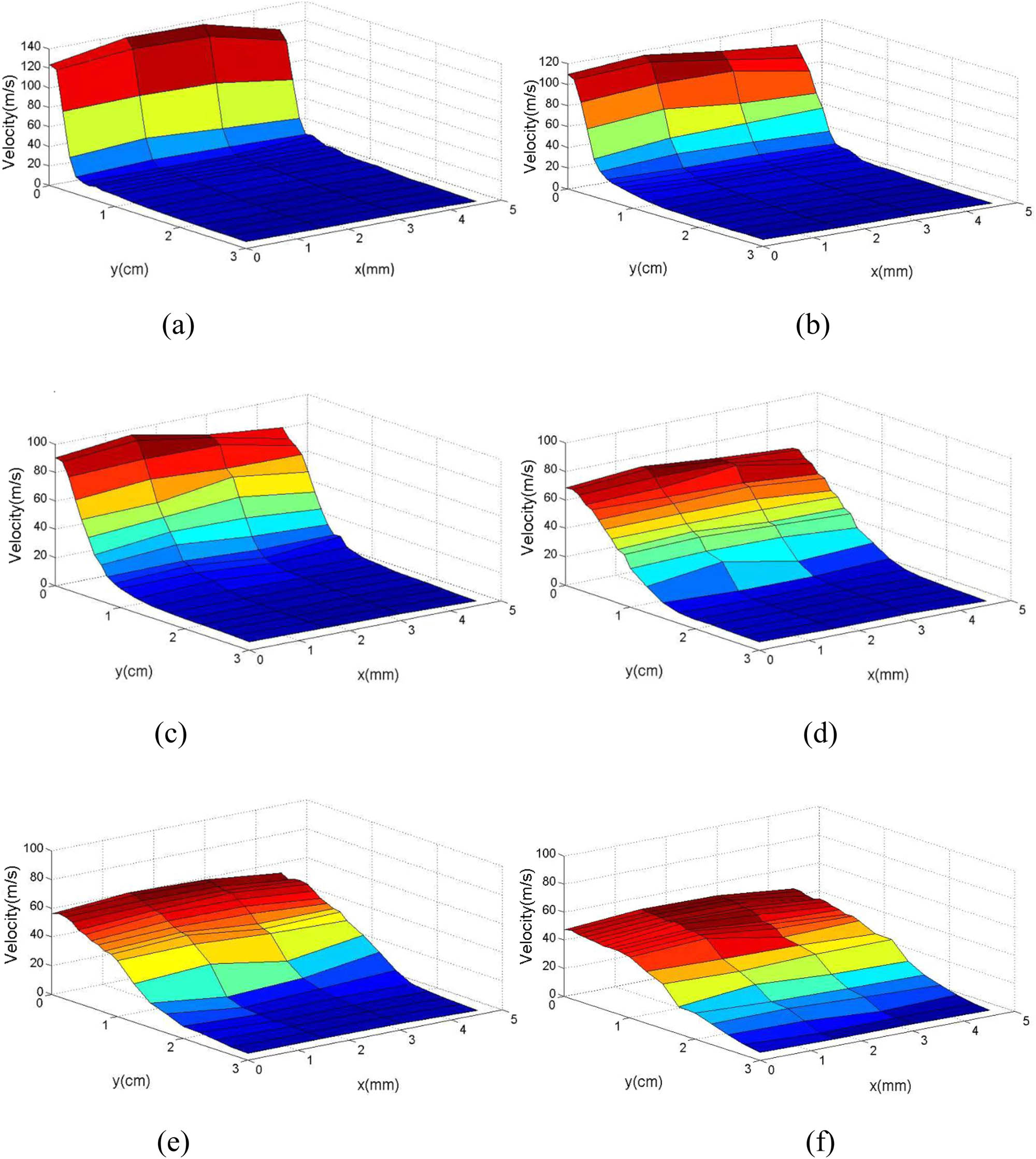
Velocity distribution on different z planes. (a) z = 9 mm, (b) z = 19 mm, (c) z = 29 mm, (d) z = 49 mm, (e) z = 69 mm, (f) z = 95 mm.
Figure 4a–f shows that the airflow velocities of each z-plane in the range of 0, 1.5, and 3 mm in the x direction have little difference. When x = 4.5 mm, the air velocity on each z plane is lower than that at other corresponding positions. Therefore, in the three-dimensional air flow field below the slot die, the difference between the velocity at the center of the flow field and the one nearby is small, whereas in the area far from the center, the air velocity decreases sharply. This shows that the slot end face of air jet has a greater influence on the flow field distribution below it and in the adjacent area. The airflow force experienced by the meltblowing fiber is proportional to the square of the difference between the air velocity and the fiber velocity (21). Because of the large velocity difference between the center area and the area near the slot end face, the stretching forces of the polymer melt at the two places are also different. It could be inferred that the fineness and strength of meltblowing fibers vary with the position of the spinneret holes. Therefore, to ensure the uniformity of the diameter and quality of the melt-blown fiber, the spinneret should be placed in an area away from the slot end surface of the jet hole.
3.2 Average velocity distribution on the yz plane of the flow field
Figure 4 shows that the slot end face of the jet hole has a greater influence on the flow field distribution in the nearby area, whereas the air velocity in the area far away from the end face of the slot hole has a small effect. Because the length of the meltblowing die used in the factory along the x-axis direction is even greater than 1 m, the jet flow field below the meltblowing die still has two-dimensional flow field distribution characteristics in most areas. Therefore, for the slot die, the flow field distribution on the yz plane has certain representative significance. In this section, we focus on the experimental measurement data in the symmetrical center plane of the die flow field (i.e., the yz plane) and it has guiding significance for the industrial production of meltblowing fibers.
Figure 5 shows the air velocity distribution at different z-lines of the center plane of the flow field. It could be seen from Figure 5a that when z = 5 mm, there is a complete peak in the air velocity of the y direction, indicating that the two jets have not yet merged and the jets still maintain their own characteristics. Through CFD calculation and numerical analysis, Krutka and Shambaugh (17) divided the entire flow field of the double-slot meltblowing die into three areas: “two independent jets’ zone,” “jet fusion zone,” and “single jet zone.” Among them, the air velocity in the “two independent jets’ zone” and the “jet fusion zone” is very high, and they are very close to the die, which could easily damage the probe wire and is difficult to measure. However, in this experiment, the flow field data of two independent jets under the common slot die were captured. When z = 7 mm, there is only one half peak on the velocity profile of the airflow, and the two jets have merged into one jet inthe flow field of the die. From Figure 5b, it could be concluded that, consistent with the previous Figure 4a–f, as the value of z increases, the maximum jet velocity of the y-axis direction in the yz plane also decreases. On the contrary, the air velocity in the area far away from the z-axis gradually increases. The difference of the maximum velocity peaks between the straight line z = 25 mm and the straight line z = 85 mm is as much as 50 m/s, indicating that the high-speed jet in the center plane of the slot die attenuates faster, and the high-speed area of the airflow is close to the die head. Therefore, the online measurement experiment of meltblowing fiber shows that the attenuation of fiber diameter mainly occurs in the range of 1.5 cm below the die (22).
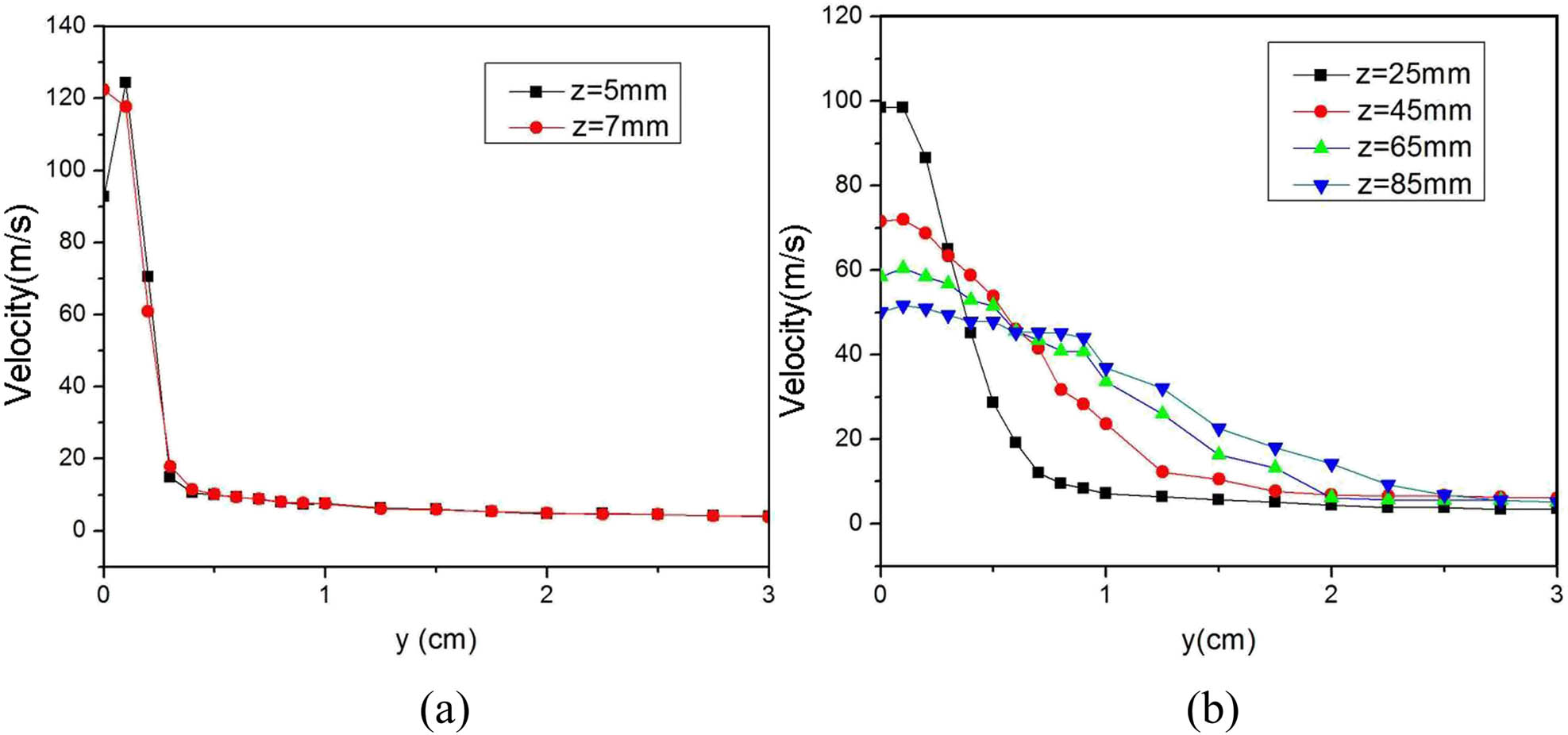
Velocity distribution on different z-lines: (a) the area near the die; (b) the middle area and the area away from the die.
Figure 6 shows the velocity changes at different y-lines of the yz plane in the flow field below the slot die. The air velocity on the z-axis (i.e., line y = 0 cm) decreases with the increase in the z value; with the increase in the distance from the die head, the gas velocities on the line y = 0.3 cm, line y = 0.5 cm, and straight line y = 1.0 cm raise, whereas the airflow velocity at the boundary (i.e., line y = 3 cm) has almost no gradient. This is because the fused jet spreads and drives the airflow around the surrounding area, and the airflow around the axis further affects the movement of the gas farther away. The straight line y = 3 cm is far from the center line of the flow field, and the surrounding air is less affected by the high-speed jet.
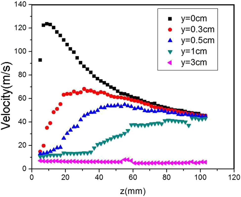
Velocity distribution on different y-lines.
By comparing the speed on the straight line y = 0 cm with the other four lines (i.e., line y = 0.3 cm, line y = 0.5 cm, line y = 1.0 cm, and line y = 3.0 cm), it could be seen that within the range of 0 mm ≤ z ≤ 40 mm, the velocity on the spinning line in the center plane of the flow field is very different from the air velocity around and far away, the difference is even up to 110 m/s. From the measured speed data in Figure 6, it could be seen that in the range of 0 cm ≤ z ≤ 1.5 cm, the high-speed area in the center plane of the flow field is concentrated at and near the spinning centerline.
We used the high-speed camera equipment to photograph the fiber drafting process under the common slot die. The high-speed camera was produced by American Redlake Company and the exposure frequency was 5,000 fps in the experiment. Figure 7 shows the fiber trajectory captured by the Redlake high-speed camera. In Figure 6, it could be found that the velocities on different y-lines in the area close to the common slot die are very different. Therefore, in the production process of the meltblowing fiber (Figure 7), the fiber in this area is prone to whip and is far away from the spinning line, which is unfavorable for fiber thinning.

Motion trajectory of a meltblowing fiber.
3.3 Instantaneous velocity in the airflow field of the meltblowing die
During the drafting process of meltblowing fiber, the fiber mainly moves along the centerline of the flow field. The instantaneous speed change on the spinning centerline (i.e., the z-axis) is extremely important for the refinement and movement of the fiber. We examined the instantaneous speed on the spinning centerline. It could be seen from Figure 8 that the velocities of these two points on the centerline of the flow field below the meltblowing die change drastically. The instantaneous speed at each point changes up and down around a certain average speed. For example, at the positions 0 mm, 0 cm, and 5 mm, basically all speeds fluctuate around 90 m/s. This is because that the airflow under the meltblowing die is in a turbulent flow state, and various physical parameters such as air velocity, pressure, and temperature in the flow field change randomly with time and space. The experimental measurement data shown in Figure 8 verify that the speed on the spinning line under the flow field of the meltblowing die is constantly changing at all times, and the turbulent flow is complex and changeable. As a result, it would affect the stability of the meltblowing fiber drafting, could easily cause the fiber to leave the spinning line, and would aggravate the whip around the spinning line (Figure 7). In addition, it would cause uneven diameter of the fibers produced and the adhesion of adjacent fibers, which would affect the appearance quality of the nonwoven products.
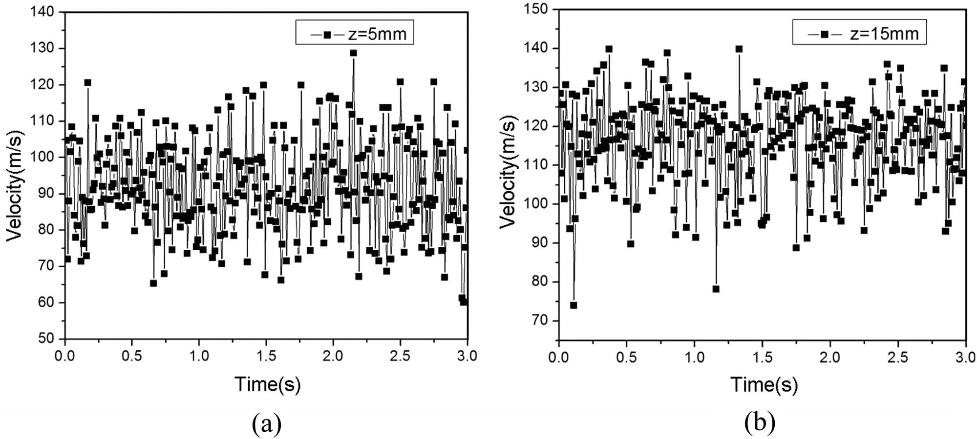
Instantaneous velocity on the center line of the flow field: (a) position (0 mm, 0 cm, and 5 mm); (b) position (0 mm, 0 cm, and 15 mm).
4 Conclusions
In this article, with the help of the hot wire anemometer, the three-dimensional traverse equipment, and the stepper motor, the three-dimensional jet flow field under the common slot die was measured online, and the instantaneous velocity and average velocity in the flow field were obtained. At the same time, the data of the experiment were processed and analyzed.
In the area close to the slot end face, the airflow velocity is significantly reduced, and the velocity difference with the central area is large. Therefore, the slot end face has a great influence on the flow field distribution below it or in the adjacent area. The characteristics of the three-dimensional flow field distribution of the slot die determine that the fibers in the area near the slot end face and the center area receive different air draft forces. It would lead to inconsistencies in the diameter and strength of the fiber produced by the slot die.
In the three-dimensional flow field below the slot die, the air velocities in the center area and its vicinity are high, and there is little difference between them. Because the air-slot length of the meltblowing die used in industrial production is more than 1 m, most of the three-dimensional flow field areas below it still have two-dimensional flow field distribution characteristics.
On the center plane of the three-dimensional flow field below the slot die, the air velocity of the spinning thread and its surroundings is relatively high. In the area far away from the spinning line, the air velocity is low, and there is no drafting effect on the fiber. Because of jet diffusion and energy exchange, as the distance to the die increases, the air velocity on the spinning line decreases sharply. In addition, the instantaneous speed on the spinning line fluctuates rapidly around the average speed. It could easily cause the fiber to whip, which is not good for the smooth drafting of the fiber.
Acknowledgments
This work was financially supported by the Introduction of PhD Program in Natural Science (ZB-2018006), the Provincial Key Laboratory of Soochow University (KJS1836), the Scientific and Technological Innovation Programs of Higher Education Institution in Shanxi (No. 2019L0992), and the National Natural Science Foundation of China (Grant No. 51765063 and 51703124).
Conflict of interest: The authors declare that there are no conflicts of interest regarding the publication of this article.
References
(1) Han W, Bhat GS, Wang X. Investigation of nanofiber breakup in the melt-blowing process. Ind Eng Chem Res. 2016;55:3150–6.10.1021/acs.iecr.5b04472Search in Google Scholar
(2) Wang ZF, Bates FS, Kumar S, Macosko CW. Water droplet spreading and imbibition on superhydrophilic poly(butylene terephthalate) melt-blown fiber mats. Chem Eng Sci. 2016;146:104–14.10.1016/j.ces.2016.02.006Search in Google Scholar
(3) Wang ZF, Macosko CW, Bates FS. Fluorine-enriched melt-blown fibers from polymer blends of poly(butylene terephthalate) and a fluorinated multiblock copolyester. ACS Appl Mater Interfaces. 2016;8:3006–12.10.1021/acsami.5b09976Search in Google Scholar PubMed
(4) Hao X, Zeng Y. A review on the studies of air flow field and fiber formation process during melt blowing. Ind Eng Chem Res. 2019;58:11624–37.10.1021/acs.iecr.9b01694Search in Google Scholar
(5) Harpham AS, Shambaugh RL. Flow field of practical dual rectangular jets. Ind Eng Chem Res. 1996;35:3776–81.10.1021/ie960074cSearch in Google Scholar
(6) Harpham AS, Shambaugh RL. Velocity and temperature fields of dual rectangular jets. Ind Eng Chem Res. 1997;36:3937–43.10.1021/ie970145nSearch in Google Scholar
(7) Tate BD, Shambaugh RL. Temperature fields below melt-blowing dies of various geometries. Ind Eng Chem Res. 2004;43:5405–10.10.1021/ie040066tSearch in Google Scholar
(8) Chen T, Wang X, Huang X. Modeling the air-jet flow field of a dual slot die in the melt-blowing nonwoven process. Text Res J. 2004;74:1018–24.10.1177/004051750407401114Search in Google Scholar
(9) Wang X, Ke Q. Empirical formulas for distributions of air velocity and temperature along the spinline of a dual slot die. Poly Eng Sci. 2005;45:1092–7.10.1002/pen.20374Search in Google Scholar
(10) Xie S, Zeng Y. Turbulent air flow field and fiber whipping motion in the melt blowing process: Experimental study. Ind Eng Chem Res. 2012;51:5346–52.10.1021/ie202938bSearch in Google Scholar
(11) Xie S, Han W, Jiang G, Chen C. Turbulent air flow field in slot-die melt blowing for manufacturing microfibrous nonwoven materials. J Mater Sci. 2018;53:6991–7003.10.1007/s10853-018-2008-ySearch in Google Scholar
(12) Xie S, Jiang G, Ye B, Shentu B. Particle image velocimetry (PIV) investigation of the turbulent airflow in slot-die melt blowing. Polymers. 2020;12:279–91.10.3390/polym12020279Search in Google Scholar PubMed PubMed Central
(13) Shambaugh RL, Krutty JD, Singleton SM. Melt blowing dies with louvers. Ind Eng Chem Res. 2015;54:12999–3004.10.1021/acs.iecr.5b03400Search in Google Scholar
(14) Wang Y, Wang X. Numerical analysis of new modified melt-blowing dies for dual rectangular jets. Polym Eng Sci. 2014;54:110–6.10.1002/pen.23536Search in Google Scholar
(15) Wang Y, Ji C, Zhou J. Experimental and numerical analysis of an improved melt-blowing slot-die. e-Polymers. 2019;19:612–21.10.1515/epoly-2019-0065Search in Google Scholar
(16) Wang Y, Zhou J, Gao X. Numerical analysis of airflow fields from new melt-blowing dies for dual-slot jets. ACS Omega. 2020;5:13409–15.10.1021/acsomega.0c01668Search in Google Scholar PubMed PubMed Central
(17) Krutka HM, Shambaugh RL. Analysis of a melt-blowing die: Comparison of CFD and experiments. Ind Eng Chem Res. 2002;41:5125–38.10.1021/ie020366fSearch in Google Scholar
(18) Xin S, Wang X. Investigation into the effect of the angle of dual slots on an air flow field in melt blowing via numerical simulation. e-Polymers. 2016;16:337–42.10.1515/epoly-2016-0057Search in Google Scholar
(19) Wang Y, Zhou J. Effect of slot end faces on the three-dimensional airflow field from the melt-blowing die. J Polym Eng. 2020;40:607–13.10.1515/polyeng-2020-0049Search in Google Scholar
(20) Ji C, Wang Y, Sun Y. Numerical investigation on a melt-blowing die with internal stabilizers. J Ind Text 2019. 10.1177/1528083719866935.Search in Google Scholar
(21) Shambaugh BR, Papavassiliou DV, Shambaugh RL. Next generation modeling of melt blowing. Ind Eng Chem Res. 2011;50:12233–45.10.1021/ie200836aSearch in Google Scholar
(22) Bansal V, Shambaugh RL. On-line determination of diameter and temperature during melt blowing of polypropylene. Ind Eng Chem Res. 1998;37:1799–806.10.1021/ie9709042Search in Google Scholar
© 2020 Changchun Ji and Yudong Wang, published by De Gruyter
This work is licensed under the Creative Commons Attribution 4.0 International License.
Articles in the same Issue
- Regular Articles
- The regulatory effects of the number of VP(N-vinylpyrrolidone) function groups on macrostructure and photochromic properties of polyoxometalates/copolymer hybrid films
- How the hindered amines affect the microstructure and mechanical properties of nitrile-butadiene rubber composites
- Novel benzimidazole-based conjugated polyelectrolytes: synthesis, solution photophysics and fluorescent sensing of metal ions
- Study on the variation of rock pore structure after polymer gel flooding
- Investigation on compatibility of PLA/PBAT blends modified by epoxy-terminated branched polymers through chemical micro-crosslinking
- Investigation on degradation mechanism of polymer blockages in unconsolidated sandstone reservoirs
- Investigation on the effect of active-polymers with different functional groups for EOR
- Fabrication and characterization of hexadecyl acrylate cross-linked phase change microspheres
- Surface-induced phase transitions in thin films of dendrimer block copolymers
- ZnO-assisted coating of tetracalcium phosphate/ gelatin on the polyethylene terephthalate woven nets by atomic layer deposition
- Animal fat and glycerol bioconversion to polyhydroxyalkanoate by produced water bacteria
- Effect of microstructure on the properties of polystyrene microporous foaming material
- Synthesis of amphiphilic poly(ethylene glycol)-block-poly(methyl methacrylate) containing trityl ether acid cleavable junction group and its self-assembly into ordered nanoporous thin films
- On-demand optimize design of sound-absorbing porous material based on multi-population genetic algorithm
- Enhancement of mechanical, thermal and water uptake performance of TPU/jute fiber green composites via chemical treatments on fiber surface
- Enhancement of mechanical properties of natural rubber–clay nanocomposites through incorporation of silanated organoclay into natural rubber latex
- Preparation and characterization of corn starch/PVA/glycerol composite films incorporated with ε-polylysine as a novel antimicrobial packaging material
- Preparation of novel amphoteric polyacrylamide and its synergistic retention with cationic polymers
- Effect of montmorillonite on PEBAX® 1074-based mixed matrix membranes to be used in humidifiers in proton exchange membrane fuel cells
- Insight on the effect of a piperonylic acid derivative on the crystallization process, melting behavior, thermal stability, optical and mechanical properties of poly(l-lactic acid)
- Lipase-catalyzed synthesis and post-polymerization modification of new fully bio-based poly(hexamethylene γ-ketopimelate) and poly(hexamethylene γ-ketopimelate-co-hexamethylene adipate) copolyesters
- Dielectric, mechanical and thermal properties of all-organic PI/PSF composite films by in situ polymerization
- Morphological transition of amphiphilic block copolymer/PEGylated phospholipid complexes induced by the dynamic subtle balance interactions in the self-assembled aggregates
- Silica/polymer core–shell particles prepared via soap-free emulsion polymerization
- Antibacterial epoxy composites with addition of natural Artemisia annua waste
- Design and preparation of 3D printing intelligent poly N,N-dimethylacrylamide hydrogel actuators
- Multilayer-structured fibrous membrane with directional moisture transportability and thermal radiation for high-performance air filtration
- Reaction characteristics of polymer expansive jet impact on explosive reactive armour
- Synthesis of a novel modified chitosan as an intumescent flame retardant for epoxy resin
- Synthesis of aminated polystyrene and its self-assembly with nanoparticles at oil/water interface
- The synthesis and characterisation of porous and monodisperse, chemically modified hypercrosslinked poly(acrylonitrile)-based terpolymer as a sorbent for the adsorption of acidic pharmaceuticals
- Crystal transition and thermal behavior of Nylon 12
- All-optical non-conjugated multi-functionalized photorefractive polymers via ring-opening metathesis polymerization
- Fabrication of LDPE/PS interpolymer resin particles through a swelling suspension polymerization approach
- Determination of the carbonyl index of polyethylene and polypropylene using specified area under band methodology with ATR-FTIR spectroscopy
- Synthesis, electropolymerization, and electrochromic performances of two novel tetrathiafulvalene–thiophene assemblies
- Wetting behaviors of fluoroterpolymer fiber films
- Plugging mechanisms of polymer gel used for hydraulic fracture water shutoff
- Synthesis of flexible poly(l-lactide)-b-polyethylene glycol-b-poly(l-lactide) bioplastics by ring-opening polymerization in the presence of chain extender
- Sulfonated poly(arylene ether sulfone) functionalized polysilsesquioxane hybrid membranes with enhanced proton conductivity
- Fmoc-diphenylalanine-based hydrogels as a potential carrier for drug delivery
- Effect of diacylhydrazine as chain extender on microphase separation and performance of energetic polyurethane elastomer
- Improved high-temperature damping performance of nitrile-butadiene rubber/phenolic resin composites by introducing different hindered amine molecules
- Rational synthesis of silicon into polyimide-derived hollow electrospun carbon nanofibers for enhanced lithium storage
- Synthesis, characterization and properties of phthalonitrile-etherified resole resin
- Highly thermally conductive boron nitride@UHMWPE composites with segregated structure
- Synthesis of high-temperature thermally expandable microcapsules and their effects on foaming quality and surface quality of foamed ABS materials
- Tribological and nanomechanical properties of a lignin-based biopolymer
- Hydroxyapatite/polyetheretherketone nanocomposites for selective laser sintering: Thermal and mechanical performances
- Synthesis of a phosphoramidate flame retardant and its flame retardancy on cotton fabrics
- Preparation and characterization of thermoresponsive poly(N-isopropylacrylamide) copolymers with enhanced hydrophilicity
- Fabrication of flexible SiO2 nanofibrous yarn via a conjugate electrospinning process
- Silver-loaded carbon nanofibers for ammonia sensing
- Polar migration behavior of phosphonate groups in phosphonate esterified acrylic grafted epoxy ester composites and their role in substrate protection
- Solubility and diffusion coefficient of supercritical CO2 in polystyrene dynamic melt
- Curcumin-loaded polyvinyl butyral film with antibacterial activity
- Experimental-numerical studies of the effect of cell structure on the mechanical properties of polypropylene foams
- Experimental investigation on the three-dimensional flow field from a meltblowing slot die
- Enhancing tribo-mechanical properties and thermal stability of nylon 6 by hexagonal boron nitride fillers
- Preparation and characterization of electrospun fibrous scaffolds of either PVA or PVP for fast release of sildenafil citrate
- Seawater degradation of PLA accelerated by water-soluble PVA
- Review Article
- Mechanical properties and application analysis of spider silk bionic material
- Additive manufacturing of PLA-based scaffolds intended for bone regeneration and strategies to improve their biological properties
- Structural design toward functional materials by electrospinning: A review
- Special Issue: XXXII National Congress of the Mexican Polymer Society
- Tailoring the morphology of poly(high internal phase emulsions) synthesized by using deep eutectic solvents
- Modification of Ceiba pentandra cellulose for drug release applications
- Redox initiation in semicontinuous polymerization to search for specific mechanical properties of copolymers
- pH-responsive polymer micelles for methotrexate delivery at tumor microenvironments
- Microwave-assisted synthesis of the lipase-catalyzed ring-opening copolymerization of ε-caprolactone and ω-pentadecanolactone: Thermal and FTIR characterization
- Rapid Communications
- Pilot-scale production of polylactic acid nanofibers by melt electrospinning
- Erratum
- Erratum to: Synthesis and characterization of new macromolecule systems for colon-specific drug delivery