A micro/nano joint satellite design of high maneuverability for space debris removal
-
Yuan An
 ,
Nengjian Tai
,
Nengjian Tai

Abstract
Ever-increasing space debris poses a great threat to spacecraft safety; its removal debuts as an innovative technology and will be in demand in the future. This article proposes a design for micro/nano joint satellites composed of four micro/nanosatellites with high maneuverability to clear space debris. The design incorporates two operating modes with typical applications, and the joint satellite features and essential key technologies are introduced. With the aim to demonstrate well-performed image data fusion and processing of the design, four cameras with different spectral and optical properties are installed for each micro/nanosatellite to acquire images and spectral characteristics for multifeatured identification of debris based on comprehensive analysis. Due to the different remote sensing payloads of the four micro/nanosatellites, the joint satellite is also capable of remote sensing. Compared with a single micro/nanosatellite, the joint satellite is more accurate for debris identification and rapid on-orbit maneuverability in addition to the superior flexibility brought by a touch-and-unfold separating removal mechanism.
1 Introduction
According to the prevailing concept, rapid space debris removal is defined as a crucial way to ensure the safe operation of in-orbit spacecraft. By means of a removal mechanism, a satellite catches debris and tows it to other orbits to prevent severe space security threats (Clean Space 2022, ESA Space Debris Office 2017). Nevertheless, there are difficulties for the satellite in identifying the debris and maneuvering quickly to it as well as remaining flexible when the debris is being removed (Liou and Johnson 2006).
Since the European Space Agency’s (ESA) “Clear Space” initiative was launched in 2012, countries have been actively encouraged to take measures to remove space debris. The initiative has three branches named ecodesign, cleansat, and e.deorbit. For e.deorbit, there are six steps: launch into space; perform launch and early orbit phases and commissioning; transfer and phase to target orbit; rendezvous with debris; capture debris and deorbit debris (Biesbroek et al. 2017).
Since the launch of the first artificial earth satellite in 1957, more than 8,000 spacecraft have been sent to earth’s orbit, but merely approximately 2,000 of them are operated at present. The remaining craft have either expired from service or have been shut down, becoming space junk and forming an artificial environment filled with debris (Rossi et al. 1994, Lanouette et al. 2015). According to statistics, as early as 2018, space debris larger than 10 cm reached 23,000 pieces; fragments with a scale of 1–10 cm numbered approximately 750,000; fragments with a scale of 1–10 mm numbered over 100 million; and fragments below 1 mm numbered in the tens of billions (Krag et al. 2017). In low earth orbit, which is the orbit most heavily used by humans, debris travels at 7.8 km/s (the first cosmic velocity), and the average speed for entering the atmosphere is 10 km/s (Pardini and Anselmo 2017).
Internationally, up to 30 satellite maneuvers need to be performed annually to prevent debris impacts (Li et al. 2018). Debris less than 1 cm causes spatial impact and results in functional loss and failure of components, subsystems, or even the entire spacecraft (Kurihara et al. 2015). This kind of debris cannot be monitored and cataloged and can be avoided passively only by installing a protective structure. In addition to minor debris, there are also different debris sizes. Debris larger than 10 cm, can lead to explosion, disintegration and complete failure of spacecraft. No protection could be taken, but the debris could be accurately detected, cataloged, and managed. Spacecraft avoid these debris actively, and debris removal is available (Gong et al. 2018).
A more severe situation is that a large amount of space debris is generated because of innovative programs carried out by various countries (Johnson-Freese and Burbach 2019, Martin, 2019). For example, Mission Shakti conducted by India in 2019 generated approximately 6,587 debris fragments larger than 1 cm and 7.22 × 10⁵ debris larger than 0.1 cm. The impact of other debris with the debris fragments created by the Indian anti-satellite test led to secondary ejecta of debris, creating more debris fragments with a wider distribution in space (Schonberg 2001, Jiang 2020).
Three challenges in space debris removal are as follows: the first difficulty is to recognize, approach, and move synchronously when the debris is rotating after it enters a hover state; the second task is to maintain safe and reliable operation when removing the debris with no new debris generated; and the third challenge is safe and controllable orbit transferring and deorbiting the debris and removing the debris (Yan et al. 2018).
Almost all countries apply the technique of flexible removal by casting nets with only one tether connected to the removal spacecraft (Aslanov and Yudintsev 2013). This net limits maneuvering potential, especially when the net contacts rapidly rotating debris (Vadali 2002).
The present article proposes a design of a micro/nano joint satellite (joint satellite for short), which enables the satellite to maneuver toward space debris at high speed and to clean up it when removal is necessary. The joint satellite is combined by four homogeneous micro/nanosatellites for remote sensing, and each micro/nanosatellite (node satellite or node for short) is a node of the joint satellite. Before removal, the joint satellite is composed of four node satellites with high mobility and high removal performance; when removing debris larger than 10 cm, the joint satellite transforms into four node satellites, and the dynamic removal mechanism for each node recognizes and propels the debris. All four nodes in combination can follow and remove the rotating debris.
2 Space debris removal based on a micro/nano joint satellite
The existing technology involves the three-step removal of debris: “capture-push/pull-deorbit.” The removal mechanism connects with the satellite by only one connection, so removal from multiple dimensions cannot be realized. Compared with the prevailing technology (Rubenchik et al. 2014, Qi et al. 2017, Vallduriola et al. 2018), the joint satellite has distinct features due to its unique structure.
First, to improve image and debris recognition, the joint satellite performs networking data fusion calculations by making use of the remote sensing data of the four nanosatellites. Second, each nanosatellite is equipped with a set of large engines for improving high maneuverability joined with nine minor-thrust engines for enhancing small-range fast maneuverability and well-regulated attitude. Finally, the four nodes are installed with visual navigation processing and independent propulsion. Therefore, when the joint satellite deploys the removal mechanism, its speed is fast, and its configuration is adjustable. Ultimately, after unfolding, the removal mechanism is controlled by the four nodes for spinning up and moving synchronously against the debris, effectively avoiding a coiled net and removal failure caused by debris rotation in the course of deorbiting.
The RemoveDebris satellite, developed by researchers at the University of Surrey in UK, was the first to demonstrate the removal technology. The satellite, designed with a debris collection net, was launched into space on a SpaceX Falcon 9 on April 2, 2018. When it spotted floating debris, it launched a large net, enclosed the debris, and pulled it back to the Earth with cables. On September 16, 2018, the media confirmed the technology for its successful application. After the net was launched, it rapidly unfolded into a hexagon with six sharp corners spreading out to increase the “intercept area” for removal. The debris contacting the net was immediately entangled with it for disposal by RemoveDebris (Yan et al. 2018). However, the technology proposed in the present article differs from the aforementioned technology in the following four aspects.
Low cost for the joint satellite composed of four node satellites. Regardless of whether the nodes operate jointly or separate as an independent node, they are the same type of payload, so that they share the same designed platform, on-orbit system, and on-orbit processing software for remote sensing images.
The four node satellites provide remote sensing data of different spectral and optical characteristics. Meanwhile, the four satellites can carry out on-orbit data fusion for remote sensing images, which is conducive for joint maneuvering to debris quickly and accurately in high-mobility trajectories.
Even when the four node satellites separate for removing the debris, each satellite is available for high maneuverability and remote sensing as well as near-field communication, which is helpful for them to control their motion attitude and to manipulate the removal net attitude and rotation.
Since all the four nodes feature high maneuverability and remote sensing, they are all sensitive to control the net to make dynamic changes when removing the debris.
3 Micro/nano joint satellite design of high maneuverability for space debris removal
As shown in Figure 1, four node satellites are constructed in a “bisected quadrangle” to form the joint satellite. When carrying out observation and identification tasks targeted at the debris, the joint satellite, because of its high mobility and superior removal performance, maneuvers rapidly to one or multiple suspected debris to fulfil the task. After the debris has been identified, the four nodes start the removal task by expanding in the diagonal direction. Subsequently, a dynamic removal net that has been tied to the 4 node satellites is unfolded for removal. The four nodes operate with flexibility in a cooperative manner for propulsion and debris removal.

A micro/nano joint satellite.
3.1 Single micro/nanosatellite
Figure 2 shows the front view of the micro/nanosatellite, which is made up of a communication antenna, small-thrust engine, large-thrust engine, optical remote sensing payload, micro/nanosatellite joint connection mechanism (which functions as a connection at the normal state and transforms into a large-thrust engine after the four nodes separate when removing), and solar panel.
Communication antenna (A): The antenna is used for TT&C communication and payload data transmission; when removing debris, it exchanges data with the satellites at close range.
Small-thrust engine (SE): The small-thrust engine adjusts the attitude of a single micro/nanosatellite; when the net catches the debris, the small-thrust engines of the four node satellites cooperate with each other to jointly control the structure and motion posture of the net.
Large-thrust engine (LE): The large-thrust engine is used for routine orbital transferring. When the micro/nanosatellites are combined in the joint satellite, only the engines on the outside of the joint satellite can be activated. When removal is achieved by the four nodes, the horizontally oppositely placed engines operate in conjunction to achieve time-shared propulsion, reducing vibrations while tightening the net. In addition, the oppositely placed engines provide the four nodes with strong maneuverability to control the net for pulling and pushing debris.
Joint connection mechanism (J): This mechanism works in conjunction with a large-thrust engine with insertable ports on its structure for connecting with adjacent micro/nanosatellites. The oppositely placed engine in a satellite not only works as an engine but also functions as a connection. In daily operation, it does not provide propulsion, and the node satellite exchanges data via a mounted-on plug with the neighboring node satellites. During removal, the micro/nanosatellites communicate with each other through antennas, and the connection mechanism functions as a large-thrust engine.
Remote sensing payload of the joint satellite (P): Four cameras with different spectral and optical properties are installed for the four node satellites as their payloads. When observing the debris, the four groups of payload exchange data, maintain networked computing via the joint connection mechanism for further processing and analysis, and finally conduct remote sensing survey of debris.
Removal net (N): A four-square removal net has a mesh density related to the debris size, satellite mass, and satellite propulsion. As the debris are of different masses and sizes, the design emphasizes fuel efficiency of the joint satellite and the net in terms of the structure, size, and mesh density in addition to propulsion thrust.
Depositary cabin of the removal net (C): The removal net is tightly compressed and stored in the cabin. In addition, it unfolds when removing.
Solar panel (S): The solar panel powers the satellite and its payload.
Hook system for the removal net and node satellite (H): After the four node satellites separate, the hook system connects the net and the node satellite body.

Front view of the micro/nanosatellite. A: communication antenna; SE: small-thrust engine; LE: large-thrust engine; P: remote sensing payload; J: joint connection mechanism (functions as a connection under normal states and transforms into a large-thrust engine when removing); and S: solar panel.
Figures 3–5 give different views of the micro/nanosatellite.

Bottom view of the micro/nanosatellite. H: hook system for the removal net and node satellite; SE: small-thrust engine; and J: joint connection mechanism (functions as a connection under normal states and transforms into a large-thrust engine when removing).

Rear view 1 of the micro/nanosatellite. LE: large-thrust engine; A: communication antenna; SE: small-thrust engine; P: remote sensing payload; H: hook system for the removal net and node satellite.

Rear view 2 of the micro/nanosatellite. SE: small-thrust engine; H: hook system for the removal net and node satellite; LE: large-thrust engine; and P: remote sensing payload.
3.2 Codesign of the micro/nano joint satellite
Designing micro/nano joint satellites is a kind of iterative process involving the solution of a great number of technical problems. As a result, several questions should be considered in conjunction with their importance, such as how to design a node satellite with four degrees of freedom. How can the removal net be placed in the depositary cabin to maintain high mobility and removal performance for the joint satellite when it is in daily operation? How can the dynamic removal net be designed so that it can rotate and approach debris? Section 3.2.1 provides a detailed explanation of the cooperative working mode, propulsion, and data exchange between satellites.
3.2.1 Satellite cooperation
The joint satellite is composed of four node satellites, and the four satellites cooperate jointly for daily maneuvering, routine observation, and removal tasks to maximize effectiveness. The discussion regarding daily maneuvers is given in Section 3.2.2.
Co-observation: A 3D high-precision image and distance measurement of the debris can be obtained immediately because the four node satellites all cooperate for the observation. When the joint satellite flies around and observes the debris, the four remote sensing cameras are ready for observation. The observed results are of high availability due to the steady high coincidence of the subsatellite track for the four nodes (Shuai et al. 2021). To enhance data fusion and to accelerate the data processing speed, either when the debris enters the observation scope or when satellites pass across the observation area according to the planning of the real time ground control system, the node satellites transfer the data to each other, maintain networked computing, and implement data mining of the camera resulting in the following observation;
Coremoval: The key to the coremoval of the four node satellites is the guidance, navigation, and control system design, especially for its synchronous coordination. Before removal, the joint satellite is propelled cooperatively by two sets of oppositely placed large-thrust engines for debris locking. When performing removal, the four node satellites maneuver according to a plan developed in advance by the ground system. Two algorithms are based on control node satellites. One acquires the planned path mentioned previously plus self-positioning data; the other obtains the positioning data fed back by other satellites in addition to its own positioning data. The self-positioning data arrive in real time.
3.2.2 Copropulsion of node satellites
Copropulsion when observing: When performing observation, copropulsion is maintained by two sets of oppositely placed large-thrust engines of the four satellites. Compared with a normal satellite that uses a single large-thrust engine, the joint satellite has a stronger orbit control thrust and faster speed. Since pairwise backup is available, this approach improves the joint satellite control reliability. Dozens of redundant backups are sufficient to provide references for the joint satellite to make observations and to adjust attitude when carrying out tasks (Bingyao et al. 2021);
Copropulsion when removing: In the case of removing, the removal net is adjusted in accordance with the debris shape, orientation, and speed by the copropulsion of the two sets of oppositely placed large-thrust engines of the four node satellites. Capturing, pulling, detumbling or even deforming, twisting, and vibrating of the debris can all be accommodated (Zhang et al. 2021).
3.2.3 Satellite data exchange
The wireless–wired design enables co-observation and attitude control with highly efficient transmission and reliable communication. The reusability of oppositely placed large-thrust engines is adopted for joint satellite observation. Meanwhile, on the one hand, the connection mechanism is also located where the engines are, so that the structure is simple; on the other hand, the satellite mass is greatly reduced with improved flexibility. In addition, the wired design enhances the data transmission effectiveness, and joint computing can be realized for further processing and analysis on the satellites.
When the four micro/nanosatellites scatter to remove debris, the connection mechanism cannot provide data transmission; instead, data transmission and data exchange are realized through communication antennas for the multiple satellites at near distances. When this is the case, the connection mechanism functions as a large engine, cooperating with the other oppositely placed engine for time-shared propulsion. Both engines adjust the net flexibly, and near-instantaneous intersatellite communication further helps the net to efficiently adjust at rapid speed with accuracy.
4 Typical application design for the joint satellite
The joint satellite has high maneuverability for debris removal, which entails the two operating states below.
4.1 Normal remote-sensing warning and high maneuvering
In Figure 6, four node satellites, combined into the joint satellite, are shown on top left, top right, bottom left, and bottom right. P refers to the remote sensing payload of the joint satellite. Four cameras with different properties for each node satellite are used to collect data and conduct a remote sensing survey of debris on the basis of comprehensive analysis. The four nodes exchange remote sensing payload data, maintaining four-satellite network computing, transmitting data directly, and executing dynamic control via the connection mechanism. When performing removal, the explosive ignites, and the four satellites expand in a rectangle and spread out the removal net in four directions.
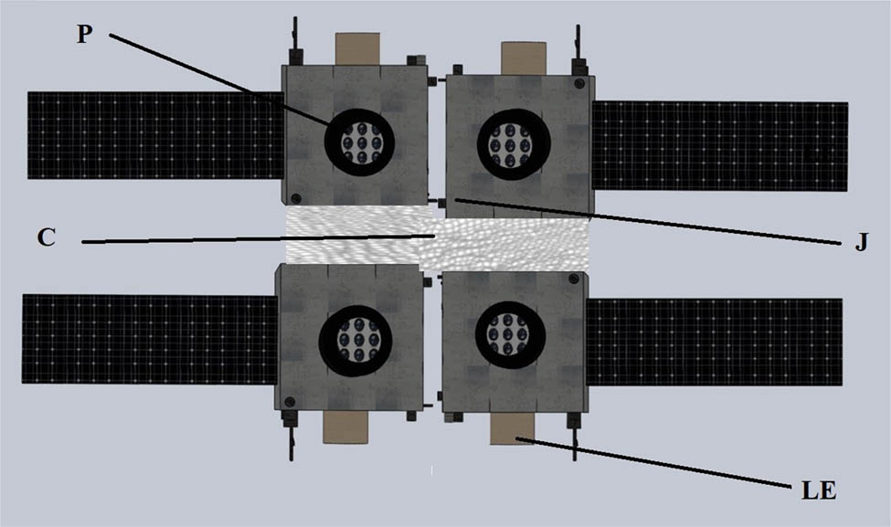
Normal state for the micro/nano joint satellite of high maneuverability. P: remote sensing payload; LE: large-thrust engine; C: depositary cabin of the removal net, and J: joint connection mechanism.
C is a depositary cabin for storing the removal net, where it is tightly compressed. It unfolds as shown in Figure 7. LE refers to the main propeller. Two groups of propellers for each node satellite are located symmetrically outside the satellite, as shown in Figure 6, which shows the normal state.

Space debris removal by the micro/nano joint satellite (unfolding of the net).
4.2 Removing state of the joint satellite
When the joint satellite is instructed to perform removal, the satellite first maneuvers at rapid speed to the debris and then observes the debris at a near distance.
Once the joint satellite enters the remove scope, the node satellites separate in accordance with micro/nanosatellite maneuvering separation combined with locking mechanism separation. Then, explosive devices mounted on the node satellites ignite and break the link that fastens the removal net. At that point, the net unfolds with the four node satellites stretching out toward the four angles in a quadrangle. As shown in Figure 7, the node satellites, are jointly controlled by data collaboration, perform near-field communication via the antenna after the net has been unfolded and remove the debris by manipulating the net.
If debris contacts the net or moves into the encircled region of the net, the net closes up by joint maneuvering of the four node satellites. Because the four node satellites are maneuverable, after the joint pulls the debris to the gravel yard orbiter, the debris is directed slowly and safely into the atmosphere, and the node satellites extend the net and speed up reversely to separate the joint and the debris.
5 Satellite features
The features include superior data discrimination of identified debris by the four remote sensing cameras of the nodes with great accuracy.
They also include two pairs (four) of oppositely placed engines that maneuver rapidly toward the debris when the net is ready for removal.
When the joint satellite separates and moves into four corners of a rectangle, it quickly sets free the net stored in the depositary cabin of the joint satellite to remove the debris.
Rotating debris can be removed effectively. Four node satellites separate from the joint satellite and pull the net with tethers. Since the four satellites are all available for remote sensing and maneuvering, the net dynamically rotates, and its shape can be changed at any time under the pulling of the node satellites.
Because the joint deorbits the debris by reopening the net, the net is reusable as long as no damage arises from the debris in the removal process.
6 Conclusion and key difficulties
This article explores a micro/nano joint satellite with high maneuverability for space debris removal. The joint satellite is composed of four node satellites that are available for debris recognition and strong maneuverability. The joint satellite can be used in daily operation and is responsible for observing the debris. When removing the debris, the joint satellite separates and unfolds the net for the task. Compared with a normal satellite, a joint satellite is favored for its faster maneuverability and higher flexibility.
The focus of planned future studies is to target a more complicated removal net and a joint satellite that may consist of 6, 8, 10, or 16 satellite nodes. The modularization design for micro/nanosatellite should be taken into account to reduce the production cost and shorten the production cycle. Demanding observation and changeable debris call for modularization of the interfaces interlinking 6–16 satellite nodes. Intersatellite data transmission is challenging, possibly requiring distributed computation by interspersing a robust data bus in the removal net.
In terms of joint dynamic orbit transformation and the removal net shape, four degrees of freedom will be explored for integrated six and even eight degrees of freedom control of the joint satellite (Liu et al. 2012).
Small debris is of millimeter-level size, and the explosion plume generated by the explosion of the explosive device is limited; however, the explosion plume affects the explosion in a limited manner. When the joint satellite separates, the net expands because of node satellite engine thrust. The connection functions as a physical link for fixing the net, and it can be disconnected by less destructive force. In addition, to reduce the debris and the impact on the satellite and space environment, a follow-up simulation and experiment will be included in the studies of micro/nanosatellite maneuvering separation combined with locking mechanism separation.
When the joint consists of more node satellites, more tethers are needed to pull the removal net. When one or more unstable debris with various shapes, speeds, and incident directions contact the net, the force analysis and motion characteristic analysis of the whole joint satellite become complicated (Jiang et al. 2020).
-
Funding information: The authors state no funding involved.
-
Author contributions: All authors have accepted responsibility for the entire content of this manuscript and approved its submission.
-
Conflict of interest: The authors state no conflict of interest.
References
Aslanov V, Yudintsev V. 2013. Dynamics of large space debris removal using tethered space tug. Acta Astronaut. 91(10):149–156.10.1016/j.actaastro.2013.05.020Suche in Google Scholar
Biesbroek R, Innocenti L, Wolahan A, Serrano SM. 2017. e.Deorbit-ESAs active debris removal mission. 7th European Conference on Space Debris. Dormstadt, Germany.Suche in Google Scholar
Bingyao L, Peng S, Yufei X, Yushan Z. 2021. Switching LPV control for electromagnetic formation flying on highly elliptical orbit. Astrodynamics. 5:373–389.10.1007/s42064-021-0117-xSuche in Google Scholar
Clean Space. 2022. http://www.esa.int/Our_Activities/Space_Engineering_Technology/Clean_Space.Suche in Google Scholar
ESA Space Debris Office. 2017. ESAs Annual Space Environment Report. European Space Agency.Suche in Google Scholar
Gong Z, Gao K, Song G, Li M, Wu Q, Cao Y, et al. 2018. Research progress and prospect of hypervelocity impect and its space application. Mod Appl Phys. 9(4):11–23.Suche in Google Scholar
Jiang Y, Li H, Yang Y. 2020. Evolution of space debris for spacecraft in the Sun-Synchronous orbit. Open Astron. 29(1):265–274.10.1515/astro-2020-0024Suche in Google Scholar
Jiang Y. 2020. Debris cloud of India anti-satellite test to Microsat-R satellite. Heliyon. 6(8):e04692.10.1016/j.heliyon.2020.e04692Suche in Google Scholar PubMed PubMed Central
Johnson-Freese J, Burbach D. 2019. The outer space treaty and the weaponization of space. Bull Sci. 75(4):137–141.10.1080/00963402.2019.1628458Suche in Google Scholar
Krag H, Serrano M, Braun V, Kuchynka P, Catania M, Siminski J, et al. 2017. A 1 cm space debris impact onto the sentinel-1a solar array. Acta Astronaut. 137:434–443.10.1016/j.actaastro.2017.05.010Suche in Google Scholar
Kurihara M, Higashide M, Takayanagi Y, Arai K, Yano H, Tabata M, et al. 2015. Impact frequency estimate of micron-sized meteoroids and debris on Tanpopo capture panels on the ISS. Proc Eng. 103:334–340.10.1016/j.proeng.2015.04.055Suche in Google Scholar
Lanouette AM, Potvin MJ, Martin F, Houle D, Therriault D. 2015. Residual mechanical properties of a carbon fiber/PEEK space robotic arm after simulated orbital debris impact. Int J Impact Eng. 84:78–87.10.1016/j.ijimpeng.2015.05.010Suche in Google Scholar
Li M, Gong Z, Liu G. 2018. Frontier technology and system development of space debris surveillance and active removal. Chin Sci Bull. 63(25):2570–2591.10.1360/N972017-00880Suche in Google Scholar
Liou JC, Johnson NL. 2006. Planetary science. Risks Space Orbiting Debris Sci. 311(5759):340–341.10.1126/science.1121337Suche in Google Scholar
Liu S, Lan SW, Zhaoxia M, Li Y. 2012. Experimental study on characteristics of satellite breakup debris. J Astronaut. 33(9):1347–1353.Suche in Google Scholar
Martin G. 2019. Anti-satellite weapons driving the militarisation of space. Asia Pac Def Rep. 45(6):40.Suche in Google Scholar
Pardini C, Anselmo L. 2017. Revisiting the collision risk with cataloged objects for the Iridium and COSMO-SkyMed satellite constellations. Acta Astronaut. 134:23–32.10.1016/j.actaastro.2017.01.046Suche in Google Scholar
Qi R, Misra AK, Zuo Z. 2017. Active debris removal using double tethered space-tug system. J Guid Control Dynam. 40(3):720–728.10.2514/1.G000699Suche in Google Scholar
Rossi A, Cordelli A, Farinella P, Anselmo L. 1994. Collisional evolution of the Earth’s orbital debris cloud. J Geophys Res Plan 99(E11):23195–23210.10.1029/94JE02320Suche in Google Scholar
Rubenchik AM, Fedoruk MP, Turitsyn SK. 2014. The effect of self-focusing on laser space-debris cleaning. Light Sci Appl. 3(4):e159.10.1038/lsa.2014.40Suche in Google Scholar
Schonberg WP. 2001. Characterizing secondary debris impact ejecta. Int J Impact Eng. 26(1–10):713–724.10.1016/S0734-743X(01)00117-8Suche in Google Scholar
Shuai G, Zhou W, Zhang J, Sun F, Yu D. 2021. Integrated constellation design and deployment method for a regional augmented navigation satellite system using piggyback launches. Astrodynamics. 5(1):49–60.10.1007/s42064-020-0091-8Suche in Google Scholar
Vadali SR. 2002. An analytical solution for relative motion of satellites. The 5th International conference on dynamics and control of systems and structures in space. Cranfield Univ.: Cranfield, UK. p. 309–316.Suche in Google Scholar
Vallduriola GV, Surez Trujillo DA, Helfers T, Daens D, Utzmann J, Pittet JN, et al. 2018. The use of streak observations to detect space debris. Int J Remote Sens. 39(7):2066–2077.10.1080/01431161.2017.1407502Suche in Google Scholar
Yan N, Tang Q, Chen R, Li Y. 2018. Development of European space debris removal technologies. Space Debris Res. 18(2):14–22.Suche in Google Scholar
Zhang Y, Yu Y, Hexi B. 2021. Dynamical behavior of flexible net spacecraft for landing on asteroid. Astrodynamics. 5(3):249–261.10.1007/s42064-021-0102-4Suche in Google Scholar
© 2022 Yuan An et al., published by De Gruyter
This work is licensed under the Creative Commons Attribution 4.0 International License.
Artikel in diesem Heft
- Research Articles
- Deep learning application for stellar parameters determination: I-constraining the hyperparameters
- Explaining the cuspy dark matter halos by the Landau–Ginzburg theory
- The evolution of time-dependent Λ and G in multi-fluid Bianchi type-I cosmological models
- Observational data and orbits of the comets discovered at the Vilnius Observatory in 1980–2006 and the case of the comet 322P
- Special Issue: Modern Stellar Astronomy
- Determination of the degree of star concentration in globular clusters based on space observation data
- Can local inhomogeneity of the Universe explain the accelerating expansion?
- Processing and visualisation of a series of monochromatic images of regions of the Sun
- 11-year dynamics of coronal hole and sunspot areas
- Investigation of the mechanism of a solar flare by means of MHD simulations above the active region in real scale of time: The choice of parameters and the appearance of a flare situation
- Comparing results of real-scale time MHD modeling with observational data for first flare M 1.9 in AR 10365
- Modeling of large-scale disk perturbation eclipses of UX Ori stars with the puffed-up inner disks
- A numerical approach to model chemistry of complex organic molecules in a protoplanetary disk
- Small-scale sectorial perturbation modes against the background of a pulsating model of disk-like self-gravitating systems
- Hα emission from gaseous structures above galactic discs
- Parameterization of long-period eclipsing binaries
- Chemical composition and ages of four globular clusters in M31 from the analysis of their integrated-light spectra
- Dynamics of magnetic flux tubes in accretion disks of Herbig Ae/Be stars
- Checking the possibility of determining the relative orbits of stars rotating around the center body of the Galaxy
- Photometry and kinematics of extragalactic star-forming complexes
- New triple-mode high-amplitude Delta Scuti variables
- Bubbles and OB associations
- Peculiarities of radio emission from new pulsars at 111 MHz
- Influence of the magnetic field on the formation of protostellar disks
- The specifics of pulsar radio emission
- Wide binary stars with non-coeval components
- Special Issue: The Global Space Exploration Conference (GLEX) 2021
- ANALOG-1 ISS – The first part of an analogue mission to guide ESA’s robotic moon exploration efforts
- Lunar PNT system concept and simulation results
- Special Issue: New Progress in Astrodynamics Applications - Part I
- Message from the Guest Editor of the Special Issue on New Progress in Astrodynamics Applications
- Research on real-time reachability evaluation for reentry vehicles based on fuzzy learning
- Application of cloud computing key technology in aerospace TT&C
- Improvement of orbit prediction accuracy using extreme gradient boosting and principal component analysis
- End-of-discharge prediction for satellite lithium-ion battery based on evidential reasoning rule
- High-altitude satellites range scheduling for urgent request utilizing reinforcement learning
- Performance of dual one-way measurements and precise orbit determination for BDS via inter-satellite link
- Angular acceleration compensation guidance law for passive homing missiles
- Research progress on the effects of microgravity and space radiation on astronauts’ health and nursing measures
- A micro/nano joint satellite design of high maneuverability for space debris removal
- Optimization of satellite resource scheduling under regional target coverage conditions
- Research on fault detection and principal component analysis for spacecraft feature extraction based on kernel methods
- On-board BDS dynamic filtering ballistic determination and precision evaluation
- High-speed inter-satellite link construction technology for navigation constellation oriented to engineering practice
- Integrated design of ranging and DOR signal for China's deep space navigation
- Close-range leader–follower flight control technology for near-circular low-orbit satellites
- Analysis of the equilibrium points and orbits stability for the asteroid 93 Minerva
- Access once encountered TT&C mode based on space–air–ground integration network
- Cooperative capture trajectory optimization of multi-space robots using an improved multi-objective fruit fly algorithm