Finite element analysis of deterioration of axial compression behavior of corroded steel-reinforced concrete middle-length columns
-
Renjie Nie

 ,
Libo Chen
,
Libo Chen

Abstract
The corrosion problem of steel-reinforced concrete (SRC) columns in coastal areas is becoming increasingly severe and needs to be solved urgently. This study established a numerical analysis model for SRC middle-length columns considering corrosion effects. The bond–slip constitutive relationship between corroded steel and concrete was established. It was found that when the rust rate is low, the bonding stress of SRC columns is slightly increased compared to those without corrosion. The ultimate and residual bonding stress will decrease significantly when the rust rate exceeds 1.5%. The comparison between the numerical analysis model and the experimental results shows that the establishment of the model is reasonable. Subsequent parameter analysis showed that for corroded SRC mid-length columns, the larger the slenderness ratio of the component, the faster the decrease in axial compression performance. The rust rate increased from 0 to 30%, and the axial compression performance of SRC columns decreased significantly. When the rust rate exceeded 30%, the axial compression performance of concrete columns tended to stabilize. A formula for calculating SRC middle-length columns’ ultimate bearing capacity considering corrosion effects has been proposed.
1 Introduction
Compared to reinforced concrete structures (RC), steel-reinforced concrete (SRC) composite structures have a lower weight, smaller section size, better mechanical performance, and the ability to effectively minimize the axial compression ratio of components because the built-in steel is integrated into the structure [1]. SRC columns are stiffer laterally and fire-resistant than steel structures, and they also use less steel, delivering good economic benefits [2,3,4]. Because of its seismic solid performance and excellent bearing capacity, it is widely used in large-span and high-rise buildings [5,6,7]. Compared to steel-concrete composite tube structures composed of ultra-high performance nano-concrete, SRC structures have lower raw material costs and are more widely applicable [8].
However, with the continued application of the SRC columns in coastal areas, corrosion has become a severe problem. SRC middle-length columns are easily corroded by corrosive gases [9,10,11,12] and ions [13,14,15,16]. Corrosion produces corrosion products that generate stress that causes structural damage and a shrinking steel sectional area inside the SRC middle-length columns [17,18], which affects the components’ stability and axial compressive bearing capacity and shortens their service life [19,20], posing significant safety risks and leading to economic losses. Hou et al. [21] estimated that the cost of corrosion in China was approximately 2127.8 billion RMB (∼ 310 billion USD), representing about 3.34% of the gross domestic product (GDP). KOCH’s [22] studies arrived at corrosion costs equivalent to about 3–4% of each nation’s GDP. The global cost of corrosion can then be estimated to be US$2.5 trillion. It is estimated that savings of between 15 and 35% of the cost of corrosion could be realized, i.e., between US$375 and $875 billion annually on a global basis by using available corrosion control practices.
Much research on the effect of corrosion on reinforced concrete have focused on the bond strength between the corroded steel bars and concrete [23,24,25,26,27,28]. This article focuses on the level of constitutive relationship, proposes the bond-slip constitutive relationship between steel bars and concrete based on the research by Zhao et al. [29], and summarizes the influence of corrosion degree on the ultimate bond stress and residual bond stress between steel bars and concrete. Scholars have also researched the mechanical properties of corroded reinforced concrete [30], but the research mainly focuses on beam structures. In response to the current lack of attention to the mechanical properties of SRC middle-length columns, research has been conducted on the axial compression capacity of SRC middle-length columns. In addition, Jiang et al. [31] proposed a formula for calculating the shear-bearing capacity of corroded reinforced concrete beams. This article proposes a formula for calculating long columns’ ultimate axial compressive bearing capacity in SRC.
This article established a numerical analysis model for corroded SRC middle-length columns using ABAQUS, a finite element analysis platform. This model considered the impact of bonding strength degradation on corroded steel reinforcing columns [29]. It revealed the negative impact of corrosion and slenderness ratios on the loading capacity of SRC columns under axial compression. Next it confirmed good consistency between simulation and experimental results, demonstrating the validity of the numerical analysis model. Furthermore, the parameter range is broadened to study the influences of slenderness ratio and rust rate on the bearing capacity of the corroded SRC columns. Finally, the study proposed a formula to calculate the bearing capacity of SRC middle-length columns, considering the influence of corrosion, and verified the formula.
2 Considering the influence of corrosion: Numerical simulation
2.1 Standardized selection
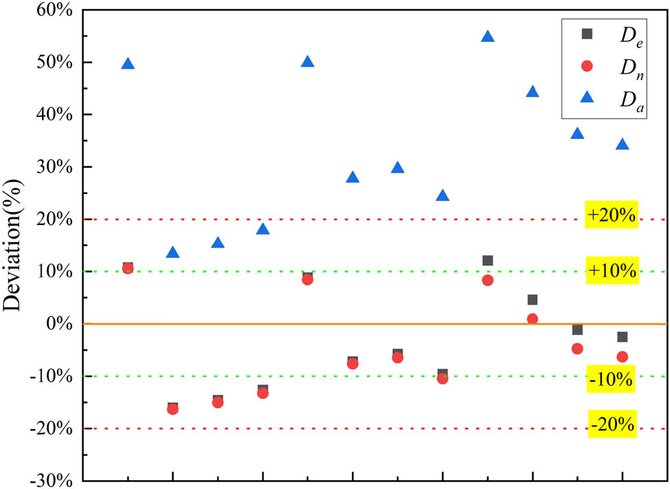
The ultimate bearing capacity of reinforced concrete columns with different degrees of corrosion was calculated using Chinese [32], American [33], and European [34] standards. Based on the corrosion test conducted in the following text to verify the accuracy of the established finite element model (as the test details are described in detail in the finite element verification, there will be no further explanation here. The test includes 12 SRC mid-length columns, of which 3 are uncorroded and 9 are corroded). The ultimate bearing capacity of reinforced concrete columns are compared with different degrees of corrosion obtained from the standard and experimental results, as shown in Figure 1. The deviation rate between specifications and tests is calculated using Eqs (1)–(3).
Comparison of ultimate bearing capacity between normative and experimental results.
From Figure 1, it can be seen that the calculation and experimental results of the European and Chinese standards are closest. In contrast, the American standard has the most significant difference between the calculated and experimental results. Chinese standards are more suitable for solving the corrosion problem of reinforced concrete in China, so Chinese standards were chosen.
where N u.e is the ultimate bearing capacity result calculated by European standards, N u.n is the ultimate bearing capacity result calculated by Chinese standards, N u.a is the ultimate bearing capacity calculation result calculated by American standards, D e represents the deviation rate between European standards and test results, D n represents the deviation rate between Chinese standards and test results, and D a represents the deviation rate between American standards and test results.
2.2 Constitutive relation of concrete
The following steps are involved in the investigation of the concrete’s uniaxial compression and tensile stress–strain relationships in unconstrained areas. Various parameters should be selected based on the Chinese standard GB 50010-2010 [32].
The stress–strain relationship of concrete under uniaxial compression is estimated using Eqs (4) and (5).
where E c is the elastic modulus of concrete, σ c denotes the compressive stress of the concrete, ε c represents the compressive strain of concrete; α c is the parameter value of the descending section of the stress–strain curve of concrete under uniaxial compression, f c.r is the value of the uniaxial compressive strength of concrete, ε c.r stands for the peak compressive strain of the concrete with the uniaxial compressive strength f c.r, and d c represents the damage evolution parameter.
The stress–strain relationship of concrete under uniaxial tension is calculated by Eq. (6).
The developed parameters of tensile damage are calculated by Eq. (7).
where σ t represents the concrete’s tensile stress, ε t denotes its tensile strain, α t is the parameter value of the reduced section of the concrete’s uniaxial tensile stress–strain curve, chosen by the specifications, f t.r stands for the concrete’s uniaxial tensile strength, ε t.r represents the concrete’s peak tensile strain, which is related to the uniaxial tensile strength f t.r, and d t is the evolution parameter of the concrete’s uniaxial tensile damage.
For corroded SRC columns [35], Eq. (8) is used to calculate the compressive strength of the concrete protective layer.
where
The calculated concrete strength improvement coefficient in the constraint area is substituted in the Mander constraint area concrete model [36]. The stress–strain curve of the concrete in different constraint areas after corrosion occurs is obtained as shown in Figure 2. k
1 and k
2 are the improvement coefficients of the concrete strength in the stirrup constraint area and the composite constraint area, respectively, and ε
cc1 and ε
cc2 are the peak strains related to the peak stress of the concrete in the stirrup constraint area and the concrete in the composite constraint area, respectively;
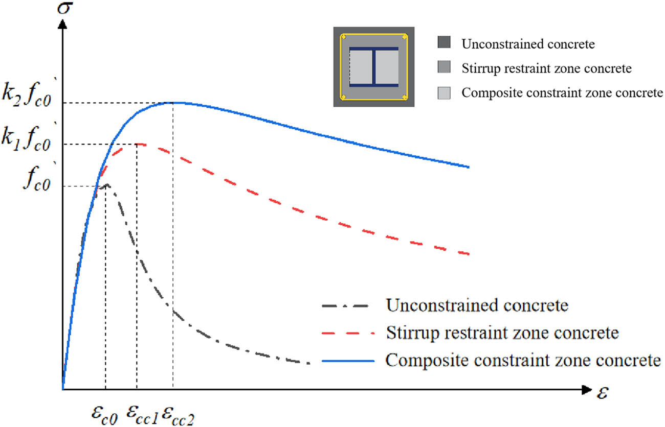
Stress–strain curve of confined concrete considering corrosion.
The parameters of the plastic damage model of the concrete [37] are shown in Table 1. Eqs (9) and (10) can be used to obtain the concrete damage factor.
where
Concrete damage plasticity model parameter inputs
| Expansion angle | Eccentricity | f b0/fc0 | K | Viscosity parameter |
|---|---|---|---|---|
| 30 | 0.1 | 1 | 0.6666667 | 0.001 |
2.3 Constitutive relation of steel
Figure 3(a) displays the stress–strain relation of section steel, and the parameters are shown in Table 2. To simplify the stress–strain curve, we divided it into four stages: the elastic section (OA), the plastic section (AB), the strengthening section (BC), and the secondary plastic flow section (CE). The strengthening section (BC) is regarded as a straight section to facilitate input and calculation. As shown in Table 2, f y is the yield strength of the steel and f u represents the ultimate strength of the steel. The stress–strain relationship of steel bars is shown in Figure 3(b), and the parameters are shown in Table 3, in which simplified dotted lines are used. If the slope of AB is 1, then the slope of OA is 100.

Stress–strain curve of steel. (a) Stress–strain curve of section steel. (b) Stress–strain curve of steel bar.
Constitutive of section steel
| Steel grade | E (MPa) | f y (MPa) | f u (MPa) | ε y | ε s | ε u |
|---|---|---|---|---|---|---|
| Q235 | 201,000 | 261 | 407 | 0.00107 | 0.00125 | 0.0940 |
Constitutive of steel bar
| Steel grade | E (MPa) | f y (MPa) | ε y |
|---|---|---|---|
| HRB400 | 216,000 | 439 | 0.00203 |
| HPB300 | 212,000 | 352 | 0.00166 |
The von Mises yield criterion is used to determine the stress state of the steel, and Eq. (11) is used to determine whether the steel enters the yield state.
where σ 1, σ 2, and σ 3 are the first, the second, and the third principal stresses, respectively.
2.4 Bond-slip constitutive relation between the section steel and the concrete
The typical bond stress–strain curve of SRC was divided into four main stages, as shown in Figure 4 [38]: the non-slip stage (OA), the slip stage (AB), the descent stage (BC), and the residual bond force stage (CD). The ordinate value of feature point A′ is 0.5 (τ S + τ u).
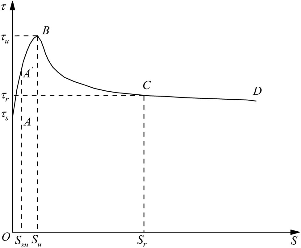
Typical bond stress–slip curve of SRC structure.
The initial bond-slip strength can be obtained by Eq. (12).
The ultimate bond strength can be obtained by Eq. (13).
Eq. (14) shows the residual bond strength.
where C ss stands for the thickness of the concrete protective layer for the section steel, d represents its height, L e is its embedded length, ρ sv denotes the reinforcement ratio, and f t is the tensile strength of the concrete.
Eqs (15)–(17) are used to calculate the slip value of each point.
where S su represents the slip amount of the control point A′, S u is the slip amount of the maximum bonding stress, and S r is the slip amount of the starting point at the residual bonding stress stage.
Therefore, the bond–slip curve of the SRC can be obtained. Table 4 shows the curve’s parameters, and Figure 5 shows the bond–slip curves of specimens with different slenderness ratios.
Bond slip characteristic parameters of specimens with different slenderness ratios
| Order number | L e | τ s | τ u | τ r | S su | S u | S r |
|---|---|---|---|---|---|---|---|
| 1 | 600 | 1.145 | 1.472 | 0.536 | 0.112 | 0.246 | 1.630 |
| 2 | 1,000 | 0.919 | 1.375 | 0.536 | 0.187 | 0.410 | 2.717 |
| 3 | 1,400 | 0.693 | 1.278 | 0.536 | 0.262 | 0.574 | 3.803 |
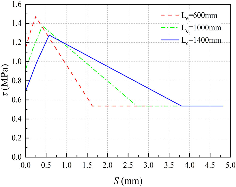
Bond–slip curve of specimens with different slenderness ratios.
Eq. (18) considers the impact of corrosion on the bond strength of SRC.
Eq. (19) shows the bonding strength after corrosion.
After calculation, the bond–slip curves with different slenderness ratios and corrosion rates can be obtained, as shown in Figure 6. In comparison to an SRC column without corrosion, the bond stress will marginally rise when the rust rate is low, but the ultimate bond stress and residual bond stress will both decline sharply as the rust rate continues to increase. The reason for the above phenomenon is that at the beginning of the steel corrosion, the rust products fill the small gaps between the steel and concrete, increasing the contact area between the steel and concrete, thereby improving the bonding stress between the steel and concrete. As the rust rate continues to increase, the rust products spread across the surface of the steel, causing the steel and concrete to detach from the bond, resulting in a significant decrease in bonding stress.
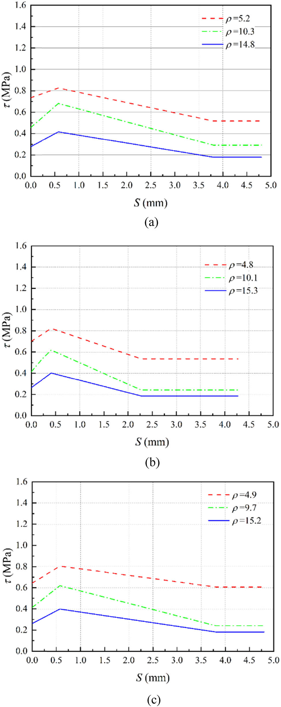
Considering bond deterioration τ–S curve. (a) Bond–slip curve of 0.6 m SRC columns. (b) Bond–slip curve of 1.0 m SRC columns. (c) Bond–slip curve of 1.4 m SRC columns.
2.5 Cell type selection
Concrete, steel sections, and base plates use C3D8R eight-node linear hexahedral linear reduced integral solid elements, containing only one integration point at the element’s center. The advantage is that it is less prone to shear self-locking linearity under bending loads, and the displacement solution results are relatively accurate. When there is twisting deformation in the grid, the accuracy of the analysis will not be significantly affected. The longitudinal reinforcement and hoop reinforcement use a T3D2 two-node linear three-dimensional truss, Truss element, which can only withstand axial forces and cannot withstand bending moments and shear forces. It can effectively simulate the tensile and compressive behavior of the hoop reinforcement.
Relative sliding between the section steel and the concrete quickly occurs when the SRC structure is under load. To reflect this bond–slip relationship in the finite element model, we have established a spring2 element with nonlinear stiffness between the section steel and the concrete. In spring2, the spring element
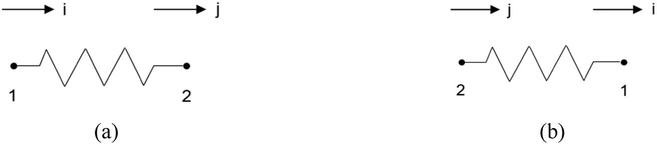
Spring node sequence setting. (a) Compression spring. (b) Tension spring.
2.6 Parts and grid division
The SRC column can be divided into components with different material properties: the reinforcement cage, the section steel, and the concrete, as shown in Figure 8. Different material properties should be assigned to different constraint areas of the concrete. The split geometric element command is used to divide the constrained concrete into three different areas: the unconstrained area, the stirrup constraint area, and the composite constraint area, as shown in Figure 9. The grid size of the SRC column cross-section and the grid size along the height direction are set to be around 25 mm.
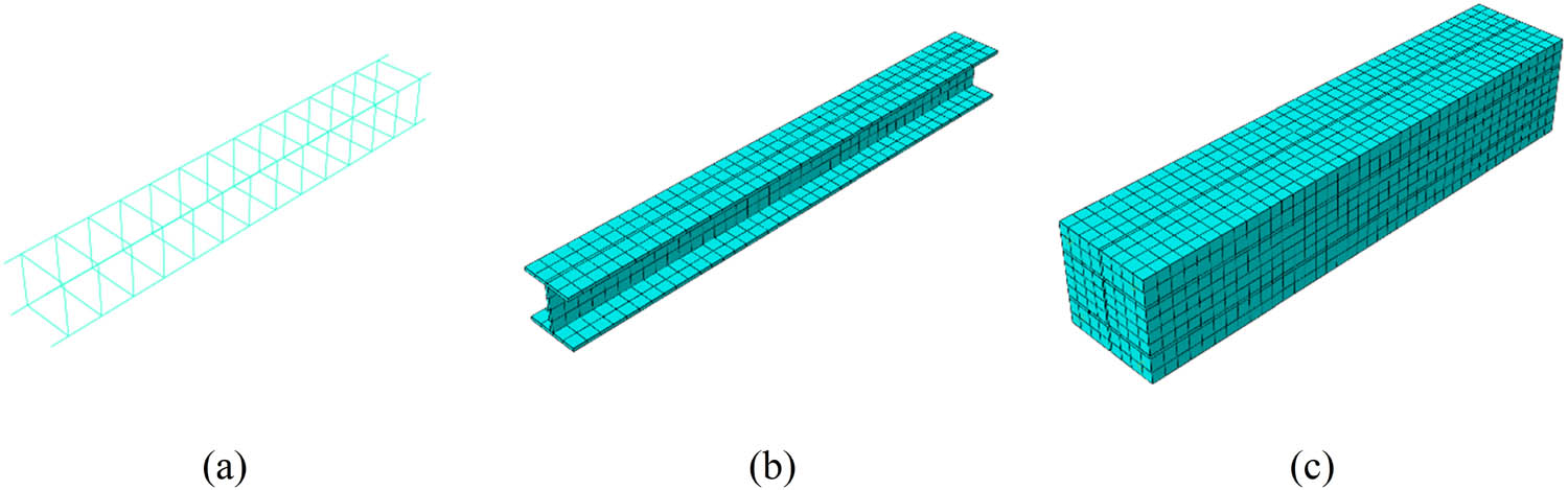
Parts and grid division. (a) Reinforcement cage. (b) Section steel. (c) Concrete.
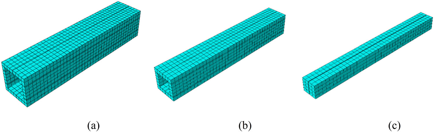
Division of concrete constraint areas. (a) Concrete in the unconstrained area. (b) Concrete in the stirrup constraint area. (c) Concrete in composite constraint area.
2.7 Interaction and boundary conditions
The longitudinal, transverse, and everyday interactions between the section steel and the concrete should be considered separately. In other words, spring units and their corresponding spring stiffness should be established in these three directions. Among them, the longitudinal springs are highly crucial to numerical analysis, and the bond–slip curve defined earlier is the longitudinal slip between the section of steel and the concrete. To reflect this nonlinear relationship in the spring element, it is necessary to define the spring’s F–u curve in the inp file of ABAQUS, which indicates the relative displacement between the spring force and the spring node. The bond–slip curve shows the relation between stress τ and slip S, and stress τ should be converted to force F based on Eq. (20).
where A i is related to the spring position at the node and the unit area size, as shown in Figure 10. Moreover, 1/4 of the area of each unit at the node location is added following Eqs. (21)–(23).
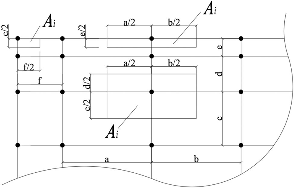
A i area calculation.
Middle node:
Edge node:
Corner nodes:
The steel web plate and flange should be considered separately for transverse springs. Due to the constraint effect of the flange at the web position, there is no relative sliding between the section steel and concrete with a more considerable spring stiffness value. The lateral slip at the flange is similar to the longitudinal slip, and its spring stiffness value is the same as that of the longitudinal one. As the characteristics of concrete materials are a necessary factor of standard springs, a compression spring with high stiffness can be set, and the spring stiffness can be taken to approximate the elastic modulus of concrete. The distribution of spring nodes in the SRC column is shown in Figure 11.
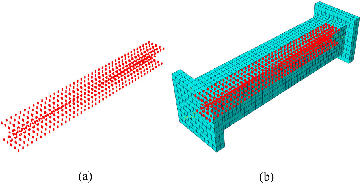
Distribution position of spring nodes. (a) Spring node. (b) The distribution of spring nodes in SRC columns.
The slip between steel bars and the concrete can be neglected. The steel mesh is embedded into the concrete to realize the coordinated deformation between the concrete and steel bars. The regular contact relationship between the two ends of the cushion plate and the surface of the SRC column is challenging to contact, and the cushion plate is bound to the upper and lower end faces of the SRC column to prevent rigid displacement of the column body. As shown in Figures 12 and 13, a reference point coupled with the upper surface of the column upper cushion plate is created, locking all displacement and angular degrees of freedom of the SRC column lower cushion plate. To simulate the movement of the loading end during the testing, displacement control is adopted to apply the axial load.
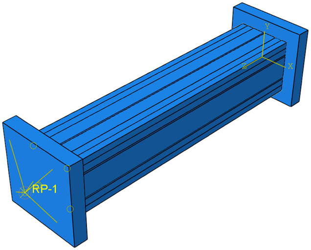
Reference point coupling.
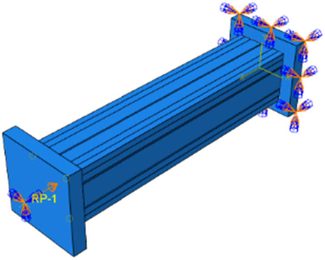
Boundary condition settings.
2.8 Finite element model validation
To verify the reliability of the finite element model, 12 middle-length SRC columns were designed and manufactured based on the established model parameters. The specimen’s dimensions and the steel bars’ arrangement are shown in Figure 14. The on-site images of the experiment are shown in Figures 15–17. The study variables include the corrosion time, the corrosion current magnitude, the concentration of chloride ions, and the slenderness ratio of the SRC columns. In addition, electrochemical accelerated corrosion tests were conducted on nine SRC middle-length columns, axial compression tests on corroded middle-length SRC columns, and non-corroded control group specimens. The accelerated corrosion test scheme adopted the total immersion method. First, the wooden template with the upper opening was made, and sufficient NaCl solution was added. The specimen was then placed into the wooden template. Before powering on, two stainless steel rods are arranged at both ends of the SRC column, and wires connect the stainless steel rods to the power cathode. The pre-embedded wires inside the SRC column are connected to the power anode. Adjust the power supply to constant current mode and start powering on. All SRC specimens are numbered according to the above four parameters to identify specimens better. Table 5 shows the details. For example, “D9-CL3.5-EC8.0-L0.6” defines the following parameters:
“D9” refers to 9 days of corrosion time.
“CL3.5” indicates that the solution’s chloride ion concentration is 3.5%.
“EC8.0” means that the corrosion current is 8.0 A.
“L0.6” shows that the SRC column is 0.6 m in height.
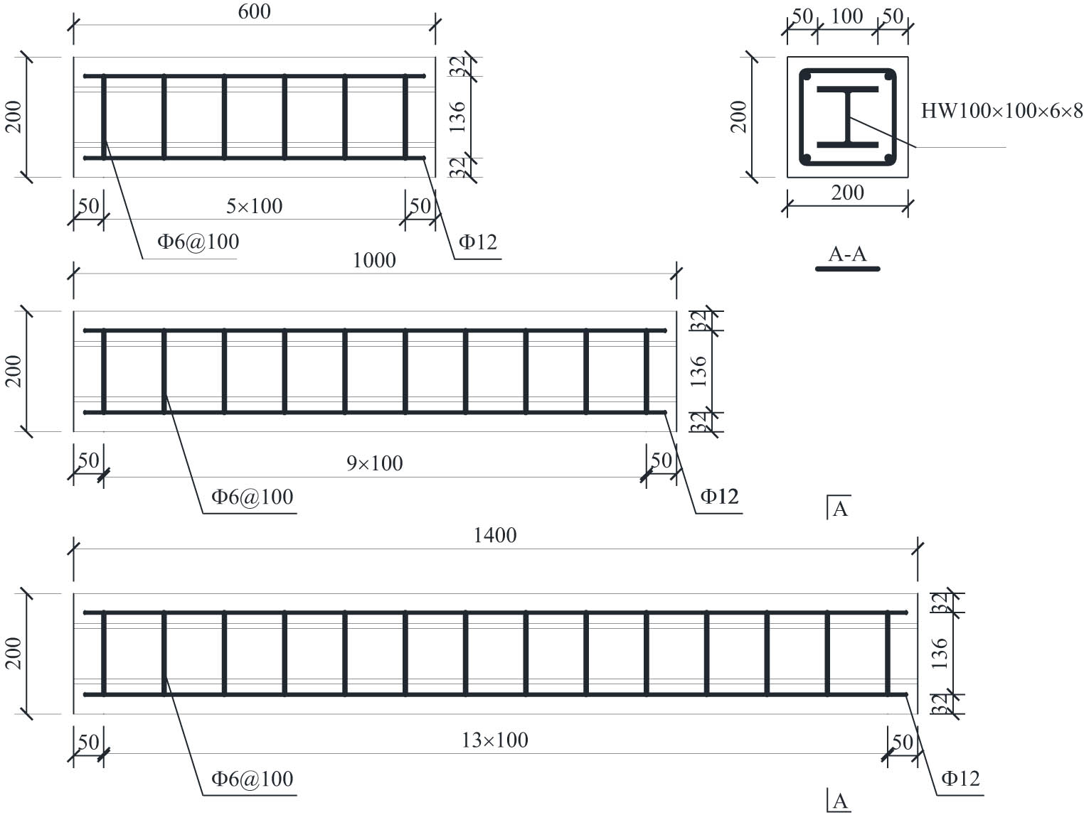
Sample size and reinforcement arrangement.
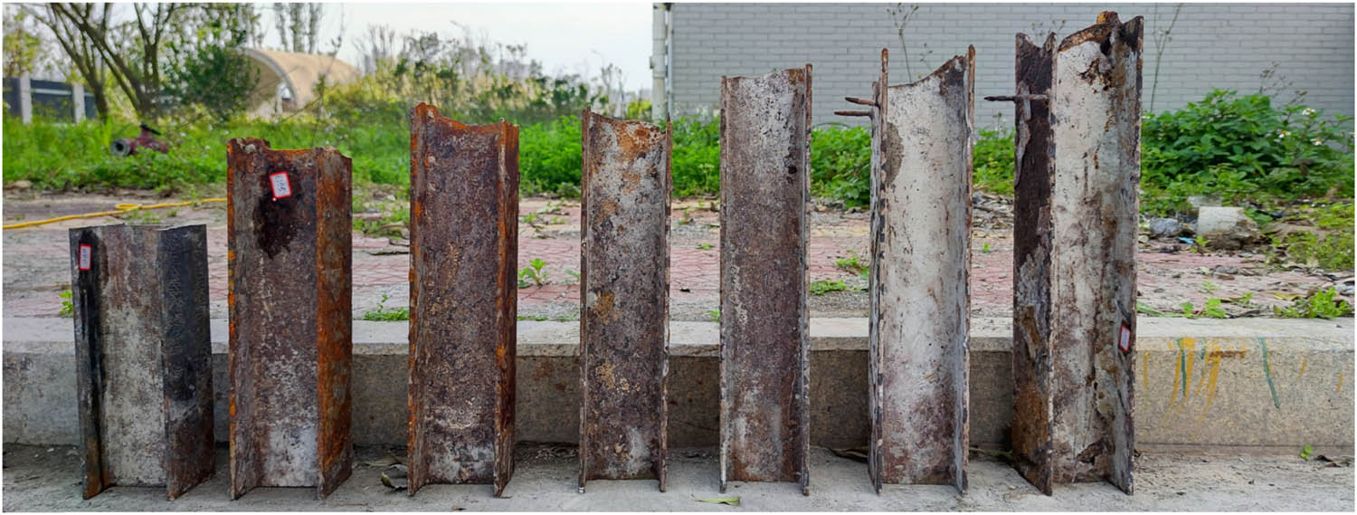
Corrosion of section steel.
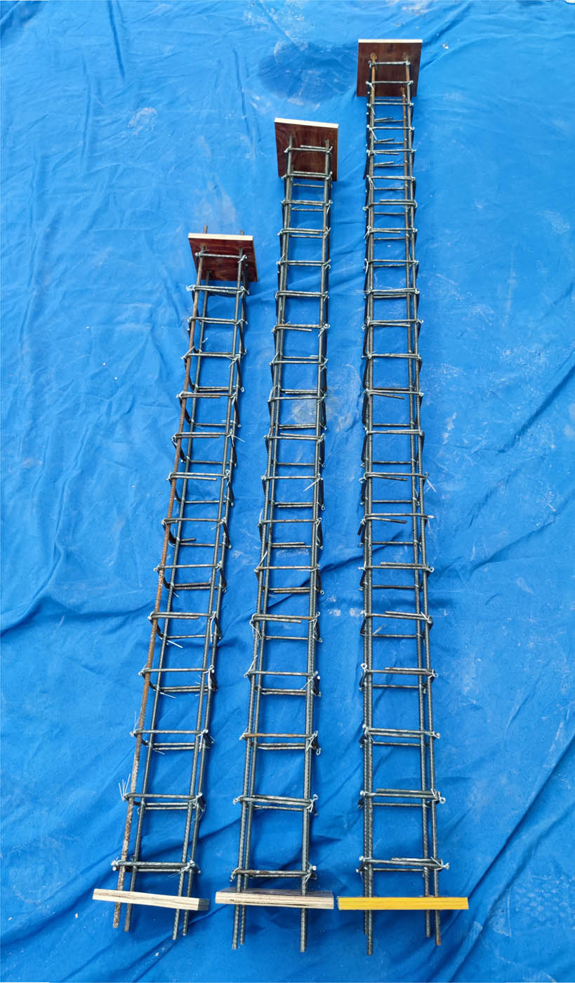
Reinforcement cage.
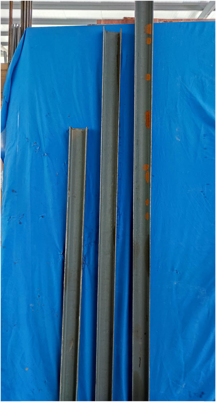
Section steel.
Design parameters of specimen
| Test number | Corrosion time (days) | Chloride ion concentration (%) | Corrosion current (A) | Column height (m) | Slenderness ratio |
|---|---|---|---|---|---|
| D9-CL2.0-EC5.0-L0.6 | 9 | 2 | 5 | 0.6 | 11.12 |
| D9-CL3.5-EC5.0-L0.6 | 9 | 3.5 | 5 | 0.6 | 11.12 |
| D9-CL5.0-EC5.0-L0.6 | 9 | 5 | 5 | 0.6 | 11.12 |
| D6-CL3.5-EC5.0-L1.0 | 6 | 3.5 | 5 | 1.0 | 18.54 |
| D9-CL3.5-EC5.0-L1.0 | 9 | 3.5 | 5 | 1.0 | 18.54 |
| D12-CL3.5-EC5.0-L1.0 | 12 | 3.5 | 5 | 1.0 | 18.54 |
| D9-CL3.5-EC2.0-L1.4 | 9 | 3.5 | 2 | 1.4 | 25.95 |
| D9-CL3.5-EC5.0-L1.4 | 9 | 3.5 | 5 | 1.4 | 25.95 |
| D9-CL3.5-EC8.0-L1.4 | 9 | 3.5 | 8 | 1.4 | 25.95 |
| D0-CL0-EC0-L0.6 | 0 | — | — | 0.6 | 11.12 |
| D0-CL0-EC0-L1.0 | 0 | — | — | 1.0 | 18.54 |
| D0-CL0-EC0-L1.4 | 0 | — | — | 1.4 | 25.95 |
The ABAQUS numerical simulation software was used to conduct axial compression simulation on corroded SRC columns and control groups with monotonic load. Then, comparisons between the load–displacement curves obtained from numerical simulations and the measured load–displacement curves are shown in Figures 18–20. According to the results, the numerical simulation curve is consistent with tests with similar peak loads. In terms of the displacement under the maximum load, the result of the tests is greater than the numerical simulation one.
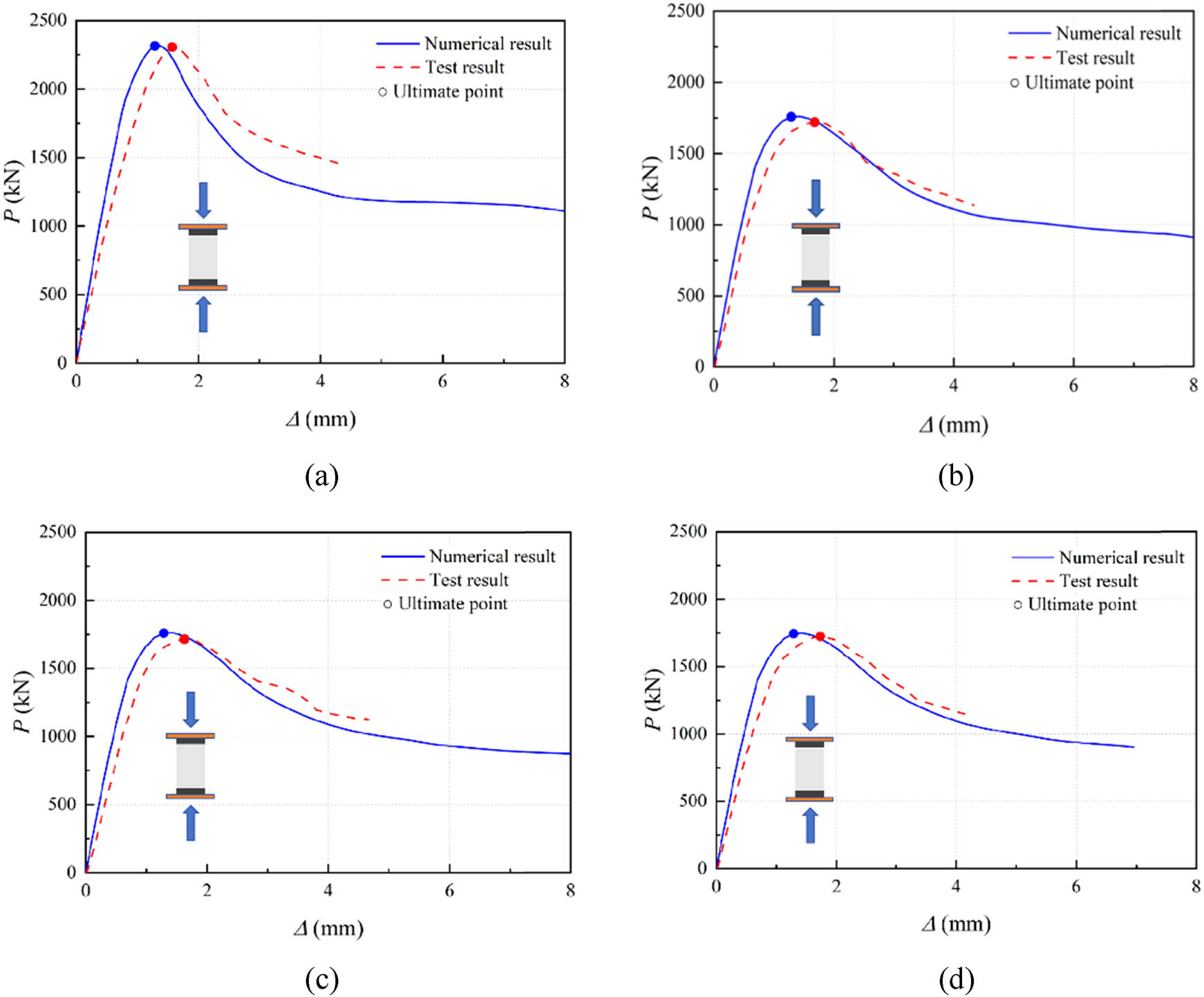
Comparison of finite element method and test load–displacement curve of 0.6 m specimen. (a) D0-CL0-EC0-L0.6. (b) D9-CL2.0-EC5.0-L0.6. (c) D9-C3.5-EC5.0-L0.6. (d) D9-CL5.0-EC5.0-L0.6.
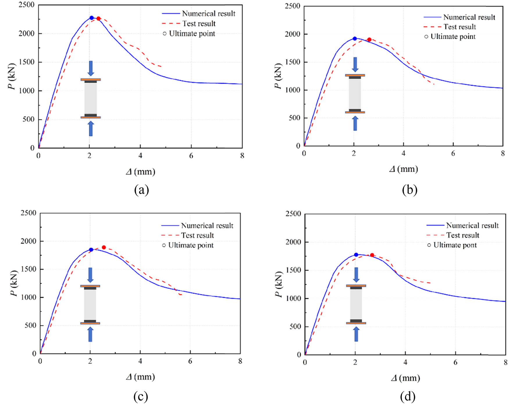
Comparison of finite element method and test load–displacement curve of 1.0 m specimen. (a) D0-CL0-EC0-L1.0. (b) D6-CL3.5-EC5.0-L1.0. (c) D9-CL3.5-EC5.0-L1.0. (d) D12-CL3.5-EC5.0-L1.0.
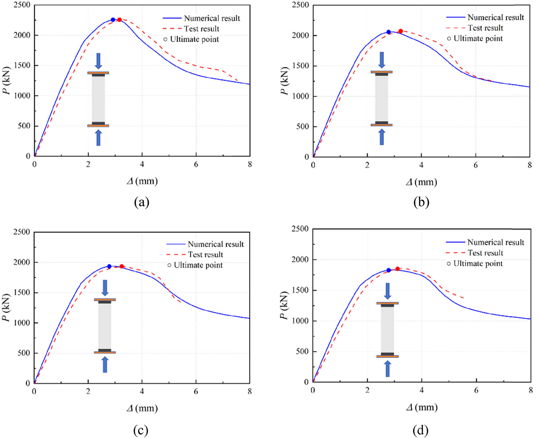
Comparison of finite element method and test load–displacement curve of 1.4 m specimen. (a) D0-CL0-EC0-L1.4. (b) D9-CL3.5-EC2.0-L1.4. (c) D9-CL3.5-EC5.0-L1.4. (d) D9-CL3.5%-EC8.0-L1.4.
Regarding the stiffness of the elastic section, the finite element results are more significant than the experimental ones. Moreover, the descending curve of each specimen after peaking aligns well with the experimental curve. Notably, the error between the two can be explained by neglecting the relative slip between the steel bars and the concrete during the numerical analysis, thus leading to a higher initial stiffness of the SRC column. Furthermore, the material input of each component of the SRC column is isotropic and homogeneous materials, and the discreteness of the concrete material under actual working conditions will also affect simulation results. Due to these initial negative factors and the incomplete planar contact between the loading end and the end section of the SRC column during testing, some gaps result in displacement, corresponding to the peak load in the test results being more significant than the numerical simulation ones. Finally, for nonlinear analysis, mesh dependence is also one of the reasons for errors between finite element results and experimental results.
From the numerical simulation and experimental results, it can be seen that for the 0.6 and 1.0 m SRC columns, the peak value of the load–displacement curve shows a significant decrease in corrosion of the components. As the degree of corrosion gradually increases, the decrease in the peak value of the load–displacement curve gradually slows down. For a 1.4 m SRC column, the peak value of its load–displacement curve did not show a significant decrease with the corrosion of the component, similar to that of 0.6 and 1.0 m SRC columns. Instead, it gradually decreased slightly with the deepening of the degree of corrosion. From this, it can be seen that for 1.4 m SRC columns, the effect of corrosion on their load–displacement curves is smaller than that of corrosion on the load–displacement curves of 0.6 and 1.0 m SRC columns. In general, the numerical simulation matches the test results, which verifies the efficiency of the numerical analysis model and rational selection of these parameters.
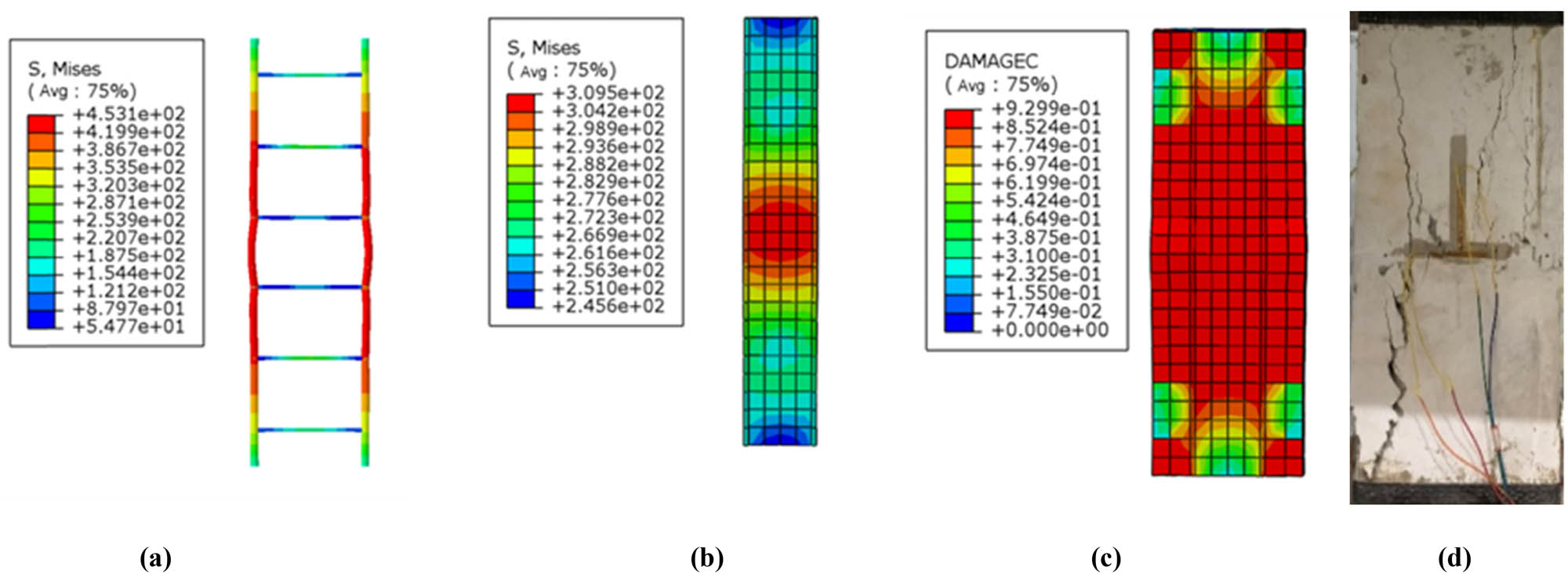
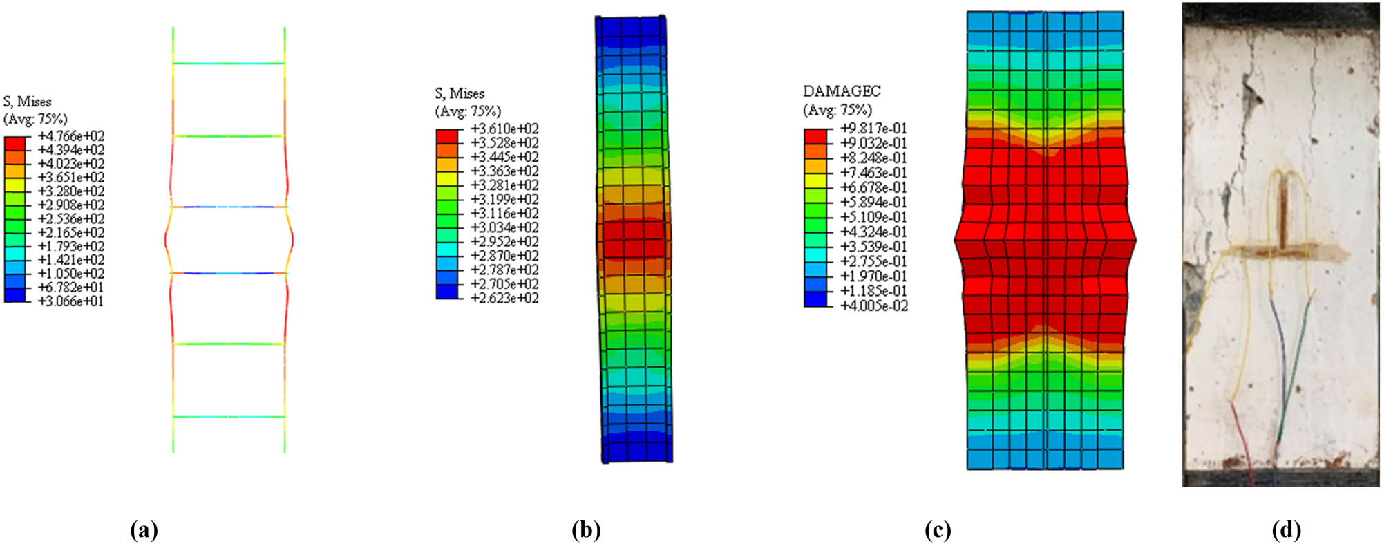
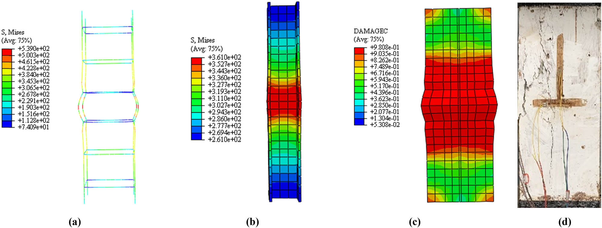
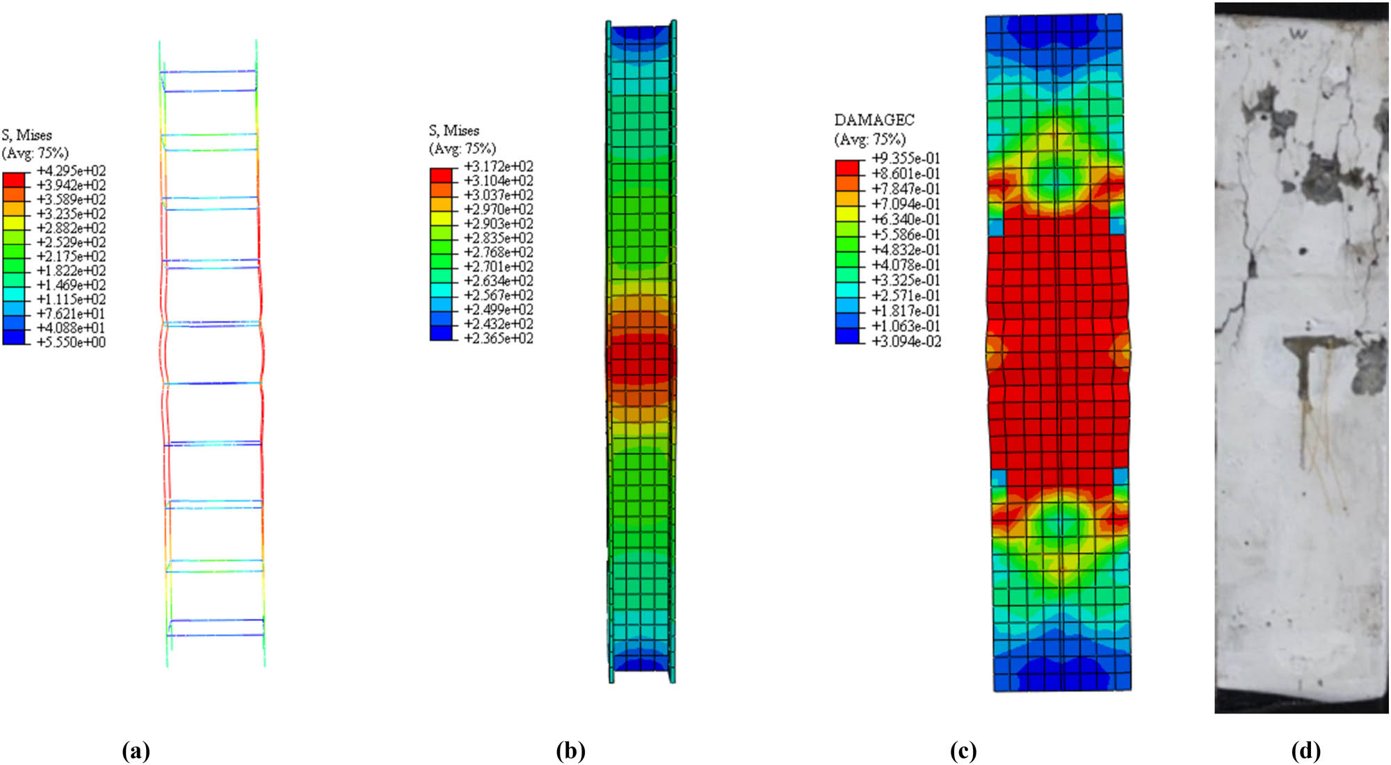
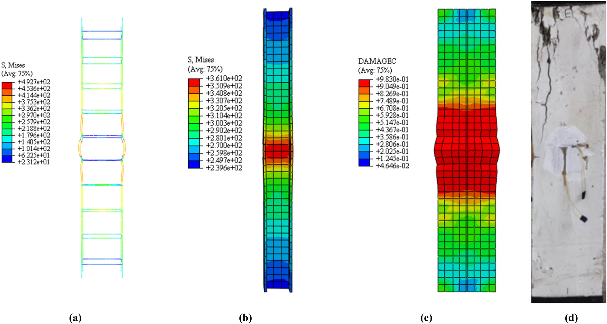
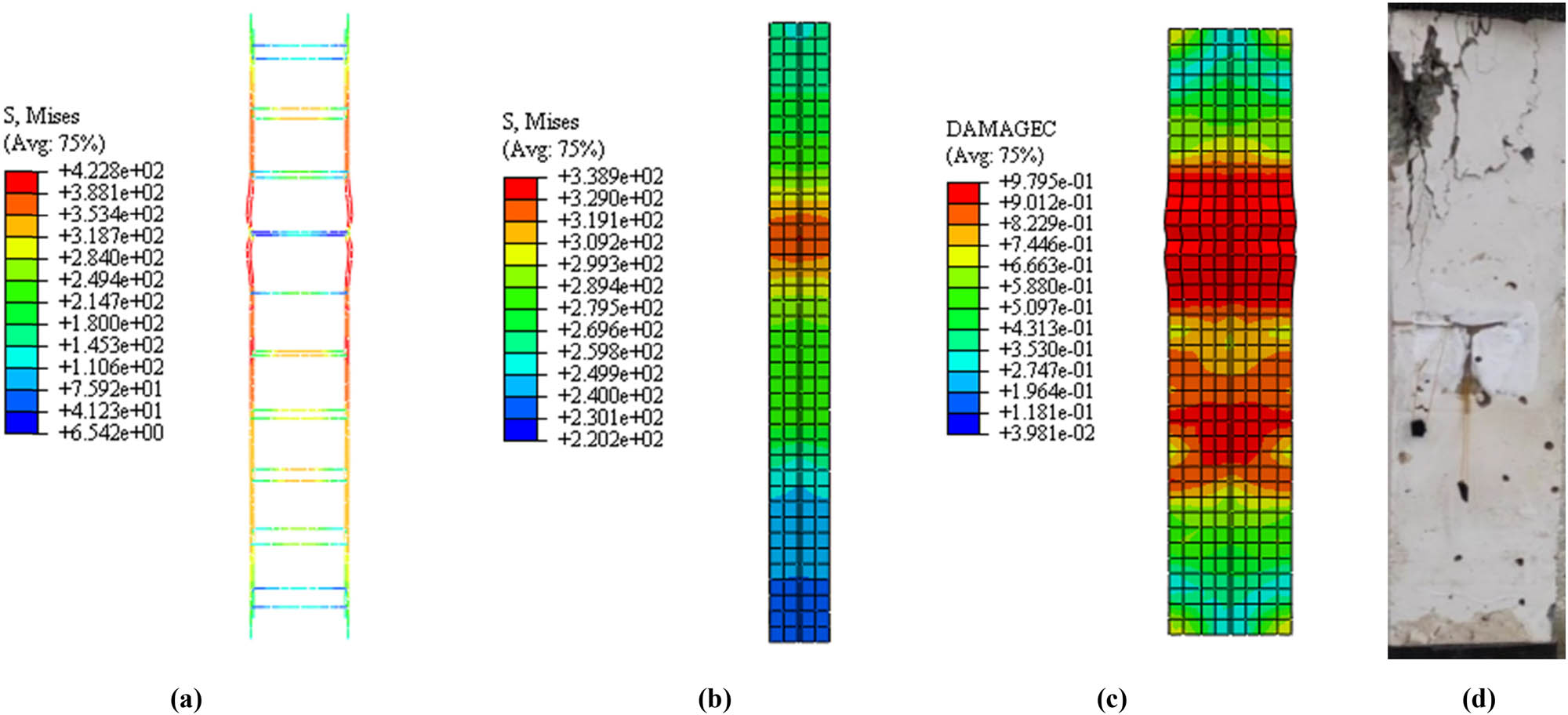
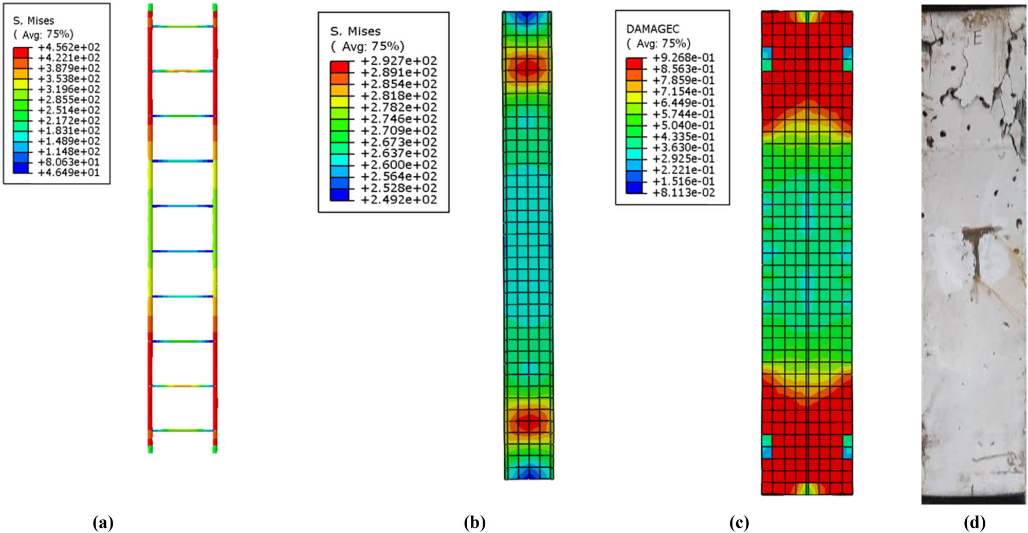
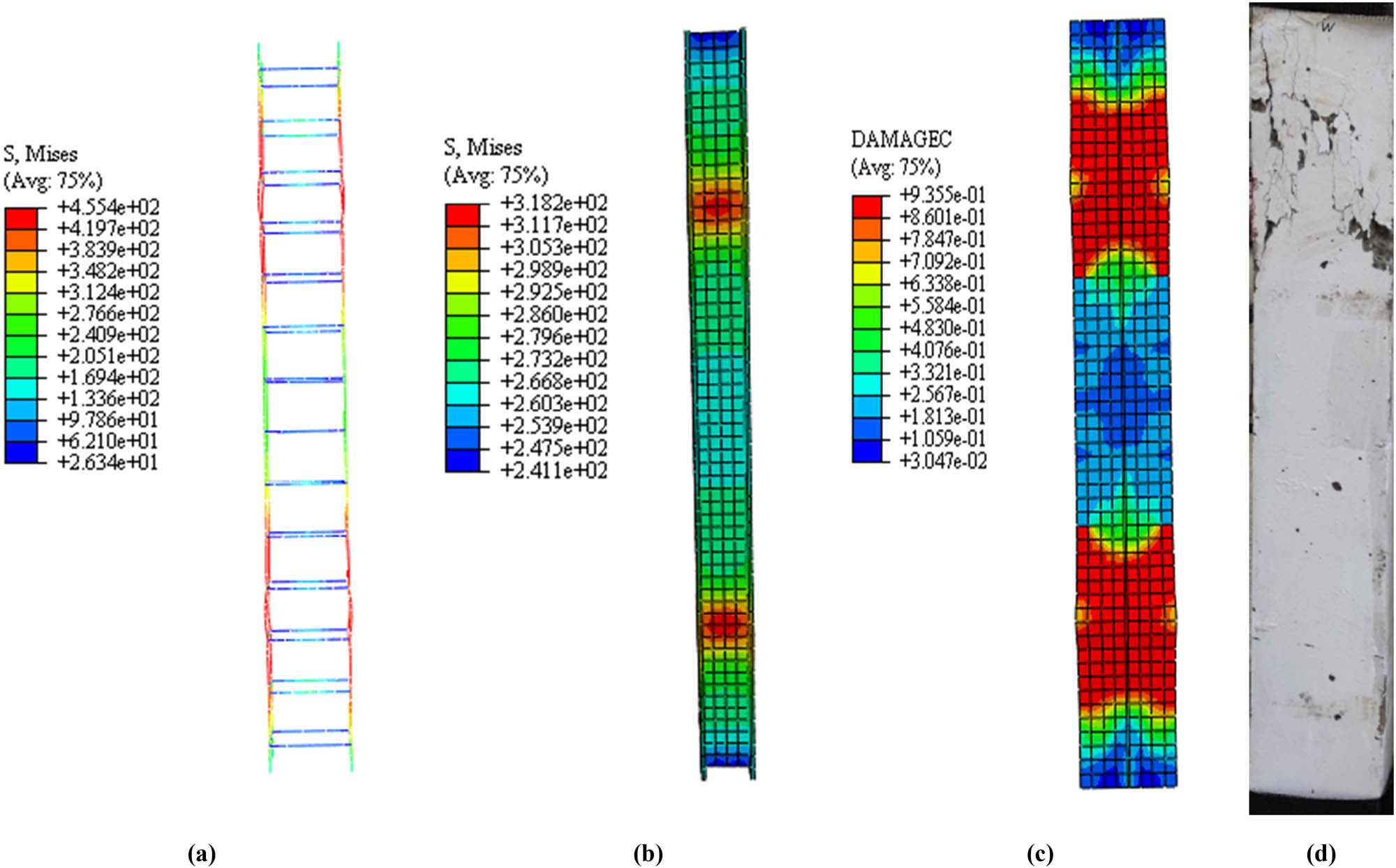
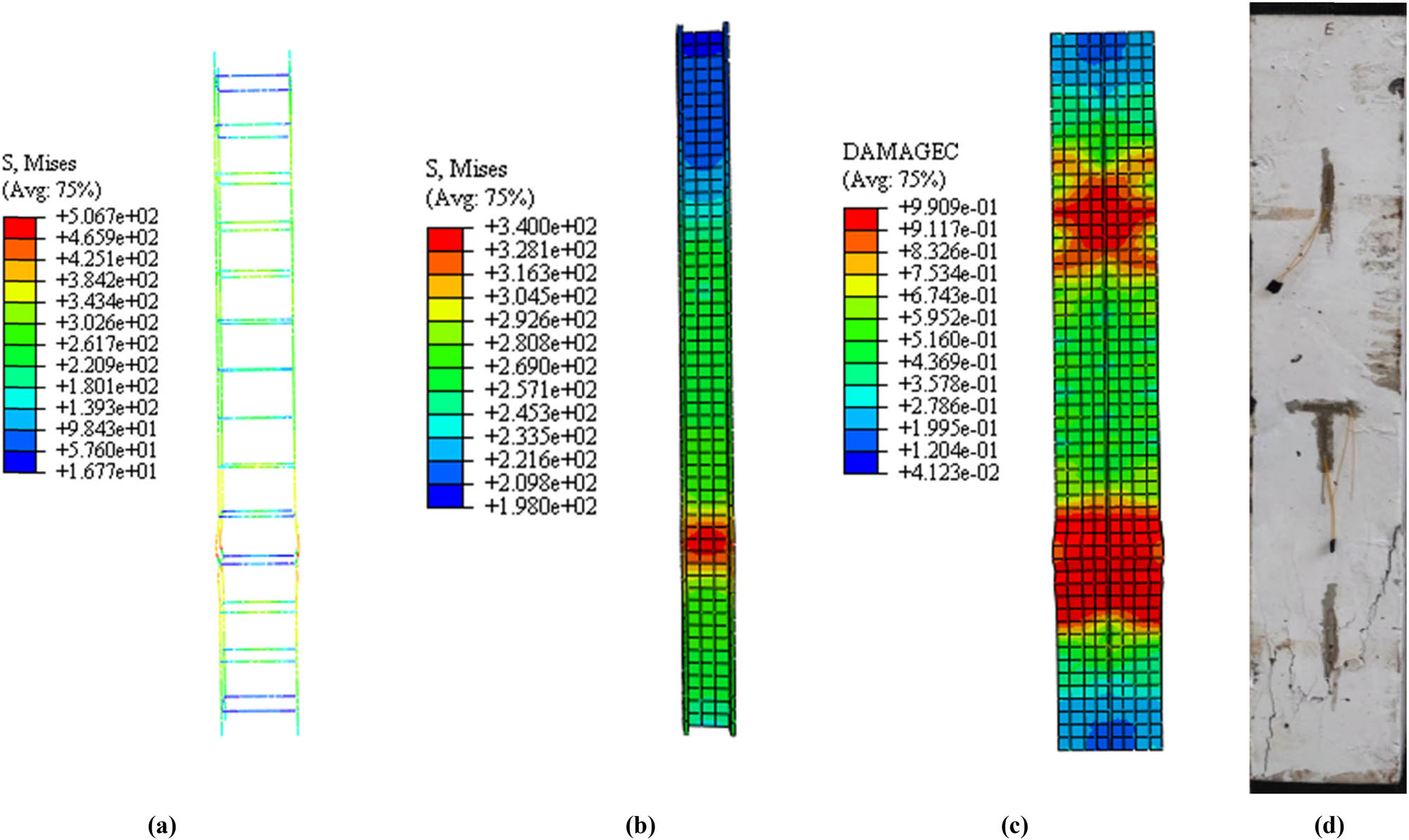
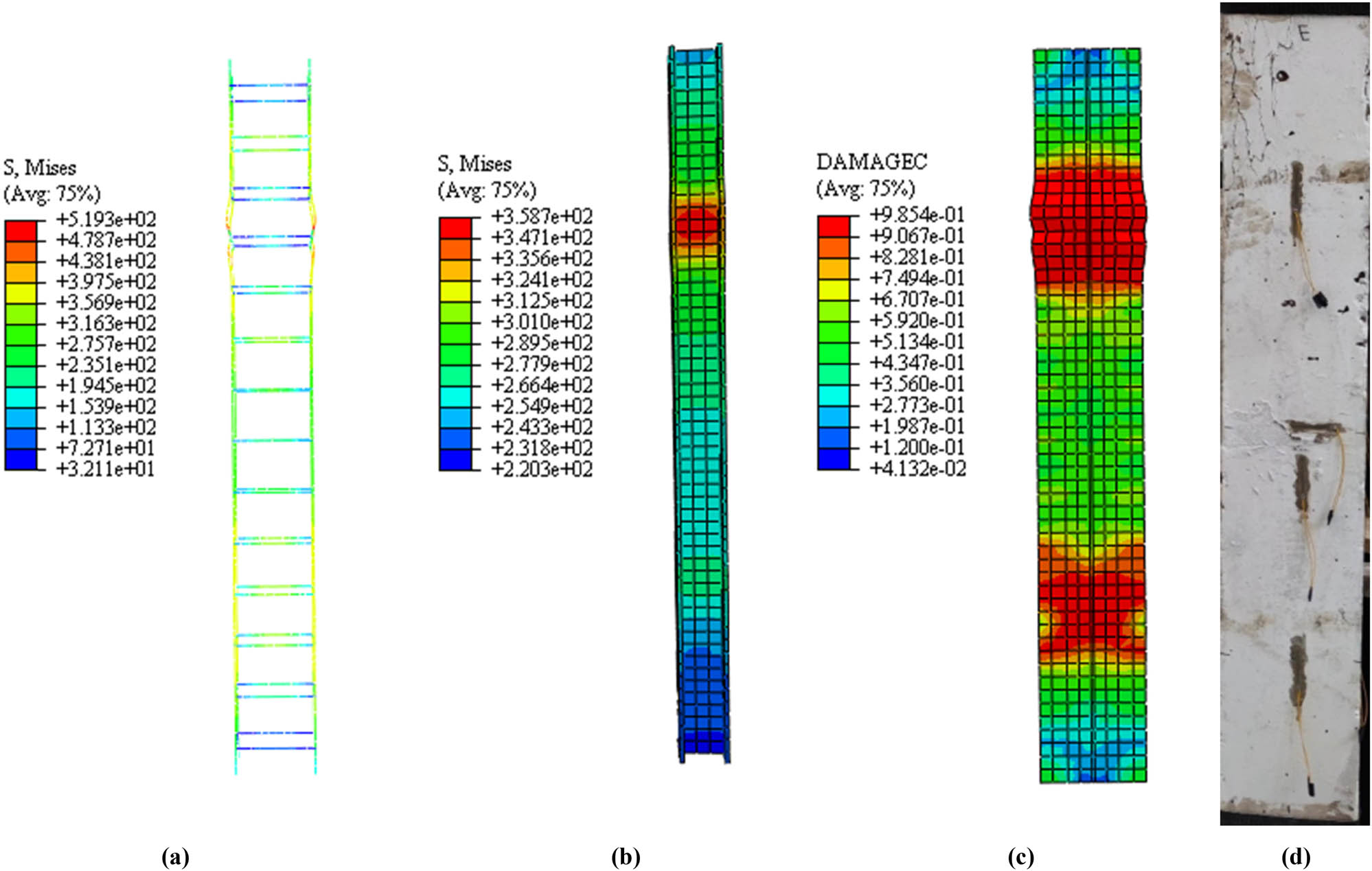
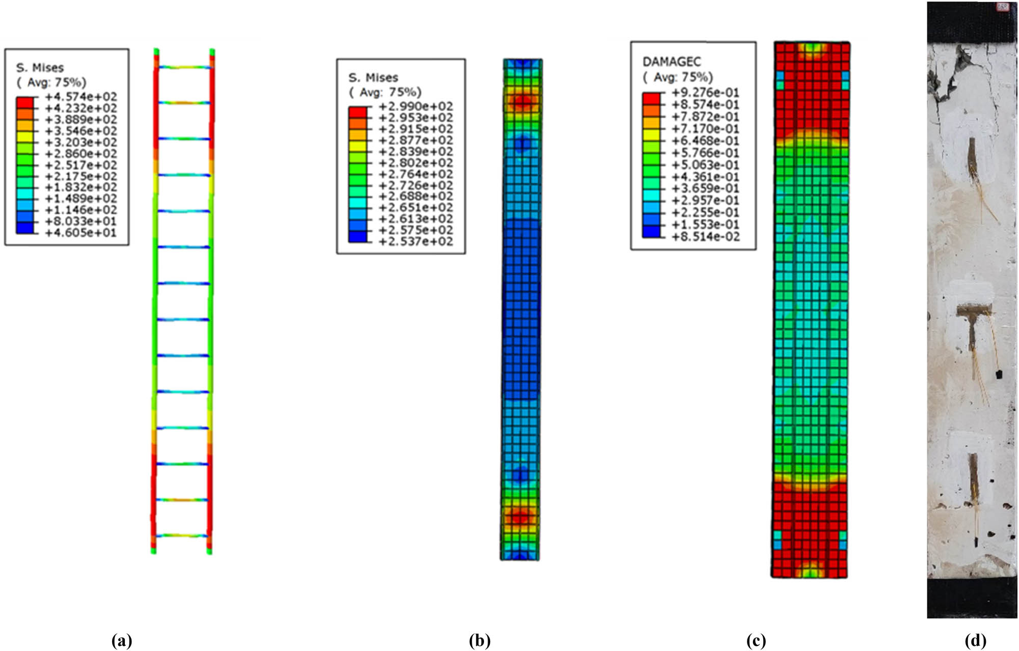
Figures 21–32 show the stress virtual reality and concrete damage virtual reality of the finite element model of corroded SRC columns. The failure mode of SRC columns with a length of 0.6 m is mainly due to the bending of longitudinal steel bars and the middle section steel. In addition, the virtual reality of concrete compression damage indicates that the concrete in the middle of the SRC column shrinks and protrudes outward, which is consistent with the experimental failure mode. When the rust rate is relatively low for the failure mode of SRC columns with a length of 1.0 m, it is similar to that of SRC columns with a length of 0.6 m. As the rust rate increases, the failure mainly develops toward both ends of the longitudinal steel bars and section steel. The concrete compression damage virtual reality shows the same damage mode as longitudinal steel reinforcement and section steel failure mode. The failure gradually develops toward both ends as the rust rate increases. There is a slight difference between the finite element method and the experiment here, possibly due to the uneven corrosion during the experimental process. The failure mode of a 1.4 m corroded SRC column shows that the plastic deformation of longitudinal steel bars and profiles is mainly concentrated near the upper and lower ends of the SRC column during specimen failure. According to the concrete compression damage virtual reality, the upper and lower ends of the SRC column collapse and bulge outward, which is consistent with the experimental failure mode.
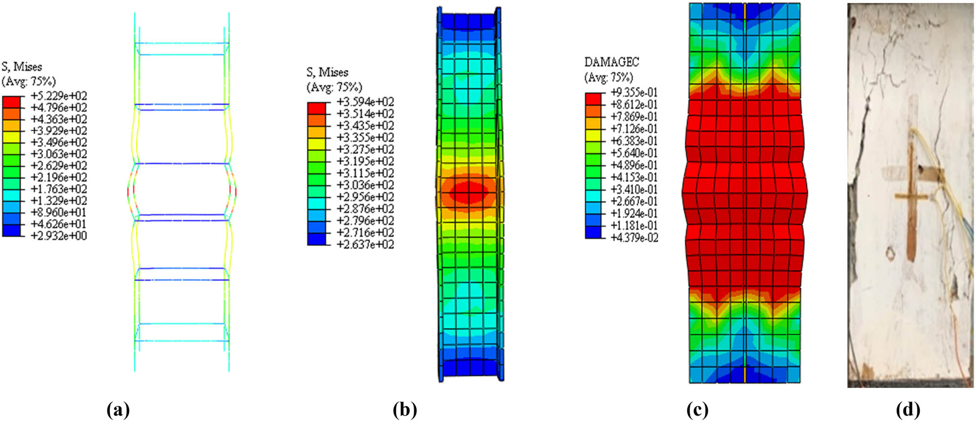
Finite element analysis results of D0-CL0-EC0-L0.6. (a) Virtual reality of stress distribution in reinforcement. (b) Virtual reality of stress distribution in section steel. (c) Virtual reality of concrete compression damage. (d) Failure mode.
Finite element analysis results of D9-CL2.0-EC5.0-L0.6. (a) Virtual reality of stress distribution in reinforcement. (b) Virtual reality of stress distribution in section steel. (c) Virtual reality of concrete compression damage. (d) Failure mode.
Finite element analysis results of D9-CL3.5-EC5.0-L0.6. (a) Virtual reality of stress distribution in reinforcement. (b) Virtual reality of stress distribution in section steel. (c) Virtual reality of concrete compression damage. (d) Failure mode.
Finite element analysis results of D9-CL5.0-EC5.0-L0.6. (a) Virtual reality of stress distribution in reinforcement. (b) Virtual reality of stress distribution in section steel. (c) Virtual reality of concrete compression damage. (d) Failure mode.
Finite element analysis results of D0-CL0-EC0-L1.0. (a) Virtual reality of stress distribution in reinforcement. (b) Virtual reality of stress distribution in section steel. (c) Virtual reality of concrete compression damage. (d) Failure mode.
Finite element analysis results of D6-CL3.5-EC5.0-L1.0. (a) Virtual reality of stress distribution in reinforcement. (b) Virtual reality of stress distribution in section steel. (c) Virtual reality of concrete compression damage. (d) Failure mode.
Finite element analysis results of D9-CL3.5-EC5.0-L1.0. (a) Virtual reality of stress distribution in reinforcement. (b) Virtual reality of stress distribution in section steel. (c) Virtual reality of concrete compression damage. (d) Failure mode.
Finite element analysis results of D12-CL3.5-EC5.0-L1.0. (a) Virtual reality of stress distribution in reinforcement. (b) Virtual reality of stress distribution in section steel. (c) Virtual reality of concrete compression damage. (d) Failure mode.
Finite element analysis results of D0-CL0-EC0-L1.4. (a) Virtual reality of stress distribution in reinforcement. (b) Virtual reality of stress distribution in section steel. (c) Virtual reality of concrete compression damage. (d) Failure mode.
Finite element analysis results of D9-CL3.5-EC2.0-L1.4. (a) Virtual reality of stress distribution in reinforcement. (b) Virtual reality of stress distribution in section steel. (c) Virtual reality of concrete compression damage. (d) Failure mode.
Finite element analysis results of D9-CL3.5-EC5.0-L1.4. (a) Virtual reality of stress distribution in reinforcement. (b) Virtual reality of stress distribution in section steel. (c) Virtual reality of concrete compression damage. (d) Failure mode.
Finite element analysis results of D9-CL3.5-EC8.0-L1.4. (a) Virtual reality of stress distribution in reinforcement. (b) Virtual reality of stress distribution in section steel. (c) Virtual reality of concrete compression damage. (d) Failure mode.
Overall, the comparison between finite element analysis and experiments is highly consistent and has a specific reference value. From the finite element analysis and experimental results, it can be concluded that the failure of corroded SRC columns under axial compression is mainly due to strength failure. For the 0.6 m SRC column, concrete collapse and steel yield are mainly distributed in the middle of the column. The damage area of the 1.4 m SRC column is mainly concentrated at the upper and lower ends of the SRC column. The failure mode of the 1.0 m SRC column is between the two. The main manifestations of the damaged area are local concrete crushing, longitudinal splitting of concrete, yielding of H-shaped steel flanges, yielding of longitudinal reinforcement, and hoop reinforcement.
3 Parameter analysis
3.1 Establishment of parameter analysis model
In Table 6, the specimen is labeled with “SRC-ρ-L,” where ρ indicates the rust rate of the section steel and L represents the calculated height of the SRC column. Among them, the ultimate bearing capacity, ductility coefficient, and axial compression stiffness are critical indicators to measure the axial compression performance of SRC that need special attention.
where N y and Δ y are yield load and corresponding displacement, respectively.
where
Calculation results of parameter analysis
| Specimen number | L (m) | λ | ρ 1 (%) | ρ 2 (%) | ρ 3 (%) | N u (kN) | μ | K (kN/mm) |
|---|---|---|---|---|---|---|---|---|
| SRC-0-0.6 | 0.6 | 11.12 | 0 | 0 | 0 | 2316.75 | 2.447 | 2,007 |
| SRC-0-0.6 | 11.32 | 5 | 7.5 | 4.05 | 2201.65 | 2.405 | 1,917 | |
| SRC-0-0.6 | 11.42 | 10 | 15 | 8.1 | 1924.65 | 2.310 | 1,657 | |
| SRC-15-0.6 | 11.51 | 15 | 22.5 | 12.15 | 1606.34 | 2.269 | 1,452 | |
| SRC-15-0.6 | 11.57 | 20 | 30 | 16.2 | 1604.68 | 2.267 | 1,450 | |
| SRC-15-0.6 | 11.60 | 25 | 37.5 | 20.25 | 1557.51 | 2.259 | 1,404 | |
| SRC-30-0.6 | 11.63 | 30 | 45 | 24.3 | 1553.07 | 2.258 | 1,401 | |
| SRC-30-0.6 | 11.64 | 35 | 52.5 | 28.35 | 1544.84 | 2.243 | 1,389 | |
| SRC-30-0.6 | 11.65 | 40 | 60 | 32.4 | 1314.10 | 2.187 | 1,157 | |
| SRC-45-0.6 | 11.67 | 45 | 67.5 | 36.45 | 1290.35 | 2.166 | 1,134 | |
| SRC-45-0.6 | 11.70 | 50 | 75 | 40.5 | 1273.64 | 2.147 | 1,086 | |
| SRC-45-0.6 | 11.75 | 55 | 82.5 | 44.55 | 1254.64 | 2.134 | 1,064 | |
| SRC-60-0.6 | 11.66 | 60 | 90 | 48.6 | 1244.27 | 2.112 | 1,056 | |
| SRC-0-0.8 | 0.8 | 15.14 | 0 | 0 | 0 | 2302.47 | 2.405 | 1,746 |
| SRC-0-0.8 | 15.28 | 5 | 7.5 | 4.05 | 2094.81 | 2.363 | 1,636 | |
| SRC-0- 0.8 | 15.37 | 10 | 15 | 8.1 | 1917.43 | 2.267 | 1,317 | |
| SRC-0-0.8 | 15.52 | 15 | 22.5 | 12.15 | 1602.61 | 2.212 | 1,108 | |
| SRC-0-0.8 | 15.58 | 20 | 30 | 16.2 | 1597.57 | 2.207 | 1,102 | |
| SRC-0-0.8 | 15.61 | 25 | 37.5 | 20.25 | 1547.94 | 2.201 | 1,054 | |
| SRC-0-0.8 | 15.65 | 30 | 45 | 24.3 | 1544.23 | 2.195 | 1,050 | |
| SRC-0-0.8 | 15.69 | 35 | 52.5 | 28.35 | 1539.89 | 2.183 | 1,035 | |
| SRC-0-0.8 | 15.72 | 40 | 60 | 32.4 | 1312.56 | 2.124 | 1,005 | |
| SRC-0-0.8 | 15.69 | 45 | 67.5 | 36.45 | 1258.26 | 2.101 | 985 | |
| SRC-0-0.8 | 15.75 | 50 | 75 | 40.5 | 1247.15 | 2.084 | 970 | |
| SRC-0-0.8 | 15.79 | 55 | 82.5 | 44.55 | 1223.44 | 2.071 | 956 | |
| SRC-0-0.8 | 15.81 | 60 | 90 | 48.6 | 1098.82 | 1.958 | 954 | |
| SRC-0-1.0 | 1.0 | 18.54 | 0 | 0 | 0 | 2279.59 | 2.361 | 1,286 |
| SRC-0-1.0 | 18.79 | 5 | 7.5 | 4.05 | 2064.17 | 2.335 | 1,152 | |
| SRC-0-1.0 | 18.94 | 10 | 15 | 8.1 | 1817.56 | 2.226 | 886 | |
| SRC-15-1.0 | 19.17 | 15 | 22.5 | 12.15 | 1615.64 | 2.182 | 659 | |
| SRC-15-1.0 | 19.20 | 20 | 30 | 16.2 | 1594.79 | 2.180 | 653 | |
| SRC-15-1.0 | 19.29 | 25 | 37.5 | 20.25 | 1577.79 | 2.171 | 601 | |
| SRC-30-1.0 | 19.38 | 30 | 45 | 24.3 | 1564.49 | 2.168 | 597 | |
| SRC-30-1.0 | 19.42 | 35 | 52.5 | 28.35 | 1557.19 | 2.153 | 584 | |
| SRC-30-1.0 | 19.45 | 40 | 60 | 32.4 | 1345.84 | 2.101 | 559 | |
| SRC-45-1.0 | 19.44 | 45 | 67.5 | 36.45 | 1267.73 | 2.085 | 532 | |
| SRC-45-1.0 | 19.41 | 50 | 75 | 40.5 | 1257.79 | 2.063 | 521 | |
| SRC-45-1.0 | 19.44 | 55 | 82.5 | 44.55 | 1179.13 | 2.051 | 495 | |
| SRC-60-1.0 | 19.38 | 60 | 90 | 48.6 | 1169.97 | 2.028 | 491 | |
| SRC-60-1.2 | 1.2 | 22.56 | 0 | 0 | 0 | 2231.74 | 2.335 | 1,059 |
| SRC-60-1.2 | 22.84 | 5 | 7.5 | 4.05 | 2111.89 | 2.292 | 945 | |
| SRC-60-1.2 | 22.96 | 10 | 15 | 8.1 | 1857.38 | 2.208 | 621 | |
| SRC-60-1.2 | 23.07 | 15 | 22.5 | 12.15 | 1530.56 | 2.163 | 615 | |
| SRC-60-1.2 | 23.12 | 20 | 30 | 16.2 | 1525.84 | 2.161 | 612 | |
| SRC-60-1.2 | 23.15 | 25 | 37.5 | 20.25 | 1472.76 | 2.152 | 569 | |
| SRC-60-1.2 | 23.04 | 30 | 45 | 24.3 | 1467.68 | 2.150 | 567 | |
| SRC-60-1.2 | 23.15 | 35 | 52.5 | 28.35 | 1454.75 | 2.141 | 552 | |
| SRC-60-1.2 | 23.20 | 40 | 60 | 32.4 | 1237.34 | 2.056 | 524 | |
| SRC-60-1.2 | 23.24 | 45 | 67.5 | 36.45 | 1224.67 | 2.031 | 501 | |
| SRC-60-1.2 | 23.55 | 50 | 75 | 40.5 | 1201.65 | 2.014 | 486 | |
| SRC-60-1.2 | 24.10 | 55 | 82.5 | 44.55 | 1181.15 | 2.008 | 476 | |
| SRC-60-1.2 | 24.14 | 60 | 90 | 48.6 | 1177.52 | 1.971 | 474 | |
| SRC-60-1.4 | 1.4 | 25.95 | 0 | 0 | 0 | 2201.55 | 2.285 | 986 |
| SRC-60-1.4 | 26.10 | 5 | 7.5 | 4.05 | 2041.53 | 2.262 | 874 | |
| SRC-60-1.4 | 26.26 | 10 | 15 | 8.1 | 1756.17 | 2.171 | 553 | |
| SRC-60-1.4 | 26.32 | 15 | 22.5 | 12.15 | 1427.89 | 2.122 | 324 | |
| SRC-60-1.4 | 26.32 | 20 | 30 | 16.2 | 1419.45 | 2.120 | 321 | |
| SRC-60-1.4 | 26.32 | 25 | 37.5 | 20.25 | 1381.47 | 2.115 | 201 | |
| SRC-60-1.4 | 26.35 | 30 | 45 | 24.3 | 1376.27 | 2.112 | 195 | |
| SRC-60-1.4 | 26.35 | 35 | 52.5 | 28.35 | 1364.15 | 2.101 | 193 | |
| SRC-60-1.4 | 26.35 | 40 | 60 | 32.4 | 1197.20 | 2.045 | 185 | |
| SRC-60-1.4 | 26.39 | 45 | 67.5 | 36.45 | 1177.78 | 2.027 | 163 | |
| SRC-60-1.4 | 26.39 | 50 | 75 | 40.5 | 1157.16 | 2.001 | 142 | |
| SRC-60-1.4 | 26.39 | 55 | 82.5 | 44.55 | 1141.64 | 1.994 | 131 | |
| SRC-60-1.4 | 26.35 | 60 | 90 | 48.6 | 1104.59 | 1.984 | 128 |
Note: ρ 1, ρ 2, and ρ 3 are corrosion rates of section steel, stirrups, and longitudinal bars, respectively.
To understand the effect of slenderness ratio and rust rate on the performance of SRC long columns under axial compression, the influence coefficients
Among them, coefficients
Fitting function of the impact coefficient of slenderness rate on the axial compression performance of long columns in SRC
| N uλ (kN) | μ λ | K λ (kN/mm) |
|---|---|---|
|
|
|
|
|
|
|
|
3.2 Effect of slenderness ratio on axial compression performance of long columns in SRC
Figure 33 shows a curve that reflects the relationship between the slenderness ratio and the axial compression performance of SRC middle-length columns. Their ultimate bearing capacity and displacement ductility coefficient are almost linearly and positively related to the slenderness ratio for non-corroded SRC middle-length columns. However, the axial compression stiffness decreases massively as the slenderness rate gradually rises. More specifically, when the slenderness rate grows to 25.95, the axial compression stiffness decreases by 50.9%, while the ultimate bearing capacity and displacement ductility coefficient decrease by 5.0 and 6.6%, respectively. In summary, a higher slenderness ratio significantly influences the axial compressive stiffness of long columns in SRC. However, its ultimate bearing capacity and displacement ductility coefficient have no significant drop.
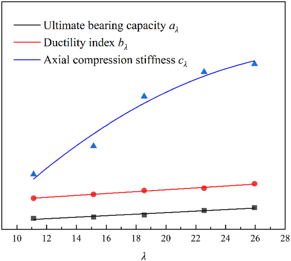
Influence curve of slenderness ratio on axial compression performance of long columns in SRC.
Based on the results shown in Figure 33 and the mathematical calculation model in Table 7, the ultimate compressive strength
3.3 The influence of rust rate on the axial compression performance of long columns in SRC
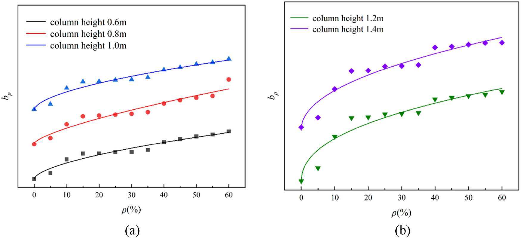
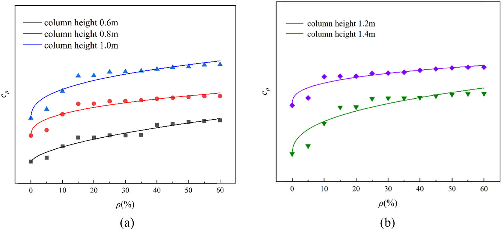
Figures 34–36 show the degradation curve of rust rate, the ultimate bearing capacity, displacement ductility coefficient, and axial compression stiffness of SRC medium-long columns under the same column height conditions. The conclusions are as follows:
As the rust rate rises from 0 to 60%, the axial compression performance (ultimate bearing capacity, displacement ductility coefficient, and axial compression stiffness) of long columns in SRC significantly drops.
At the same corrosion rate, the degradation coefficient of long SRC columns with a slenderness ratio of 25.95 is greater than that of long SRC columns at 11.12, 15.14, 18.54, and 22.56 ratios. Therefore, a larger slenderness ratio leads to a more substantial degradation effect of corrosion.
When the rust rate increased from 0 to 15, 30, 45, and 60%, the average ultimate bearing capacity of long columns in SRC decreased by 22.3, 33.8, 45.1, and 48.9%, respectively. This is because the corrosion reduces the strength of the concrete protective layer and accelerates performance degradation of the cross-sectional area of SRC columns. When the corrosion degree reaches 45%, the decline of ultimate bearing capacity tends to slow down and reach a stable platform. When this degree reaches 60%, the concrete protective layer is broken.
When the rust rate increased from 0 to 15, 30, 45, and 60%, the average displacement ductility coefficient of the long column in SRC decreased by 7.7, 8.3, 12.3, and 15.3%, respectively. The decrease in displacement ductility coefficient can be explained by the corrosion in the steel section, leading to local stress concentration and destabilizing the buckling, leading to higher deformation capacity of the long column in SRC.
When the rust rate increased from 0 to 15, 30, 45, and 60%, the average axial compression stiffness of the long columns in SRC decreased by 44.4, 50.1, 56.4, and 59.4%, respectively, which is because corrosion leads to the cracking of concrete surfaces. It is noted that the axial compression stiffness of the long columns in SRC decreased sharply at the early stage of corrosion but slowed down later. When the rust rate is about 45%, the impact on the axial compression stiffness of the long columns in SRC reaches its maximum.
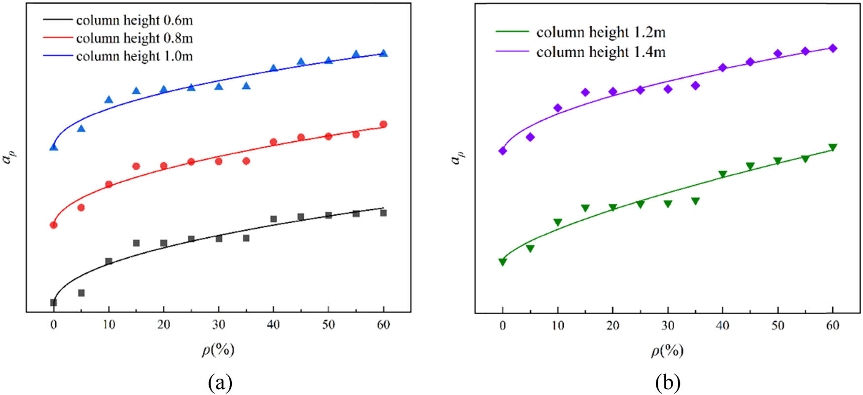
Deterioration curve of rust rate on the ultimate bearing capacity of long columns in SRC. (a) Coefficient
Degradation curve of rust rate on the displacement ductility coefficient of long columns in SRC. (a) Coefficient
Degradation curve of axial compression stiffness of long columns in SRC by rust rate. (a) Coefficient
According to Figures 34–36 and the mathematical calculation model in Table 8, the ultimate compressive strength
Fitting function of deterioration coefficient of rust rate on axial compression performance of long columns in SRC
| N uρ (kN) | μ ρ | K ρ (kN/mm) | |
|---|---|---|---|
| L0.6 |
|
|
|
|
|
|
|
|
| L0.8 |
|
|
|
|
|
|
|
|
| L1.0 |
|
|
|
|
|
|
|
|
| L1.2 |
|
|
|
|
|
|
|
|
| L1.4 |
|
|
|
|
|
|
|
4 Calculation formula for bearing capacity of SRC middle-length columns considering corrosion effects
4.1 Reduction factors of ultimate bearing capacity
Due to the previous parameter analysis only considering the influence of slenderness ratio and rust rate, and the axial compression performance of SRC separately, a calculation formula was established in order to more intuitively express the coupling effect of slenderness ratio and rust rate, the ultimate bearing capacity of long columns in SRC.
As the part of section steel only accounts for a small part in the entire section of SRC columns, the stable bearing capacity of SRC short columns can be calculated by an approach similar to that of RC axial compression units, as shown in Eq. (38).
where A
1 is the concrete area of the unconstrained area, A
2 is the concrete area in the confinement area of the stirrup, A
3 is the concrete area of the composite constraint area, A
s is the sum of the cross-sectional areas of the longitudinal reinforcement, A
a is the cross-sectional area of the section steel,
When corrosion happens in the component and slenderness ratio changes, SRC columns’ axial compressive ultimate bearing capacity will correspondingly decrease. Therefore, a reduction coefficient K is introduced to describe how ultimate bearing capacity decreases. The reduction coefficient is a functional expression that includes the component’s slenderness and corrosion rates. Considering the deterioration effect, the axial compressive ultimate bearing capacity of corroded SRC columns can be calculated by the Eqs (39)–(42).
Regression fitting was performed on the data, and the specific expression was obtained as Eqs (41) and (42). The fitting surface graph is shown in Figure 37.
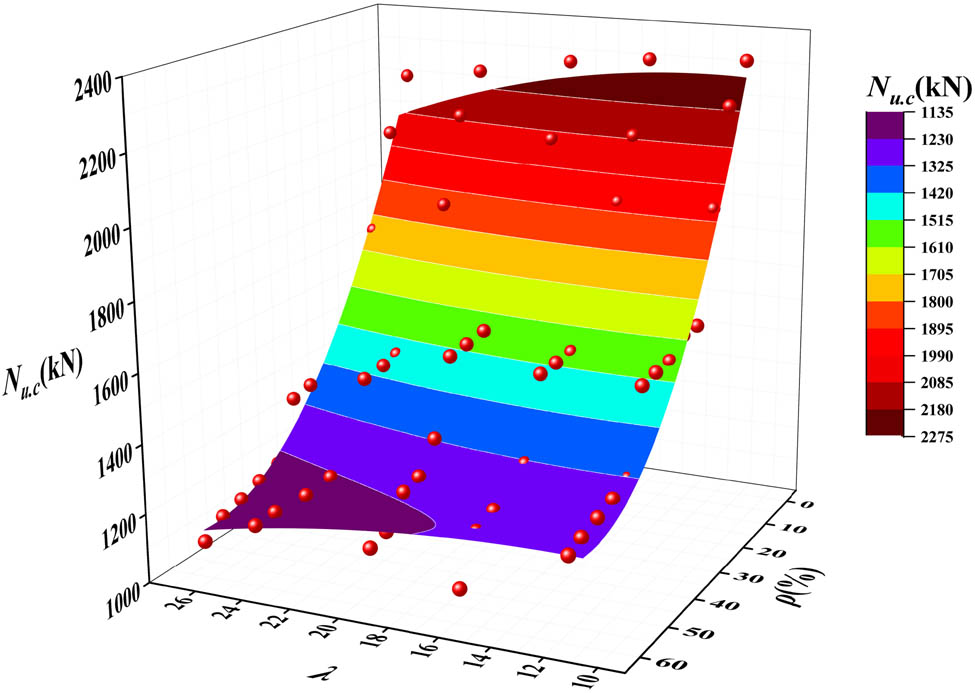
Fitted surface of λ and ρ influence regularity.
4.2 Regression formula test
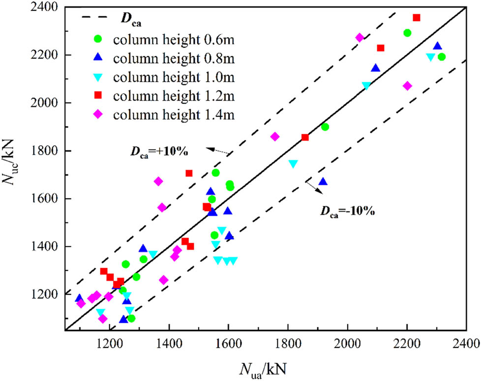
To verify and ensure a more accurate established ultimate bearing capacity formula, Eq. (43) can be adapted to predict the current results. D ca represents the deviation between the predicted ultimate bearing capacity N uc and the finite element results in N ua.
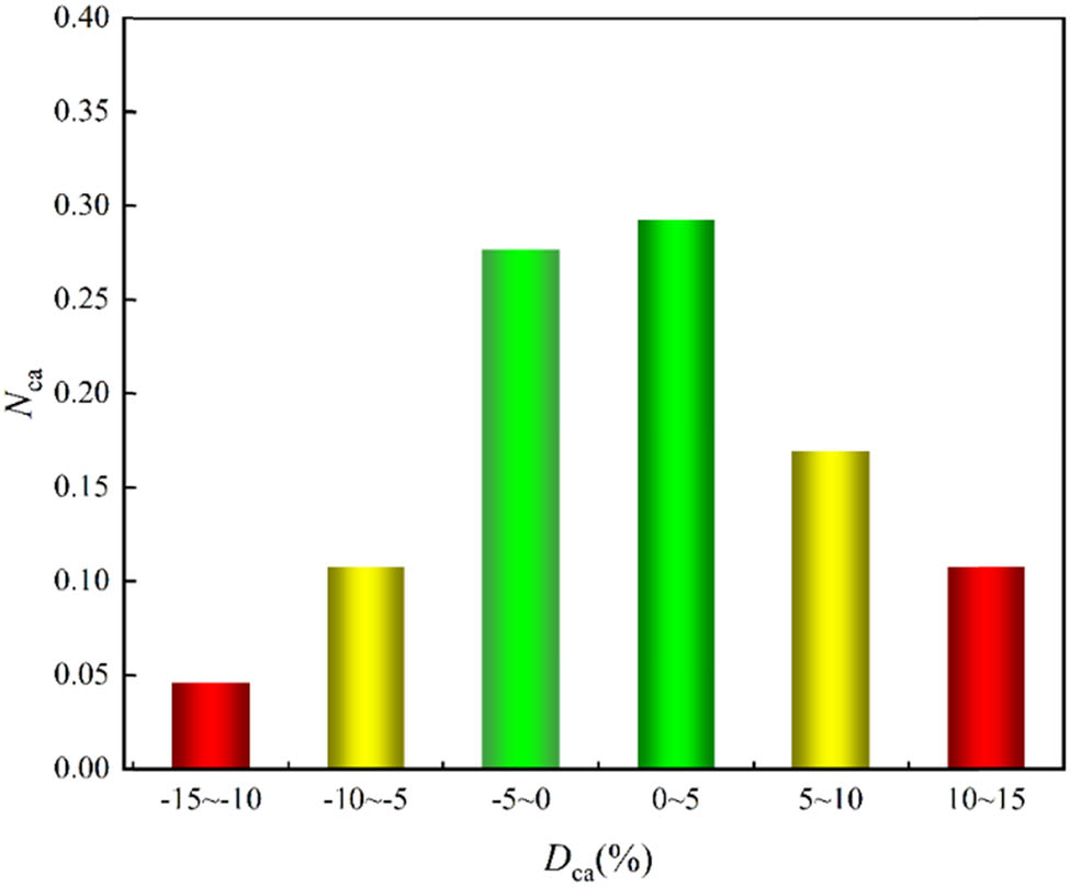
According to Figure 38, the deviation in corroded SRC is mostly within ±10%. Moreover, in Figure 38, N ca is used to quantitatively represent the percentage of samples falling within a given deviation range to the number of D ca samples. From this figure, samples exceeding ±10% account for about 15% of the total, indicating that most prediction results can match finite element data well. Overall, the regression formula can be considered efficient to achieve relatively accurate predictions.
where n i represents the number of SRC long-column specimens within the specific deviation range given in Figure 39, and n represents the total amount of specimens.
Range of deviations in the prediction model.
Distribution of bias in the prediction model.
5 Conclusion
This study established a numerical analysis model for corroded SRC middle-length columns. The effects of slenderness ratio and rust rate on its axial compression performance were studied and the conclusion is as follows:
A bond–slip constitutive relationship between steel and concrete was established, and it was found that when the rust rate was low, the bond stress of SRC columns would be increased compared to those without corrosion. When the rust rate exceeds 15%, the ultimate and residual bonding stress will significantly decrease.
When the slenderness ratio increases to 25.95, the axial compressive stiffness decreases by 50.9%, while the ultimate bearing capacity and displacement ductility coefficient decrease by 5.0 and 6.6%, respectively. A higher aspect ratio significantly affects the axial compressive stiffness of long columns in SRC. However, its ultimate bearing capacity and displacement ductility coefficient did not show a significant decrease.
When the rust rate increased from 0 to 15, 30, 45, and 60%, the average displacement ductility coefficient of long columns in SRC decreased by 7.7, 8.3, 12.3, and 15.3%, respectively. The reason is that corrosion reduces the cross-sectional area of the steel, resulting in local stress concentration and unstable buckling.
The axial compressive stiffness of long columns in SRC decreases sharply in the early stage of corrosion but slows down slightly in the later stage. When the rust rate is about 45%, the axial compressive stiffness of the long column in SRC is affected to the maximum value.
The reduction coefficient K related to the slenderness ratio and rust rate is proposed to represent the effect of corrosion on the ultimate bearing capacity of SRC columns. Considering the effect of corrosion, the established formulas for calculating the ultimate bearing capacity of SRC columns have good accuracy.
In summary, this study established a numerical analysis model for SRC mid-length columns considering corrosion effects and studied the effects of slenderness ratio and rust rate on the axial compression performance of SRC mid-length columns. The research results contribute to solving the corrosion problem of long columns in SRC and provide a reference for the application and design of long columns in SRC. However, the main content of this study is a simulation study of corroded SRC columns, which needs stronger persuasiveness.
Acknowledgments
The authors gratefully acknowledge the support of National Natural Science Foundation of China (No. 52078138), Guiding Project of Fujian Province (No. 2021Y0003), Science and Technology Planning Project of Fuzhou (No. 2021-Y-083), and Fifth Batch of Science and Technology Plan Project of Housing and Urban-Rural Construction Industry of Fujian Province in 2022 (No. 2022-K-298), and Fujian Province housing and urban and rural construction industry 2023 second batch of science and technology plan projects (No. 2023-K-71).
-
Funding information: This study was funded by the National Natural Science Foundation of China (No. 52078138), the Guiding Project of Fujian Province (No. 2021Y0003), the Science and Technology Planning Project of Fuzhou (No. 2021-Y-083), and Fifth Batch of Science and Technology Plan Project of Housing and Urban-Rural Construction Industry of Fujian Province in 2022 (No. 2022-K-298), and Fujian Province housing and urban and rural construction industry 2023 second batch of science and technology plan projects (No. 2023-K-71).
-
Author contributions: All authors have accepted responsibility for the entire content of this manuscript and approved its submission.
-
Conflict of interest: The authors state no conflict of interest.
References
[1] Sonnenschein, R., K. Gajdosova, and S. Gramblicka. Comparison of composite, steel and reinforced concrete columns. IOP Conference Series: Materials Science and Engineering, Vol. 960, No. 3, 2020, id. 032093(6pp).10.1088/1757-899X/960/3/032093Suche in Google Scholar
[2] Chanchan, Z., W. Guangyong, and L. I. Yinqing. Fire performance of axially restrained steel reinforced concrete columns. Journal of Building Structures, Vol. 43, No. 8, 2022, id. 154.Suche in Google Scholar
[3] Medall, D., C. Ibáñez, V. Albero, A. Espinós, and M. L. Romero. Experimental residual capacity of steel-reinforced concrete-filled steel tubular stub columns after fire exposure. Thin-Walled Structures, Vol. 189, 2023, id. 110900.10.1016/j.tws.2023.110900Suche in Google Scholar
[4] Zhao, X., F. Wen, T. M. Chan, and S. Cao. Theoretical stress–strain model for concrete in steel-reinforced concrete columns. Journal of Structural Engineering, Vol. 145, No. 4, 2019, id. 04019009.10.1061/(ASCE)ST.1943-541X.0002289Suche in Google Scholar
[5] Chu, L., Y. Tian, D. Li, Y. He, and H. Feng. Shear behavior of steel reinforced concrete column-steel beam joints with or without reinforced concrete slab. Journal of Building Engineering, Vol. 35, 2021, id. 102063.10.1016/j.jobe.2020.102063Suche in Google Scholar
[6] Wang, J., X. Yi, Q. Liu, and X. Fang. Seismic performance of steel-reinforced concrete columns with Q690 high-strength steel. Materials, Vol. 15, No. 9, 2022, id. 2979.10.3390/ma15092979Suche in Google Scholar PubMed PubMed Central
[7] Qi, J., Y. Ye, Z. Huang, W. Lv, W. Zhou, F. Liu, and J. Wu. Experimental study and theoretical analysis of steel–concrete composite box girder bending moment–curvature restoring force. Sustainability, Vol. 15, No. 8, 2023, id. 6585.10.3390/su15086585Suche in Google Scholar
[8] Yan, Y., Z. Xing, X. Chen, Z. Xie, J. Zhang, and Y. Chen. Axial compression performance of CFST columns reinforced by ultra-high-performance nano-concrete under long-term loading. Nanotechnology Reviews, Vol. 12, No. 1, 2023, id. 20220537.10.1515/ntrev-2022-0537Suche in Google Scholar
[9] Jiang, C., X. L. Gu, Q. H. Huang, and W. P. Zhang. Carbonation depth predictions in concrete bridges under changing climate conditions and increasing traffic loads. Cement and Concrete Composites, Vol. 93, 2018, pp. 140–154.10.1016/j.cemconcomp.2018.07.007Suche in Google Scholar
[10] Jiang, C., X. L. Gu, W. P. Zhang, and W. Zou. Modeling of carbonation in tensile zone of plain concrete beams damaged by cyclic loading. Construction and Building Materials, Vol. 77, 2015, pp. 479–88.10.1016/j.conbuildmat.2014.12.088Suche in Google Scholar
[11] Jiang, C., Q. H. Huang, X. L. Gu, and W. P. Zhang. Experimental investigation on carbonation in fatigue-damaged concrete. Cement and Concrete Research, Vol. 99, 2017, pp. 38–52.10.1016/j.cemconres.2017.04.019Suche in Google Scholar
[12] Jiang, C., Q. H. Huang, X. L. Gu, and W. P. Zhang. Modeling the effects of fatigue damage on concrete carbonation. Construction and Building Materials, Vol. 191, 2018, pp. 942–962.10.1016/j.conbuildmat.2018.10.061Suche in Google Scholar
[13] Jensen, O. M., P. F. Hansen, A. M. Coats, and F. P. Glasser. Chloride ingress in cement paste and mortar. Cement and Concrete Research, Vol. 29, No. 9, 1999, pp. 1497–11404.10.1016/S0008-8846(99)00131-3Suche in Google Scholar
[14] Zhang, H. F., W. P. Zhang, X. L. Gu, X. Y. Jin, and N. G. Jin. Chloride penetration in concrete under marine atmospheric environment – analysis of the influencing factors. Structure and Infrastructure Engineering, Vol. 12, No. 11, 2016, pp. 1428–1438.10.1080/15732479.2015.1134588Suche in Google Scholar
[15] Angst, U., B. Elsener, C. K. Larsen, and Ø. Vennesland. Critical chloride content in reinforced concrete – a review. Cement and Concrete Research, Vol. 39, No. 12, 2009, pp. 1122–1138.10.1016/j.cemconres.2009.08.006Suche in Google Scholar
[16] Choi, Y. S., S. T. Yi, M. Y. Kim, W. Y. Jung, and E. I. Yang. Effect of corrosion method of the reinforcing bar on bond characteristics in reinforced concrete specimens. Construction and Building Materials, Vol. 54, 2014, pp. 180–189.10.1016/j.conbuildmat.2013.12.065Suche in Google Scholar
[17] Liu, Q., J. Xia, D. Easterbrook, J. Yang, and L. Li. Three-phase modelling of electrochemical chloride removal from corroded steel-reinforced concrete. Construction and Building Materials, Vol. 70, 2014, pp. 410–427.10.1016/j.conbuildmat.2014.08.003Suche in Google Scholar
[18] Sun, B., S. H. Ye, T. F. Qiu, C. Q. Fu, D. Wu, and X. Y. Jin. Cracking mechanism of corroded reinforced concrete column based on acoustic emission technique. ASCE Journal of Materials in Civil Engineering, Vol. 35, No. 4, 2023, id. 04023034.10.1061/(ASCE)MT.1943-5533.0004705Suche in Google Scholar
[19] Dudi, L., S. Krishnan, and S. Bishnoi. Numerical modeling for predicting service life of reinforced concrete structures exposed to chloride. Journal of Building Engineering, Vol. 79, 2023, id. 107867.10.1016/j.jobe.2023.107867Suche in Google Scholar
[20] Luo, D., F. Li, and G. Xing. Corrosion resistance of 6061-T6 aluminium alloy and its feasibility of near-surface reinforcements in concrete structure. Reviews on Advanced Materials Science, Vol. 61, No. 1, 2022, pp. 638–53.10.1515/rams-2022-0048Suche in Google Scholar
[21] Hou, B., X. Li, X. Ma, C. Du, D. Zhang, M. Zheng, et al. The cost of corrosion in China. npj Materials Degradation, Vol. 1, No. 1, 2017, id. 4.10.1038/s41529-017-0005-2Suche in Google Scholar
[22] KOCH G. 1 - Cost of corrosion, A. M. El-Sherik. Trends in oil and gas corrosion research and technologies, Woodhead Publishing, Boston, 2017, pp. 3–30.10.1016/B978-0-08-101105-8.00001-2Suche in Google Scholar
[23] Zhu, W., J. G. Dai, and C. S. Poon. Prediction of the bond strength between non-uniformly corroded steel reinforcement and deteriorated concrete. Construction and Building Materials, Vol. 187, 2018, pp. 1267–1276.10.1016/j.conbuildmat.2018.07.139Suche in Google Scholar
[24] Yin, S., L. Jing, and H. Lv. Experimental analysis of bond between corroded steel bar and concrete confined with textile-reinforced concrete. Journal of Materials in Civil Engineering, Vol. 31, No. 10, 2019, id. 04019208.10.1061/(ASCE)MT.1943-5533.0002856Suche in Google Scholar
[25] Wang, M., Y. Zhang, L. Yu, Y. Dong, Y. Tian, and G. Zhou. Experimental study on bond-slip behavior between corroded I-shaped steel and concrete in subsea tunnel. Materials, Vol. 12, No. 18, 2019, id. 2863.10.3390/ma12182863Suche in Google Scholar PubMed PubMed Central
[26] Experimental research and mechanical analysis on the bond-slip behavior between concrete and corroded I-shaped steel. Structural Concrete; 2021.Suche in Google Scholar
[27] Liu, Y., H. Hao, Y. Hao, and J. Cui. Experimental study of dynamic bond behaviour between corroded steel reinforcement and concrete. Construction and Building Materials, Vol. 356, 2022, id. 129272.10.1016/j.conbuildmat.2022.129272Suche in Google Scholar
[28] Ben Seghier, M. E.A., H. Ouaer, M. A. Ghriga, N. A. Menad, and D. K. Thai. Hybrid soft computational approaches for modeling the maximum ultimate bond strength between the corroded steel reinforcement and surrounding concrete. Neural Computing and Applications, Vol. 33, 2021, pp. 6905–6920.10.1007/s00521-020-05466-6Suche in Google Scholar
[29] Zhao, C., Z. Ying, C. Du, S. Yang, and H. Liu. Influence of corrosion on the bond–slip behaviour between corroded bars and concrete. Materials, Vol. 16, 2023, id. 7366.10.3390/ma16237366Suche in Google Scholar PubMed PubMed Central
[30] Lu, Z. H., H. J. Wang, F. Qu, Y. G. Zhao, P. Li, and W. Li. Novel empirical model for predicting residual flexural capacity of corroded steel reinforced concrete beam. Frontiers of Structural and Civil Engineering, Vol. 14, 2020, pp. 888–906.10.1007/s11709-020-0637-0Suche in Google Scholar
[31] Jiang, C., H. Ding, X.-L. Gu, and W. P. Zhang. Calibration analysis of calculation formulas for shear capacities of corroded RC beams. Engineering Structures, Vol. 286, 2023, id. 116090.10.1016/j.engstruct.2023.116090Suche in Google Scholar
[32] GB 50010-2010. Code for design of concrete structures. China Architecture and Buiding Press, Beijing, 2010 (in Chinese).Suche in Google Scholar
[33] ANSI/AISC 360-22. An American National Standard, Specification for Structural Steel Buildings, American Institute of Steel Construction, Chicago (IL), USA, 2022.Suche in Google Scholar
[34] European Standard. Eurocode 4: Design of composite steel and concrete structures. European Committee for Standardization, Brussels, 2004.Suche in Google Scholar
[35] Coronelli, D. Resistance of corroded RC beams: Extending fib Model Code 2010 models. Structural Concrete, Vol. 21, No. 5, 2020, pp. 1747–1762.10.1002/suco.201900311Suche in Google Scholar
[36] Mander, J. B., M. Priestley, and R. Park. Theoretical stress–strain model for confined concrete. Journal of Structural Engineering, Vol. 114, No. 8, 1988, pp. 1804–1826.10.1061/(ASCE)0733-9445(1988)114:8(1804)Suche in Google Scholar
[37] Abaqus 6. 10 Analysis User’ s Manual Volume II: materials.Suche in Google Scholar
[38] Yang, Y. Study on the basic theory and its application of bond-slip between steel shape and concrete in SRC structures. Chinese doctoral thesis. Xi’an University Of Architecture And Technology, 2004 (in Chinese).Suche in Google Scholar
© 2024 the author(s), published by De Gruyter
This work is licensed under the Creative Commons Attribution 4.0 International License.
Artikel in diesem Heft
- Review Articles
- Effect of superplasticizer in geopolymer and alkali-activated cement mortar/concrete: A review
- Experimenting the influence of corncob ash on the mechanical strength of slag-based geopolymer concrete
- Powder metallurgy processing of high entropy alloys: Bibliometric analysis and systematic review
- Exploring the potential of agricultural waste as an additive in ultra-high-performance concrete for sustainable construction: A comprehensive review
- A review on partial substitution of nanosilica in concrete
- Foam concrete for lightweight construction applications: A comprehensive review of the research development and material characteristics
- Modification of PEEK for implants: Strategies to improve mechanical, antibacterial, and osteogenic properties
- Interfacing the IoT in composite manufacturing: An overview
- Advances in processing and ablation properties of carbon fiber reinforced ultra-high temperature ceramic composites
- Advancing auxetic materials: Emerging development and innovative applications
- Revolutionizing energy harvesting: A comprehensive review of thermoelectric devices
- Exploring polyetheretherketone in dental implants and abutments: A focus on biomechanics and finite element methods
- Smart technologies and textiles and their potential use and application in the care and support of elderly individuals: A systematic review
- Reinforcement mechanisms and current research status of silicon carbide whisker-reinforced composites: A comprehensive review
- Innovative eco-friendly bio-composites: A comprehensive review of the fabrication, characterization, and applications
- Review on geopolymer concrete incorporating Alccofine-1203
- Advancements in surface treatments for aluminum alloys in sports equipment
- Ionic liquid-modified carbon-based fillers and their polymer composites – A Raman spectroscopy analysis
- Emerging boron nitride nanosheets: A review on synthesis, corrosion resistance coatings, and their impacts on the environment and health
- Mechanism, models, and influence of heterogeneous factors of the microarc oxidation process: A comprehensive review
- Synthesizing sustainable construction paradigms: A comprehensive review and bibliometric analysis of granite waste powder utilization and moisture correction in concrete
- 10.1515/rams-2025-0086
- Research Articles
- Coverage and reliability improvement of copper metallization layer in through hole at BGA area during load board manufacture
- Study on dynamic response of cushion layer-reinforced concrete slab under rockfall impact based on smoothed particle hydrodynamics and finite-element method coupling
- Study on the mechanical properties and microstructure of recycled brick aggregate concrete with waste fiber
- Multiscale characterization of the UV aging resistance and mechanism of light stabilizer-modified asphalt
- Characterization of sandwich materials – Nomex-Aramid carbon fiber performances under mechanical loadings: Nonlinear FE and convergence studies
- Effect of grain boundary segregation and oxygen vacancy annihilation on aging resistance of cobalt oxide-doped 3Y-TZP ceramics for biomedical applications
- Mechanical damage mechanism investigation on CFRP strengthened recycled red brick concrete
- Finite element analysis of deterioration of axial compression behavior of corroded steel-reinforced concrete middle-length columns
- Grinding force model for ultrasonic assisted grinding of γ-TiAl intermetallic compounds and experimental validation
- Enhancement of hardness and wear strength of pure Cu and Cu–TiO2 composites via a friction stir process while maintaining electrical resistivity
- Effect of sand–precursor ratio on mechanical properties and durability of geopolymer mortar with manufactured sand
- Research on the strength prediction for pervious concrete based on design porosity and water-to-cement ratio
- Development of a new damping ratio prediction model for recycled aggregate concrete: Incorporating modified admixtures and carbonation effects
- Exploring the viability of AI-aided genetic algorithms in estimating the crack repair rate of self-healing concrete
- Modification of methacrylate bone cement with eugenol – A new material with antibacterial properties
- Numerical investigations on constitutive model parameters of HRB400 and HTRB600 steel bars based on tensile and fatigue tests
- Research progress on Fe3+-activated near-infrared phosphor
- Discrete element simulation study on effects of grain preferred orientation on micro-cracking and macro-mechanical behavior of crystalline rocks
- Ultrasonic resonance evaluation method for deep interfacial debonding defects of multilayer adhesive bonded materials
- Effect of impurity components in titanium gypsum on the setting time and mechanical properties of gypsum-slag cementitious materials
- Bending energy absorption performance of composite fender piles with different winding angles
- Theoretical study of the effect of orientations and fibre volume on the thermal insulation capability of reinforced polymer composites
- Synthesis and characterization of a novel ternary magnetic composite for the enhanced adsorption capacity to remove organic dyes
- Couple effects of multi-impact damage and CAI capability on NCF composites
- Mechanical testing and engineering applicability analysis of SAP concrete used in buffer layer design for tunnels in active fault zones
- Investigating the rheological characteristics of alkali-activated concrete using contemporary artificial intelligence approaches
- Integrating micro- and nanowaste glass with waste foundry sand in ultra-high-performance concrete to enhance material performance and sustainability
- Effect of water immersion on shear strength of epoxy adhesive filled with graphene nanoplatelets
- Impact of carbon content on the phase structure and mechanical properties of TiBCN coatings via direct current magnetron sputtering
- Investigating the anti-aging properties of asphalt modified with polyphosphoric acid and tire pyrolysis oil
- Biomedical and therapeutic potential of marine-derived Pseudomonas sp. strain AHG22 exopolysaccharide: A novel bioactive microbial metabolite
- Effect of basalt fiber length on the behavior of natural hydraulic lime-based mortars
- Optimizing the performance of TPCB/SCA composite-modified asphalt using improved response surface methodology
- Compressive strength of waste-derived cementitious composites using machine learning
- Melting phenomenon of thermally stratified MHD Powell–Eyring nanofluid with variable porosity past a stretching Riga plate
- Development and characterization of a coaxial strain-sensing cable integrated steel strand for wide-range stress monitoring
- Compressive and tensile strength estimation of sustainable geopolymer concrete using contemporary boosting ensemble techniques
- Customized 3D printed porous titanium scaffolds with nanotubes loading antibacterial drugs for bone tissue engineering
- Facile design of PTFE-kaolin-based ternary nanocomposite as a hydrophobic and high corrosion-barrier coating
- Effects of C and heat treatment on microstructure, mechanical, and tribo-corrosion properties of VAlTiMoSi high-entropy alloy coating
- Study on the damage mechanism and evolution model of preloaded sandstone subjected to freezing–thawing action based on the NMR technology
- Promoting low carbon construction using alkali-activated materials: A modeling study for strength prediction and feature interaction
- Entropy generation analysis of MHD convection flow of hybrid nanofluid in a wavy enclosure with heat generation and thermal radiation
- Friction stir welding of dissimilar Al–Mg alloys for aerospace applications: Prospects and future potential
- Fe nanoparticle-functionalized ordered mesoporous carbon with tailored mesostructures and their applications in magnetic removal of Ag(i)
- Study on physical and mechanical properties of complex-phase conductive fiber cementitious materials
- Evaluating the strength loss and the effectiveness of glass and eggshell powder for cement mortar under acidic conditions
- Effect of fly ash on properties and hydration of calcium sulphoaluminate cement-based materials with high water content
- Analyzing the efficacy of waste marble and glass powder for the compressive strength of self-compacting concrete using machine learning strategies
- Experimental study on municipal solid waste incineration ash micro-powder as concrete admixture
- Parameter optimization for ultrasonic-assisted grinding of γ-TiAl intermetallics: A gray relational analysis approach with surface integrity evaluation
- Producing sustainable binding materials using marble waste blended with fly ash and rice husk ash for building materials
- Effect of steam curing system on compressive strength of recycled aggregate concrete
- A sawtooth constitutive model describing strain hardening and multiple cracking of ECC under uniaxial tension
- Predicting mechanical properties of sustainable green concrete using novel machine learning: Stacking and gene expression programming
- Toward sustainability: Integrating experimental study and data-driven modeling for eco-friendly paver blocks containing plastic waste
- A numerical analysis of the rotational flow of a hybrid nanofluid past a unidirectional extending surface with velocity and thermal slip conditions
- A magnetohydrodynamic flow of a water-based hybrid nanofluid past a convectively heated rotating disk surface: A passive control of nanoparticles
- Prediction of flexural strength of concrete with eggshell and glass powders: Advanced cutting-edge approach for sustainable materials
- Efficacy of sustainable cementitious materials on concrete porosity for enhancing the durability of building materials
- Phase and microstructural characterization of swat soapstone (Mg3Si4O10(OH)2)
- Effect of waste crab shell powder on matrix asphalt
- Improving effect and mechanism on service performance of asphalt binder modified by PW polymer
- Influence of pH on the synthesis of carbon spheres and the application of carbon sphere-based solid catalysts in esterification
- Experimenting the compressive performance of low-carbon alkali-activated materials using advanced modeling techniques
- Thermogravimetric (TG/DTG) characterization of cold-pressed oil blends and Saccharomyces cerevisiae-based microcapsules obtained with them
- Investigation of temperature effect on thermo-mechanical property of carbon fiber/PEEK composites
- Computational approaches for structural analysis of wood specimens
- Integrated structure–function design of 3D-printed porous polydimethylsiloxane for superhydrophobic engineering
- Exploring the impact of seashell powder and nano-silica on ultra-high-performance self-curing concrete: Insights into mechanical strength, durability, and high-temperature resilience
- Axial compression damage constitutive model and damage characteristics of fly ash/silica fume modified magnesium phosphate cement after being treated at different temperatures
- Integrating testing and modeling methods to examine the feasibility of blended waste materials for the compressive strength of rubberized mortar
- Special Issue on 3D and 4D Printing of Advanced Functional Materials - Part II
- Energy absorption of gradient triply periodic minimal surface structure manufactured by stereolithography
- Marine polymers in tissue bioprinting: Current achievements and challenges
- Quick insight into the dynamic dimensions of 4D printing in polymeric composite mechanics
- Recent advances in 4D printing of hydrogels
- Mechanically sustainable and primary recycled thermo-responsive ABS–PLA polymer composites for 4D printing applications: Fabrication and studies
- Special Issue on Materials and Technologies for Low-carbon Biomass Processing and Upgrading
- Low-carbon embodied alkali-activated materials for sustainable construction: A comparative study of single and ensemble learners
- Study on bending performance of prefabricated glulam-cross laminated timber composite floor
- Special Issue on Recent Advancement in Low-carbon Cement-based Materials - Part I
- Supplementary cementitious materials-based concrete porosity estimation using modeling approaches: A comparative study of GEP and MEP
- Modeling the strength parameters of agro waste-derived geopolymer concrete using advanced machine intelligence techniques
- Promoting the sustainable construction: A scientometric review on the utilization of waste glass in concrete
- Incorporating geranium plant waste into ultra-high performance concrete prepared with crumb rubber as fine aggregate in the presence of polypropylene fibers
- Investigation of nano-basic oxygen furnace slag and nano-banded iron formation on properties of high-performance geopolymer concrete
- Effect of incorporating ultrafine palm oil fuel ash on the resistance to corrosion of steel bars embedded in high-strength green concrete
- Influence of nanomaterials on properties and durability of ultra-high-performance geopolymer concrete
- Influence of palm oil ash and palm oil clinker on the properties of lightweight concrete