Characterization of sandwich materials – Nomex-Aramid carbon fiber performances under mechanical loadings: Nonlinear FE and convergence studies
-
Andreal Muhammad Naufal
 ,
Teguh Muttaqie
,
Teguh Muttaqie

Abstract
Composites are becoming materials of the future. Composite applications have become popular in the air as airframes in the aerospace industry to the deepest seas in the form of underwater pipes. A sandwich structure is a composite with cores with low-density material pinned by a stiff facing. In this article, the sandwich material used is a Nomex-Aramid honeycomb as the core and carbon fiber composite as the facing sandwich structure. The main goal of this study is to obtain the characteristics of the sandwich structure, Nomex-Aramid carbon fiber, and study the effect of core variation on the overall strength of the sandwich structure. Numerical simulation testing was carried out to determine the characteristics of the sandwich structure. The loadings carried out were mainly three-point bending, tensile, compression, and torsional tests. In addition, this study also compared the geometry of cores and several materials to study the effect of core properties on the overall strength of the materials. The authors used the finite element method with ABAQUS. A mesh convergence study was also conducted in this article. The results of the numerical simulation showed that the structure sandwich had a major drawback in the local strength caused by the size of the cells used. In addition, the geometric shape and type of the core material also affected the strength of the sandwich structure.
1 Introduction
The composite sandwich structure has attracted great attention recently. The composite structure has unique mechanical properties, such as a high strength-to-weight ratio and excellent energy absorption [1]. These mechanical properties make the composite material exceed the performance of glass [2], steel, and aluminum in many fields. Composite materials consist of two or more different materials that form regions large enough to be regarded as continua and are usually firmly bonded together at the interface (Figure 1) [3]. Therefore, a sandwich structure is categorized as a composite material because it consists of different materials bonded in continuity.

Configuration of a typical sandwich structure.
Development in fabrication technology has led to new techniques for producing polymeric components with complex geometry and at a low cost, including the sandwich structure [4,5]. Sandwich construction uses a multilayer skin consisting of one or more high-strength outer layers (faces) and one or more low-density inner layers (core). Hoff and Mautner proposed this definition in one of the first articles devoted to sandwich construction in 1944 [6]. It can be concluded that a sandwich structure consists of several layers with different material properties. Sandwich structures have been used in various fields [7] ranging from aeronautics to marine engineering [8]. For example, sandwich structures were used in underwater pipes, aircraft wings, and several UAV applications. Sandwich structures offer an infinite combination of core and facing materials [9]. By combining a wide variety of facing and core materials, new material properties can be found. The sandwich structure also has disadvantages. Sandwich structures are susceptible to failures due to large normal local stress concentrations because of the heterogeneous nature of the core and face sheet assembly [10].
Honeycomb-type cores used in sandwich construction are among the best performers in this regard and have been used extensively [11]. Nomex honeycomb is a bionic core material made of poly(m-phenylene isophthalamide) fiber paper. Nomex honeycomb has many advantages, including high strength and rigidity, high corrosion resistance, fire resistance, good environmental resistance, resistance to vibration, and a resilient material [12]. Because of these reasons, the Nomex-Aramid honeycomb is used as the core of the sandwich structure to obtain good mechanical properties. Carbon fiber has been used as polymer reinforcement and was produced in large quantities in the 1960s. Composite materials have been used in various fields, such as aviation, marine engineering, and automobiles. Carbon fiber is primarily preferred for composite materials due to its excellent properties, such as high specific strength and stiffness, performance-to-weight ratio, high thermal stability, high conductivity, self-lubrication, and corrosion resistance [13].
This study builds upon the author’s earlier research. In previous studies, benchmarking has been carried out with three-point bending as a reference and methodological test. This study focuses more on continuing the analysis using the finite element method (FEM). The main purpose of this study is to enhance the knowledge of the characteristics of the sandwich structure of the Nomex–Aramid–carbon fiber and to study the effect of core variation on the overall strength of the sandwich structure. The research gap was found in this area. Parametric studies in this study were in the form of three-point bending, tensile test, compression test, and torsional, and to the best of the authors’ knowledge, no research has been reported earlier on this topic. Furthermore, core variation research was conducted to improve our knowledge of the influence of core variation on the overall strength of the sandwich structure.
2 Milestone study
Several studies were carried out in the field of sandwich structures, which later became the basis of current research. Several of the studies are listed in Table 1 [10], and seven types of failures in the sandwich structures are listed. The study by Li et al. [14] is the basis of numerical simulation dimensions of torsional tests [15] and became the basis for the Nomex-Aramid honeycomb material with tensile and compression loads. Jayaram et al. [16] and Safarabadi et al. [17] explained how different core materials affect the overall behavior of sandwich material. Farrokhabadi et al. [18] proved that benchmarking using mechanical testing, which was later used as the foundation for parametric study, can be performed. Othman and Barton [19] studied how the initiation and failure characteristics of honeycomb sandwiches determine the characteristics of the sandwich material. Feng et al. [20] reviewed the existing article regarding the sandwich structure. The detailed objectives and results of the recent studies are presented in Table 1.
Summary of milestone study
| References | Results |
|---|---|
| [10] | This article explained the failures that can occur in sandwich structures. Seven types of failures can occur in sandwich structures. Namely, skin compression failure, excessive deflection, panel buckling, shear crimping, skin wrinkling, buckling, and local compression. By understanding the types of failures in the sandwich structure, how faults occur in the specimens can be validated in this study |
| [14] | This article explained finding material properties equivalent to a sandwich structure by conducting torsional tests in the laboratory as benchmarking. Then, the author used FEM to validate the previously made calculations. This article also references specimen size for torsional tests |
| [15] | In this article, the author mainly gained an understanding of how honeycomb reacts to shear, tensile, and compression loads. Seeman and Krause also explained how patterns of damage to honeycomb cores can occur |
| [16] | This article was conducted by adding polyester pins to a foam-filled aluminum honeycomb and comparing it to the material before being pinned. This provides an idea of how core changes can affect the overall strength of the sandwich structure |
| [17] | This study explained how specimens were made, testing one by one to determine the mechanical properties of materials and then entering mechanical testing and numerical simulation. Then, benchmarking was carried out. The numerical simulation benchmark results using viscoelastic do not produce different results from elastic modeling |
| [18] | In this study, the mechanical behavior of multilayer corrugated core laminated composite sandwich panels subjected to quasi-static three-point bending was investigated experimentally and numerically. This study proved that benchmarking using mechanical testing and later using it as the foundation for parametric study can be performed |
| [19] | This study explains how failures occur due to quasi-static loading and dynamic loading. This is comparable to the damage experienced by honeycomb when in the form with and without facing. This plays an essential role in understanding the effect of adding facing on the stability of the core material. In the end, data on an 8 mm thick sandwich structure quasi-statistic test were presented |
| [20] | The topics discussed in this review article included aspects of sandwich core structure design, material design, mechanical properties, and panel performance and damage. In addition, examples of engineering applications of sandwich structures were discussed. Further research directions and potential applications were summarized |
| [21] | This article discussed the investigation of sandwich composite failure under three-point bending: Simulation and experimental validation. The correlation between Hashin failure and material strength was examined |
| [22] | The originality of this article is the study of the bending behavior of several carbon‐fiber‐reinforced thermoplastic sandwich composites under three‐point bending tests. This article proved that changing core geometry can have an impact on the overall material strength despite using the same material |
This study was conducted to review the existing studies on the sandwich structure and how to design them. From several articles collected, there was a research gap where there has been no study on the sandwich structure using the FE method, which included loading three-point bending, tensile test, compression test, and torsional test. In addition, there are no studies on how the sandwich structure behaves under that load. The present study completed a previous study that usually studies one loading; e.g., Rayjade and Rao [10] only studied bending characteristics on the sandwich structures. Li et al. [14] performed a torsional test on the sandwich structure, and most variation was studied by Seemann and Krause [15] with three loads, which were shear, tensile, and compression loads. However, this study benchmarked until it conducted parametric studies in the form of loading three-point bending, tensile test, compression test, and torsional. In addition, core variations, including geometric studies and core material studies, were performed. Therefore, it provides a better understanding of how the sandwich structure behaves, as it is widely known that loading has many types. This study aims to discuss loading that often occurs.
3 Material preparation and characterization
3.1 Mechanical testing aims
Laboratory testing was used to determine the maximum strength of the sandwich structure. From this test, how much damage occurs to the sandwich structure when given a flexural load and the stages of the damage process were identified. These data were then used to validate the calculation results with numerical simulations, as well as to determine the actual characteristics of the material used in FEM.
3.2 Specimen preparation
The specimen materials utilized in this investigation were made from commercially available materials. P.T. Justus Kimiaraya provided the epoxy resin with hardener, known as “Epocshon A and B.” The carbon fiber was provided by Easy Composite Co Ltd., while the core used Nomex® Aramid honeycomb. Table 2 shows the details of the specification and its attributes. Figure 2 shows the schematic dimension of the Nomex® Aramid honeycomb.
| Materials | Brand | Specification |
|---|---|---|
| Woven carbon fiber | Torayca supplied by Easy Composite | 90 g plain weave 1k carbon fiber cloth |
| Resin Epoxy | Epocshon A&B supplied by P.T. Justus Kimiaraya | A (resin): bisphenol A-epichlorohydrinB (hardener): polyaminoamide |
| Honeycomb core | Nomex® Aramid honeycomb | Nomex Aramid depth: 5 mm |

Schematic dimension of the Nomex® Aramid honeycomb for a 5 mm depth.
3.3 Specimen manufacture
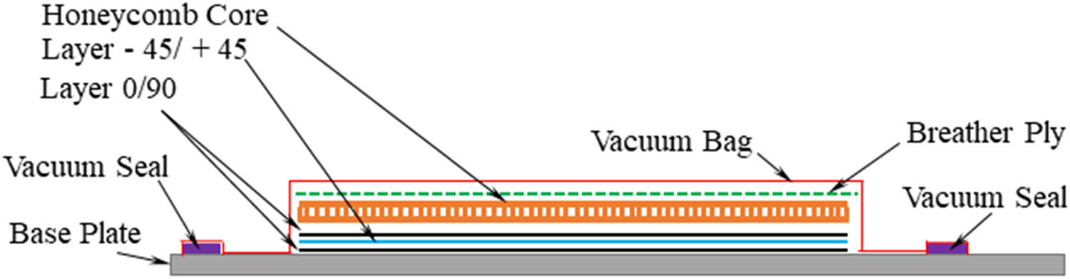
The specimen was prepared throughout the production process using the hand lay-up technique. During the procedure, each ply was handled exclusively by hand and stacked layer by layer to the required thickness. This was accomplished by sequentially stacking layers of 0/90 directional carbon fiber, −45/45 directional carbon fiber, 0/90 directional carbon fiber, and honeycomb core for the first step of the manufacturing. During the interlayer preparation process, the resin and hardener mixture was poured (in a 2:1 solution ratio) and pushed using a roller to ensure the resin was disseminated evenly and equally. The curing process was then performed after all the composite materials had been sequentially placed. Vacuum was used during the curing process to reduce the specimen’s porosity. At room temperature, the curing process was completed in 10 h.
The preparation of the composite layer for the second stage continued after the progress was accomplished in the first stage. All these layers were layered above the honeycomb, with the addition of a carbon layer arrangement in the 0/90 direction, followed by the −45/+45 direction, and finally, the 0/90 direction. Similar to the previous step, this also included the addition of resin and hardener. Additionally, a vacuum operation was carried out once the preparation was completed to lower the porosity of the specimen. Figures 3–7 show the detailed plan of the composite layers. Specifically, Figure 7 shows that there were foam/air bubbles frozen on the right side of the specimen, proving that the vacuum process can lift the air trapped in the resin.
Schematic of the composite layer specimen manufacturing for the first step.

The vacuum operation during the curing process for the first stage.

Schematic of the composite layer specimen manufacturing for the second step.

The vacuum operation during the curing process for the second stage.

Specimen material after the curing process before the cut using a waterjet cutting machine. Foam/air bubbles frozen on the right side of the specimen are seen (red arrow), proving that the vacuum process can lift the air trapped in the resin.
To comply with the American Society for Testing and Materials (ASTM) D7264 test guidelines, the specimen was divided into six parts using a waterjet cutting machine once the curing procedure was completed. This technique cuts the specimens with the least amount of precision feasible while minimizing harm to the specimen. Figure 8 shows the specimen after the waterjet cutting process.

Sandwich structure specimen ready for testing.
3.4 Mechanical testing setup and results
The three-point bending test was carried out using the ASTM D7264 standard test method, which is a test standard for polymer composite matrices. The test procedure requires that the entire length of the specimen is 20% longer than the length of the supporting span. To comply with this standard, the length of the specimen used was 250 mm, with a support span of 200 mm. The tests were carried out using the RTF 2410 test machine made by A&D Japan. This machine had an accuracy of ±0.5% with a sampling rate of 1 ms to improve testing accuracy. Figure 9 shows the laboratory testing setups. A loading speed of 1 mm·min−1 was used during the testing procedure. The specimen immediately ceases loading if it fails or breaks. Table 3 displays the test’s results.

Laboratory testing setup.
Laboratory testing results
| Test no. | Width average | Maximum point load | Maximum facing stress | Breakpoint displacement |
|---|---|---|---|---|
| (mm) | (N) | (MPa) | (mm) | |
| 1 | 25.06 | 200.27 | 251.91 | 6.8 |
| 2 | 25.39 | 215.37 | 270.90 | 7.9 |
| 3 | 25.03 | 171.67 | 215.93 | 6.9 |
| 4 | 25.03 | 178.94 | 225.08 | 6.1 |
| 5 | 25.06 | 193.11 | 242.90 | 6.7 |
| 6 | 24.8 | 176.2 | 221.63 | 6.2 |
| Average | 25.06 | 189.26 | 238.06 | 6.8 |
Based on the testing results in Table 3, the average maximum point load was 189.26 N with a maximum point stress for facing of 238.06 MPa. Then, the average breaking point was obtained at a 6.8 displacement. Stress was obtained using Eq. (5), which is obtained from the ASTM C393 procedure [26].
4 Method and material properties
4.1 Flowchart and research procedures
The methodology in this study began by studying previous studies on a sandwich structure. Then, we proceeded with specimen manufacturing using the vacuum molding method. The next step was mechanical testing, which was carried out to obtain the maximum flexural strength from the sandwich structure through three-point bending. The strength obtained was mainly used to find material properties from the sandwich structure constituents. The method used for material calibration was mix and match. The author made a matrix derived from the material properties of both parts collected from various articles. Then, one by one, it was tried until the maximum flexural strength was found to be similar to the mechanical results. Next, the study continued with parametric studies using material properties that were obtained. Parametric studies included four tests (three-point bending, tensile test, compression test, and torsional test) and two core variations (geometry and material). The study proceeded with mesh convergence studies to determine how the mesh’s effect changes the specimen’s maximum strength. In addition, convergence studies were also conducted to determine the mesh configuration suitable for use in future studies. Figure 10 is the methodological scheme used in this study.

Methodology schematic of the present study.
4.2 Finite element method
FInite element method started with specimen modeling with a size that was obtained, both from the producer datasheet and direct measurement. Figure 11 shows a general-size drawing of the sandwich structure. The core had a 5 mm thickness, a core cell of 6.5 mm long, 5 mm wide, and a wall thickness of 0.11 mm. The facing consisted of three layers of carbon fiber cloth, with each layer having a 0.1 mm thickness. Carbon fiber modeling used composite ply in the lamina feature. The size of the overall specimen length and width will be presented in the testing procedure and boundary conditions because each test has different requirements.

Cell size and sandwich thickness.
This section also discusses mesh configuration, interaction, and material properties. Honeycomb modeling used the Fusion 360 framework while facing modeling used the ABAQUS Framework. A tie constraint was used to model the bonding of the facing and core parts. This constraint connected nodes from honeycomb as slaves and surfaces from facing as masters. The constraint tie was used to ensure the relationship between the facing and core was inseparable so that the strength of the material could be calculated in perfect conditions.
4.2.1 Mesh configuration
Mesh configuration is important because it defines the material behavior. Both core and facing parts used the S4R meshing type. The author used a shell in this study to speed up computation and facilitate the modeling of Hashin damage (HSNCRFT) on the facing, which was a carbon fiber. The facing part of the sandwich had a mesh size of 1 mm, and the core part was 2.25 mm. This difference in size is shown in Figure 12. This mesh configuration was chosen because of fast computing time. Computing time will significantly increase as the meshing becomes smaller. Also, for this size, a small margin of error comparing smaller mesh sizes was achieved. Results from smaller meshing were not significantly different from this meshing configuration.

Mesh difference between facing and core part of sandwich modeling.
4.2.2 Material configuration
4.2.2.1 Nomex honeycomb
Nomex-Aramid honeycomb was used as a core filling because it mainly had a small density, and its honeycomb shape naturally had good strength. Nomex-Aramid had material properties as shown in Table 4 (ρ – density, E – Young’s modulus, ν – Poisson’s ratio, G – shear modulus). The material properties were referred to as local material direction (1 = X, 2 = Y, 3 = Z). These material properties were obtained from the study of Roy et al. [11]. This study investigated the individual strengths of the Nomex-Aramid honeycomb. These material properties had been through benchmarking with three-point bending mechanical testing and achieved good margin results.
Material properties of the Nomex-Aramid honeycomb [11]
| ρ (g·cm−3) | E 1 (MPa) | E 2 (MPa) | E 3 (MPa) | ν1 (−) | ν2 (−) | ν3 (−) | G 1 (MPa) | G 2 (MPa) | G 3 (MPa) |
|---|---|---|---|---|---|---|---|---|---|
| 0.64 | 5,200 | 4,400 | 4,400 | 0.24 | 0.24 | 0.24 | 1,400 | 1,400 | 1,400 |
4.2.2.2 Carbon fiber
Carbon fiber is a material with a high strength-to-weight ratio [27], which indicates carbon fiber has very high strength and is very lightweight. This makes carbon fiber very suitable for use as a facing of sandwich structures. Material properties are needed for parameters in numerical simulation. The Young’s modulus of the carbon fiber was obtained from the carbon fiber datasheet provided by the manufacturer (Torayca, United States). The shear modulus and Poisson’s ratio were obtained from Isbilir and Ghassemieh [28]. These material properties are shown in Table 5 (ρ – density, E – Young’s modulus, ν – Poisson’s ratio, G – shear modulus). The material properties were referred to as local material direction (1 = X, 2 = Y, 3 = Z). The arrangement of material properties has been through benchmarking and has achieved good margin results compared to real three-point bending mechanical testing. As stated before, in real specimens, carbon fiber consists of three plies arranged in (0/90/+45/−45/0/90) configuration for overall good mechanical properties [29].
| ρ (g·cm−3) | E 1 (MPa) | E 2 (MPa) | ν1 (−) | G 12 (MPa) | G 23 (MPa) | G 31 (MPa) |
|---|---|---|---|---|---|---|
| 1.76 | 135,000 | 8,200 | 0.3 | 4,500 | 4,500 | 3,000 |
The Hashin damage criterion was used in this study. The detailed parameters of the Hashin damage criterion used in this study are presented in Table 6 (S t = tensile strength, S c = compressive strength, S s = shear strength, G ft = tensile fracture energy, G fc = compressive fracture energy). These criteria had been through benchmarking and had achieved good margin results compared to real three-point bending mechanical testing.
Hashin criterion and damage evolution parameters [30]
| Parameter | Value |
|---|---|
| S t1 (MPa) | 2,471 |
| S t2 = S t3 (MPa) | 62 |
| S c1 (MPa) | 2,597 |
| S c2 = S c3 (MPa) | 190 |
| S s1 = S s2 = S s3 (MPa) | 81 |
| G ft1 (N·mm−1) | 95 |
| G fc1 (N·mm−1) | 103 |
| G ft2 (N·mm−1) | 0.2 |
| G fc2 (N·mm−1) | 0.2 |
The damage stabilization of 0.001 was adopted in this study, which provided good results and faster numerical simulation. Also, the smaller the damage stabilization number, the time needed for numerical simulation time increased substantially [30].
4.2.2.3 Lamina configuration
Lamina configuration is a setting that defines fiber composite orientation. Carbon fiber composite consists of three plies. The first ply is 0/90, the second ply is 45/−45, and the third ply is 0/90. In ABAQUS framework, modelling all plies as one direction is needed. Therefore, from original three plies, it is needed to break down into six plies. Figure 13 shows the configuration of lamina for carbon fiber composite. The direction for lamina setting was 0/90/45/−45/0/90.

Lamina configuration.
4.2.2.4 Hanshin failure criterion
The Hashin damage criterion is based on the work of Hashin and Rotem [3,31]. Hashin proposed a single equation to predict the damage initiation of the composite. The present work used Hashin damage as one of its parameters and there were four possible failure modes with four corresponding indexes:
where
4.3 Boundary conditions
The boundary conditions of each numerical simulated mechanical test are based on standard procedures used in real-condition mechanical testing. These testing procedures play a vital role in determining the specimen size, which then affects how boundary conditions are created in numerical simulation. In addition, this procedure is also a reference in calculations used in determining the stress of the test specimen. These are expected to increase the accuracy of numerical simulation results. There are four numerical simulated mechanical tests in the present study: three-point bending, tensile test, compression test, and torsional test.
4.3.1 Three-point bending
Three-point bending boundary conditions are made based on ASTM D7264. The schematic of boundary conditions is shown in Figure 14. The load was placed on arrows marked with the letter P, while the support span was placed on P/2. The length of the support span was 200 mm, the overall length of the modeling was 254 mm, and the overall length of the model must be 20% longer than the support span [25]. The details of model dimensions are shown in Figure 15. Based on the test procedure, the boundary conditions of three-point bending simulation were designed and shown in Figure 16.
![Figure 14
Three-point bending testing setup illustration (in mm) [25].](/document/doi/10.1515/rams-2023-0177/asset/graphic/j_rams-2023-0177_fig_014.jpg)
Three-point bending testing setup illustration (in mm) [25].
![Figure 15
Model dimensions for three-point bending numerical simulation (in mm) [26].](/document/doi/10.1515/rams-2023-0177/asset/graphic/j_rams-2023-0177_fig_015.jpg)
Model dimensions for three-point bending numerical simulation (in mm) [26].

Boundary conditions for three-point bending.
Eq. (5) was used to calculate the facing bending stress of the specimen model and was obtained from ASTM C393. This equation was chosen to calculate only the facing bending stress [26]. The overall sandwich stress cannot be calculated because the sandwich structure thickness in the present study was not the same along the length.
where
The pin shown in letter A is a fixed support span that held the model when the bending test was carried out. On point A, an encase setting was applied where U 1 = U 2 = U 3 = UR 1 = UR 2 = UR 3 = 0 to simulate the static pin on the model. Meanwhile, point B was given a displacement control setting in the U 2 direction as long as −15 mm to simulate the bending loading on the model. For the interaction between the jig and the specimen, interaction properties were used with a friction coefficient of 0.2.
4.3.2 Tensile test
Boundary conditions for tensile testing were made in accordance with the ASTM D3039 procedure. The specimen size, clamp size, and testing setup were obtained from this procedure. The overall model length is 254 mm, and the clamp length is 50 mm [34]. The designed boundary conditions for the tensile simulation is presented in Figure 17. Meanwhile, the stress calculation (Eq. (6)) was used only to calculate the facing stress of the sandwich structure, as mentioned previously. Eq. (6) was used to calculate the stress load on the facing part of the sandwich structure. This equation was obtained from ASTM C 364 and deemed suitable for sandwich structure application.
where
Load modeling is detailed in Figure 17. Clamp modeling used the coupling feature on carbon fiber facing. Letter A, shown in Figure 17, was given displacement control with U 2 as long as 10 mm to simulate tensile loading on the model, and Letter B was given boundary with U 1 = U 2 = U 3 = UR 1 = UR 2 = UR 3 = 0 to simulate the static clamp on the model. F is the direction of the loading.

Boundary conditions for the tensile test.
4.3.3 Compression test
Boundary conditions for compression testing were made in accordance with ASTM D6041 [35]. The compression test aims to test the overall edgewise strength of the sandwich material under compression loading. The detailed boundary condition setup is shown in Figure 18. The overall model length was 155 mm and was clamped on both sides, where F is the loading direction. The detailed model dimensions are shown in Figure 19. The dimensions of the sandwich material modeling were 155 mm long, 25 mm wide, and 5.6 mm thick. As stated before, the procedure from real mechanical testing was used to mimic real testing scenarios to increase numerical simulation accuracy.

Boundary conditions for the compression test.
![Figure 19
Model dimensions (in mm) for the compression test [35].](/document/doi/10.1515/rams-2023-0177/asset/graphic/j_rams-2023-0177_fig_019.jpg)
Model dimensions (in mm) for the compression test [35].
The detailed boundary conditions for the compression test are shown in Figure 19. The clamp was modeled with coupling features on carbon fiber facing 65 mm from each end of the model. Point A was given displacement control as long as −10 mm in the U 2 direction to simulate compression loading on the model. Point B was given a boundary setting with U 1 = U 2 = U 3 = UR 1 = UR 2 = UR 3 = 0 to simulate the static clamp on the model. F is the loading direction.
4.3.4 Torsional test
Torsional test boundary conditions are made in accordance with the study of Li et al. [14]. In this study, mechanical testing and numerical simulation were carried out. The dimensions of the model were 270 mm long, 70 mm wide, and 5.6 mm thick (Figure 20). Clamp modeling used coupling features that took place on the carbon fiber facing 20 mm from each end of the model. Point A in Figure 21 was given a displacement control in the UR 2 direction as large as 4 rad, which was to simulate torque loading on the model. Point B was given a boundary setting (U 1 = U 2 = U 3 = UR 1 = UR 2 = UR 3=0) to simulate the static clamp that held the specimen.
![Figure 20
Specimen dimensions for torsional testing (in mm) [14].](/document/doi/10.1515/rams-2023-0177/asset/graphic/j_rams-2023-0177_fig_020.jpg)
Specimen dimensions for torsional testing (in mm) [14].

Boundary conditions for torsional testing.
5 Results and discussion
After finding the procedure and setting up boundary conditions, we will discuss the results of the numerical simulation. This section will present stress vs strain specimen data in the three-point bending experiment, tensile test, compression, and torsional testing. Then, it will also be accompanied by a mesh convergence study graph to determine the effect of mesh on the results of numerical simulation. Core variations study will also be discussed in this section. There are two studies of variation (geometric and material properties). Visual results of numerical simulation are also presented in this section.
5.1 Three-point bending
Three-point bending was done to estimate the flexural strength and fracture characteristics from flexural loading. Numerical simulation shows that failure in sandwich construction began from the skin that had direct contact with the indenter (upper skin). The core and lower skin remained intact when the whole model reached its maximum strength.
Generally, when a model is given a bending load, the failure starts from the lower part of the model (lower skin). However, in the case of carbon fiber Nomex-Aramid honeycomb sandwich construction, the damage that occurred during the bending load started from the upper skin (Figure 22). This phenomenon was due to the huge difference in the strength and density between the skin and core. Because of this difference, the loading from the indenter cannot be distributed throughout the model, and the stresses will accumulate on the upper skin, thus failing in the first place. After the upper skin fails, the core will bear the load and experience damage, and at a certain point, after the load has accumulated, the lower skin will eventually fail.

Simulation results of the three-point bending.
Figure 23 shows the numerical simulation results and detailed Hashin damage criterion contour. It can be seen that the specimen had several strength peaks. This phenomenon occurred because the failure of the composite ply did not occur at the same time, but its failure occurred separately in accordance with the load in every ply. When displacement reached 6.3 mm (Figure 23, point A), the global loading occurred where the whole model bore the load. The composite structure has shown the germ of failure at this period, although the total breakdown was not imminent. This instance can be seen in Figure 22: 0° ply with

Hashin damage criterion and damage evolution of the specimen in three-point bending’s numerical simulation.
The stress shown in Figure 23 is the stress that occurs on the facing part of the sandwich structure (facing stress). The facing stress was used to represent the whole model strength and calculated using Eq. (5). Facing stress was directly affected by the failure both on the core and facing (Hashin damage). Figure 24 shows the correlation between the facing stress and Hashin damage criterion. In the case of bending loading, the Hashin criterion had a direct correlation with facing stress. Proven failure on facing (fiber compression and matrix compression failure) had caused the model to fail, which was marked by steep decreases in facing stress. Figure 24 shows the effect of facing failure on the overall sandwich strength under loading bending.

Correlation between Hashin damage and model facing stresses under bending loading (A: facing failure, and B: core crushing under bending loading).
Mesh convergence studies showed a relationship between the number of elements and the maximum point load of the specimen. A mesh convergence study was carried out by changing the mesh sizing on the facing part (carbon fiber) of the specimen. The results showed an exponential graph. A drastic decrease occurred in the range of 680 (mesh size, 3 mm) to 2,873 elements (mesh size, 1.5 mm). After increasing the number of elements to 6,350 (mesh size, 1 mm) onward, the chart began to show a downward trend. From Figure 25, it can be concluded that the mesh convergence of three-point bending occurred on a 1 mm mesh with a number of elements of 6,350 elements and had a maximum point load of 205 N.

Mesh convergence of the three-point bending’s numerical simulation result.
5.2 Tensile loading
Tensile test numerical simulation was done to estimate the sandwich structure's tensile strength and also to study the sandwich structure behavior under tensile loading. Under tensile loading, facing (carbon fiber composite) will be experiencing a total failure. When this occurs, all of the tensile force will be borne by the sandwich structure core (Nomex-Aramid). Numerical simulation results from the sandwich structure carbon fiber Nomex-Aramid honeycomb under tensile load are shown in Figure 26 (

Hashin damage criterion and damage evolution of the specimen in the tensile test’s simulation.
The stress shown in Figure 26 is the stress that occurs on the facing part of the sandwich structure (facing stress). The facing stress was used to represent the whole model strength and calculated using Eq. (6). Facing stresses were directly affected by failure both on the core and facing (Hashin damage criterion). Figure 27 shows the correlation between the facing stress and Hashin damage criterion. In the case of tensile loading, the Hashin criterion had a direct correlation with facing stress. There were two face sheet failures that met its criterion: the matrix failure under tensile loading and fiber breakage under tensile loading. Matrix failure did not affect the overall strength of the sandwich structure, but fiber failure did. The failure on facing (fiber tensile and matrix tensile failure) had caused the model to fail, which was marked by steep decreases in the facing stress.

Correlation between the Hashin damage and model facing stresses under tensile loading (A: matrix failure under tensile loading, B: fiber breakage under tensile loading, and c: core bears all tensile loading).
The matrix on the composite is the substance that bonds the fiber together as a filler between those fibers. Thus, under certain loading, those matrixes always fail first. After the failure of the matrix, fibers will endure the loading until its break. Therefore, the matrix failed first before the fiber did. Figure 27 shows the effect of facing failure on the overall sandwich strength under loading bending.
The mesh convergence study was conducted on the tensile test by changing the mesh size of the facing part in specimen modeling. The results of the mesh convergence study are shown in Figure 28. The tensile tests mesh convergence occurred in exponential graphs where the maximum stress on the number of elements 824 (mesh size 4 mm) to 3,450 (mesh size 1 mm) still increased significantly. Then, the chart began to show a constant trend on the number of elements 4,554 (mesh size 0.75) onward. It can be concluded that in the tensile test, the numerical simulation mesh convergence occurred on the mesh size of 0.75 with 4,554 elements. The maximum point load occurred when the mesh convergence was 14,450 N.

Mesh convergence study of the tensile test’s simulation.
5.3 Compression loading
A compression test was performed to estimate the maximum compression strength of the sandwich structure. In addition, the characteristics of the sandwich against compressive load can also be known. The results of the stress vs displacement graph and damage evolution for facing and core parts are shown in Figure 29. It was known from compression numerical simulation results that the maximum compressive strength of the model was 266 MPa, which occurred at 0.125 mm displacement. At this point (Figure 29, point A), failure at the core occurred, causing the model to buckle. At this point, there was no sign of Hashin damage initiation meeting its criterion. Model failure had occurred sideways because there was a limitation from the carbon fiber facing to move in the longitudinal direction. This limitation was due to the difference in mechanical properties between the carbon fiber facing and Nomex-Aramid core (carbon fiber is way stiffer than Nomex-Aramid). Therefore, in order to receive compressive load, the model started to buckle in the lateral direction (sideways). This movement was more obvious in the displacement range of 0.6–2.85 mm (Figure 29, points B and C).

Results of the compression test’s simulation.
The Hashin damage criterion under a compression load is shown in Figure 30 (

Hashin damage contour under compression.
The stress shown in Figure 29 was the stress that occurred on the facing part of the sandwich structure (facing stress). The facing stress was used to represent the whole model strength and calculated using Eq. (6). Facing stress was directly affected by failure both on the core and facing (Hashin damage criterion). Figure 31 shows the correlation between the facing stress and Hashin damage criterion. In the case of compression loading, the Hashin criterion did not correlate with the failure of the model. The failure of the model was due to core buckling. This buckling is clearly shown in Figure 32 (compression). Because of this buckling, the local stress arose and caused facing to bear excessive loading on those buckling epicenters, thus failing. Facing failure still affected the overall strength of the model. As shown in Figure 31 (point B), the failure on facing with matrix under tensile loading type caused a drop in facing stress. Figure 31 shows the effect of the core and facing failure on the overall sandwich strength under compressive loading.

Correlation between the Hashin damage and model facing stresses under tensile loading (A: core buckling had occurred, and B: MTCRT affecting drop on facing stress).

The deployed model is under compressive loading.
The mesh convergence on compression test modeling was done by changing the mesh size on the facing part (carbon fiber lamina) of the sandwich structure. The meshing size in the study was 5–0.25 mm. The Y-axis contains the maximum load (N). The results of the convergence study (Figure 33) showed a drastic reduction in the maximum compression load in the number of mesh elements from 507 (mesh size 2 mm) to 2,640 (mesh size, 0.625 mm). The chart shows a constant trend in the number of elements from 3,800 (mesh size, 0.5 mm) onward. From this finding, it can be concluded that the mesh convergence for compression numerical simulation occurred for a mesh size of 0.5 mm with 3,998 elements. The maximum compression load was observed when mesh convergence was 2623.97 N.

Mesh convergence study of the compression test’s simulation.
5.4 Torsional loading
Torsional tests were performed to estimate the maximum twisting strength of the sandwich structure. The characteristics of the sandwich structure, when subjected to twisting loads, can also be found through this experiment. The torsional numerical simulation results showed that the model could withstand torsional load as large as 88.9 N m at 1.34 rad, which indicates that the sandwich material had good torsional properties. In torsional loading, the model experienced two phases: the global load and the local load. In the global load phase, the facing part of the sandwich is still intact. This facing part distributed load on the entire model (Figure 34, points A and B). After the model reached the maximum strength (circa 1.34 rad), failure on the carbon fiber facing occurs (Figure 34, point C). This occurrence was observed with a steep decrease in the torsional strength. This strength decreased due to facing failure after the facing could no longer distribute the load on the entire model when the local load had arisen. This local load destroyed the core part because of its centralized (localized) force (Figure 34).

Results of the torsional test’s simulation.
Hashin damage failure in the carbon fiber composite under a torsional load is shown in Figure 35 (Hashin damage failure at the end of numerical simulation). Basically, composite failure occurred in all plies of the composite, but the location and type of failure were different. In one ply, two types of failure can occur that are different in places. In general, failure in a composite occurred in the middle section because of excessive compressive load (Figure 30,

Hashin failure criterion of the carbon fiber composite under torsional loading.
The stress shown in Figure 36 shows that the torque occurred on the whole model of the sandwich structure. The torque was used to represent the whole model strength extracted directly from the simulation. The torque was directly affected by failure both on the core and facing (Hashin damage criterion). Figure 36 shows the correlation between the torque and Hashin damage criterion. In the case of torsional loading, the Hashin criterion did not correlate with the failure of the model. The failure on facing came first before the model did. The failure of the model was mainly because the core was crushed by two face sheets under a torsional load. Figure 36 shows the effect of core and facing failure on the overall sandwich strength under torsional loading.

Correlation between Hashin damage and the facing stress under tensile loading (A: facing failure).
Mesh convergence on torsional numerical simulation was done by changing the mesh size on the facing part of the sandwich structure (carbon fiber), and the core part remained constant (2.25 mm in size). The variant of mesh sizing ranged from 6 to 0.5 mm. The y-axis of mesh convergence used the reaction moment at a 0.004 increment time. This method was used because reaching the failing point for all of the numerical simulations could take days for just one numerical simulation. This method was deemed accurate because the difference in strength at the failing point can be seen even on the first increment. The results of the convergence study (Figure 37) showed a drastic reduction in the torsional load in the number of mesh elements from 552 (mesh size, 6 mm) to 4,725 (mesh size, 2 mm). The chart shows a constant trend in the number of elements from 18,900 (mesh size, 1.0 mm) onward. From this finding, it can be concluded that mesh convergence for torsional numerical simulation occurred at a mesh size of 1.0 mm with 18,900 elements. The number of elements for the torsional load at 0.004 rad was 127.71.

Mesh convergence study of the torsional test’s simulation.
5.5 Geometrical change study
The study was conducted by changing the geometrical shape of the sandwich core into an octagonal, which was previously a hexagonal honeycomb. Two numerical simulations were carried out to study the differences between the two, namely the flexural strength from three-point bending. The mesh configuration (1 mm facing and 2.25 mm core) and material properties had the same configuration between the geometries. This study was conducted to underline the geometric effect on the overall strength of the sandwich material. The difference in the material core is shown in Figure 38.

The size difference for core shapes.
A three-point bending comparison was carried out to determine the effect of differences in the core geometry on the flexural strength of the sandwich material as a whole. Figure 39 compares the results of three-point bending tests from both geometries. The octagonal specimen had a higher maximum flexural strength (349 MPa) when compared to the hexagonal variant (254 MPa). This phenomenon was caused by the difference in the core cell size in octagonal and hexagonal variants. This difference increased the strength of the facing and could minimize the local stress that occurred in the sandwich structure. With minimal local stress, the fundamental weakness of the heterogeneous materials can be overcome by decreasing the core cell size of the sandwich core. This phenomenon was caused by the difference in the size of the core cell. The core with an octagonal shape had a smaller cell size compared with that with a hexagonal shape. Thus, the octagonal shape had a larger area for transferring the load from the upper skin to lower skin. This difference can be clearly seen in Table 7.

Comparison between the hexagonal and octagonal cores in the three-point bending test’s simulation.
Comparison between the area and facing stress between two core geometries
| Core shape | Area (mm2) | Facing stress (MPa) |
|---|---|---|
| Hexagonal | 254.957 | 258.052 |
| Octagonal | 348.139 | 346.784 |
5.6 Material variation study
Material variation studies were conducted to determine the effect of material changes on the strength of the sandwich structure. In this study, conducted by changing the material properties of the core sandwich, three variants were compared, namely Nomex-Aramid, which was the main material, aluminum, and stainless steel. The mesh size was the same in each material, namely 1 mm for the facing size and 2.25 mm for the core size. This was done to emphasize experiments on the effect of the core material on the overall strength of the sandwich structure. Three-point bending was used to test the differences between the three materials. The test results (Figure 40) found that the sandwich structure with a stainless steel core had the largest ultimate facing flexural stress of 411.4 MPa, followed by aluminum with a strength of 321.2 MPa, and finally, Nomex-Aramid with a strength of 258 MPa.

Comparison of the numerical results: material changes in the three-point bending test.
The replacement of the core material significantly impacted changes in the facing flexural stress of the sandwich structure. This is evidenced in Figure 40. The higher the strength of the core, the higher the strength of the facing flexural strength, which also improved the overall strength of the sandwich structure. The order of stiffness of the material was Nomex-Aramid (the weakest), aluminum, and stainless steel (the strongest). The test results were also similar for stiffness order. The Young’s modulus of the core sandwich also affected the stiffness of the overall sandwich structure. The stiffer the core, the stiffer the sandwich structure. The three materials had a similar graphic shape with one main peak and several follow-up peaks, which is the nature of the sandwich structure. The assessment and characterization introduced in this work can be recommended to be used for other composite materials, for example, bio-material-based composites from sea sand [36,37], Cantala [38,39], Salacca Zalacca [40,41], egg shells [42,43,44], and hybrid and core materials [45,46,47].
6 Conclusions
Various numerical simulations were conducted on the sandwich structures, starting from three-point bending benchmarking and conducting tensile, compression, and torsional tests. The experiment was then continued by comparing the geometry and material properties of the sandwich core to determine the effect on the sandwich structure as a whole. The following conclusions are drawn:
The heterogeneous sandwich structure has a big drawback. After facing failure occurs, the local stress arises, which can cause the failure of the whole sandwich structure. This occurs in all forms of loadings. Therefore, the right material composition is needed to avoid this.
The sandwich structure is a resilient structure, which is proved by the fact that the model does not experience a complete failure when facing (carbon fiber) part fails. This is due to the sandwich structure being made up of two materials that bond together and possess two material properties that fulfill each other's weaknesses.
The sandwich structure model under a three-point bending load yielded a strength of 254 MPa at a displacement of 7.5 mm under a tensile load of 970 MPa at a displacement of 2.9 mm under a compressive load of 266 MPa at a displacement of 0.125 mm and under a torsional load of 88.9 Nm at 1.25 rad.
In three-point bending, the dominant damage on the composite was fiber buckling under compressive loading and matrix crushing that occurred in fiber directions of 0° and 45°.
In the tensile numerical simulation, the dominant damage on the composite was fiber breakage under a tensile loading that occurred in fiber directions of 0° and −45° and matrix cracking under a tensile loading that occurred in fiber directions of 90° and 45°.
In compression numerical simulation, all of the Hashin damage criteria occurred in the compression model but on different plies. The 0° ply experienced fiber breakage under a tensile loading and fiber buckling under a compressive loading. The 90° ply experienced matrix crushing under a compressive load and matrix cracking under a tensile load.
In the torsional numerical simulation, the dominant damage that occurred was matrix cracking under a tensile load and matrix crushing under a compressive load on all plies.
Substituting geometry for the flexural strength had a significant effect. The tighter the sandwich core cell, the greater the flexural strength of the sandwich structure. This was due to minimized local failure of the sandwich material.
Replacement of the material properties of the sandwich structure affected the maximum strength of the sandwich structure. The higher the core material strength, the higher the maximum strength of the sandwich material.
Based on the present studies, the characteristics of sandwich materials in the form of the test specimen in numerical simulation are obtained. This, of course, will only give an idea of the characteristics of the sandwich material in general. In future studies, it can be explored how sandwich structures work in their real form, as it is known that composite materials have different behaviors in the form of finished objects/parts. This certainly needs special attention from material engineers when using sandwich structures in the design.
Acknowledgments
This work is successfully completed by collaboration of Department of Mechanical Engineering, Universitas Sebelas Maret (UNS) and National Research and Innovation Agency (BRIN). Supports from Laboratory of Design and Computational Mechanics and Laboratory of Material, Faculty of Engineering – Faculty of Engineering, UNS are highly appreciated by the authors.
-
Funding information: The authors state no funding involved.
-
Author contributions: All authors have accepted responsibility for the entire content of this manuscript and approved its submission.
-
Conflict of interest: The authors state no conflict of interest.
-
Data availability statement: All data generated or analyzed during this study are included in this published article [and its supplementary information files].
References
[1] Jayaram, R. S., V. A. Nagarajan, and K. P. V. Kumar. Mechanical performance of polyester pin-reinforced foam filled honeycomb sandwich panels. Science and Engineering of Composite Materials, Vol. 25, No. 4, 2018, pp. 797–805.Search in Google Scholar
[2] Mahmoud, E. R. I., A. M. Shaharoun, A. Aljabri, H. Almohamadi, and M. Farhan. Prospects and State of the Glass Industry in Saudi Arabia and a preliminary assessment of the quality of Glass and Glass-Ceramics Fabrication. Mekanika: Majalah Ilmiah Mekanika, Vol. 21, No. 2, 2022, pp. 85–94.10.20961/mekanika.v21i2.64294Search in Google Scholar
[3] Hashin, Z. Analysis of composite materials-A survey. Journal of Applied Mechanics, Vol. 50, No. 3, 1983, pp. 481–505.10.1115/1.3167081Search in Google Scholar
[4] Adhana, I., D. F. Smaradhana, D. Ariawan, W. W. Raharjo, and B. Yusuf. Effect of screw rotation speed on mechanical properties and morphology of Abs/Mcc composites. Mekanika: Majalah Ilmiah Mekanika, Vol. 22, No. 1, 2023, pp. 23–29.10.20961/mekanika.v22i1.70884Search in Google Scholar
[5] Ramadhan, M. R. B., M. S. Salim, E. Fanani, D. Ariawan, and E. Surojo. Effect of alkaline treatment and fumigation (Fumigation) on the mechanical properties of fiber unsaturated polyester-cantula composite with compression molding method. Mekanika: Majalah Ilmiah Mekanika, Vol. 21, No. 2, 2022, pp. 40–47.10.20961/mekanika.v21i2.51493Search in Google Scholar
[6] Castanie, B., C. Bouvet, and M. Ginot. Review of composite sandwich structure in aeronautic applications. Composites Part C: Open Access, Vol. 1, 2020, id. 100004.10.1016/j.jcomc.2020.100004Search in Google Scholar
[7] Li, H., S. Tu, Y. Liu, X. Lu, and X. Zhu. Mechanical properties of L-joint with composite sandwich structure. Composite Structures, Vol. 217, 2019, pp. 165–174.10.1016/j.compstruct.2019.03.011Search in Google Scholar
[8] Wada, A., T. Kawasaki, Y. Minoda, A. Kataoka, S. Tashiro, and H. Fukuda. A method to measure shearing modulus of the foamed core for sandwich plates. Composite Structures, Vol. 60, No. 4, 2014, pp. 385–390.10.1016/S0263-8223(03)00041-2Search in Google Scholar
[9] Neveu, F., B. Castanié, and P. Olivier. The GAP methodology: A new way to design composite structures. Material Design, Vol. 172, 2019, id. 107755.10.1016/j.matdes.2019.107755Search in Google Scholar
[10] Rayjade, G. R. and G. V. R. S. Rao. Study of composite sandwich structure and bending characteristics–A review. International Journal of Current Engineering and Technology, Vol. 5, No. 2, 2015, pp. 797–802.Search in Google Scholar
[11] Roy, R., S. J. Park, J. H. Kweon, and J. H. Choi. Characterization of Nomex honeycomb core constituent material mechanical properties. Composite Structures, Vol. 117, No. 1, 2014, pp. 255–266.10.1016/j.compstruct.2014.06.033Search in Google Scholar
[12] Xie, S., H. Wang, C. Yang, H. Zhou, and Z. Feng. Mechanical properties of combined structures of stacked multilayer Nomex® honeycombs. Thin-Walled Structures, Vol. 151, 2020, id. 106729.10.1016/j.tws.2020.106729Search in Google Scholar
[13] Soutis, C. Fibre reinforced composites in aircraft construction. Progress in Aerospace Sciences, Vol. 41, No. 2, 2005, pp. 143–151.10.1016/j.paerosci.2005.02.004Search in Google Scholar
[14] Li, M., L. Wu, L. Ma, J. Xiong, and Z. Guan. Torsion of carbon fiber composite pyramidal core sandwich plates. Composite Structures, Vol. 93, No. 9, 2011, pp. 2358–2367.10.1016/j.compstruct.2011.03.024Search in Google Scholar
[15] Seemann, R. and D. Krause. Numerical modelling of Nomex honeycomb sandwich cores at meso-scale level. Composite Structures, Vol. 159, 2017, pp. 702–718.10.1016/j.compstruct.2016.09.071Search in Google Scholar
[16] Jayaram, R. S., V. A. Nagarajan, and K. P. V. Kumar. Mechanical performance of polyester pin-reinforced foam filled honeycomb sandwich panels. Science and Engineering of Composite Materials, Vol. 25, No. 4, 2018, pp. 797–805.10.1515/secm-2017-0039Search in Google Scholar
[17] Safarabadi, M., M. Haghighi-Yazdi, M. A. Sorkhi, and A. Yousefi. Experimental and numerical study of buckling behavior of foam-filled honeycomb core sandwich panels considering viscoelastic effects. Journal of Sandwich Structures and Materials, Vol. 23, No. 8, 2021, pp. 3985–4015.10.1177/1099636220975168Search in Google Scholar
[18] Farrokhabadi, A., S. A. Taghizadeh, H. Madadi, H. Norouzi, and A. Ataei. Experimental and numerical analysis of novel multilayer sandwich panels under three point bending load. Composite Structures, Vol. 250, 2020, id. 112631.10.1016/j.compstruct.2020.112631Search in Google Scholar
[19] Othman, A. R. and D. C. Barton. Failure initiation and propagation characteristics of honeycomb sandwich composites. Composite Structures, Vol. 85, No. 2, 2008, pp. 126–138.10.1016/j.compstruct.2007.10.034Search in Google Scholar
[20] Feng, Y., H. Qiu, Y. Gao, H. Zheng, and J. Tan. Creative design for sandwich structures: A review. International Journal of Advanced Robotic Systems, Vol. 17, No. 3, 2020, pp. 1–24.10.1177/1729881420921327Search in Google Scholar
[21] Anandan, S., G. Dhaliwal, S. Ganguly, and K. Chandrashekhara. Investigation of sandwich composite failure under three-point bending: Simulation and experimental validation. Journal of Sandwich Structures and Materials, Vol. 22, No. 6, 2020, pp. 1838–1858.10.1177/1099636218791162Search in Google Scholar
[22] Harizi, W., J. Anjoul, V. A. Acosta Santamaría, Z. Aboura, and V. Briand. Mechanical behavior of carbon-reinforced thermoplastic sandwich composites with several core types during three-point bending tests. Composite Structures, Vol. 262, 2021, id. 113590.10.1016/j.compstruct.2021.113590Search in Google Scholar
[23] Torayca, ‘T300 Data Sheet’, No. CFA-001, pp. 6–7, 2002, [Online]. Available: www.toraycfa.com/pdfs/T300DataSheet.pdf.Search in Google Scholar
[24] Toray, ‘Nomex Honeycomb’, Toray Advanced Composites, 44, 0, pp. 1–2, 2020, [Online]. Available: https://www.toraytac.com/media/5527e573-2e72-4aa4-bda7-5a49a20fef06/guunTA/TAC/Documents/Data_sheets/Adhesives_and_Core/Honeycomb_core/Nomex-Honeycomb-Core-Aerospace-Grade_PDS.pdf.Search in Google Scholar
[25] ASTM and ASTM D7264/D7264M-07. ‘Standard Test Method for Flexural Properties of Polymer Matrix Composite Materials’, Pennsylvania, United States, 2007.Search in Google Scholar
[26] ASTM and ASTM C393-00. ‘Standard Test Method for Flexural Properties of Sandwich Constructions’, Pennsylvania, United States, 2000.Search in Google Scholar
[27] Sharma, M., S. Gao, E. Mäder, H. Sharma, L. Y. Wei, and J. Bijwe. Carbon fiber surfaces and composite interphases. Composites Science and Technology, Vol. 102, 2014, pp. 35–50.10.1016/j.compscitech.2014.07.005Search in Google Scholar
[28] Isbilir, O. and E. Ghassemieh. Finite element analysis of drilling of carbon fibre reinforced composites. Applied Composite Materials, Vol. 19, No. 3–4, 2012, pp. 637–656.10.1007/s10443-011-9224-9Search in Google Scholar
[29] Rahmani, H., S. H. M. Najafi, S. Saffarzadeh-Matin, and A. Ashori. Mechanical properties of carbon fiber/epoxy composites: Effects of number of plies, fiber contents, and angle-ply Layers. Polymer Engineering and Science, Vol. 54, No. 11, 2014, pp. 2676–2682.10.1002/pen.23820Search in Google Scholar
[30] Duarte, A. P. C., A. Díaz Sáez, and N. Silvestre. Comparative study between XFEM and Hashin damage criterion applied to failure of composites. Thin-Walled Structures, Vol. 115, 2017, pp. 277–288.10.1016/j.tws.2017.02.020Search in Google Scholar
[31] Hashin, Z. Failure Criterion for Unidirectional Fiber Composites. Journal of Applied Mechanics, Vol. 7, No. 4, 1980, pp. 448–464.Search in Google Scholar
[32] Barbero, E. J., F. A. Cosso, R. Roman, and T. L. Weadon. Determination of material parameters for Abaqus progressive damage analysis of E-glass epoxy laminates. Composites Part B: Engineering, Vol. 46, 2013, pp. 211–220.10.1016/j.compositesb.2012.09.069Search in Google Scholar
[33] Simulia. ABAQUS standard, User’s manual. Simulia, Rhode Island, United States, 2000.Search in Google Scholar
[34] ASTM. ASTM D3039/3039M-00: Standard Test Method for Tensile Properties of Polymer Matrix Composite Materials. Pennsylvania, United States, 2000.Search in Google Scholar
[35] ASTM. ASTM D3410/D3410M-03: Standard Test Method for Compressive Properties of Polymer Matrix Composite Materials with Unsupported Gage Section by Shear Loading. Pennsylvania, United States, 2003.Search in Google Scholar
[36] Akbar, H. I., E. Surojo, D. Ariawan, A. R. Prabowo, and F. Imanullah. Fabrication of AA6061-sea sand composite and analysis of its properties. Heliyon, Vol. 7, No. 8, 2021, id. e07770.10.1016/j.heliyon.2021.e07770Search in Google Scholar PubMed PubMed Central
[37] Wang, S., C. Lin, S. Li, M. Chen, and Y. Lu. Effect of CNFs on the mechanical properties and microstructure of early strength seawater sea-sand engineered cementitious composites. Construction and Building Materials, Vol. 307, 2021, id. 124961.10.1016/j.conbuildmat.2021.124961Search in Google Scholar
[38] Sakuri, S., E. Surojo, D. Ariawan, and A. R. Prabowo. Experimental investigation on mechanical characteristics of composite reinforced cantala fiber (CF) subjected to microcrystalline cellulose and fumigation treatments. Composites Communications, Vol. 21, 2020, id. 100419.10.1016/j.coco.2020.100419Search in Google Scholar
[39] Sakuri, S., E. Surojo, D. Ariawan, and A. R. Prabowo. Investigation of Agave cantala-based composite fibers as prosthetic socket materials accounting for a variety of alkali and microcrystalline cellulose treatments. Theoretical and Applied Mechanics Letters, Vol. 10, No. 6, 2020, pp. 405–411.10.1016/j.taml.2020.01.052Search in Google Scholar
[40] Ariawan, D., T. S. Ricai, E. Surojo, S. Hidayatulloh, H. I. Akbar, and A. R. Prabowo. Effect of alkali treatment of Salacca Zalacca fiber (SZF) on mechanical properties of HDPE composite reinforced with SZF. Alexandria Engineering Journal, Vol. 59, No. 5, 2020, pp. 3981–3989.10.1016/j.aej.2020.07.005Search in Google Scholar
[41] Ariawan, D., E. Surojo, J. Triyono, I. F. Purbayanto, A. F. Pamungkas, and A. R. Prabowo. Micromechanical analysis on tensile properties prediction of discontinuous randomized zalacca fibre/high-density polyethylene composites under critical fibre length. Theoretical and Applied Mechanics Letters, Vol. 10, No. 1, 2020, pp. 57–65.10.1016/j.taml.2020.01.009Search in Google Scholar
[42] Rani, G. E., R. Murugeswari, S. Vairamuthu, N. Rajii, F. Mohammad, S. Siengchin, et al. An automated software development for analysis of the morphological-tensile property relationship in egg shell bio-based particulate composites using machine learning algorithms. Composites Part C: Open Access, Vol. 10, 2023, id. 100343.10.1016/j.jcomc.2022.100343Search in Google Scholar
[43] Sunardi, S., D. Ariawan, E. Surojo, A. R. Prabowo, H. I. Akbar, B. Cao, et al. Assessment of eggshell-based material as a green-composite filler: Project milestones and future potential as an engineering material. Journal of the Mechanical Behavior of Materials, Vol. 32, No. 1, 2023, id. 20220269.10.1515/jmbm-2022-0269Search in Google Scholar
[44] Sunardi, S., D. Ariawan, E. Surojo, A. R. Prabowo, H. I. Akbar, A. Sudrajad, et al. Optimization of eggshell particles to produce eco-friendly green fillers with bamboo reinforcement in organic friction materials. Reviews on Advanced Materials Science, Vol. 62, No. 1, 2023, id. 20230111.10.1515/rams-2023-0111Search in Google Scholar
[45] Fanani, E. W. A., E. Surojo, A. R. Prabowo, and H. I. Akbar. Recent progress in hybrid aluminum composite: Manufacturing and application. Metals, Vol. 11, No. 12, 2023, id. 1919.10.3390/met11121919Search in Google Scholar
[46] Tuswan, T., E. N. Sari, A. Ismail, and A. R. Prabowo. Experimental evaluation on palm oil and sesame oil-based resin properties as core sandwich material for lightweight ship structure. International Journal of Engineering, Vol. 35, No. 9, 2022, pp. 1690–1698.10.5829/IJE.2022.35.09C.03Search in Google Scholar
[47] Fanani, E. W. A., E. Surojo, A. R. Prabowo, D. Ariawan, and H. I. Akbar. Recent development in aluminum matrix composite forging: Effect on the mechanical and physical properties. Procedia Structural Integrity, Vol. 33, 2021, pp. 3–10.10.1016/j.prostr.2021.10.002Search in Google Scholar
© 2024 the author(s), published by De Gruyter
This work is licensed under the Creative Commons Attribution 4.0 International License.
Articles in the same Issue
- Review Articles
- Effect of superplasticizer in geopolymer and alkali-activated cement mortar/concrete: A review
- Experimenting the influence of corncob ash on the mechanical strength of slag-based geopolymer concrete
- Powder metallurgy processing of high entropy alloys: Bibliometric analysis and systematic review
- Exploring the potential of agricultural waste as an additive in ultra-high-performance concrete for sustainable construction: A comprehensive review
- A review on partial substitution of nanosilica in concrete
- Foam concrete for lightweight construction applications: A comprehensive review of the research development and material characteristics
- Modification of PEEK for implants: Strategies to improve mechanical, antibacterial, and osteogenic properties
- Interfacing the IoT in composite manufacturing: An overview
- Advances in processing and ablation properties of carbon fiber reinforced ultra-high temperature ceramic composites
- Advancing auxetic materials: Emerging development and innovative applications
- Revolutionizing energy harvesting: A comprehensive review of thermoelectric devices
- Exploring polyetheretherketone in dental implants and abutments: A focus on biomechanics and finite element methods
- Smart technologies and textiles and their potential use and application in the care and support of elderly individuals: A systematic review
- Reinforcement mechanisms and current research status of silicon carbide whisker-reinforced composites: A comprehensive review
- Innovative eco-friendly bio-composites: A comprehensive review of the fabrication, characterization, and applications
- Review on geopolymer concrete incorporating Alccofine-1203
- Advancements in surface treatments for aluminum alloys in sports equipment
- Ionic liquid-modified carbon-based fillers and their polymer composites – A Raman spectroscopy analysis
- Emerging boron nitride nanosheets: A review on synthesis, corrosion resistance coatings, and their impacts on the environment and health
- Mechanism, models, and influence of heterogeneous factors of the microarc oxidation process: A comprehensive review
- Synthesizing sustainable construction paradigms: A comprehensive review and bibliometric analysis of granite waste powder utilization and moisture correction in concrete
- 10.1515/rams-2025-0086
- Research Articles
- Coverage and reliability improvement of copper metallization layer in through hole at BGA area during load board manufacture
- Study on dynamic response of cushion layer-reinforced concrete slab under rockfall impact based on smoothed particle hydrodynamics and finite-element method coupling
- Study on the mechanical properties and microstructure of recycled brick aggregate concrete with waste fiber
- Multiscale characterization of the UV aging resistance and mechanism of light stabilizer-modified asphalt
- Characterization of sandwich materials – Nomex-Aramid carbon fiber performances under mechanical loadings: Nonlinear FE and convergence studies
- Effect of grain boundary segregation and oxygen vacancy annihilation on aging resistance of cobalt oxide-doped 3Y-TZP ceramics for biomedical applications
- Mechanical damage mechanism investigation on CFRP strengthened recycled red brick concrete
- Finite element analysis of deterioration of axial compression behavior of corroded steel-reinforced concrete middle-length columns
- Grinding force model for ultrasonic assisted grinding of γ-TiAl intermetallic compounds and experimental validation
- Enhancement of hardness and wear strength of pure Cu and Cu–TiO2 composites via a friction stir process while maintaining electrical resistivity
- Effect of sand–precursor ratio on mechanical properties and durability of geopolymer mortar with manufactured sand
- Research on the strength prediction for pervious concrete based on design porosity and water-to-cement ratio
- Development of a new damping ratio prediction model for recycled aggregate concrete: Incorporating modified admixtures and carbonation effects
- Exploring the viability of AI-aided genetic algorithms in estimating the crack repair rate of self-healing concrete
- Modification of methacrylate bone cement with eugenol – A new material with antibacterial properties
- Numerical investigations on constitutive model parameters of HRB400 and HTRB600 steel bars based on tensile and fatigue tests
- Research progress on Fe3+-activated near-infrared phosphor
- Discrete element simulation study on effects of grain preferred orientation on micro-cracking and macro-mechanical behavior of crystalline rocks
- Ultrasonic resonance evaluation method for deep interfacial debonding defects of multilayer adhesive bonded materials
- Effect of impurity components in titanium gypsum on the setting time and mechanical properties of gypsum-slag cementitious materials
- Bending energy absorption performance of composite fender piles with different winding angles
- Theoretical study of the effect of orientations and fibre volume on the thermal insulation capability of reinforced polymer composites
- Synthesis and characterization of a novel ternary magnetic composite for the enhanced adsorption capacity to remove organic dyes
- Couple effects of multi-impact damage and CAI capability on NCF composites
- Mechanical testing and engineering applicability analysis of SAP concrete used in buffer layer design for tunnels in active fault zones
- Investigating the rheological characteristics of alkali-activated concrete using contemporary artificial intelligence approaches
- Integrating micro- and nanowaste glass with waste foundry sand in ultra-high-performance concrete to enhance material performance and sustainability
- Effect of water immersion on shear strength of epoxy adhesive filled with graphene nanoplatelets
- Impact of carbon content on the phase structure and mechanical properties of TiBCN coatings via direct current magnetron sputtering
- Investigating the anti-aging properties of asphalt modified with polyphosphoric acid and tire pyrolysis oil
- Biomedical and therapeutic potential of marine-derived Pseudomonas sp. strain AHG22 exopolysaccharide: A novel bioactive microbial metabolite
- Effect of basalt fiber length on the behavior of natural hydraulic lime-based mortars
- Optimizing the performance of TPCB/SCA composite-modified asphalt using improved response surface methodology
- Compressive strength of waste-derived cementitious composites using machine learning
- Melting phenomenon of thermally stratified MHD Powell–Eyring nanofluid with variable porosity past a stretching Riga plate
- Development and characterization of a coaxial strain-sensing cable integrated steel strand for wide-range stress monitoring
- Compressive and tensile strength estimation of sustainable geopolymer concrete using contemporary boosting ensemble techniques
- Customized 3D printed porous titanium scaffolds with nanotubes loading antibacterial drugs for bone tissue engineering
- Facile design of PTFE-kaolin-based ternary nanocomposite as a hydrophobic and high corrosion-barrier coating
- Effects of C and heat treatment on microstructure, mechanical, and tribo-corrosion properties of VAlTiMoSi high-entropy alloy coating
- Study on the damage mechanism and evolution model of preloaded sandstone subjected to freezing–thawing action based on the NMR technology
- Promoting low carbon construction using alkali-activated materials: A modeling study for strength prediction and feature interaction
- Entropy generation analysis of MHD convection flow of hybrid nanofluid in a wavy enclosure with heat generation and thermal radiation
- Friction stir welding of dissimilar Al–Mg alloys for aerospace applications: Prospects and future potential
- Fe nanoparticle-functionalized ordered mesoporous carbon with tailored mesostructures and their applications in magnetic removal of Ag(i)
- Study on physical and mechanical properties of complex-phase conductive fiber cementitious materials
- Evaluating the strength loss and the effectiveness of glass and eggshell powder for cement mortar under acidic conditions
- Effect of fly ash on properties and hydration of calcium sulphoaluminate cement-based materials with high water content
- Analyzing the efficacy of waste marble and glass powder for the compressive strength of self-compacting concrete using machine learning strategies
- Experimental study on municipal solid waste incineration ash micro-powder as concrete admixture
- Parameter optimization for ultrasonic-assisted grinding of γ-TiAl intermetallics: A gray relational analysis approach with surface integrity evaluation
- Producing sustainable binding materials using marble waste blended with fly ash and rice husk ash for building materials
- Effect of steam curing system on compressive strength of recycled aggregate concrete
- A sawtooth constitutive model describing strain hardening and multiple cracking of ECC under uniaxial tension
- Predicting mechanical properties of sustainable green concrete using novel machine learning: Stacking and gene expression programming
- Toward sustainability: Integrating experimental study and data-driven modeling for eco-friendly paver blocks containing plastic waste
- A numerical analysis of the rotational flow of a hybrid nanofluid past a unidirectional extending surface with velocity and thermal slip conditions
- A magnetohydrodynamic flow of a water-based hybrid nanofluid past a convectively heated rotating disk surface: A passive control of nanoparticles
- Prediction of flexural strength of concrete with eggshell and glass powders: Advanced cutting-edge approach for sustainable materials
- Efficacy of sustainable cementitious materials on concrete porosity for enhancing the durability of building materials
- Phase and microstructural characterization of swat soapstone (Mg3Si4O10(OH)2)
- Effect of waste crab shell powder on matrix asphalt
- Improving effect and mechanism on service performance of asphalt binder modified by PW polymer
- Influence of pH on the synthesis of carbon spheres and the application of carbon sphere-based solid catalysts in esterification
- Experimenting the compressive performance of low-carbon alkali-activated materials using advanced modeling techniques
- Thermogravimetric (TG/DTG) characterization of cold-pressed oil blends and Saccharomyces cerevisiae-based microcapsules obtained with them
- Investigation of temperature effect on thermo-mechanical property of carbon fiber/PEEK composites
- Computational approaches for structural analysis of wood specimens
- Integrated structure–function design of 3D-printed porous polydimethylsiloxane for superhydrophobic engineering
- Exploring the impact of seashell powder and nano-silica on ultra-high-performance self-curing concrete: Insights into mechanical strength, durability, and high-temperature resilience
- Axial compression damage constitutive model and damage characteristics of fly ash/silica fume modified magnesium phosphate cement after being treated at different temperatures
- Integrating testing and modeling methods to examine the feasibility of blended waste materials for the compressive strength of rubberized mortar
- Special Issue on 3D and 4D Printing of Advanced Functional Materials - Part II
- Energy absorption of gradient triply periodic minimal surface structure manufactured by stereolithography
- Marine polymers in tissue bioprinting: Current achievements and challenges
- Quick insight into the dynamic dimensions of 4D printing in polymeric composite mechanics
- Recent advances in 4D printing of hydrogels
- Mechanically sustainable and primary recycled thermo-responsive ABS–PLA polymer composites for 4D printing applications: Fabrication and studies
- Special Issue on Materials and Technologies for Low-carbon Biomass Processing and Upgrading
- Low-carbon embodied alkali-activated materials for sustainable construction: A comparative study of single and ensemble learners
- Study on bending performance of prefabricated glulam-cross laminated timber composite floor
- Special Issue on Recent Advancement in Low-carbon Cement-based Materials - Part I
- Supplementary cementitious materials-based concrete porosity estimation using modeling approaches: A comparative study of GEP and MEP
- Modeling the strength parameters of agro waste-derived geopolymer concrete using advanced machine intelligence techniques
- Promoting the sustainable construction: A scientometric review on the utilization of waste glass in concrete
- Incorporating geranium plant waste into ultra-high performance concrete prepared with crumb rubber as fine aggregate in the presence of polypropylene fibers
- Investigation of nano-basic oxygen furnace slag and nano-banded iron formation on properties of high-performance geopolymer concrete
- Effect of incorporating ultrafine palm oil fuel ash on the resistance to corrosion of steel bars embedded in high-strength green concrete
- Influence of nanomaterials on properties and durability of ultra-high-performance geopolymer concrete
- Influence of palm oil ash and palm oil clinker on the properties of lightweight concrete