Artificial neural network-driven insights into nanoparticle-enhanced phase change materials melting for heat storage optimization
-
Mohib Hussain
 ,
Meraj Ali Khan
,
Meraj Ali Khan


Abstract
Employing phase change materials (PCMs) in a latent heat storage system is an exceptionally effective strategy for thermal energy storage. However, a significant difficulty is the PCMs restricted thermal conductivity, which limits its applicability. Different techniques have been devised to increase the PCM thermal conductivity, such as adding fins, metal foams, or nanoparticles, to overcome this limitation. In this investigation, we introduce a novel trapezoidal fin and nanoparticle-infused phase change material (PCM) to improve the melting efficiency of the latent heat thermal energy storage system (LHTESS). Molten salt serves as the pure phase change material, while alumina and multiwalled carbon nanotubes function as the included nanoparticles. For computational analysis, we utilize computational fluid dynamics (CFD) in conjunction with a feed-forward artificial neural network (FF-ANN). Consequently, the nanoparticles significantly enhance the heat storage and release rates by shorter melting periods. The results show that, compared to the regular fin type with pure PCM, the melting time of the nano-integrated PCM is reduced 39 %-Case 1, 41 % -Case 2, 25 % -Case 3, and 15.9 % for Case 11 when using a modified trapezoidal fin. The minimized mean square error (MSE) and a regression measurement of 1 for the ANN training signified a robust association between predictions and actual outcomes. In conclusion, proposed investigation enhances the comprehension of nano-enhanced phase change materials (PCMs) for thermal energy storage (TES), facilitating the advancement of energy-efficient and sustainable energy storage solutions.
Nomenclature
- B m
-
Mushy zone constant (kg/m 3 s)
- C p
-
specific heat of PCM (J/kgK)
- m
-
melting
- h
-
sensible enthalpy (J/kg)
- k
-
thermal conductivity (W/mK)
- T
-
temperature
- Al 2 O 3
-
aluminum oxide
- MWCNTs
-
multiwalled carbon nanotubes
- ρ
-
fluid density (kg/m 3)
- HTF
-
heat transfer fluid
- g
-
gravity
- LHTESS
-
latent heat thermal energy storage system
- P
-
pressure (Pa)
- NEPCM
-
nano enhanced phase change material
- H
-
total enthalpy (J/kg)
- L
-
latent heat fusion (J/kg)
-
-
velocity (m/s)
- ∇
-
vector differential operator
- ref
-
reference
- t
-
time (s)
- λ
-
liquid fraction
-
-
damping element of Darcy law (Pa/m)
- S L
-
source term of energy (Pa/m)
- ε
-
constant
- PCM
-
phase change material
- CFD
-
computational fluid dynamics
- TES
-
thermal energy storage
- np
-
nanoparticle
1 Introduction
Fossil fuels, including coal, oil, and natural gas, have been the primary source of energy for humans and have played a crucial role in the advancement of human civilization since the Industrial Revolution. However, these non-renewable resources are gradually running out. As a result, there has been a growing focus on the development of renewable energy sources. Solar energy, in particular, has gained significant attention due to its clean, renewable nature and widespread availability. One method of harnessing solar energy is by converting it into thermal energy for various applications. However, the utilization of solar energy is limited by factors such as the time of day and weather conditions. Solar thermal storage [1], photovoltaic-thermal systems [2], windows and walls [3], 4], air conditioners [5], self-driving submarines [6], heating and cooling [7], and are only a few examples of the many applications for this technology. The earliest research on PCM dates to the 1940s of the previous centuries [8]. However, it was not until the energy crisis of the 1970s that PCMs were utilized as TES, capable of releasing sensible heat or latent heat, which increased the significance of PCMsor energy management [9]. However, one of the greatest challenges is PCM’s limited thermal conductivity which limits its applications. Different methods are suggested by researchers to enhance the thermal conductivity of PCM [10], [11], [12], [13], [14], [15]. Fins are the technique most often employed in engineering applications to increase the heat transfer area since they are easier to install than other ways and facilitate easier system maintenance in the future. PCMs are substances that have the potential to alter physically within a specific temperature range during the phase change process [16]. Various physical, chemical, and thermal properties apply to these materials. Although less important characteristics, the density, thermal conductivity, and viscosity must also be considered. Among the most important ones are the temperature of phase change and the latent heat of fusion. Phase transition materials can be produced artificially or occur naturally in several ways. However, they can generally be classified as organic (O), inorganic (IO), or eutectic (E) materials for the phase transition from solid to liquid. According to the discussion in [17], we have different classification of these materials such as organic, inorganic and eutectic. A strategy to improve PCM phase transition in LHTESS was put up by Sarani et al. [18] and involved distributing fins alternately in the absence/presence of nanoparticles. It was discovered that, in comparison to continuous aluminum and cooper fins, discontinuous fins may shorten the energy release time by 84 % & 89 % respectively. Alizadeh et al. [19]introduced a novel numerical method to optimize the discharging process of an LHTESS in the presence of curved fins and nanoparticles. Fin arrangement optimization shortened the total solidification time of pure PCM by 61.54 %. Through fin structure optimization, Mozafari et al. [20] were able to do a numerical study that improved the dual-PCM latent heat systems phase transition process. PCMs are employed in a variety of industries, including solar energy (solar power plants [21], solar water and air heating [22], 23], photovoltaic panel cooling [24], electronics [25], automotive industry [26], space heating and domestic hot water systems [27], space cooling systems [28], spacecraft industry, food industry, biomedical appliances, and intelligent textiles. The primary factors promoting the utilization of phase change materials (PCMs) include the reducing size of electronic appliances, the variable characteristics of sources of clean energy, and the desire to create intelligent buildings and materials. To improve the PCMs heat transfer rate, Wang et al. [29] investigated the thermal performance of LHS was examined using aluminium and stainless-steel fins of varying thicknesses inside the tube. The study carried out by Shahsavar et al. [30], the charging and discharging mechanisms of PCM were shown to be significantly improved by the introduction of wavy channels. Chen et al. [31] show that convective heat transfer coefficient increased to 515 W/m 2 K when the thermal storage unit was examined utilizing a multichannel flat tube and rectangular fins. Mostafavi et al. [32] found that adding fins to a cylindrical thermal energy storage system in both the longitudinal and transverse axes improved the temperature distribution and energy storage in an annular PCM. Zhang et al. [33] presents an innovative PCM-based study, that incorporates microchannels, and pin fins with PCM, to improve transient thermal management. Shahamat and Mehrdoost [34] conduct a numerical investigation into the improvement of melting performance of PCM within a LHTES unit, utilizing an innovative stair-shaped fin and nano-enhanced PCM. Babapoor et al. [35] stated that adding different kinds of nanoparticles to the PCM significantly alters its thermal properties. Sciacovelli et al. [36] investigated the melting process numerically in a shell and tube LHTES loaded with nanoparticle enhanced PCM. According to their findings, the 4 % nanoparticles shorten the melting time by 15 %. Numerous researches on fin structure concentrate on fixed forms of fins [37], 38], however it’s important to remember that variations in a fins identical geometry can also significantly affect how well it transfers heat. Jayaparkash et al. [39] investigated the thermo-physical properties of erythritol and xylitol by integrating copper, aluminum, and zinc nanoparticles, which were described for their thermal properties. Metal and metal oxide, carbon nanotubes, graphite, and graphene are examples of nanoparticles that can be distributed in PCM [40]. Furthermore, it has been demonstrated that adjusting the fin configuration [41], [42], [43] can effectively boost the rate of heat transmission. Nanoparticle-enhanced PCM (NEPCM) is a fascinating technique that is widely used to increase the thermal conductivity of PCM by scattering nanoparticles into it. It is noteworthy that the addition of nanoparticles will modify the PCM’s latent heat capacity, sub-cooling, phase change temperature, duration, density, and viscosity in addition to its thermal conductivity characteristic. In their experimental investigation, Younis et al. [44] examined the melting of nano-augmented PCM in a LHTESS. A nanoparticle level of 6 % increases the melting time by approximately 32 %. Mourad et al. [45] develop a nano-enhanced paraffin wax-based phase change material, whose transient efficiency of the system was analyzed utilizing the enthalpy-porosity approach in a shell-and-tube for LHTESS. To determine which dual-PCM setup was the most optimized, they examined the entire charging and discharging procedures of the several configurations. They calculated that the suggested dual-PCM arrangements’ overall solidification and melting times were 13.6 % faster than those of the traditional setup using a single-channel PCM. Specifically, phase change materials (PCMs) incorporated into electronic systems with high heat flow rates, batteries powered by lithium ion, renewable energy systems (including photovoltaic and desalination systems), construction materials, and textiles provide wearable solutions for improved thermal comfort [46].
1.1 Novelty
Phase change materials (PCMs) are extensively utilized across several sectors, including heat pumps, solar technology, and thermal regulation systems in spacecraft. However, the low thermal conductivity of PCMs presents a major challenge in the field of thermal energy storage. Several academics have suggested various augmentation approaches to enhance the thermal characteristics of a PCM-based heat exchange system. Limited studies exist demonstrating that the integration of nanoparticles and fins of various shapes in PCM boosts heat conductivity. Based on these shortcomings and presented literature following are the key objectives of proposed investigation:
To measure the cumulative effect of a central plate, trapezoidal fins, and nanoparticles on the charging (melting) behavior of phase change materials in a rectangular enclosure.
Optimize the volume fraction and placement of trapezoidal fins to mitigate gravity-induced melt stratification, thus optimizing the charging rate. It is because the upper half portion melts quickly compared to the lower half portion, which melts slowly due to the gravitational effect.
The present study demonstrates how the incorporation of nanoparticles and branched fin structures improves the melting process.
Moreover, leveraging the conventional CFD with FF-ANN is novel approach for computational analysis.
To make comparisons easier, multiple cases are examined in detail. A comparison is made between the liquid fraction and PCM mean temperature contours of the different cases, which includes no fins, placing fins at different places and the case with the center plate at a different location to assess the effects of the addition of the fin and central plate to the PCM enclosure on the PCM charging process.
2 Numerical and physical model
2.1 Description of physical model
Recent years have seen a significant increase in demand for the use of phase change materials in heat exchangers due to their ability to store and release large amounts of thermal energy during phase transitions. A pipe heat exchanger with phase change material is a promising technology for efficient heat transfer applications. The use of these materials allows for high heat storage capacity and controlled temperature during phase transitions, resulting in compact and lightweight heat exchangers. A wide range of pipe heat exchanger designs, including double-, triple, and multiple-pipe designs, are commonly used for heat exchange in power plants and industries. In solar parabolic power plants, pipe heat exchangers can be used to transport solar energy to a supplementary fire. In a PCM-based heat exchange unit, one side of the pipe is filled with PCM, and the other pipes carry the heat transfer fluid (HTF), which recovers and stores heat from the PCM. Finding the ideal situation with the best melting performance is the main objective of this investigation. Therefore, the current study examines 11 different cases. The trapezoidal-shaped fin (10 and 20 fins) and no-fin modes’ melting performances are compared to the charging mode of the scenario with the central plate inserted, both with and without the addition of nanoparticles. Additionally, the impacts of the central plate placement on the discharging technique of the vertical latent heat pipe system are thoroughly analyzed. Then, by comparing various temperature and liquid fraction contours, the significance of adding a branch-structured fin to the inner and outer walls, as well as the central plate, including nanoparticles, is comprehensively investigated.
The remaining fins are evenly spaced throughout the PCM-based unit. Since no variations in circumferential flow are seen for the proposed scenarios, it is presumed that the flow is axisymmetric. Herein, Figure 1 show the 11 different scenarios. Case-1 is the simplest one with no central plate and fins. In Case-4, Case-5 and Case-6 we only placed central plate at different locations. In Case-2 placed 10 fins within inner boundary of outer wall, Case-3 placed 20 fins within inner boundary of outer wall, Case-7 placed 10 fins were placed within inner boundary of outer wall whereas central plate is also placed. For Case-8 placed 20 fins at inner boundary of outer wall with plate being placed at center. In Case-9 place 10 fins on the central plate, while in Case-10 placed 20 fins at central plate. In the Final case, Case-11, we placed 10 fins at inner boundary of outer wall and 10 fins at central wall. First, by comparing the numerical results of all the aforementioned cases, the efficacy of adding a central plate and fins to the PCM enclosure is investigated. The case with the best thermal performance is then determined, and nanoparticles are added to enhance the thermal characteristics of the latent heat thermal storage system. Finally, a comprehensive investigation is carried out into the effects of fin arrays, placement of the central plate, and nanoparticles on the heat storage unit’s charging method.
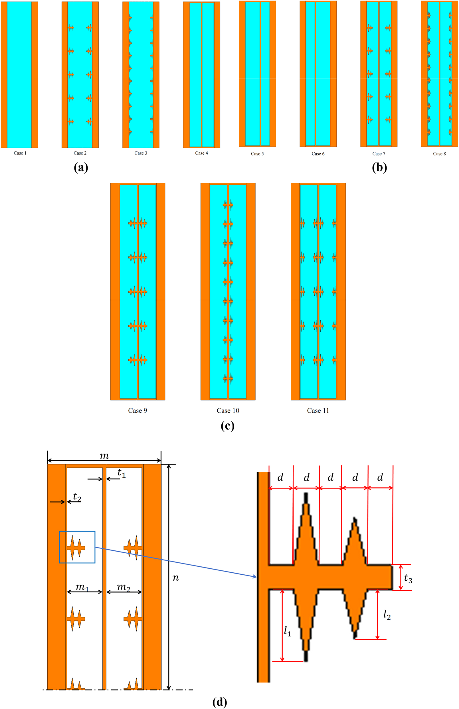
Schematic representing the scenarios examined in the current study. (a): Case1-4. (b): Case 5–8. (c): Case 9–11. (d): Dimension details of plate and branch-structured fin for the current study (Case 7).
Table 2 depict the thermophysical properties of used nanoparticles and PCM. Table 1 provides additional information on the dimensions of the assessed states.
Computational domain’s geometrical dimensions.
| m/mm | n/mm | m 2/mm | m 1/mm | t 1/mm | t 2/mm | t 3/mm | l 1/mm | l 2/mm | d/mm | |
|---|---|---|---|---|---|---|---|---|---|---|
| Case 1 | 64 | 127 | _ | _ | _ | 1 | _ | _ | _ | _ |
| Case 2 | 64 | 127 | _ | _ | _ | 1 | 2 | 6 | 4 | 2 |
| Case 3 | 64 | 127 | _ | _ | _ | 1 | 2 | 6 | 4 | 1 |
| Case 4 | 64 | 127 | 20 | 20 | 2 | 1 | _ | _ | _ | _ |
| Case 5 | 64 | 127 | 15 | 25 | 2 | 1 | _ | _ | _ | _ |
| Case 6 | 64 | 127 | 25 | 15 | 2 | 1 | _ | _ | _ | _ |
| Case7 | 64 | 127 | 20 | 20 | 2 | 1 | 2 | 6 | 4 | 2 |
| Case 8 | 64 | 127 | 20 | 20 | 2 | 1 | 2 | 6 | 4 | 1 |
| Case 9 | 64 | 127 | 20 | 20 | 2 | 1 | 2 | 6 | 4 | 2 |
| Case 10 | 64 | 127 | 20 | 20 | 2 | 1 | 2 | 6 | 4 | 1 |
| Case 11 | 64 | 127 | 20 | 20 | 2 | 1 | 2 | 6 | 4 | 1 |
PCM and nanoparticles thermophysical properties.
| Physical properties | Molten salt (pure PCM) | Al 2 O 3 | MWCNT |
|---|---|---|---|
| Density | 1,980 | 3970.0 | 1,600 |
| Specific heat | 1,575 | 0765.0 | 796 |
| Viscosity | 0.00461 | ||
| Thermal conductivity | 0.59 | 0040.0 | 3000 |
| Solidus temperature Liquidus temperature |
495.9 519 |
2.2 Assumptions and governing equations
The PCM box has been estimated to be fully loaded with PCM. Since there isn’t an air void during the phase shift procedure, the PCM volume should be fixed [47], 48]. The governing equations are formulated using the following conditions [49], 50].
It is assumed that the fluid flow is axisymmetric, laminar, transient, Newtonian and incompressible.
Owing to lower velocities, viscous dissipations are neglected.
Boussinesq approximation is used to determine density and buoyant force.
No heat is lost to the environment because the heat storage units’ exterior is well-insulated.
The walls non-slip properties are considered.
Gravity acceleration is measured along the negative y-axis (downward).
The aforementioned assumptions can be used to formulate the following equations [53]
Here, T stands for temperature, and H for the nano-PCMs total enthalpy, which considers both latent heat in the liquid phase and sensible heat in the solid phase. The density of the nano-PCM is represented by ρ
NEPCM, and k
eff defines the nano-PCM’s effective thermal conductivity. In this case, the operating temperature determines the specific heat (C
p
), latent heat, and liquid fraction. The damping element of Darcy law (
The value of the mushy zone (Bm) is 105 in current study based on the studies that have been published in the literature [49], 53], 54]. S L is added to the energy equation to account for the effects of latent heat and the phase transition process. Its value is defined as
In the abovementioned equation, the liquid fraction of the PCM is denoted by λ and is computed as follows
The λ value determines the PCM phase. When λ equals 0 the PCM is completely solid, and the liquid phase is represented by the liquid fraction value of 1.
The present study uses the Boussinesq approach to determine the density changes of PCM caused by temperature variations. This process involves computing the density as a temperature-dependent variable by applying Eq. (7). Whereas Eq. (8) can be used to calculate the h and total enthalpy (H).
Using the aforementioned formula, which is the ratio of the heat release value to the melting time, one may find the value of the heat release rate. It should be noticed that t
m
represents the melting time and
2.3 Initial and boundary conditions
The constraints on the boundaries of the LHTESS can be expressed as follows, initially, the PCM was assumed to be in a solid state, and the temperature was 303 K, in contrast, the HTF temperature was accompanied by the constant temperature of the tube wall, which was 520 K. It applies the adiabatic boundary condition to the outer walls. For every solid surface that comes into contact with the PCM, the non-slip boundary condition is applied. In conclusion, gravity is considered as a force acting on the body in a downward, vertical orientation.
2.4 Method of simulation
The charging phenomena are investigated in this work using the technique of the enthalpy porosity approach. Each computational cell in the current methodology is expected to have a similar porosity and liquid fraction. The phase change process of the PCM is simulated using ANSYS-FLUENT software, the pressure-velocity coupling is handled by SIMPLE methodology, and the gradients of the variables are calculated using the Green–Gauss cell-based approach. Additionally, the PRESTO scheme is applied to solve the pressure correction equations while the Finite volume technique is used to solve the momentum and energy equations. Under-relaxation parameter values for velocity components, pressure correction, liquid percent, and energy equation are taken to be 0.30, 0.30, 0.50 and 1.00. Additionally, the convergence criteria of 10−4, 10−4, & 10−6 are used to solve the continuity, momentum, and energy equations, respectively. Figure 2 disclosed the mesh development of current investigation. For the numerical simulation, a mesh size of elements 104,883 with nodes 107,968 is used. Once the mesh is built, the effects of the time step values on the numerical results are analyzed. Eventually, it is assumed that the value of the time step size is 0.2 s.
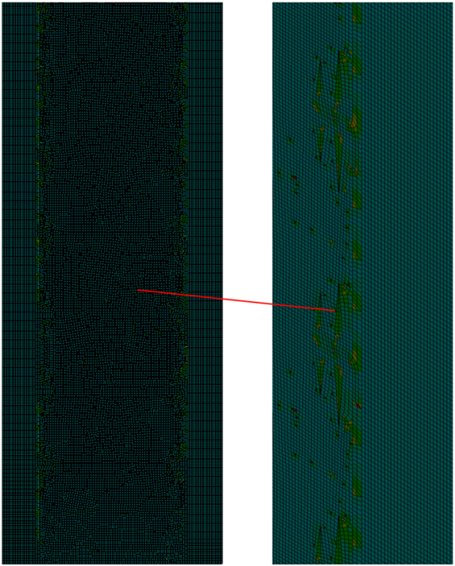
Graphical illustration of mesh for physical domain.
3 Result and discussion
One common technique for evaluating the melting process and studying the thermal behavior of PCM is numerical simulation [51], 55]. Numerous numerical simulations are performed for the TES system under examination, and the outcomes which include isotherms, the distribution of the solid-liquid border, and the transient liquid fraction are shown. In the present study, the PCM starts out completely solid and gradually melts into a liquid. In this investigation, the impacts on the charging performance of a vertical latent heat thermal storage system of adding a central plate, trapezoidal fins, and nanoparticles to the PCM enclosure are evaluated numerically. Finding the optimal situation with the quickest rate of heat release and the lowest melting time is the main objective of this investigation.
3.1 Liquid-fraction contours at t = 900s
Figure 3 illustrates the contours of the PCM liquid fraction without the addition of nanoparticles, with fins positioned at various locations and a center plate inserted at different positions throughout the PCM melting process after a 900 s. Figure 3(a) (Case-1) clearly demonstrates that after a duration of 900 s, the PCM solely melts in proximity to the interior of the outer walls due to boundary temperature. Numerical results indicate that just a 6.6 % quantity was melted at this moment. While Figure 3(a) (Case-2 and Case 3) depicts that PCM start to melt nearby the placed fins. 15.13 % of PCM were melted after 900 s in Case 2. In Figure 3(a) (Case-4), PCM melt more rapidly as compared to previous three cases due to the placement of central plate. 52.8 % of PCM melted during this time which is higher than previous results. Buoyancy causes the solid-liquid interface to warp and some liquid to start transforming along the area where the central plate separates it. This convective movement accelerates the melting rate close to the area nearby central plate. The temperature of the upper portion is higher than the lower part, as the image illustrates. This is due to the PCM’s preference for absorbing heat from the HTF inlet. A detailed investigation of the impact of central plate placement on the melting mode of the vertical latent heat thermal system is done in Figure 3(b) (Case-5 – Case 7). In Cases 5 to 8, the central plate is moved towards the PCM-based wall. Because some PCM is still solid in the middle, it is possible to see a decrease in the PCM melting rate in the outer enclosure when the central plate of the PCM-based thermal system is moved in the direction of the inner wall. Numerical outcomes agreed with this because the PCM was melted in this instance, which is less than the case of the tube when it was placed in the center. The outlines of the PCM liquid fraction during the PCM melting process, with trapezoidal-shaped fins and a central plate, are shown in Figure 3(c) (Cases 9 to 11). After 900 s an average of 71.4 %, 70 % and 68.4 % of PCM melted for Case 9, Case 10, and Case 11 respectively. When the phase change material (PCM) reaches a temperature of 519 K, it commences melting. As the PCM begins to melt, heat conduction becomes the predominant mode of heat transfer, resulting in a thin, flat layer of liquid PCM enveloping the center tube and fins. Figure 4 illustrates the contours for each scenario, demonstrating the liquid fraction of phase change material over time throughout the melting process with nanoparticles present.
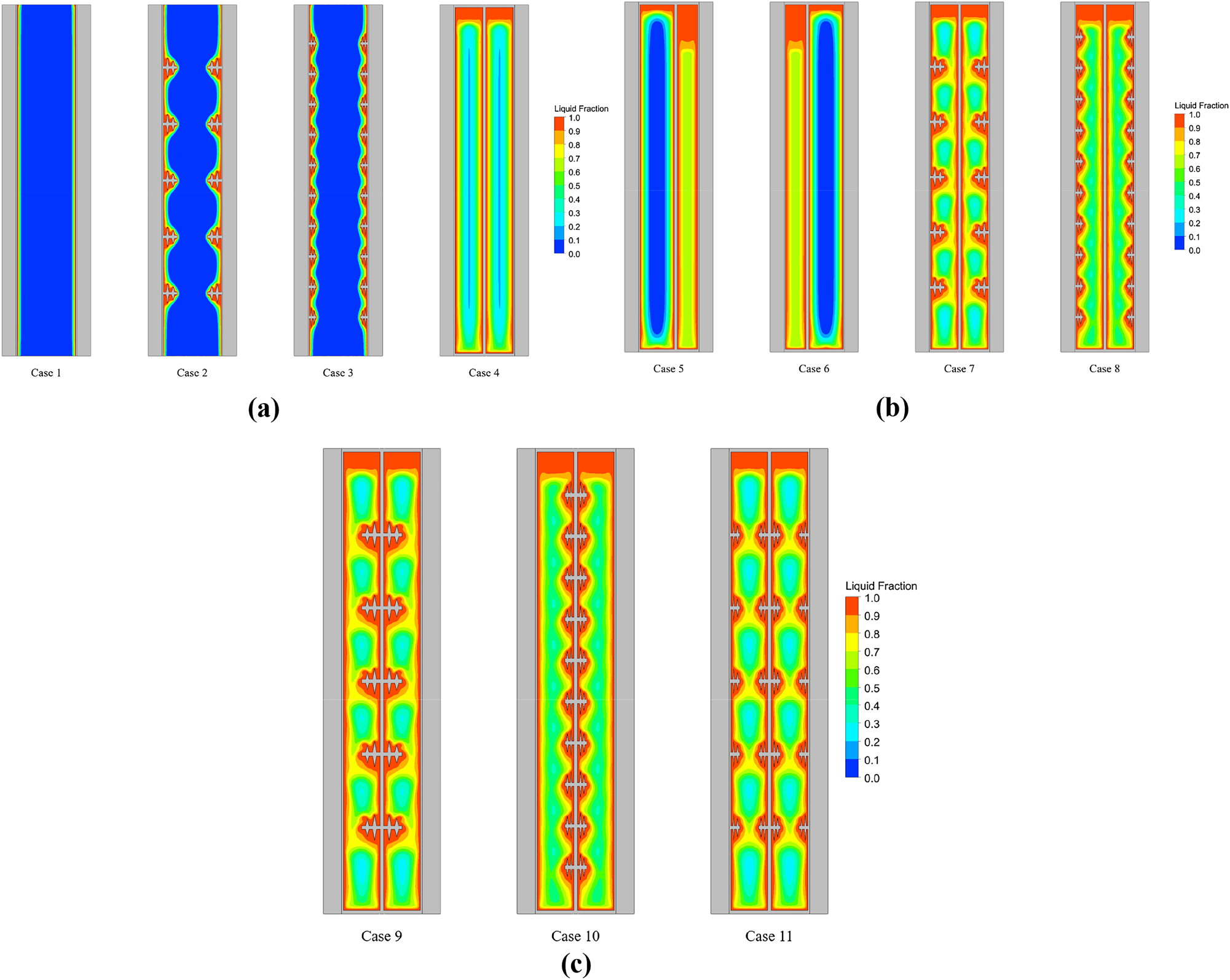
Evaluation of the liquid fraction contours after completing 900 s without incorporating nanoparticles. (a): Case 1–4. (b): Case 5–8. (c): Case 9–11.
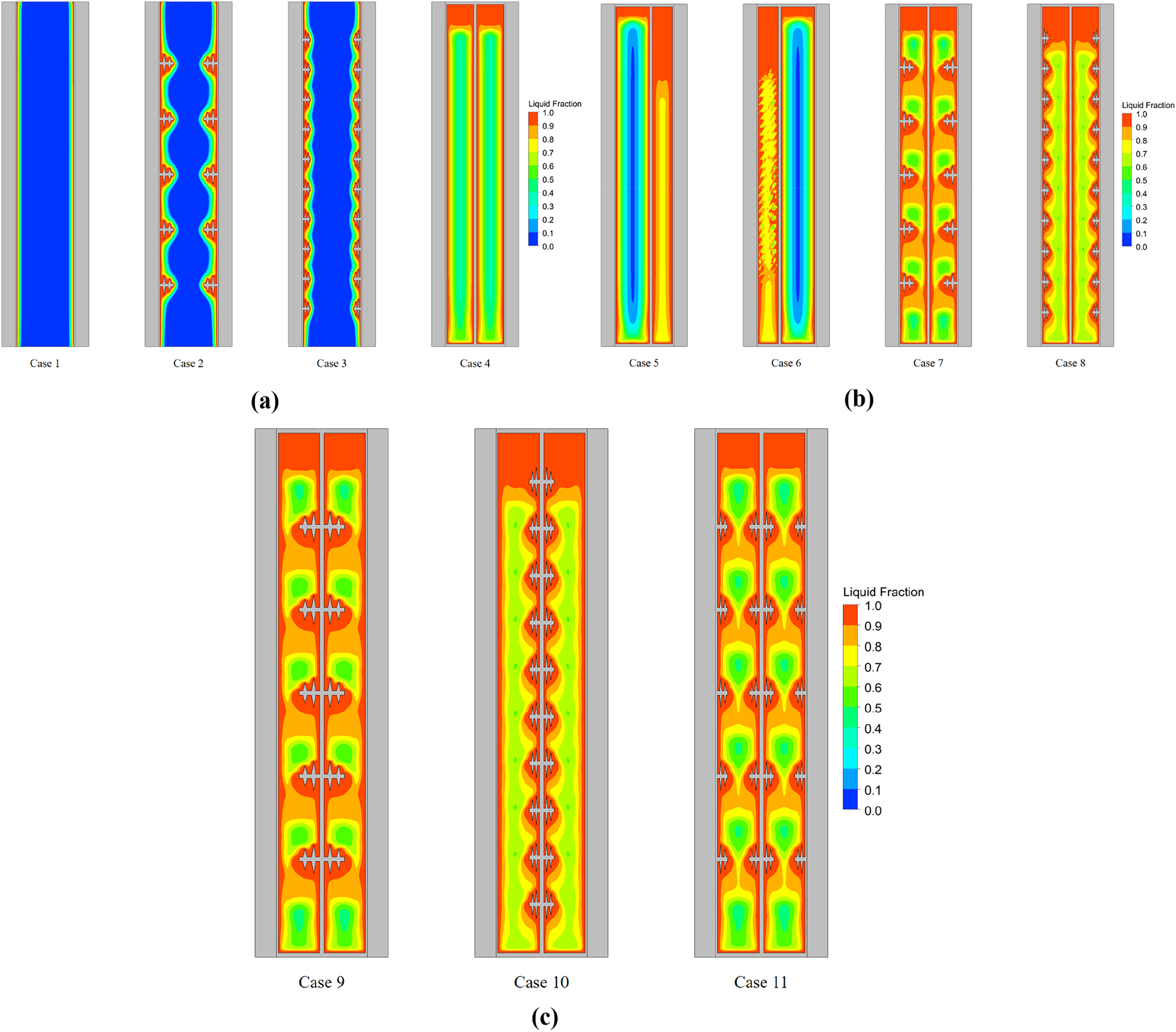
Evaluation of the liquid fraction contours after completing 900 s with nanoparticles. (a): Case 1–4. (b): Case 5–8. (c): Case 9–11.
Early in the melting process, the PCM phase change begins at the container walls and proceeds via heat conduction to the central plate walls and fins. It is evident from the produced graphical outcomes that incorporating nanoparticles with PCM significantly improves the melting rate of PCM, which is clearly visible in all cases, especially in Figure 4 (Case 1 to Case 11). Natural convection becomes the primary heat-transfer mechanism over time, causing circulation within the PCM. Adding nanoparticles enhances this mechanism, improving the melting phenomenon of the PCM. Because of this circulation, the cooler PCM falls because of its higher density, while the hotter PCM rises because of its lower density. Interestingly, the interior of the container’s outer wall and fins are exposed prominently to PCM, which means that this PCM region experiences more natural convection and conduction heat transfer than the other region. In case of nanoparticles, after 900 s, 9 %, 22 %, 65.7 %, 61 %, 82.8 %, 81.6 %, 82.8 %, 81.6 % and 80 % of nano-PCM melted for Case 1, Case 2, Case 4, Case 6, Case 7, Case 8, Case 9, Case 10, and Case 11, respectively.
3.2 Spatial distribution of average temperature at t = 900 s
Figure 5 illustrates the temperature contours for every case examined after a time interval of 900 s, to evaluate the impact of the implanted central wall variable location, fin configurations, and the incorporation of nanoparticles on the melting behavior of the PCM. Initially, a significant rise in temperature is observed at the inner part of the outer wall in Case-1 (Figure 5(a) and (d)), both with and without nanoparticles. However, it is clearly visible from Figure 5(a) and (d) that nanoparticle incorporation enhances the melting process. Moreover, the melting process at the bottom is slower than on the upper side. The reason for this phenomenon is the impact of gravity at the lower portion is much higher than on the upward section. Additionally, with their superior thermal conductivity, the PCM having nanoparticles (Figure 5(d) and (f)) shows a far more noticeable temperature rise over time than the case without nanoparticles (Figure 5(a) and (c)). The increased heat transmission made possible by the middle plate, the placement of fins, and the addition of nanoparticles is responsible for this elevated temperature rise. In Figure 5(f) maximum temperature is observed. In conclusion, nanoparticles enhance the efficiency of the melting process.
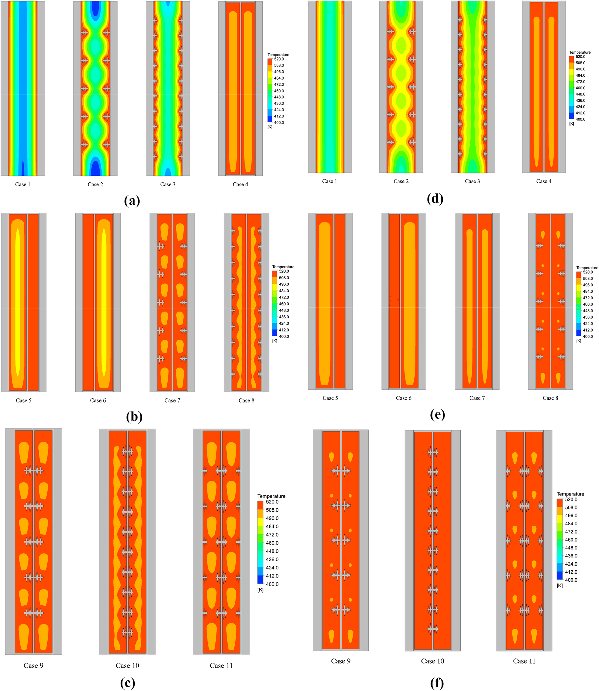
Comparing the temperature contours of different cases, with nanoparticle (right column) and without nanoparticles (left column). (a): Case 1–4 (without nanoparticles). (b): Case 5–8 (without nanoparticles). (c): Case 9–11 (without nanoparticles). (d): Case 1–4 (with nanoparticles). (e): Case 5–8 (with nanoparticles). (f): Case 9–11 (with nanoparticles).
3.3 Velocity-field comparison
Figure 6 illustrates the velocity distribution contours of molten salt (PCM) for various scenarios, with nanoparticles depicted on the right and without nanoparticles on the left. The addition of nanoparticles increases the viscosity and thermal conductivity of PCM. The entrapment of PCM molecules and the obstruction of their passage by the nanoparticle network is especially pronounced at elevated nanoparticle concentrations. The viscosity and thermal conductivity of a PCM can be altered by adding nanoparticles, placement of central tube and trapezoidal-type fins. Furthermore, fins and nanoparticles can slow down the PCM particle’s rate of settle-out and improve the stability of the PCM dispersion. The findings demonstrate that adding fins, a central plate, and nanoparticles can increase the PCM velocity concentration. This is because nanoparticles can act as a nucleation site for the formation of PCM crystals, which in turn promotes the creation of smaller, more uniform crystals. This accelerates the pace at which crystals grow and increases the PCM content. The velocity profile increases with increasing time scale for all cases (Case-1 to Case-11). The consequences of molten salt PCM material for different cases, on the velocity distributions, at various time conditions (300, 600, 900, & 1,200 s) are illustrated in Figure 7. The figure shows that there have been changes in velocity in the areas where melting has taken place. Four distinct time steps for 11 different cases have been found to have different velocity distributions. The PCM material’s velocity is determined to be higher for the higher time conditions than for the other scenarios. Consequently, the velocity distribution is highest for 1,200 s(case-10) and lowest for 300 s (Case-1).
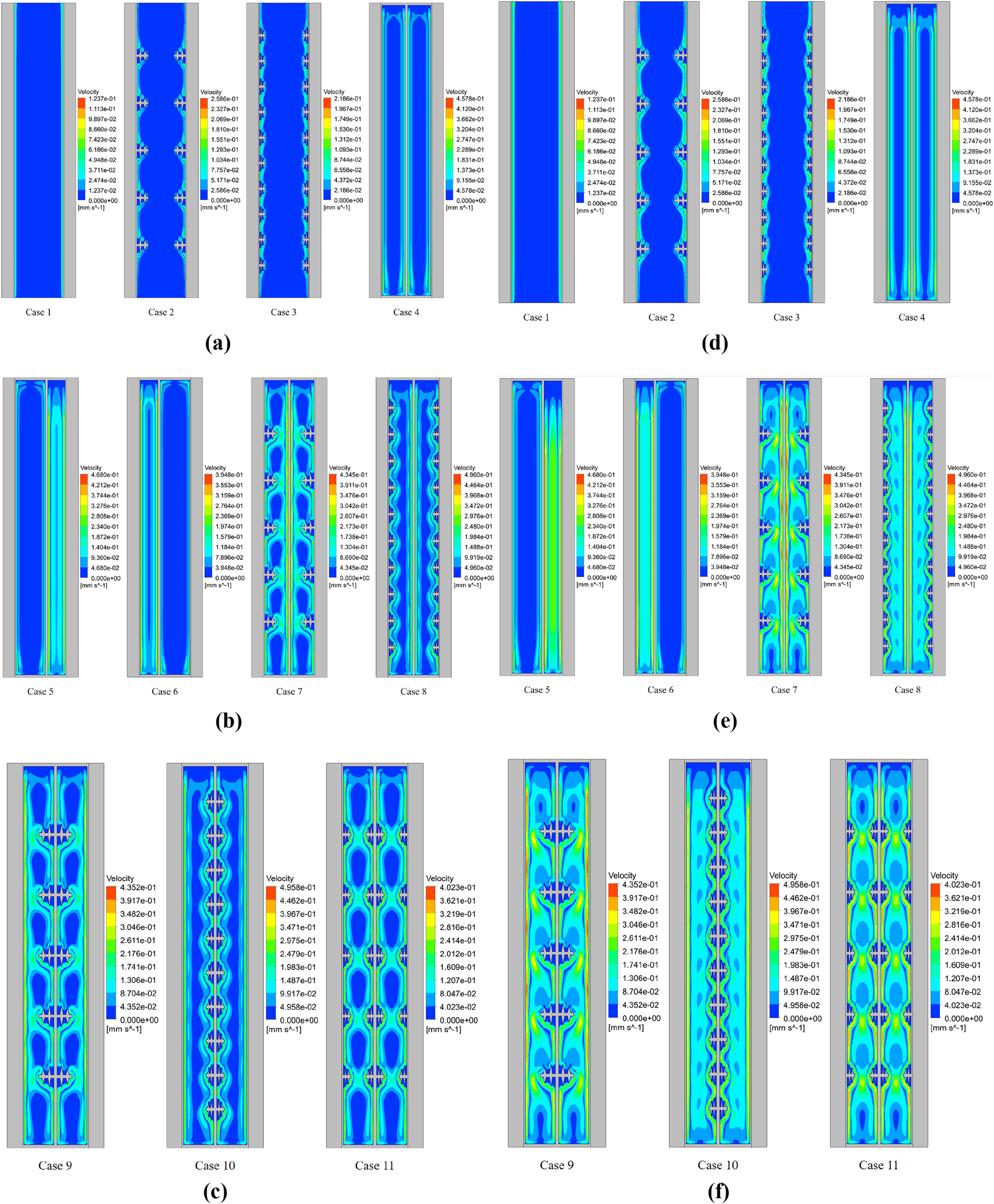
Velocity contours for different cases with and without nanoparticles. (a): Case 1–4 (without nanoparticles). (b): Case 5–8 (without nanoparticles). (c): Case 9–11 (without nanoparticles). (d): Case 1–4 (with nanoparticles). (e): Case 5–8 (with nanoparticles). (f): Case 9–11 (with nanoparticles).
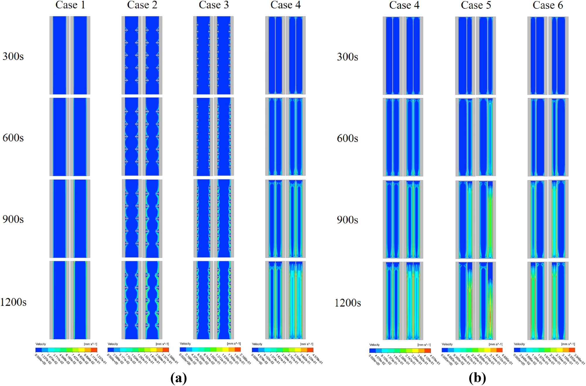
Velocity contours at different time instances. (a): Case 1–4. (b): Case 4–6.
3.4 Transient evolution of temperature and liquid-fraction contours for pure PCM and nano PCM
Figures 8 and 9, respectively, show the contours of the PCM liquid fraction over time with various scenarios (positioning of fins and central plate) during the PCM melting process in the absence and presence of nanoparticles. HTFs inlet direction is from top to bottom. A flat, thin layer of liquid PCM forms surrounding the fin and inner plate at the start of melting, with heat conduction accounting for the majority of PCM heat transfer (Figures 8 and 9 300 s).
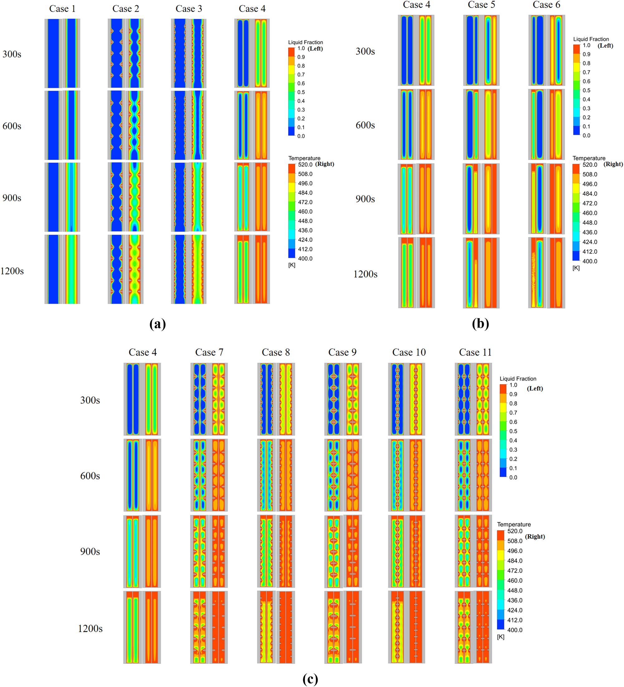
Evaluation of the temperature and liquid fraction contours at different time interval without incorporating nanoparticles. (a): Case 1–4 (without nanoparticles). (b): Case 4–6 (without nanoparticles). (c): Case 4, 7–11 (without nanoparticles).
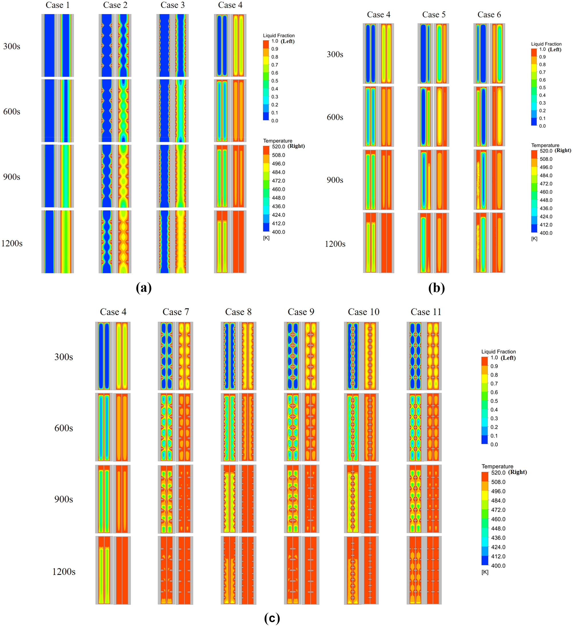
Evaluation of the temperature and liquid fraction contours at different time interval incorporating nanoparticles. (a): Case 1–4 (with nanoparticles). (b): Case 4–6 (with nanoparticles). (c): Case 4, 7–11 (with nanoparticles).
Furthermore, at low temperatures, the liquid layer’s thickness is lower, and at high temperatures, it becomes more significant. The PCM near the fins and central plate eventually melts completely (Figures 8 and 9 600 s), and substantial natural convection is caused by the PCM’s variable temperature specific densities. But this process is more rapid for the case having nanoparticles incorporated (Figure 9). Consequently, at this point in the melting of PCM, convective heat transport is dominant. By the final phase, natural convection had minimal impact because the majority of the PCM had melted (Figures 8 and 9 1,200 s). PCM melted at a slower pace without addition of nanoparticles throughout this operation and faster for the case in which nanoparticles are considered. It is important to note that the solid–liquid interface alterations in this work during PCM melting are similar to those in several published papers [56]. Furthermore, trapezoidal fins with varying positions (location) exhibit different solid–liquid interface, and a variable PCM melting rate, the different locations of the fins, the diverse the PCM melting rates. This suggests that the placement of trapezoidal fins with nanoparticles is important, and can alter the original PCM’s overall melting law.
3.5 Variation in liquid fraction and average temperature
The PCM’s liquid fraction and average temperature fluctuate over time, as seen in Figures 10 and 11, respectively. Notably, the liquid fraction exhibits comparable trends in every scenario. Initially, the PCM was in a solid state; with the passage of time, it starts to melt. However, from Figure 12(a), it is clear that in Case-4, incorporating nanoparticles, the liquid fraction of PCM increases rapidly compared to the other three cases, i.e., Case-1 to Case-3. This implies that in Case-4, PCM changes its form from solid to liquid more rapidly. Graphical illustrations depict that adding nanoparticles improve the liquid fraction significantly. From Figure 10(b) and (c), it is evident that placing fins and a central plate with the addition of nanoparticles, the liquid fraction time for PCM is reduced. This can be helpful in future studies and the design of PCM. The different configuration and placement of the central plate and fins could affect convective flows, flow patterns, and heat transfer efficiency, which could change how quickly PCM turns from solid to liquid.
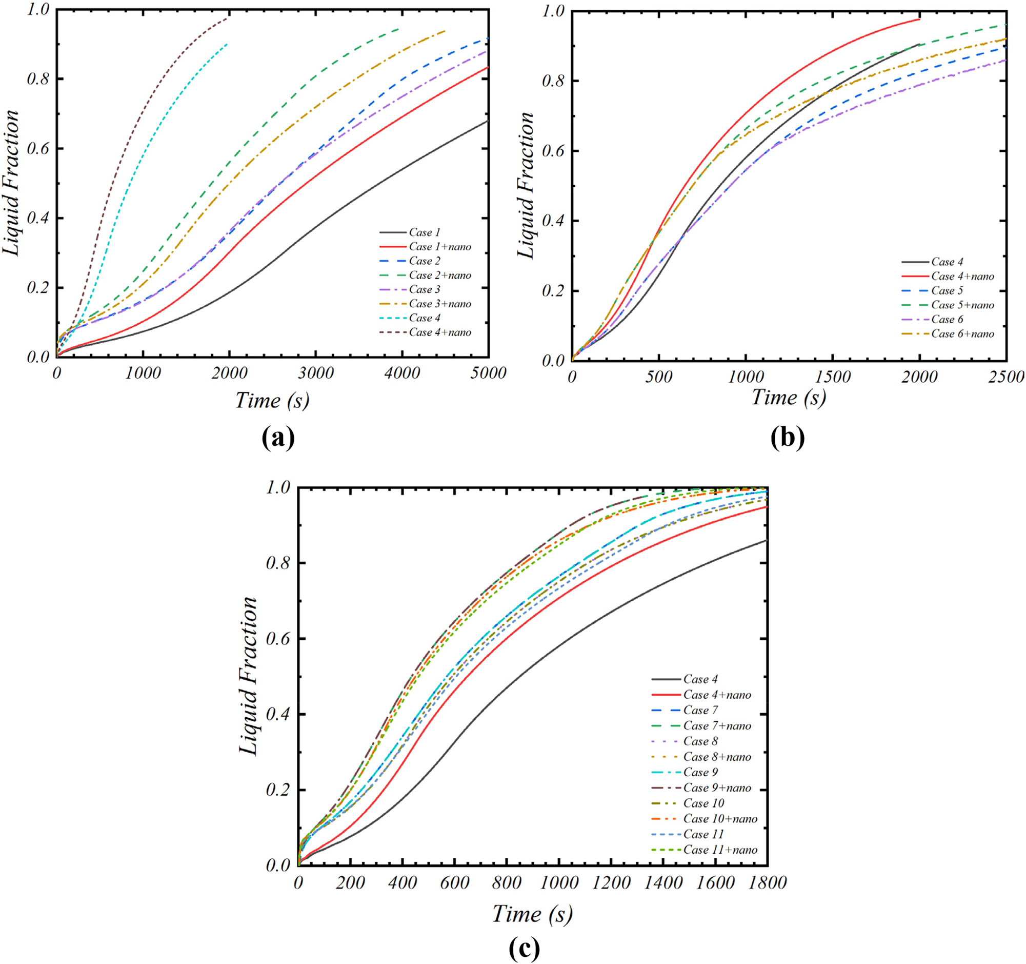
Variations in liquid fractions (a): Case 1–4, (b): Case 4–6, and (c): Case 4, 7–11 with respect to time.
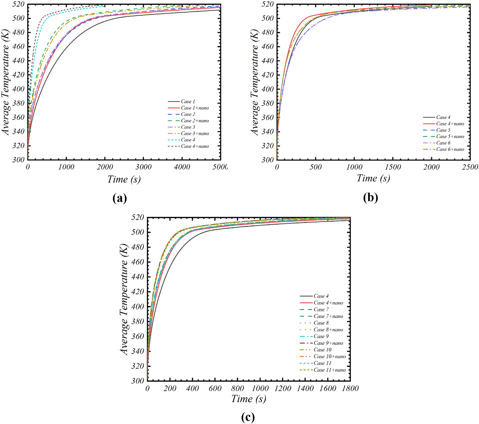
Variations in mean temperature of PCM with respect to time. (a): Case 1–4. (b): Case 4–6. (c): Case 4, 7–11.
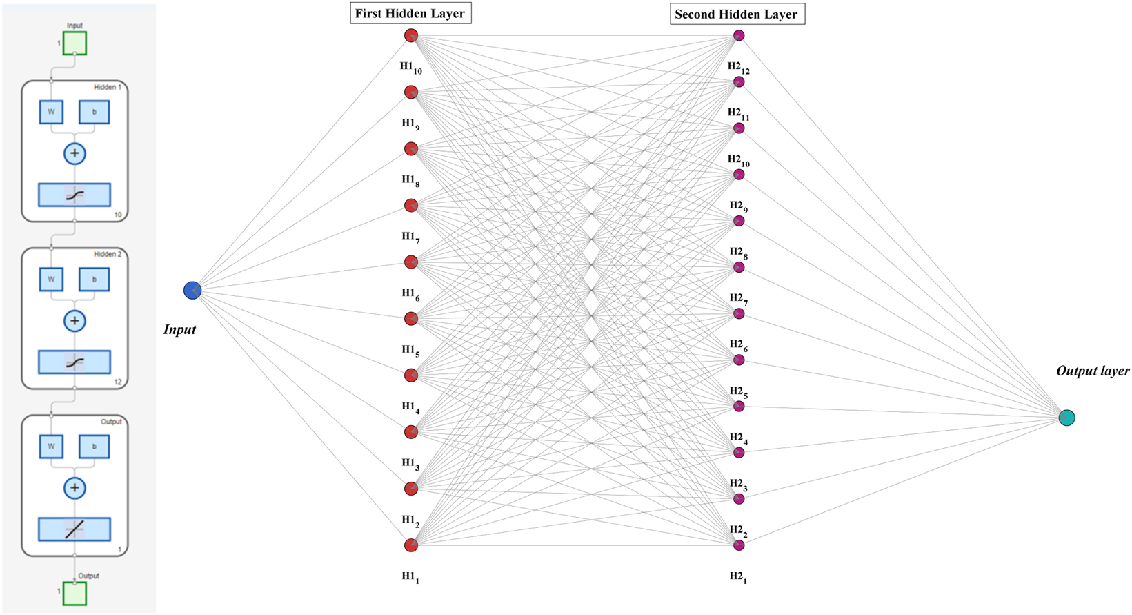
Artificial neural network architecture.
This study’s analysis of different scenarios led to the conclusion that the configuration known as Case-10 has superior melting process performance. In comparison to the other cases studied, this specific design shows the fastest melting rate and reaches the maximum temperature in the least amount of time. The mean temperature variations for the fins, nanoparticles, and central plate over time, at different amplitudes for different examples, are shown in Figure 11.
The findings show that all situations converge over time to a particular temperature value. From Figure 11(a) and (b), Case-4 with nanoparticles show most promising mean temperature as compared to other three cases present there. And from Figure 11(c), case 10 incorporating nanoparticles shows the best results among others. Conclusively, Cases 10 and 11 with nanoparticles show the quickest melting periods in accordance with the provided contours. Case 10, in contrast to the other cases, displays a greater mean temperature during the melting process.
4 ANN modelling and simulation
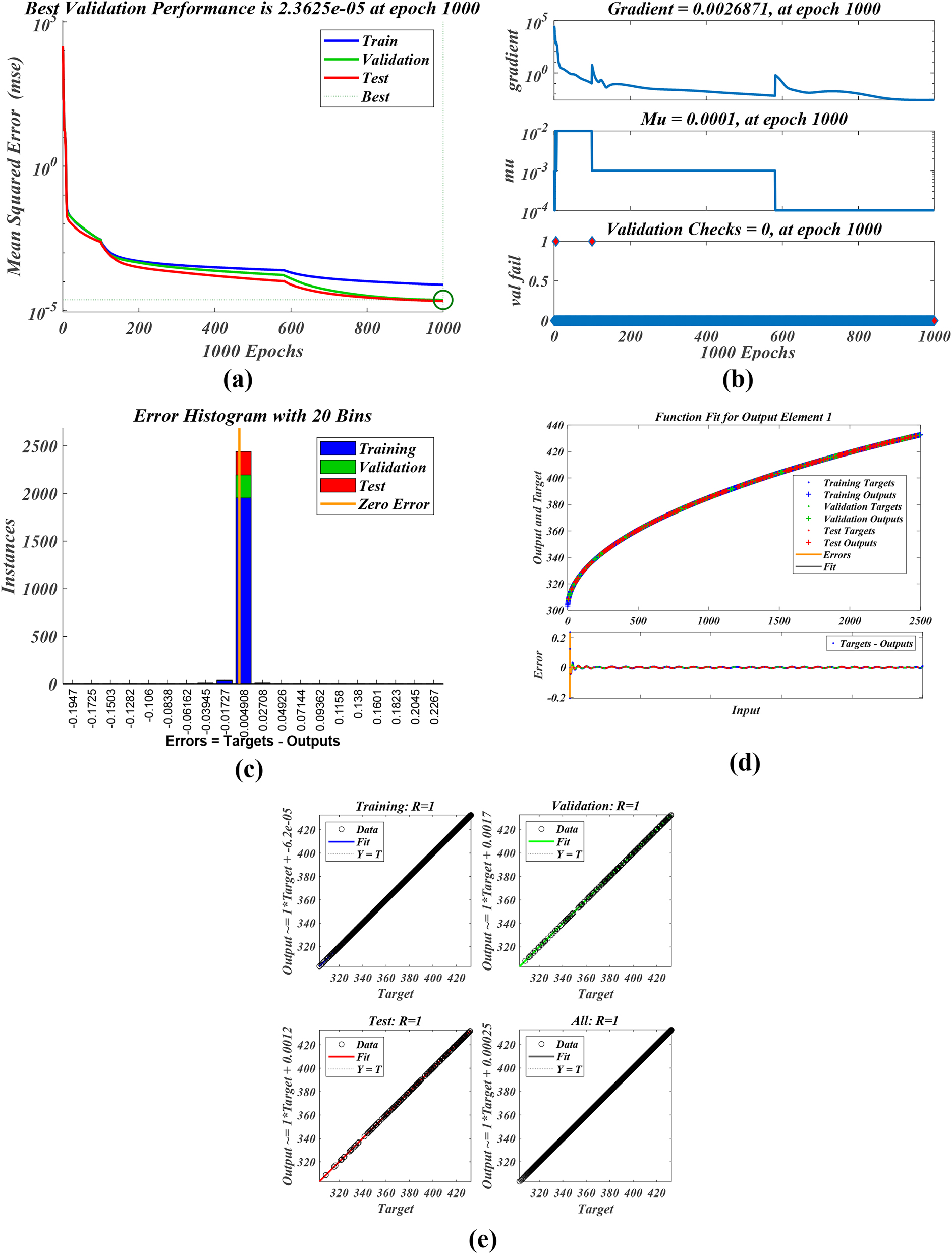
Artificial intelligence (AI) is a branch of computer science dedicated to developing solutions, making choices, and networking. It is used in various domains, including robotics, computer vision, and natural language processing. The artificial neural network (ANN), a widely employed method, emulates neural processes to operate similar to the human brain [57]. It proves crucial in addressing several complex physical engineering challenges. Consequently, it is applied in several mechanical systems, such as combustion engines, refrigeration units, and thermal apparatuses. Jose and Hotta [58] established an algorithm utilizing an ANN to comprehend the intricate thermal dynamics of NEPCM-based heat pipes and to enhance the prediction of their thermal characteristics. In this investigation, we applied the FF-ANN and the Levenberg–Marquardt algorithm (LMA). Of the complete dataset including 25,000 observations, 80 % (17,500) was allocated for training, 10 % (3,750) for validation, and testing the model’s estimations. The neural network (NN) architecture is depicted in Figure 12. NN include one input layer, two hidden layers and one output layer. The First hidden layer contains the 10 neurons, whereas, second hidden layer consists of 12 neurons. In Figure 13, weights, bias and activation function details for proposed NN training are presented. Figures 14–17 display the training parameters (MSE, gradient, Mu, error histogram, function fit, and regression) associated with NN training. NN training is carried out for four different parameters to illustrate its effectiveness.
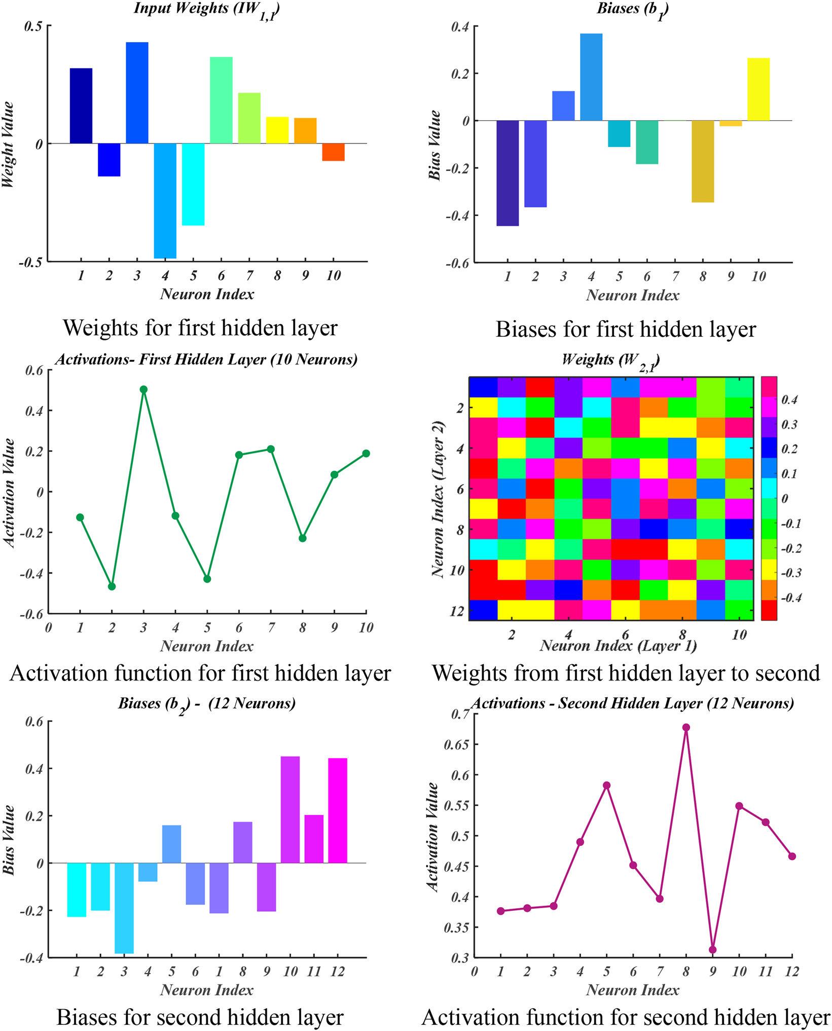
Neural network weights, biases and activation functions distribution details.
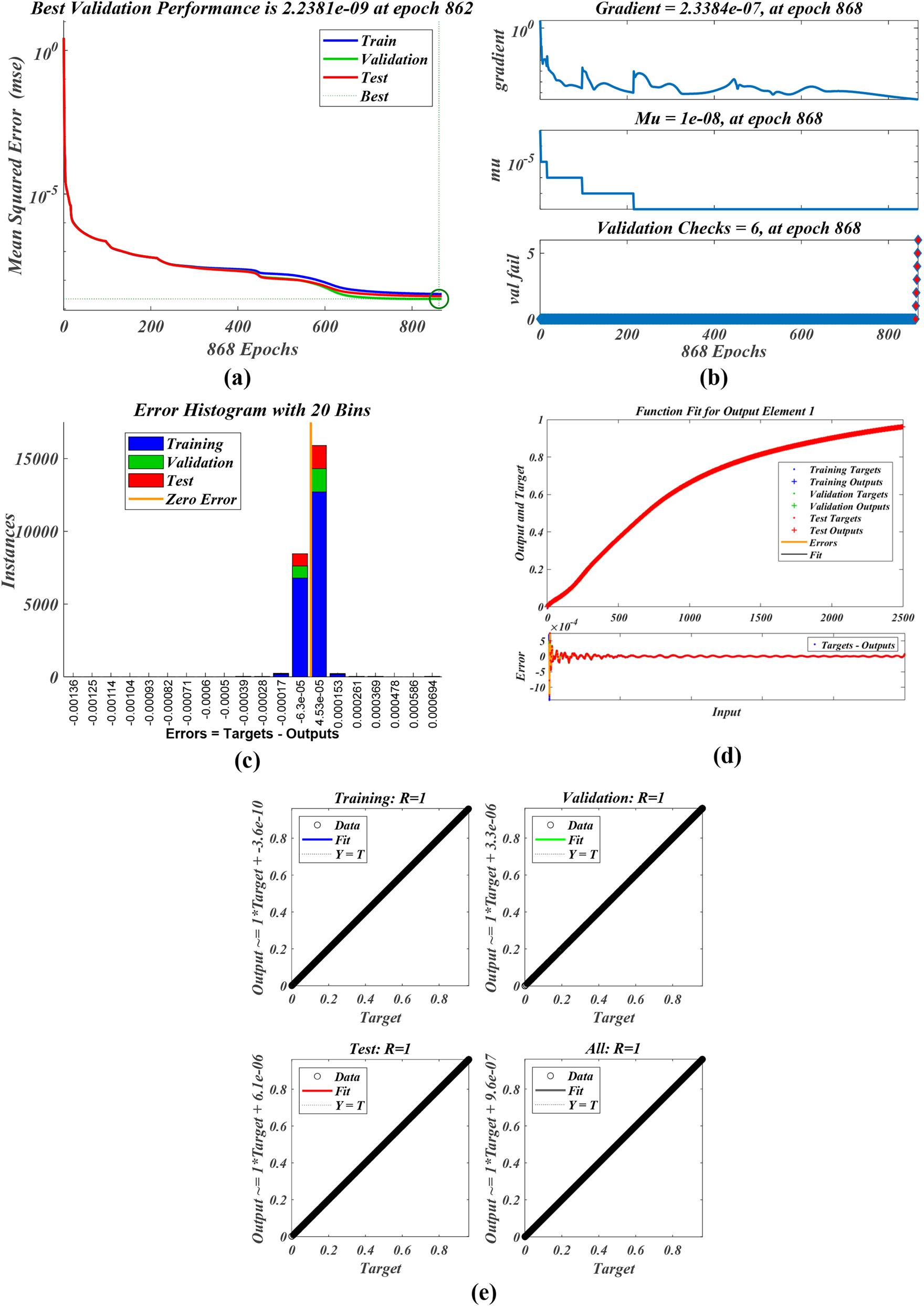
ANN training parameters for melting Case 5. (a): Training. (b): Training. (c): Error histogram. (d): Function fit. (e): Regression.
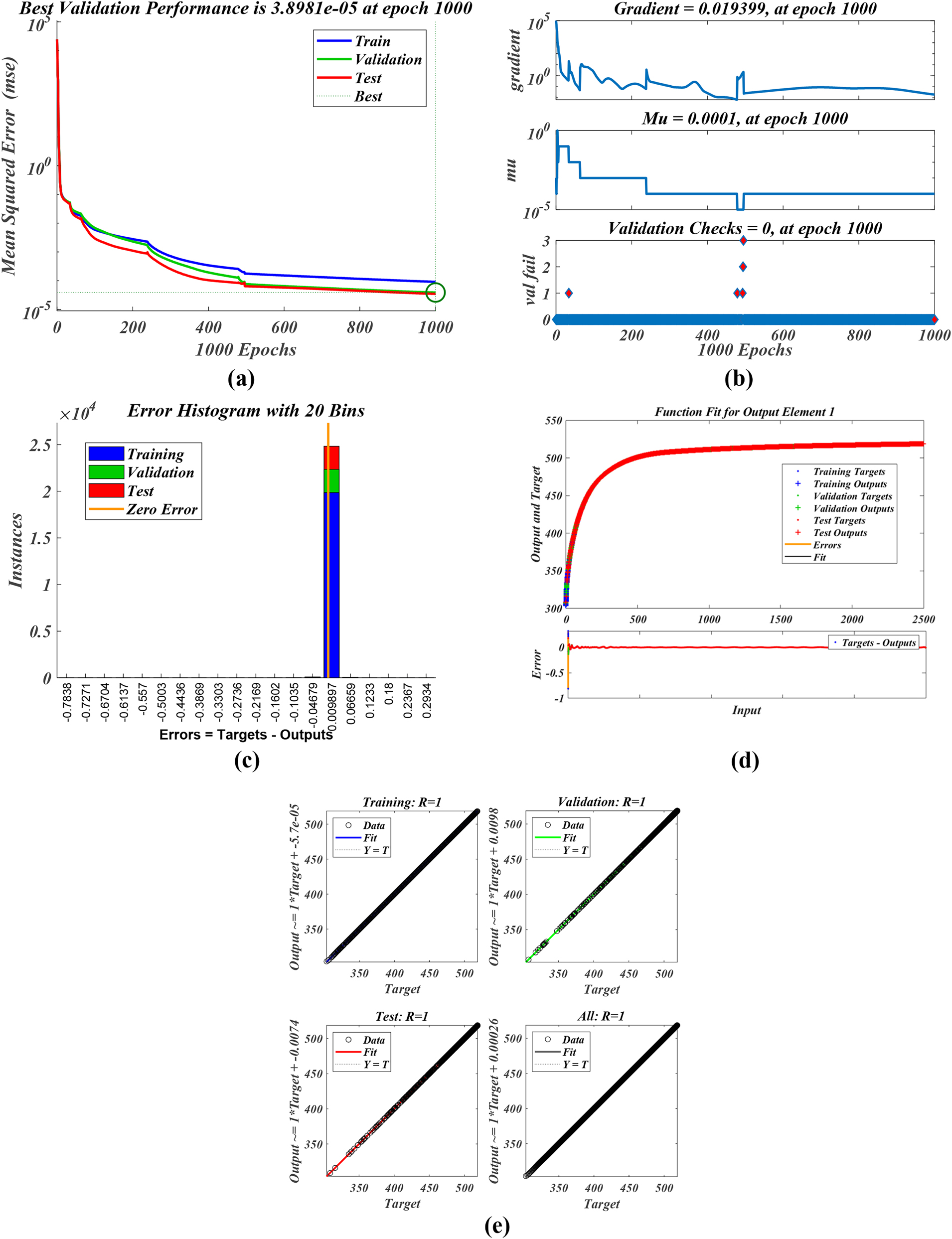
ANN training parameters for temperature Case 5. (a): MSE. (b): Training. (c): Error histogram. (d): Function fit. (e): Regression.
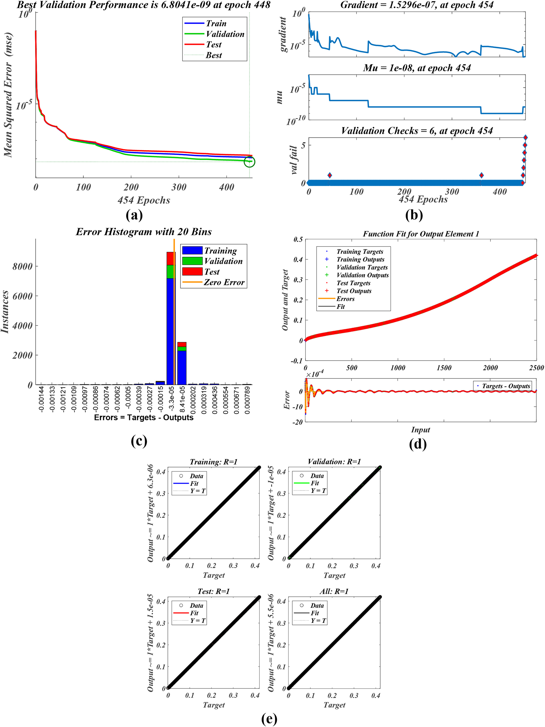
ANN training parameters for melting Case 1. (a): MSE. (b): Training. (c): Error histogram. (d): Function fit. (e): Regression.
ANN training parameters for temperature Case 1. (a): MSE. (b): Training. (c): Error histogram. (d): Function fit. (e): Regression.
Figures 14(a)–17(a) illustrate training advancement chart for ANN, displaying the mean squared error (MSE) throughout 862, 1,000, 454 and 1,000 epochs. The ANN model attained its optimal validation performance of MSE = 2.2381e-09, 3.8981e-05, 6.8041e-09 and 2.3625e-05 for 862, 1,000, 454 and 1,000 epochs. The training procedure effectively decreased the MSE for all datasets, achieving a stable state. The graph illustrates an algorithm that has been effectively trained, showcasing excellent results on both familiar (training) and unfamiliar (validation and test) datasets. This analysis indicates that the ANN model demonstrates robustness, exhibiting minimal risk of overfitting, and achieves outstanding performance as measured by the MSE metric. Three plots pertaining to the training method for developing a neural network are presented, specifically illustrating the gradient, the variable mu, and the validation checks over 5862, 1,000, 454 and 1,000 epochs, as depicted in Figures 14(b)–17(b). The gradient chart indicates that the algorithm is successfully converging, as evidenced by the gradient stabilizing at lower levels towards the conclusion of the training process. Consequently, the algorithm has reached a stable state that exhibits little overfitting, as evidenced by the validation examines conducted towards the conclusion of the training. The histogram indicates that the machine learning model demonstrates a high level of accuracy, with the majority of errors concentrated near zero. The findings are further substantiated by the analysis of error graphs presented in Figures 14(c)–17(c). The regression charts in Figures 14(e)–17(e) demonstrate the model’s outstanding performance throughout all datasets, with R-values approaching 1, signifying nearly perfect correlation. The function fit curves align closely with Output = Target, exhibiting minimal bias and confirming high accuracy along with robust generalization. Table 3 presents summary of statistical metrics to depict the evaluation of proposed ANN training.
Summary of statistical metrics for ANN training.
| Epoch | MSE | Gradient | Mu | Regression | |
|---|---|---|---|---|---|
| Melting case 5 | 868 | 2.2381e-09 | 2.3384e-07 | 1e-08 | 1.00 |
| Temperature case 5 | 1,000 | 3.8981e-05 | 0.019399 | 0.0001 | 1.00 |
| Melting case 1 | 454 | 2.2381e-09 | 2.3384e-07 | 1e-08 | 1.00 |
| Temperature case 1 | 1,000 | 2.3625e-05 | 0.002687 | 0.0001 | 1.00 |
The current numerical forecasts in Figure 18 align with the average temperature published by Mat et al. [56], thereby affirming the model credibility.
![Figure 18:
Validation of proposed CFD analysis with Mat et al. [56].](/document/doi/10.1515/ntrev-2025-0231/asset/graphic/j_ntrev-2025-0231_fig_018.jpg)
Validation of proposed CFD analysis with Mat et al. [56].
5 Conclusions
PCM can store and release huge amounts of energy during phase transitions like melting and solidification. One issue with most PCMs is their low thermal conductivity, which slows response time and heat transmission. To get around this problem, some techniques have been devised to increase PCMs heat conductivity, like adding fins, metal foams, or nanoparticles. In the current study, the effects on a LHTESS melting enhancement by adding a central plate, nanoparticles, and fins (trapezoidal shaped) at different locations to a PCM enclosure are studied numerically. Various design characteristics, such as fin length, fin number, fin thickness, central plate placement and location of placement, the addition of nanoparticles and PCM unit geometry, were analyzed as heat transfer enhancement approaches. There are particularly encouraging findings to ascertain how, the central plate, placement of fins at different location and addition of nanoparticles contributes to improving the PCM melting process. The obtained numerical results led to the following conclusions:
The melting process is significantly improved through the utilization of nanoparticles, an inner plate, and trapezoidal fins,
A regression score of 1 demonstrates an exceptional connection between CFD data and FF-ANN predictions,
In contrast to the conventional PCM, nano-PCM with central tube and trapezoidal shaped fins, the melting time will be shortened by 39 % for Case 1, and 41 % for Case 2,
By the placement of the trapezoidal-shaped fins, central plate, and nanoparticles, the melting time of the system reduces by 25 % for Case 2, 21. 1 % for Case 9 and 15.9 % for Case 11, while the proportion of fins and plate in the cross-section remains constant (with different placement),
Central plate and fins Increased average temperatures of PCM regions, enhanced heat exchange surface area, and increased insulation, resulting in reduced heat loss to the environment and augmented PCM storage of heat,
Projected outcomes indicate that the positioning of fins and the central plate is crucial, yielding varying results in the melting process based on their locations. For example, when the central tube was positioned in the middle 25 % (Case 4) of the average short melting time, and when the tube’s placement was altered from the center to the side walls, a 17 % (Case 6) reduction in average short melting time was observed,
An elevated HTF temperature accelerates the PCM melting rate.
Acknowledgments
This work was supported and funded by the Deanship of Scientific Research at Imam Mohammad Ibn Saud Islamic University (IMSIU) (grant number IMSIU-DDRSP2503).
-
Funding information: This work was supported and funded by the Deanship of Scientific Research at Imam Mohammad Ibn Saud Islamic University (IMSIU) (grant number IMSIU-DDRSP2503).
-
Author contribution: All authors have accepted responsibility for the entire content of this manuscript and approved its submission.
-
Conflict of interest: The authors state no conflict of interest.
-
Data availability statement: The datasets generated and/or analysed during the current study are available from the corresponding author on reasonable request.
References
1. Bashir, MA, Daabo, AM, Amber, KP, Khan, MS, Arshad, A, Elahi, H. Effect of phase change materials on the short-term thermal storage in the solar receiver of dish-micro gas turbine systems: a numerical analysis. Appl Therm Eng 2021;195:117179. https://doi.org/10.1016/j.applthermaleng.2021.117179.Suche in Google Scholar
2. Eisapour, M, Eisapour, AH, Hosseini, MJ, Talebizadehsardari, P. Exergy and energy analysis of wavy tubes photovoltaic-thermal systems using microencapsulated PCM nano-slurry coolant fluid. Appl Energy 2020;266:114849. https://doi.org/10.1016/j.apenergy.2020.114849.Suche in Google Scholar
3. Gao, Y, Zheng, Q, Jonsson, JC, Lubner, S, Curcija, C, Fernandes, L, et al.. Parametric study of solid-solid translucent phase change materials in building windows. Appl Energy 2021;301:117467. https://doi.org/10.1016/j.apenergy.2021.117467.Suche in Google Scholar
4. Jin, X, Zhang, S, Xu, X, Zhang, X. Effects of PCM state on its phase change performance and the thermal performance of building walls. Build Environ 2014;81:334–9. https://doi.org/10.1016/j.buildenv.2014.07.012.Suche in Google Scholar
5. Liu, L, Zhang, X, Liang, H, Niu, J, Wu, J-Y. Cooling storage performance of a novel phase change material nano-emulsion for room air-conditioning in a self-designed pilot thermal storage unit. Appl Energy 2022;308:118405. https://doi.org/10.1016/j.apenergy.2021.118405.Suche in Google Scholar
6. Wang, G, Yang, Y, Wang, S. Ocean thermal energy application technologies for unmanned underwater vehicles: a comprehensive review. Appl Energy 2020;278:115752. https://doi.org/10.1016/j.apenergy.2020.115752.Suche in Google Scholar
7. Arshad, A, Jabbal, M, Faraji, H, Talebizadehsardari, P, Bashir, MA, Yan, Y. Thermal performance of a phase change material-based heat sink in presence of nanoparticles and metal-foam to enhance cooling performance of electronics. J Energy Storage 2022;48:103882. https://doi.org/10.1016/j.est.2021.103882.Suche in Google Scholar
8. Nair, AM, Wilson, C, Huang, MJ, Griffiths, P, Hewitt, N. Phase change materials in building integrated space heating and domestic hot water applications: a review. J Energy Storage 2022;54:105227. https://doi.org/10.1016/j.est.2022.105227.Suche in Google Scholar
9. Schaetzle, WJ, Brett, CE, Grubbs, DM, Seppanen, MS. Thermal energy storage in aquifers:1980. Design and applications. New York: Pergamon.Suche in Google Scholar
10. Sharifi, N, Bergman, TL, Allen, MJ, Faghri, A. Melting and solidification enhancement using a combined heat pipe, foil approach. Int J Heat Mass Tran 2014;78:930–41. https://doi.org/10.1016/j.ijheatmasstransfer.2014.07.054.Suche in Google Scholar
11. Mahdi, JM, Nsofor, EC. Solidification enhancement of PCM in a triplex-tube thermal energy storage system with nanoparticles and fins. Appl Energy 2018;211:975–86. https://doi.org/10.1016/j.apenergy.2017.11.082.Suche in Google Scholar
12. Nada, SA, El-Nagar, DH, Hussein, HMS. Improving the thermal regulation and efficiency enhancement of PCM-integrated PV modules using nano particles. Energy Convers Manag 2018;166:735–43. https://doi.org/10.1016/j.enconman.2018.04.035.Suche in Google Scholar
13. Nada, SA, Alshaer, WG. Experimental investigation of thermal conductivity enhancement of carbon foam saturated with PCM and PCM/MWCNTs composite for energy storage systems. Heat Mass Tran 2019;55:2667–77. https://doi.org/10.1007/s00231-019-02610-4.Suche in Google Scholar
14. Kandelousi, MS. Effect of spatially variable magnetic field on ferrofluid flow and heat transfer considering constant heat flux boundary condition. The Eur Phys J Plus 2014;129:1–12. https://doi.org/10.1140/epjp/i2014-14248-2.Suche in Google Scholar
15. Rashid, FL, Rahbari, A, Ibrahem, RK, Talebizadehsardari, P, Basem, A, Kaood, A, et al.. Review of solidification and melting performance of phase change materials in the presence of magnetic field, rotation, tilt angle, and vibration. J Energy Storage 2023;67:107501. https://doi.org/10.1016/j.est.2023.107501.Suche in Google Scholar
16. Patil, RM, Ladekar, C. Experimental investigation for enhancement of latent heat storage using heat pipes in comparison with copper pipes. Int Refereed J Eng Sci 2014;3:44–52.Suche in Google Scholar
17. Senthilkumar, R, Sithivinanayagam, N, Shankar, N. Experimental investigation of solar water heater using phase change material. Int J Res Invent Technol 2014;2:1110–7.Suche in Google Scholar
18. Sarani, I, Payan, S, Nada, SA, Payan, A. Numerical investigation of an innovative discontinuous distribution of fins for solidification rate enhancement in PCM with and without nanoparticles. Appl Therm Eng 2020;176:115017. https://doi.org/10.1016/j.applthermaleng.2020.115017.Suche in Google Scholar
19. Alizadeh, M, Nabizadeh, A, Fazlollahtabar, A, Ganji, DD. An optimization study of solidification procedure in a wavy-wall storage unit considering the impacts of NEPCM and curved fin. Int Commun Heat Mass Tran 2021;124:105249. https://doi.org/10.1016/j.icheatmasstransfer.2021.105249.Suche in Google Scholar
20. Mozafari, M, Hooman, K, Lee, A, Cheng, S. Numerical study of a dual-PCM thermal energy storage unit with an optimized low-volume fin structure. Appl Therm Eng 2022;215:119026. https://doi.org/10.1016/j.applthermaleng.2022.119026.Suche in Google Scholar
21. Agyenim, F, Hewitt, N, Eames, P, Smyth, M. A review of materials, heat transfer and phase change problem formulation for latent heat thermal energy storage systems (LHTESS). Renew Sustain Energy Rev 2010;14:615–28. https://doi.org/10.1016/j.rser.2009.10.015.Suche in Google Scholar
22. Farid, M, Khudhair, AM, Razack, SAK, Al-Hallaj, S. A review on phase change energy storage: materials and applications. Thermal Energy Storage with Phase Change Mater 2021:4–23.10.1201/9780367567699-2Suche in Google Scholar
23. Sharma, A, Tyagi, VV, Chen, CR, Buddhi, D. Review on thermal energy storage with phase change materials and applications. Renew Sustain Energy Rev 2009;13:318–45. https://doi.org/10.1016/j.rser.2007.10.005.Suche in Google Scholar
24. Kalnæs, SE, Jelle, BP. Phase change materials and products for building applications: a state-of-the-art review and future research opportunities. Energy Build 2015;94:150–76. https://doi.org/10.1016/j.enbuild.2015.02.023.Suche in Google Scholar
25. Ren, Q, Guo, P, Zhu, J. Thermal management of electronic devices using pin-fin based cascade microencapsulated PCM/expanded graphite composite. Int J Heat Mass Tran 2020;149:119199. https://doi.org/10.1016/j.ijheatmasstransfer.2019.119199.Suche in Google Scholar
26. Pielichowska, K, Pielichowski, K. Phase change materials for thermal energy storage. Prog Mater Sci 2014;65:67–123. https://doi.org/10.1016/j.pmatsci.2014.03.005.Suche in Google Scholar
27. Douvi, E, Pagkalos, C, Dogkas, G, Koukou, MK, Stathopoulos, VN, Caouris, Y, et al.. Phase change materials in solar domestic hot water systems: a review. Int J Thermofluids 2021;10:100075. https://doi.org/10.1016/j.ijft.2021.100075.Suche in Google Scholar
28. Souayfane, F, Fardoun, F, Biwole, P-H. 2016 Phase change materials (PCM) for cooling applications in buildings: a review. Energy Build;129:396–431.10.1016/j.enbuild.2016.04.006Suche in Google Scholar
29. Wang, Y, Yu, K, Ling, X. Experimental and modeling study on thermal performance of hydrated salt latent heat thermal energy storage system. Energy Convers Manag 2019;198:111796. https://doi.org/10.1016/j.enconman.2019.111796.Suche in Google Scholar
30. Shahsavar, A, Shaham, A, Talebizadehsardari, P. Wavy channels triple-tube LHS unit with sinusoidal variable wavelength in charging/discharging mechanism. Int Commun Heat Mass Tran 2019;107:93–105. https://doi.org/10.1016/j.icheatmasstransfer.2019.05.012.Suche in Google Scholar
31. Chen, CQ, Diao, YH, Zhao, YH, Ji, WH, Wang, ZY, Liang, L. Thermal performance of a thermal-storage unit by using a multichannel flat tube and rectangular fins. Appl Energy 2019;250:1280–91. https://doi.org/10.1016/j.apenergy.2019.05.095.Suche in Google Scholar
32. Mostafavi, A, Parhizi, M, Jain, A. Semi-analytical thermal modeling of transverse and longitudinal fins in a cylindrical phase change energy storage system. Int J Therm Sci 2020;153:106352. https://doi.org/10.1016/j.ijthermalsci.2020.106352.Suche in Google Scholar
33. Zhang, D-X, Yang, L-S, Kong, X-Q, Lu, X. Thermal control performance of a novel PCM-based pin fin hybrid heat sink. J Energy Storage 2025;131:117630. https://doi.org/10.1016/j.est.2025.117630.Suche in Google Scholar
34. Shahamat, P, Mehrdoost, Z. Numerical investigation of performance enhancement in a PCM-based thermal energy storage system using stair-shaped fins and nanoparticles. Appl Therm Eng 2024;257:124433. https://doi.org/10.1016/j.applthermaleng.2024.124433.Suche in Google Scholar
35. Babapoor, A, Karimi, G, Sabbaghi, S. Thermal characteristic of nanocomposite phase change materials during solidification process. J Energy Storage 2016;7:74–81. https://doi.org/10.1016/j.est.2016.05.006.Suche in Google Scholar
36. Sciacovelli, A, Colella, F, Verda, V. Melting of PCM in a thermal energy storage unit: numerical investigation and effect of nanoparticle enhancement. Int J Energy Res 2013;37:1610–23. https://doi.org/10.1002/er.2974.Suche in Google Scholar
37. Mosaffa, AH, Talati, F, Tabrizi, HB, Rosen, MA. Analytical modeling of PCM solidification in a shell and tube finned thermal storage for air conditioning systems. Energy Build 2012;49:356–61.10.1016/j.enbuild.2012.02.053Suche in Google Scholar
38. Mazhar, AR, Shukla, A, Liu, S. Numerical analysis of rectangular fins in a PCM for low-grade heat harnessing. Int J Therm Sci 2020;152:106306. https://doi.org/10.1016/j.ijthermalsci.2020.106306.Suche in Google Scholar
39. Jayaprakash, V, Ganesan, S, Beemkumar, N, Sunil Kumar, M, Kamakshi Priya, K, Kaliappan, N. Enhancing thermal energy storage efficiency: synthesis and analysis of hybrid Nano-PCMs. Results Eng 2025;26:104899. https://doi.org/10.1016/j.rineng.2025.104899.Suche in Google Scholar
40. NematpourKeshteli, A, Iasiello, M, Langella, G, Bianco, N. Optimization of the thermal performance of a lobed triplex-tube solar thermal storage system equipped with a phase change material. Heliyon 2024;10:e36105. https://doi.org/10.1016/j.heliyon.2024.e36105.Suche in Google Scholar
41. Rashid, FL, Dhaidan, NS, Mahdi, AJ, Kadhim, SA, Hammoodi, KA, Al-Obaidi, MA, et al.. Heat transfer enhancement of phase change materials using tree shaped fins: a comprehensive review. Int Commun Heat Mass Tran 2025;162:108573. https://doi.org/10.1016/j.icheatmasstransfer.2024.108573.Suche in Google Scholar
42. Yao, S, Huang, X. Study on solidification performance of PCM by longitudinal triangular fins in a triplex-tube thermal energy storage system. Energy 2021;227:120527. https://doi.org/10.1016/j.energy.2021.120527.Suche in Google Scholar
43. Rashid, FL, Dhaidan, NS, Mahdi, AJ, Azziz, HN, Parveen, R, Togun, H, et al.. Heat transfer enhancement of phase change materials using letters-shaped fins: a review. Int Commun Heat Mass Tran 2024;159:108096. https://doi.org/10.1016/j.icheatmasstransfer.2024.108096.Suche in Google Scholar
44. Younis, O, Mourad, A, Aissa, A, Qasem, NAA, Abed, AM, Akbari, OA, et al.. Numerical investigation of thermal energy storage system loaded with nano-enhanced phase change material with Koch snowflake fractal cross-section. J Energy Storage 2022;56:106016. https://doi.org/10.1016/j.est.2022.106016.Suche in Google Scholar
45. Mourad, A, Aissa, A, Abed, AM, Smaisim, GF, Toghraie, D, Fazilati, MA, et al.. The numerical analysis of the melting process in a modified shell-and-tube phase change material heat storage system. J Energy Storage 2022;55:105827. https://doi.org/10.1016/j.est.2022.105827.Suche in Google Scholar
46. Morciano, M, Fasano, M, Chiavazzo, E, Mongibello, L. Trending applications of Phase change materials in sustainable thermal engineering: an up-to-date review. Energy Convers Manag X 2025;25:100862. https://doi.org/10.1016/j.ecmx.2024.100862.Suche in Google Scholar
47. Chiew, J, Chin, CS, Toh, WD, Gao, Z, Jia, J. Thermal state-of-expansion or melting of phase change material-based heat sink for underwater battery power system. J Energy Storage 2019;26:100956. https://doi.org/10.1016/j.est.2019.100956.Suche in Google Scholar
48. Hasan, A, Sarwar, J, Alnoman, H, Abdelbaqi et, S. Yearly energy performance of a photovoltaic-phase change material (PV-PCM) system in hot climate. Sol Energy 2017;146:417–29. https://doi.org/10.1016/j.solener.2017.01.070.Suche in Google Scholar
49. Iranmanesh, A. Numerical study on discharging process of a latent heat triple-tube heat exchanger in the presence of a central plate using the enthalpy–porosity approach. J Therm Anal Calorim 2023;148:9673–99. https://doi.org/10.1007/s10973-023-12341-8.Suche in Google Scholar
50. Shahsavar, A, Khosravi, J, Mohammed, HI, Talebizadehsardari, P. Performance evaluation of melting/solidification mechanism in a variable wave-length wavy channel double-tube latent heat storage system. J Energy Storage 2020;27:101063. https://doi.org/10.1016/j.est.2019.101063.Suche in Google Scholar
51. El Idi, MM, Karkri, M. Heating and cooling conditions effects on the kinetic of phase change of PCM embedded in metal foam. Case Stud Therm Eng 2020;21:100716. https://doi.org/10.1016/j.csite.2020.100716.Suche in Google Scholar
52. Shahsavar, A, Majidzadeh, AH, Mahani, RB, Talebizadehsardari, P. Entropy and thermal performance analysis of PCM melting and solidification mechanisms in a wavy channel triplex-tube heat exchanger. Renew Energy 2021;165:52–72. https://doi.org/10.1016/j.renene.2020.11.074.Suche in Google Scholar
53. Wang, P, Wang, X, Huang, Y, Li, C, Peng, Z, Ding, Y. Thermal energy charging behaviour of a heat exchange device with a zigzag plate configuration containing multi-phase-change-materials (m-PCMs). Appl Energy 2015;142:328–36. https://doi.org/10.1016/j.apenergy.2014.12.050.Suche in Google Scholar
54. Ye, W-B, Zhu, D-S, Wang, N. Numerical simulation on phase-change thermal storage/release in a plate-fin unit. Appl Therm Eng 2011;31:3871–84. https://doi.org/10.1016/j.applthermaleng.2011.07.035.Suche in Google Scholar
55. Esapour, M, Hamzehnezhad, A, Darzi, AAR, Jourabian, M. Melting and solidification of PCM embedded in porous metal foam in horizontal multi-tube heat storage system. Energy Convers Manag 2018;171:398–410.10.1016/j.enconman.2018.05.086Suche in Google Scholar
56. Mat, S, Al-Abidi, AA, Sopian, K, Sulaiman, MY, Mohammad, AT. Enhance heat transfer for PCM melting in triplex tube with internal–external fins. Energy Convers Manag 2013;74:223–36. https://doi.org/10.1016/j.enconman.2013.05.003.Suche in Google Scholar
57. Patil, NG, Hotta, TK. A combined numerical simulation and optimization model for the cooling of IC chips under forced convection. Int J Mod Phys C 2020;31:2050081. https://doi.org/10.1142/s0129183120500813.Suche in Google Scholar
58. Jose, J, Hotta, TK. Thermal performance optimization of nano-enhanced phase change material-based heat pipe using combined artificial neural network and genetic algorithm approach. J Therm Sci Eng Appl 2025;17:021002. https://doi.org/10.1115/1.4067071.Suche in Google Scholar
© 2025 the author(s), published by De Gruyter, Berlin/Boston
This work is licensed under the Creative Commons Attribution 4.0 International License.
Artikel in diesem Heft
- Research Articles
- MHD radiative mixed convective flow of a sodium alginate-based hybrid nanofluid over a convectively heated extending sheet with Joule heating
- Experimental study of mortar incorporating nano-magnetite on engineering performance and radiation shielding
- Multicriteria-based optimization and multi-variable non-linear regression analysis of concrete containing blends of nano date palm ash and eggshell powder as cementitious materials
- A promising Ag2S/poly-2-amino-1-mercaptobenzene open-top spherical core–shell nanocomposite for optoelectronic devices: A one-pot technique
- Biogenic synthesized selenium nanoparticles combined chitosan nanoparticles controlled lung cancer growth via ROS generation and mitochondrial damage pathway
- Fabrication of PDMS nano-mold by deposition casting method
- Stimulus-responsive gradient hydrogel micro-actuators fabricated by two-photon polymerization-based 4D printing
- Physical aspects of radiative Carreau nanofluid flow with motile microorganisms movement under yield stress via oblique penetrable wedge
- Effect of polar functional groups on the hydrophobicity of carbon nanotubes-bacterial cellulose nanocomposite
- Review in green synthesis mechanisms, application, and future prospects for Garcinia mangostana L. (mangosteen)-derived nanoparticles
- Entropy generation and heat transfer in nonlinear Buoyancy–driven Darcy–Forchheimer hybrid nanofluids with activation energy
- Green synthesis of silver nanoparticles using Ginkgo biloba seed extract: Evaluation of antioxidant, anticancer, antifungal, and antibacterial activities
- A numerical analysis of heat and mass transfer in water-based hybrid nanofluid flow containing copper and alumina nanoparticles over an extending sheet
- Investigating the behaviour of electro-magneto-hydrodynamic Carreau nanofluid flow with slip effects over a stretching cylinder
- Electrospun thermoplastic polyurethane/nano-Ag-coated clear aligners for the inhibition of Streptococcus mutans and oral biofilm
- Investigation of the optoelectronic properties of a novel polypyrrole-multi-well carbon nanotubes/titanium oxide/aluminum oxide/p-silicon heterojunction
- Novel photothermal magnetic Janus membranes suitable for solar water desalination
- Green synthesis of silver nanoparticles using Ageratum conyzoides for activated carbon compositing to prepare antimicrobial cotton fabric
- Activation energy and Coriolis force impact on three-dimensional dusty nanofluid flow containing gyrotactic microorganisms: Machine learning and numerical approach
- Machine learning analysis of thermo-bioconvection in a micropolar hybrid nanofluid-filled square cavity with oxytactic microorganisms
- Research and improvement of mechanical properties of cement nanocomposites for well cementing
- Thermal and stability analysis of silver–water nanofluid flow over unsteady stretching sheet under the influence of heat generation/absorption at the boundary
- Cobalt iron oxide-infused silicone nanocomposites: Magnetoactive materials for remote actuation and sensing
- Magnesium-reinforced PMMA composite scaffolds: Synthesis, characterization, and 3D printing via stereolithography
- Bayesian inference-based physics-informed neural network for performance study of hybrid nanofluids
- Numerical simulation of non-Newtonian hybrid nanofluid flow subject to a heterogeneous/homogeneous chemical reaction over a Riga surface
- Enhancing the superhydrophobicity, UV-resistance, and antifungal properties of natural wood surfaces via in situ formation of ZnO, TiO2, and SiO2 particles
- Synthesis and electrochemical characterization of iron oxide/poly(2-methylaniline) nanohybrids for supercapacitor application
- Impacts of double stratification on thermally radiative third-grade nanofluid flow on elongating cylinder with homogeneous/heterogeneous reactions by implementing machine learning approach
- Synthesis of Cu4O3 nanoparticles using pumpkin seed extract: Optimization, antimicrobial, and cytotoxicity studies
- Cationic charge influence on the magnetic response of the Fe3O4–[Me2+ 1−y Me3+ y (OH2)] y+(Co3 2−) y/2·mH2O hydrotalcite system
- Pressure sensing intelligent martial arts short soldier combat protection system based on conjugated polymer nanocomposite materials
- Magnetohydrodynamics heat transfer rate under inclined buoyancy force for nano and dusty fluids: Response surface optimization for the thermal transport
- Fly ash and nano-graphene enhanced stabilization of engine oil-contaminated soils
- Enhancing natural fiber-reinforced biopolymer composites with graphene nanoplatelets: Mechanical, morphological, and thermal properties
- Performance evaluation of dual-scale strengthened co-bonded single-lap joints using carbon nanotubes and Z-pins with ANN
- Computational works of blood flow with dust particles and partially ionized containing tiny particles on a moving wedge: Applications of nanotechnology
- Hybridization of biocomposites with oil palm cellulose nanofibrils/graphene nanoplatelets reinforcement in green epoxy: A study of physical, thermal, mechanical, and morphological properties
- Design and preparation of micro-nano dual-scale particle-reinforced Cu–Al–V alloy: Research on the aluminothermic reduction process
- Spectral quasi-linearization and response optimization on magnetohydrodynamic flow via stenosed artery with hybrid and ternary solid nanoparticles: Support vector machine learning
- Ferrite/curcumin hybrid nanocomposite formulation: Physicochemical characterization, anticancer activity, and apoptotic and cell cycle analyses in skin cancer cells
- Enhanced therapeutic efficacy of Tamoxifen against breast cancer using extra virgin olive oil-based nanoemulsion delivery system
- A titanium oxide- and silver-based hybrid nanofluid flow between two Riga walls that converge and diverge through a machine-learning approach
- Enhancing convective heat transfer mechanisms through the rheological analysis of Casson nanofluid flow towards a stagnation point over an electro-magnetized surface
- Intrinsic self-sensing cementitious composites with hybrid nanofillers exhibiting excellent piezoresistivity
- Research on mechanical properties and sulfate erosion resistance of nano-reinforced coal gangue based geopolymer concrete
- Impact of surface and configurational features of chemically synthesized chains of Ni nanostars on the magnetization reversal process
- Porous sponge-like AsOI/poly(2-aminobenzene-1-thiol) nanocomposite photocathode for hydrogen production from artificial and natural seawater
- Multifaceted insights into WO3 nanoparticle-coupled antibiotics to modulate resistance in enteric pathogens of Houbara bustard birds
- Synthesis of sericin-coated silver nanoparticles and their applications for the anti-bacterial finishing of cotton fabric
- Enhancing chloride resistance of freeze–thaw affected concrete through innovative nanomaterial–polymer hybrid cementitious coating
- Development and performance evaluation of green aluminium metal matrix composites reinforced with graphene nanopowder and marble dust
- Morphological, physical, thermal, and mechanical properties of carbon nanotubes reinforced arrowroot starch composites
- Influence of the graphene oxide nanosheet on tensile behavior and failure characteristics of the cement composites after high-temperature treatment
- Central composite design modeling in optimizing heat transfer rate in the dissipative and reactive dynamics of viscoplastic nanomaterials deploying Joule and heat generation aspects
- Double diffusion of nano-enhanced phase change materials in connected porous channels: A hybrid ISPH-XGBoost approach
- Synergistic impacts of Thompson–Troian slip, Stefan blowing, and nonuniform heat generation on Casson nanofluid dynamics through a porous medium
- Optimization of abrasive water jet machining parameters for basalt fiber/SiO2 nanofiller reinforced composites
- Enhancing aesthetic durability of Zisha teapots via TiO2 nanoparticle surface modification: A study on self-cleaning, antimicrobial, and mechanical properties
- Nanocellulose solution based on iron(iii) sodium tartrate complexes
- Combating multidrug-resistant infections: Gold nanoparticles–chitosan–papain-integrated dual-action nanoplatform for enhanced antibacterial activity
- Novel royal jelly-mediated green synthesis of selenium nanoparticles and their multifunctional biological activities
- Direct bandgap transition for emission in GeSn nanowires
- Synthesis of ZnO nanoparticles with different morphologies using a microwave-based method and their antimicrobial activity
- Numerical investigation of convective heat and mass transfer in a trapezoidal cavity filled with ternary hybrid nanofluid and a central obstacle
- Halloysite nanotube enhanced polyurethane nanocomposites for advanced electroinsulating applications
- Low molar mass ionic liquid’s modified carbon nanotubes and its role in PVDF crystalline stress generation
- Green synthesis of polydopamine-functionalized silver nanoparticles conjugated with Ceftazidime: in silico and experimental approach for combating antibiotic-resistant bacteria and reducing toxicity
- Evaluating the influence of graphene nano powder inclusion on mechanical, vibrational and water absorption behaviour of ramie/abaca hybrid composites
- Dynamic-behavior of Casson-type hybrid nanofluids due to a stretching sheet under the coupled impacts of boundary slip and reaction-diffusion processes
- Influence of polyvinyl alcohol on the physicochemical and self-sensing properties of nano carbon black reinforced cement mortar
- Advanced machine learning approaches for predicting compressive and flexural strength of carbon nanotube–reinforced cement composites: a comparative study and model interpretability analysis
- Artificial neural network-driven insights into nanoparticle-enhanced phase change materials melting for heat storage optimization
- Review Articles
- A comprehensive review on hybrid plasmonic waveguides: Structures, applications, challenges, and future perspectives
- Nanoparticles in low-temperature preservation of biological systems of animal origin
- Fluorescent sulfur quantum dots for environmental monitoring
- Nanoscience systematic review methodology standardization
- Nanotechnology revolutionizing osteosarcoma treatment: Advances in targeted kinase inhibitors
- AFM: An important enabling technology for 2D materials and devices
- Carbon and 2D nanomaterial smart hydrogels for therapeutic applications
- Principles, applications and future prospects in photodegradation systems
- Do gold nanoparticles consistently benefit crop plants under both non-stressed and abiotic stress conditions?
- An updated overview of nanoparticle-induced cardiovascular toxicity
- Arginine as a promising amino acid for functionalized nanosystems: Innovations, challenges, and future directions
- Advancements in the use of cancer nanovaccines: Comprehensive insights with focus on lung and colon cancer
- Membrane-based biomimetic delivery systems for glioblastoma multiforme therapy
- The drug delivery systems based on nanoparticles for spinal cord injury repair
- Green synthesis, biomedical effects, and future trends of Ag/ZnO bimetallic nanoparticles: An update
- Application of magnesium and its compounds in biomaterials for nerve injury repair
- Micro/nanomotors in biomedicine: Construction and applications
- Hydrothermal synthesis of biomass-derived CQDs: Advances and applications
- Research progress in 3D bioprinting of skin: Challenges and opportunities
- Review on bio-selenium nanoparticles: Synthesis, protocols, and applications in biomedical processes
- Gold nanocrystals and nanorods functionalized with protein and polymeric ligands for environmental, energy storage, and diagnostic applications: A review
- An in-depth analysis of rotational and non-rotational piezoelectric energy harvesting beams: A comprehensive review
- Advancements in perovskite/CIGS tandem solar cells: Material synergies, device configurations, and economic viability for sustainable energy
- Deep learning in-depth analysis of crystal graph convolutional neural networks: A new era in materials discovery and its applications
- Review of recent nano TiO2 film coating methods, assessment techniques, and key problems for scaleup
- Antioxidant quantum dots for spinal cord injuries: A review on advancing neuroprotection and regeneration in neurological disorders
- Rise of polycatecholamine ultrathin films: From synthesis to smart applications
- Advancing microencapsulation strategies for bioactive compounds: Enhancing stability, bioavailability, and controlled release in food applications
- Advances in the design and manipulation of self-assembling peptide and protein nanostructures for biomedical applications
- Photocatalytic pervious concrete systems: from classic photocatalysis to luminescent photocatalysis
- Corrigendum
- Corrigendum to “Synthesis and characterization of smart stimuli-responsive herbal drug-encapsulated nanoniosome particles for efficient treatment of breast cancer”
- Special Issue on Advanced Nanomaterials for Carbon Capture, Environment and Utilization for Energy Sustainability - Part III
- Efficiency optimization of quantum dot photovoltaic cell by solar thermophotovoltaic system
- Exploring the diverse nanomaterials employed in dental prosthesis and implant techniques: An overview
- Electrochemical investigation of bismuth-doped anode materials for low‑temperature solid oxide fuel cells with boosted voltage using a DC-DC voltage converter
- Synthesis of HfSe2 and CuHfSe2 crystalline materials using the chemical vapor transport method and their applications in supercapacitor energy storage devices
- Special Issue on Green Nanotechnology and Nano-materials for Environment Sustainability
- Influence of nano-silica and nano-ferrite particles on mechanical and durability of sustainable concrete: A review
- Surfaces and interfaces analysis on different carboxymethylation reaction time of anionic cellulose nanoparticles derived from oil palm biomass
- Processing and effective utilization of lignocellulosic biomass: Nanocellulose, nanolignin, and nanoxylan for wastewater treatment
- Retraction
- Retraction of “Aging assessment of silicone rubber materials under corona discharge accompanied by humidity and UV radiation”